

Page 1
g
GE Consumer Home Services Training
TECHNICAL SERVICE GUIDE
Wizard
Super Capacity Dryer
TM
7.0 Cubic Foot
MODEL SERIES:
DPSE592EA0
DPSE592GA0
DNCD450EA0
DNCD450GA0
PUB # 31-9059 08/00
Page 2

!
IMPORTANT SAFETY NOTICE
The information in this service guide is intended for use by
individuals possessing adequate backgrounds of electrical,
electronic, and mechanical experience. Any attempt to repair a
major appliance may result in personal injury and property
damage. The manufacturer or seller cannot be responsible for the
interpretation of this information, nor can it assume any liability in
connection with its use.
WARNING
If the information in this manual is not followed exactly, a fire or
explosion may result causing proper ty damage, personal injury or
death. If you smell gas:
- Do not try to light any appliance.
- Do not touch any electrical switch; do not use any phone in
the building.
- Immediately call the gas supplier from a neighbor’s phone.
Follow the gas supplier’s instructions.
- If you cannot reach the gas supplier , call the fire department.
WARNING
To avoid personal injury, disconnect power before servicing this
product. If electrical power is required for diagnosis or test
purposes, disconnect the power immediately after performing the
necessary checks.
RECONNECT ALL GROUNDING DEVICES
If grounding wires, screws, straps, clips, nuts, or washers used
to complete a path to ground are removed for service, they must
be returned to their original position and properly fastened.
GE Consumer Home Services Training
Technical Service Guide
Copyright © 2000
All rights reserved. This ser vice guide may not be reproduced in whole or in part
in any form without written permission from the General Electric Company.
Page 3

Table of Contents
Dryer Nomenclature . . . . . . . . . . . . . . . . . . . . . . . . . . . . . . . . . . . . . . . . . . . . . . . 2
Warranty Information. . . . . . . . . . . . . . . . . . . . . . . . . . . . . . . . . . . . . . . . . . . . . . . 3
Installation Highlights. . . . . . . . . . . . . . . . . . . . . . . . . . . . . . . . . . . . . . . . . . . . . . 4
Operating Characteristics . . . . . . . . . . . . . . . . . . . . . . . . . . . . . . . . . . . . . . . . . . 8
Electronic Controls . . . . . . . . . . . . . . . . . . . . . . . . . . . . . . . . . . . . . . . . . . . . . . . 12
Control Settings . . . . . . . . . . . . . . . . . . . . . . . . . . . . . . . . . . . . . . . . . . . . . . . . . 15
Removal and Replacement . . . . . . . . . . . . . . . . . . . . . . . . . . . . . . . . . . . . . . . . 22
Schematics and Strip Circuits . . . . . . . . . . . . . . . . . . . . . . . . . . . . . . . . . . . . . . 24
Troubleshooting Flowcharts . . . . . . . . . . . . . . . . . . . . . . . . . . . . . . . . . . . . . . . 28
Illustrated Parts Breakdown . . . . . . . . . . . . . . . . . . . . . . . . . . . . . . . . . . . . . . . 30
- 1 -
Page 4
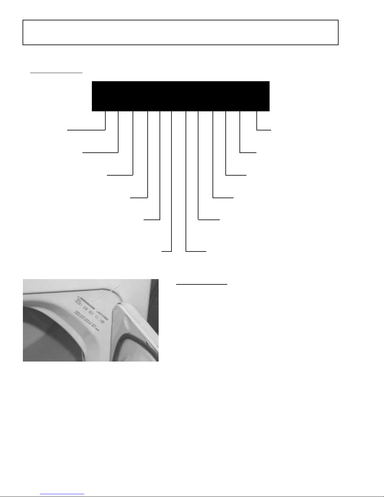
Model Number
Nomenclature
Dryer Nomenclature
D P S E 5 9 2 E A 0 W W
Product
D = Dryer
Features
P = Profile
Capacity
S = Super
Product T ype
E = Electronic
Number of Heat Select
5 = 5 Settings
Number of Cycles
9 = 9 Cycles
Nomenclature
Nomenclature
Key Attribute Color
W = White
Body Color
W = White
Engineering Revision
0 = None
Model Y ear
A = 2000
Fuel/Voltage
E = Electric
G = Gas
Dryer Control
2 = Electronic
Serial Number
The first two numbers of the serial number
identify the month and year of manufacture.
Example: AZ123456S = January, 2000
GEA00519
A - JAN 2005 - H
D - FEB 2004 - G
F - MAR 2003 - F
G - APR 2002 - D
H - MAY 2001 - A
L - JUN 2000 - Z
M - JUL 1999 - V
R - AUG 1998 - T
S - SEP 1997 - S
T - OCT 1996 - R
V - NOV 1995 - M
Z - DEC 1994 - L
Note: The technical sheet is located under the
control panel.
– 2 –
The letter designating the
year repeats every 12
years.
Example:
T - 1974
T - 1986
T - 1998
Page 5
Warranty Information
(For customers in the United States)
All warranty service is provided by our Factory
Service Centers or an authorized Customer Care
technician. For service, call 800-GE-CARES.
:fOdoirePehTroF :ecalpeRlliWEG
raeYenO
trapynA
ehtfoetadehtmorF
esahcruplanigiro
,egrahcfoeerf
.trap
sraeYeviF
ehtfoetadehtmorF
esahcruplanigiro
,ytnarrawdetimil
.stsocecivres
:revoCtoNlliWEGtahW
This warranty is valid only in the United States .
®
Warranty may vary in Canada. See your
approved Profile dealer for details.
sihtgniruD.pihsnamkrow
,ytnarrawraey-enolluf
murdreyrdyticapacrepusroegralartxeynA
sihtgniruD.pihsnamkrowroslairetamnitcefed
roslairetamnitcefedaoteudsliafhcihwreyrdehtfo
,edivorposlalliwEG
evitcefedehtecalperotecivresemoh-nidnaroballla
aoteudsliafhcihw
raey-ruoflanoitidda
emoh-nirorobalynarofelbisnopsereblliwuoy
• Service trips to your home to teach you
how to use the product.
• Improper installation.
• Failure of the product if it is abused, misused, or used for other than the intended
purpose or used commercially.
• Replacement of house fuses or resetting of
circuit breakers.
• Damage to the product caused by accident,
fire, floods or acts of God.
• Incidental or consequential damage to
personal property caused by possible
defects with this appliance.
Note: Some models may hav e an e xtended w arranty be y ond 5 y ears . Those models ha ve a special warranty sheet
enclosed when delivered to the customer . Unless that additional warranty sheet is attached, all other warranty
conditions shown abov e apply.
This warranty is extended to the original purchaser and any succeeding o wner for products purchased for home
use within the USA. In Alaska, the w arranty excludes the cost of shipping or service calls to your home.
Some states do not allow the exclusion or limitation of incidental or consequential damages. This w arranty giv es
you specific legal rights, and you ma y also ha v e other rights which vary from state to state. To kno w what y our legal
rights are, consult your local or state consumer affairs office or your state’s Attorney General.
Warrantor: General Electric Company, Louisville, KY 40225
– 3 –
Page 6
Installation Highlights
Exhaust Information
WARNING: Use only metal 4-in. duct. Do not use
duct longer than specified in the Exhaust Length
table.
Exhaust longer than specified will:
• Increase the drying times and the energy cost.
• Reduce the dryer’s life.
• Accumulate lint, creating a potential fire hazard.
The correct exhaust installation is your responsibility. Problems due to incorrect installation are not covered by the warranty.
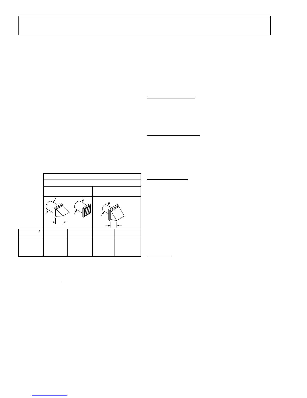
The maximum allowable length of the exhaust
system depends upon the type of duct, the number of
turns, the type of exhaust hood (wall cap), and all
conditions noted in this section. Both, rigid and
flexible metal ducts are shown in the following table.
EXHAUST LENGTH
RECOMMENDED MAXIMUM LENGTH
Exhaust Hood Types
Use only for short
run installations
4" DIA.
2-1/2"
Rigid
Metal
30 Feet
20 Feet
10 Feet
Flexible
Metal
15 Feet
10 Feet
GEA00565
No. of 90
Elbows
0
1
2
3
Recommended
4" DIA.
4"
Rigid
Metal
45 Feet
35 Feet
25 Feet
15 Feet
4" DIA.
Flexible
Metal
30 Feet
20 Feet
10 Feet
Exhaust System Checklist
Hood or Wall Cap
Note: To check airflow restrictions on the electric
dryer model, check amperage from the black wire
to pin #8. If 22.2 amps are shown and the relay
does not trip within 10 minutes, the airflow is OK.
If the relay trips the inlet thermostat withinin the
first 5 minutes and reads 11.1 amps, then airflow
is restricted.
Separation of Turns
For best perfor mance, separate all tur ns by at
least 4 ft of straight duct, including the distance
between the last turn and the dampened wall cap.
Turns Other Than 90°
• One turn of 45° or less may be ignored.
• Two 45° tur ns should be treated as one 90° turn.
• Each turn over 45° should be treated as one 90°
turn.
Sealing of Joints
• All joints should be tight to avoid leaks. The male
end of each section of duct must point away
from the dryer.
• Do not assemble the ductwork with fasteners
that extend into the duct: they will serve as a
collection point for lint.
• Duct joints can be made airtight and moisturetight by wrapping the overlapped joints with duct
tape.
Insulation
Duct work that runs through an unheated area or
is near air conditioning should be insulated to
reduce condensation and lint buildup.
• Terminate in a manner to prevent back drafts or
entry of birds or other wildlife.
• Termination should present minimal resistance
to the exhaust airflow and should require little or
no maintenance to prevent clogging.
• Never install a screen over the exhaust duct.
• Wall caps must be installed with opening
pointed down at least 12 in. above ground level
or any other obstruction.
• If roof vents or louvered plenums are used, they
must be equivalent to a 4-in. dampened wall
cap in regard to resistance to airflow, prevention
of back drafts, and maintenance required to
prevent clogging.
Exhaust Connection
WARNING: To reduce the risk of fire or personal
injury:
• This dryer must be exhausted to the outdoors.
• Use only metal duct.
• Do not terminate exhaust in a chimney, any gas
vent, under an enclosed floor (crawl space), or
into an attic: the accumulated lint could create a
fire hazard.
• Provide access for inspection and cleaning of
the exhaust system, especially at turns. Inspect
and clean at least once a year.
– 4 –
Page 7
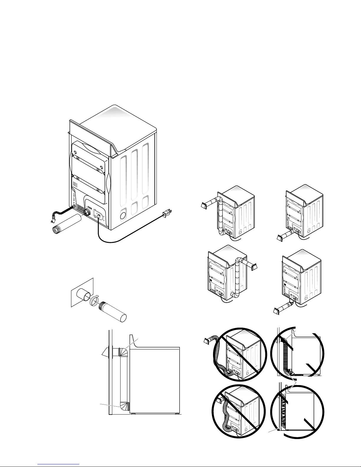
• Never terminate the exhaust into a common duct
GEA00556
Elbow Highly
Recommended
Do Not
Sit Dryer
On Flexible
Exhaust
Elbows Highly
Recommended
Do Not
Crush
Flexible
Exhaust
Against
Wall.
Elbow Highly
Recommended
GEA00557
with a kitchen exhaust: a combination of lint and
grease could create a fire hazard.
• Do not obstruct incoming or exhausted air.
This dryer comes ready for rear exhausting. If
space is limited, use the “Dryer Exhaust to Left or
Bottom of Cabinet” instructions to exhaust directly
from the left side or bottom of the cabinet.
STANDARD REAR EXHAUST
Using Flexible Metal Ducts
If rigid all-metal duct cannot be used, then flexible
all-metal venting can be used, but it will reduce the
maximum recommended duct length. In special
installations when it is impossible to make connection with the above recommendations, UL-listed
clothes dryer transition duct may be used as
transition venting between the dryer and wall
connection only. The use of this ducting will affect
dry time.
If flexible transition duct is necessary, you must
adhere to the following directions:
• Use the shortest duct length possible.
• Stretch the duct to its maximum length.
• Do not crush or collapse the duct.
• Never use transition duct inside the wall or
inside the dryer.
• Avoid resting the duct on sharp objects.
• Venting must conform to local building codes.
Cut The Standard Exhaust
Duct To Proper Length.
Avoid Bunching Of The Duct
Behind The Dryer.
For Straight
Line Installation,
Connect The
Dryer Exhaust
To The Wall Using
Duct Tape
Elbow Highly
Recommended
Note: Elbows will prev ent duct kinking and col-
lapsing.
GEA00554
Elbow Highly
Recommended
Recommended
Configuration
To Minimize
Exhaust
Blockage
GEA00555
– 5 –
Page 8
Alcove or Closet Installation
• If your dryer is approved for installation in an
alcove or closet, it will be stated on a label on
the dryer back.
• The dryer must be vented to the outdoors. See
the “Exhaust Information” section.
• Minimum clearance between the dryer cabinet
and adjacent walls or other surfaces is:
0 in. either side
3 in. front and rear
• Minimum vertical space from the floor to the
overhead cabinets, ceiling, etc. is 52 in.
• Closet doors must be louvered or otherwise
ventilated and must contain a minimum of
60 sq. in. of equally distributed open area. If the
closet contains both a washer and a dryer, the
doors must contain a minimum of 120 sq. in. of
equally distributed open area.
For Gas Dryers:
• The closet should be vented to the outdoors to
prevent gas pocketing in case of a gas leak in
the supply line.
• No other fuel-burning appliance shall be installed in the closet with the dryer.
tening devices which extend into the inter ior of
the exhaust vent.
• Provide an opening with a free area of at least
25 sq. in. to introduce outside air into the dryer
room.
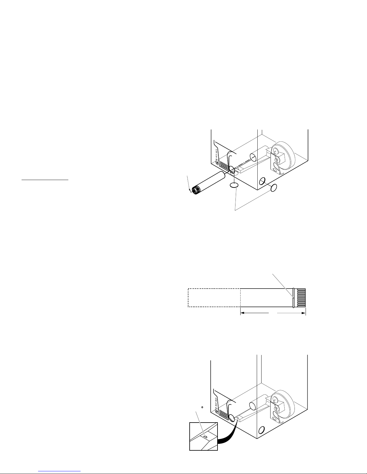
Dryer Exhaust to Left or Bottom of Cabinet
WARNING: Protect your hands and arms from
sharp edges when working inside the cabinet.
1. Detach and remove the bottom or left-side
knockout as desired.
Remove
Screw
And Save
Remove Desired
Knockout (One Only)
GEA00558
Bathroom or Bedroom Installation
• The dryer must be vented to the outdoors. See
the “Exhaust Information” section.
• The installation must conform with local codes
or, in the absence of local codes, with the
National Fuel Gas Code, ANSI Z223.
Mobile or Manufactured Home Installation
• Installation must conform to the Manufactured
Home Construction & Safety Standard, Title 24,
Part 32-80 or, when such standard is not applicable, with the American National Standard for
Mobile Home, ANSI/NFPA No. 501B.
• The dryer must be vented to the outdoors with
the termination securely fastened to the mobile
home’s structure. See the “Exhaust Information”
section.
• The vent must not be terminated beneath a
mobile or manufactured home.
• The vent duct material must be metal.
• Kit 14-D3A6-33 must be used to attach the
dryer securely to the structure.
• The vent must not be connected to any other
duct, vent, or chimney.
• Do not use sheet metal screws or other refas-
2. Remove and save the screw inside the dryer
exhaust duct. Pull the duct out of the dryer.
3. Cut the duct as shown and keep portion A.
Fixing Hole
AB
9"
GEA00559
4. Through the rear opening, locate the tab in the
middle of the appliance base. Lift the tab to
approximately 45° using a flat-blade screwdriver.
Bend
Tab 45
GEA00560
– 6 –
Page 9
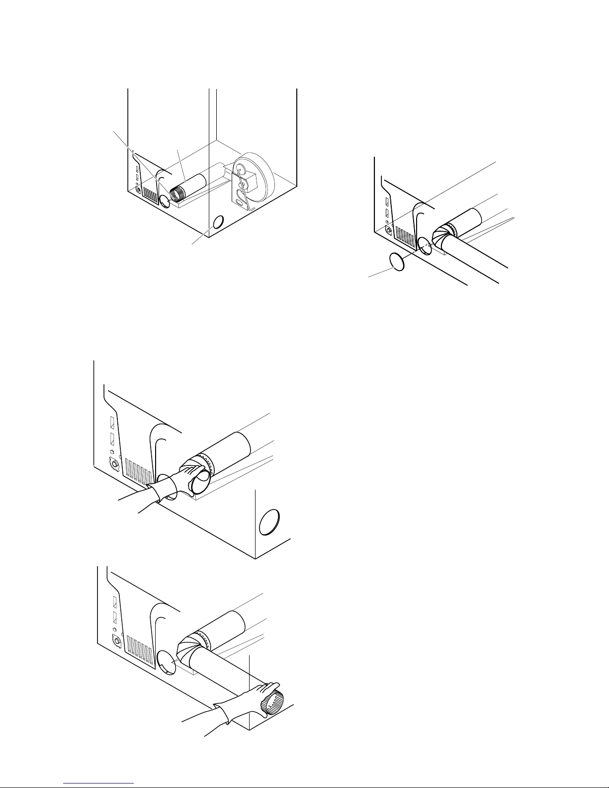
5. Reconnect the cut portion (A) of the duct to
the blower housing. Ensure the fixing hole is
aligned with the tab in the base.
Fixing
Hole
Portion "A"
8. Connect standard metal elbows and ducts to
complete the exhaust system.
Caution: Never leave the rear opening uncovered.
Install a cover plate.
9. Cover back opening with a plate (Kit
WE1M454) that is available from your local
service provider.
Left Side
Exhaust
GEA00561
6. Use the previously saved screw to secure the
duct in place through the tab on the the appliance base.
7. For exhaust to the side of the cabinet, insert
the elbow and the duct.
Insert 4" Elbow
Through Rear Opening
Plate
(Kit WE1M454)
10. Place the dryer in its final location.
GEA00564
Insert 4" Exhaust
Through Side Opening
GEA00562
GEA00563
– 7 –
Page 10

Operating Characteristics
Note: Not all models have the same features. Your
model may vary from those discussed in this
manual.
Basic Dryer Operation
The L3 Dryer contains both sensor dry and timed
dry options.
• The six
desired dryness level as measured by the rod
voltage signal. Each cycle’s settings control the
heated dry time and specific cooldown time. At
the end of cooldown, the machine stops the
drying operation and signals the end of the
cycle.
• During
dries the load for the specified time, including
extended tumble time (if selected). At the end of
the selected time, the dryer ceases to tumble
and heat the clothes, and signals the end of the
cycle.
Note: Only one sensor or timed dry cycle can be
selected at any time. A new cycle selection will
override the previous one.
SENSOR DRY cycles
TIMED DRY cycles
, the dryer tumble-
dry clothes to a
voltage signal.
• When the load reaches the Damp threshhold,
the dryer calculates the required remaining time
to dry the load to the specified dryness level.
The estimated remaining time appears in the
display, the countdown resumes, and the Sens-
ing LED turns OFF. The countdown continues until
the end of the cycle, including cooldown time.
• At the end of the cycle, the unit stops drying, the
Sensor Dry LED turns OFF, the display reads
“00,” and the Clean Lint Filter LED turns ON.
• The display and Clean Lint Filter LED turn OFF
when the user 1) opens the door, 2) presses
Stop/Cancel, or 3) starts another cycle selection.
Speed Dry
When the Speed Dry button is pushed, the letters
“SP” appear in the digital display. When the user
presses Start/Pause, the display enters Variable
Speed Racetrack mode until the Damp threshhold
is calculated, then it shows “SP” for the entire
cycle.
One Touch Sensor Dry Cycles
Cottons, Mixed Loads, Easy Care/Perm Press,
Knits/Sweaters, and Delicates
These buttons use predetermined dryness levels
(either Dry or Less Dr y) and temperatures (Extra
Low to High/[Regular]) to dry clothes. The Sensor
Dry LED is ON until the end of the cooldown
period.
The cycles proceed as follows:
• Pressing a cycle button will cause the display to
show the default numbers for that cycle.
• Once the user presses the Start/Pause button,
the display begins the normal countdown, and
the Sensor Dry LED turns ON.
• When the default minimum time for the selected
cycle is reached, the display enters Variable
Speed Racetrack mode and the Sensing LED
begins to flash. Four speed levels are available;
the speed will be determined by the sensor rod
One T ouch Timed Dry Cycles
DRYEL™, De wrinkle, and Air Dry
These buttons use Medium or (for Air Dry) no heat
and a specified time period to tumble and dry loads.
The
DRYEL™
runs for 20 minutes, and Air Dry runs for 10 minutes.
The Timed Dry LED turns ON until the end of the
cycle (including cooldown), then the Clean Lint
Filter LED turns ON as described earlier.
DRYEL™ System
DRYEL™ helps “dry clean only” clothes look and
smell clean and fresh. While not a complete dry
cleaning system, DRYEL™ uses a perfumed pad
and nylon bag to eliminate odors (such as smoke
and perspiration) and wrinkles from clothes. The
DRYEL™ kit, available in retail stores, also includes a spot remover for removing small stains.
Caution: Using any other bag with the DR YEL™
system may damage the clothes or the L3 Dryer.
cycle runs for 30 minutes, Dewrinkle
– 8 –
Page 11

Due to the DRYEL™ pad, clothes may be damp
when the dryer cycle is completed; this is normal.
Note: DRYEL™ is not a replacement for
professional dry cleaning. Fabrics with large or
heavy stains may not come clean using this
system. Also, this system will not press clothes.
Custom Cycles
Custom Cycle buttons allow the consumer to
create two additional One Touch Dry Cycles.
These cycles can be either
, and can include any dryness level, time
Dry
Sensor Dry
or
Timed
period, heat setting, or option desired.
updated. However, heater settings do not change;
default heater settings will be performed.
Start/Pause
When this button is pushed either for the first time
or after the Stop/Cancel button is pushed, the
display defaults to the last cycle run and the Start/
Pause button’s LED light flashes 0.5 seconds ON
and 0.5 seconds OFF, indicating “Action Needed
to Start.”
If the button is pushed after a cycle is selected,
the machine starts per the selected cycle and
options unless the door is open. If the door is
open, the button flashes and no action occurs.
Dryness Levels
Note: Dryness Level buttons are locked out for
One Touch Timed Dry Cycles.
Four dryness levels, including More Dry, Dr y, Less
Dry, and Damp, are available. When a Dryness
Level button is pushed, no other button is affected
with one exception. When a Dryness Level button
is pushed after a One Touch Timed Dry Cycle
button or the Antibacterial button has been
selected, the new dryness setting appears in the
display, and the time matr ix is updated. However,
the heater setting does not change; default heater
settings will be performed.
Timed Dry Only
When any Timed Dry Only button is pushed, the
cycle defaults to a Medium heat setting and no
specific Dryness Level.
The Timed Dry LED turns ON until the end of the
cycle (including cooldown), then the Clean Lint
Filter LED turns ON as described earlier.
Heat Setting
(High/[Regular], Medium, Low, and Extra Low)
Note: Heat Setting buttons are locked out for the
Air Dry cycle.
When any Heat Setting button is pushed, that
option will be selected. No other button will be
affected with one exception. When a Heat Setting
button is pushed after the Knits/Sweaters,
Delicates, Dryel, Dewrinkle, or Antibacterial cycle
has been selected, the new temperature setting
appears in the display and the time matrix is
On initial power-up, either from the factor y or after
a power outage, pressing the Start/Pause button
displays the default settings for the Cotton Sensor
Dry cycle.
If the button is pushed in midcycle, the unit enters
Pause mode. Drying operation stops and the
Start/Pause button’s LED flashes. Pressing the
button again resumes drying operations.
Stop/Cancel
Pushing this button deactivates all selections, and
all LEDs turn OFF. If the machine is running when
this button is pushed, the machine turns OFF.
Idle Mode
The idle mode has no LEDs or relays lit; the
control is waiting for the consumer to touch a
keypad or switch.
Power Outage
In the event of a power outage, and the dryer is in
idle mode, press any key except Stop/Cancel to
set the dryer in the Cotton Sensor Dry cycle.
Change options as needed.
Options
Beeper
Activating this option allows the beeper to sound
(two short tones followed by a long tone) at the
end of a cycle. The beeper signals every 2 minutes up to four times unless the door is opened,
– 9 –
Page 12

the beeper is deactivated, or the Stop/Cancel
button is pressed.
When the Beeper button is pushed during a
deactivated state, the beeper turns ON at high
volume, the LED on the Beeper button turns ON,
and the beeper sounds. Pushing the Beeper
button again deactivates the option and turns OFF
the LED light.
Extend Tumble
Pushing the Extend T umble button activates the
option; pushing the button a second time deactivates the option. The Extended T umble LED is
ON during the extended tumble care portion of the
cycle.
Add Time
Pushing the Add Time button once adds 10
minutes to the current cycle’s drying time. If the
button is pushed after the Stop/Cancel button, a
default 10-minute dry cycle activates at Medium
heat.
Antibacterial
Note: Use this option only with the Cottons or
Mixed Loads cycles. Do not use this cycle for
delicate fabrics.
Pushing the Antibacterial button adds high heat
to a portion of the current drying cycle. The Timed
Dry LED remains ON until the end of the cycle, at
which time the Clean Lint Filter LED turns ON.
Commercial Dryer
The commercial dryer uses the keypad model
control design. It has fewer keypad options and is
designed for apartment or commercial noncoin
applications.
– 10 –
Page 13

Notes
– 11 –
Page 14

Electronic Controls
The L3 dryer offers the convenience of starting your wash loads with easy one touch cycles. One
simple selection automatically sets your Dryness Level and Heat Setting. Then just press Start.
Model Type 592
O
NE TOUCH
Sensor Dry Cycles
COTTONS
M
IXED
L
OADS
E
ASY CARE
PERM PRESS
KNITS
SWEATERS
D
ELICATES
SPEED
DRY
Commercial Model Type 450
D
W
C
SENSOR DRY
E
RINKLE
USTOM
PRESS 3 SEC TO STORE
1
C
A
IR
D
USTOM
RY
2
D
RYNESS
L
EVEL
M
ORE
D
D
L
ESS
D
D
AMP
SENSOR DRY
C
H
EAT
MIN
MIN
MIN
MIN
40
30
20
10
SETTING
(REGULAR)
M
CLEAN LINT FILTER
T
IMED DRY ONLY
80
RY
RY
RY
MIN
70
MIN
60
MIN
50
MIN
EXTENDED TUMBLE SENSING
YCLE STATUS
H
EDIUM
L
E
XTRA
L
OW
IGH
OW
O
PTIONS
B
E
XTEND
T
UMBLE
T
B
ACTERIAL
EEPER
A
DD
IME
A
NTI
S
TART
PAUSE
S
TOP
CANCEL
E
ST. TIME REMAINING
GEA00567
Description
A keypad electronic dryer control has replaced the
electronic/rotary selection control to improve ease
of use and serviceability.
The L3 electronic control consists of a printed
circuit board, a transformer, and housing.
GEA00566
Estimated Time Remaining
When a cycle is chosen, the Dual Seven Segment
Display (DSSD) displays an estimated time for the
drying cycle.
The default numbers initially displayed for Sensor
Dry cycles will change based on the previous
cycle run. The display will show the selected time
for the Timed Dry cycle; 30 minutes for the Dryel
cycle; 20 minutes for the Dewrinkle cycle; and 10
minutes for the Air Dry cycle.
– 12 –
Page 15

Field Service Mode
To enter the Field Service Mode, disconnect then
reconnect the electrical power at the wall outlet.
Within 30 seconds, simultaneously press and hold
the Cottons and Start/Pause buttons for 3 seconds. The unit will start and run, but continue to
hold the buttons until the diagnostics mode is
entered. As soon as the test cycle is entered, the
Dual Seven Segment Display (DSSD) displays, in
sequence, the letters Fd (Field Service Diagnostics), EL or GA (for electric or gas dryer type), and
the EEPROM version number. Wait for the DSSD
to turn OFF before proceeding with testing.
To index to the next test position, press the Mixed
Loads button. To return to the previous test
position, press the Easy Care/Perm Press button.
The following tables give the functions for the
subsequent positions.
Sensor Rods Check: S0 displays if sensor rods
are open circuit. If a problem exists, E2 displays.
Touch sensor rod with your hand for 20 seconds.
SS displays if capacitor is discharging properly.
Motor Check: Motor switches ON and DSSD
displays Sn.
Heater 1 Check: Tur ns ON heater 1 and displays
H1.
Heater 2 Check: Tur ns ON heater 2 and displays
H2.
Door Status Check: Displays d0 for door open or
dC for door closed.
Test Sequence , Gas Dryer
noitisoP
DSSD
tuptuO
noitcnuF
Test Sequence , Electric Dryer
noitisoP
DSSD
tuptuO
laitinI-0dFedoMcitsongaiDdleiF
laitinI-0LEcirtcelE
laitinI-0# rebmuNnoisreVMORPEE
10ErorrEoN,rotsimrehT
11ErotsimrehTdraoBrororrE
20SlamroN,*tiucriCnepO,sdoR
22EdetrohS,*melborPtiucriC,sdoR
3nSrotoMNOsehctiwS
41HretuO,NOsnruT1retaeH
52HrennI,)FFO1(NOsnruT2retaeH
laitinI-0dFedoMcitsongaiDdleiF
laitinI-0AGsaG
noitcnuF
laitinI-0# rebmuNnoisreVMORPEE
20SlamroN,*tiucriCnepO,sdoR
22EdetrohS,*melborPtiucriC,sdoR
3nSrotoMNOsehctiwS
4n1NOsnruTretingI
5n2NOsnruTyaleReraCartlU
60d)desolCrooD=Cd(nepOrooD
* See Rods Table
Sensor Rods Check: S0 displays if sensor rods
are open circuit. If a problem exists, E2 displays.
Touch sensor rod with your hand for 20 seconds.
SS displays if capacitor is discharging properly.
60d)desolCrooD=Cd(nepOrooD
* See Rods Table
Thermistor Check: E0 displays if no error is in
thermistor circuit. If an error exists, E1 displays. To
verify thermistor, a resistance range of 100K ohms
+/- 10% @ 77 °F should be found between pins 5
and 6 of female connector CN4 at the right side of
the transformer.
Motor Check: Motor switches ON and DSSD
displays Sn.
Igniter Check: Tur ns ON igniter and displays 1n.
Ultra Care Check: Turns ON Ultra Care relay and
displays 2n.
Door Status Check: Displays d0 for door open or
dC for door closed.
– 13 –
Page 16

Sensor Rod Circuit Description
Sensor Rods Table
The moisture-sensing rods are part of a circuit
that is designed to utilize a low-voltage capacitor
that charges to 5 V when the circuit is open, and
discharges to 1 V when the circuit is shorted. The
gap in the circuit is the space between the rods.
When the wet clothes touch the two rods, they
create a short, which discharges the capacitor.
When the clothes become dry, they cannot short
the circuit and the charge across the capacitor
builds to 5 V. A voltage of 1 V across the capacitor
read by the PCB indicates wet clothes. As the
clothes are dried, the voltage increases, and
finally 5 V across the capacitor indicate completely
dry clothes.
In the diagnostics mode, a code of S0 indicates a
normally open circuit (the capacitor is charged
properly). The code E2 indicates a shorted capaci-
tor or some other problem on the board. To check
the discharging of the capacitor, touch the rods
with your hands, shorting the two rods for at least
5 seconds. The S0 will change to SS, indicating
that the capacitor discharged properly. No change
from S0 indicates that either the rods are not
connected to the board or there is some other
problem on the board.
Note: If you want to repeat the test, wait for at
least 45 seconds to fully charge the capacitor.
tuptuODSSD
SSotOS)KOsdoR(tluaFoN
SSot2EskaeLroticapaC
2Eot2EtiucriCotdetcennoCtoN
sisongaiD
The Field Service Mode can be exited in three
ways:
1. Press the Stop/Cancel keypad.
2. Unplug the unit.
3. Control automatically exits test mode after 30
minutes.
Checking Power to the PCB
To check the presence of 240 V at the board, put
the dryer in Air Dry cycle (the motor will run with
no heat).
• If the
outer heating element is OK, there will be
240 V between tap 16 (L2 through coil) and tap
8 (L1).
• If the
inner heating element is OK, there will be
240 V between tap 10 (L2 through coil) and tap
8 (L1).
To Enter Field Service
Diagnostic Mode
Begin
Press and hold
Start/Pause and
Cottons buttons.
Release Start/Pause
button and Cottons
button.
Field Service
Mode
Press Stop/
Cancel button.
To Exit Field Service
Diagnostic Mode
Field Service
Mode
-
30 Min.
Timeout
from Start
of Mode
Idle
Loss of
Power to
Control
GEA00535
– 14 –
Page 17

Dryer control panel.
You can locate your model number on the label on the front of the dryer, behind the door.
Model Type 592
Model Type 591
O
NETOUCH
Quick Start Guide
• Clean lint filter
• Add clothes
• Select dry cycle
• Check dryness level
• Check heat setting
• Close door
• Push
START
Your new dryer offers the convenience of starting your dryer loads with our easy
ONET
OUCH
cycles. Make one simple
selection, and your
DRYNESS LEVEL
and
HEAT SETTING
are automatically set. Then all you have to do is press
START
.
Easy ONET
OUCH
Cycles.
Control Settings
Model Type 592
O
NE TOUCH
Sensor Dry Cycles
COTTONS
M
IXED
L
OADS
EASY CARE
PERM PRESS
K
S
WEATERS
DELICATES
Commercial Model Type 450
NITS
SPEED
DRY
SENSOR DRY
D
E
A
IR
W
RINKLE
D
RY
C
USTOM
C
USTOM
1
PRESS 3 SEC TO STORE
D
RYNESS
L
EVEL
M
D
D
L
D
D
2
SENSOR DRY
C
TIMED DRY ONLY
ORE
ESS
AMP
RY
RY
RY
80
MIN
70
MIN
60
MIN
50
MIN
EXTENDED TUMBLE SENSING
YCLE STATUS
40
MIN
30
MIN
20
MIN
10
MIN
HEAT
SETTING
(REGULAR)
M
CLEAN LINT FILTER
H
EDIUM
L
E
XTRA
L
OW
OPTIONS
B
IGH
E
T
OW
B
EEPER
XTEND
UMBLE
A
DD
T
IME
A
NTI
ACTERIAL
S
TART
PAUSE
S
TOP
CANCEL
E
ST. TIME REMAINING
GEA00567
GEA00566
– 15 –
Page 18

ONET
OUCH
selections.
PRESS... AUTOMATICALLY SELECTS... THEN PRESS...
Changing the automatic settings.
For cottons and most linens.
For loads consisting of
cottons and poly-blends.
For wrinkle-free and
permanent press items.
For knits and sweaters with fabric care
labels that say “Machine Dry”.
For lingerie and special care fabrics.
For small loads that are needed in a hurry,
such as sport or school uniforms. Can also
be used if the previous cycle left some
items damp, such as collars or waistbands.
O
NE
T
OUCH
cycles use the
Sensor Dry
feature, which continuously monitors the amount of moisture
in the load and stops the dryer when the clothes are dry.
NOTE: During SPEED DRY
you will see:
Y ou can change any of the automatic settings by simply pressing the desired pads.
– 16 –
Page 19

About drying cycles.
DRYEL™(on some models)
This feature is designed for use with the DRYEL™“dry clean only” fabric care system.
See product package for directions.
For questions or issues related to the use and performance of DRYEL
™
, call
1-800-214-8913, or visit the DRYEL
™
website at www.dryel.com.
Automatic DRYEL™settings:
DEWRINKLE
Use this feature to remove wrinkles from items that are dry or slightly damp.
Automatic DEWRINKLE settings:
AIR DRY
Use this feature to tumble items without heat.
CUSTOM 1 and CUSTOM 2 (on some models)
Set up your favorite combination of settings and save them here for one-touch recall.
These custom settings can be set while a cycle is in progress.
To store a custom combination of settings:
1. Select a
ONE TOUCH
setting.
2. Change
DRYNESS LEVEL
and
HEAT SETTING
to fit your needs.
3. Select any drying
OPTIONS
you want.
4. Press and hold the
CUSTOM 1
or
CUSTOM 2
pad for three seconds to store
your selection. A beep will sound and the pad will light up.
To recall your stored combination:
Press the
CUSTOM 1
or
CUSTOM 2
pad, then press
START/PAUSE
.
To reprogram the CUSTOM settings:
Repeat steps 1-4 above.
Automatic AIR DRY settings:
– 17 –
Page 20

About dryness levels.
MORE DRY
Use for heavy-duty fabrics.
DRY
Use for a normal dryness level suitable for most loads. This is the preferred cycle for
energy saving.
LESS DRY
Use for lighter fabrics.
DAMP
For leaving items partially damp.
HIGH (Regular)
For regular to heavy cottons.
MEDIUM
For synthetics, blends and items labeled permanent press.
LOW
For delicates, synthetics and items labeled
Tumble Dry Low
.
EXTRA LOW
For lingerie and special-care fabrics.
About heat settings.
To use TIMED DRY ONLY:
1. Select the drying time.
2. Select the
HEAT SETTING
.
3. Select any
OPTIONS
. (
NOTE:
The
ANTI BACTERIAL
option is not available with
TIMED DRY ONLY
cycles.)
4. Close door.
5. Push
START
.
About timed dry only cycles.
– 18 –
Page 21

About controls features.
START/PAUSE
■
Press twice to select the last cycle you used and start the dryer.
■
If you have selected a new cycle, press once to start the cycle.
■
If the dryer is running, press once to interrupt the cycle; press again to continue
the cycle.
STOP/CANCEL
■
This pad should
not
be used to interrupt or pause a cycle.
■
Pressing this pad will cancel the current settings and the settings will be lost.
Estimated Time Remaining
Each time the dryer is used, it “learns” what types of loads you dry most often.
It takes this data and determines the approximate time it will take the load to dry.
As the cycle begins, you will see the approximate total cycle time in the display.
Then “racetrack lights” will flash in the display, in a clockwise direction, and the
SENSING
light will flash. This means the dryer is continuously monitoring the amount
of moisture in the load. The racetrack lights will continue until the dryer senses a low
level of moisture in the load. At that point, the dryer will calculate and display the
approximate time remaining.
“Racetrack lights”
– 19 –
Page 22

About cycle options.
BEEPER
Alerts you that the cycle is complete. The beeper will continue to sound every two
minutes for the next 6 minutes, until the clothes are removed. The clothes should
be removed when the beeper goes off so wrinkles won’t set in.
EXTEND TUMBLE
Minimizes wrinkles by adding approximately 20 minutes of no-heat tumbling after
clothes are dry. The beeper will sound every 90 seconds to remind you to remove
the clothes. The
EST. TIME REMAINING
display will show 00.
ADD TIME
This option can be used to extend drying time at the end of any cycle. 10 minutes is
added each time the pad is pressed.
ANTI BACTERIAL (on some models)
This option can only be used with the
COTTONS
or
MIXED LOADS
cycles.
This option reduces certain types of bacteria by 99.9%, including: Staphylococcus
aureus, Pseudomonas aeruginosa, and Klebsiella pneumoniae*. The anti-bacterial process
occurs when high heat is used during a portion of the drying cycle.
NOTE:
Do not use this cycle on
delicate
fabrics.
* The Anti-Bacterial Cycle is Certified by NSF International (formerly National Sanitation
Foundation) to NSF Protocol
P9 Sanitization Performance of Residential Clothes Dryers.
NSF
®
NSF Protocol P9
Sanitization Performance of
Residential Clothes Dryers
– 20 –
Page 23

TIMED DRY
This light comes on when
AIR DRY, DEWRINKLE, DRYEL (on some models)orTIMED DRY
ONLY
is selected.
About cycle status.
These cycle status indicator lights display what part of the cycle the dryer is in and remind you to clean the lint filter.
SENSOR DRY
This light comes on when a
ONET
OUCH
Sensor Dry Cycle
is selected.
SENSING
Sensor Dry Cycles provide greater drying accuracy than standard machines,
resulting in shorter dry times and better clothes care. The
SENSING
light will
flash and “racetrack lights” will flash in the display while the dryer is monitoring
the amount of moisture remaining in the clothes. When the
SENSING
light goes
out, the dryer will calculate and display the approximate time remaining.
EXTENDED TUMBLE
This light comes on when the
EXTEND TUMBLE
option is selected.
CLEAN LINT FILTER
This light is a reminder to clean the lint filter. It comes on at the end of a cycle and
goes off when the door is opened.
“Racetrack lights”
– 21 –
Page 24

Removal and Replacement
Remove Electronic Control Board
1. Remove 4 screws from the top of the
backsplash and rotate the top forward.
2. Tag and remove 11 electrical connections.
Note: Remove and retain the model selector
harness plug for reassembly.
3. Remove 2 screws (1/4-in.) from the control
board.
Caution: To prevent electrostatic discharge,
ground yourself to the dryer cabinet, or use an
ESD wristband.
4. Remove the electronic control board.
Note: When reassemb ling, align the LEDs with
the appropriate control panel indicators.
5. Reverse the above procedure to reinstall.
Remove 4 Screws
GEA00545
Electrical
Electrical
Connections
Connections
Screws
Screws
Model
Model
Selector
Selector
Harness
Harness
GEA00544
– 22 –
Page 25

Notes
– 23 –
Page 26

Schematics
WARNING
POWER MUST BE DISCONNECTED BEFORE SERVICING THE APPLIANCE.
Terminal Layout on PCB, Electric Model DPSE592EA0
BROWN/WHITE
6 1
BROWN
Note: The numbers in the drawing of the PCB
above correspond to the numbers on the
schematic on page 25.
BROWN
BLUE
8
7
GRAY
YELLOW
TERMINAL LAYOUT ON PCB, ELECTRIC DRYER
BROWN
BLACK
2A
9
10
N
PURPLE
16
BLACK
J
L1
ORANGE
ORANGE
MODELS WIRE COLOR
DPSE592 WHITE 1-6
DPSE591 YELLOW, RED 1-3, 4-5
DNCD450 BLACK, YELLOW 1-2-3, 4-5
BLUE
BLUE
GRAY PINK
MODEL SELECTOR CONNECTOR MATRIX CHART
6543 1
WHITE
MODEL SELECTOR
TERMINAL POSITION
GEA00573
Terminal Layout on PCB, Gas Model DPSE592GA0
BROWN/WHITE
6 1
BROWN
BLUE
PURPLE
YELLOW
Note: The numbers in the drawing of the PCB
above correspond to the numbers on the
schematic on page 26.
2A
8
10
7
ORANGE
YELLOW/BLACK
TERMINAL LAYOUT ON PCB, GAS DRYER
BLACK
BLACK
N
169
J
YELLOW/BLACK
L1
BLACK
GRAY PINK
MODEL SELECTOR CONNECTOR MATRIX CHART
MODELS WIRE COLOR TERMINAL POSITION
DPSE592 ORANGE, WHITE 1-3, 5-6
DPSE591 YELLOW, WHITE 1-4, 5-6
DNCD450 GRAY, BLACK 1-2, 4-5-6
43 1
WHITE
MODEL SELECTOR
GEA00572
Refer to microfiche for specific model information.
– 24 –
Page 27

L3 Dryer - Electric Model
L1
Caution: Label all wires prior to disconnection when
servicing the controls. Wiring errors can cause
improper and dangerous operation. Verify proper
operation after servicing.
N
L2
RED
ORANGE
SAFETY
THERMO LEFT
TRANSFORMER
L1
ORANGE
THERMO
HI-LIMIT
ELECTRONIC DRYER
POWER BOARD
INLET
BIAS
RELAY
K3-no
DRUM
OUTLET
BLUE
(ULTRACARE)
OUTER COIL
RELAY (15A)
K4-no
BLACK
PURPLE
OUTLET
BIAS RELAY
POWER/START
K2-no
RELAY
K1-no
G5S
G8P
1 6 8 7 J 16 9 10 2A
BROWN BROWN
RIGHT
BROWN/WHITE
ORANGE
INNER COIL
RELAY (15A)
K5-no
G8PG8PG5S
BLACK
YELLOW
GRAY
BLUE
YELLOW
PURPLE
N
WHITE
1
PINK
3
GRAY
4
BLUE
5
BLUE
6
THERMISTOR ASSEMBLY
IDLER SWITCH
CONTROL
9K9K
INLET
YELLOW
PINK
GRAY
LOWER ROD MOV
UPPER ROD MOV
DRUM/BLOWER MOTOR
M6
RED
YELLOW
GRAY
WHITE
DOOR
SWITCH
NC
WHITE BLACK BLACK/RED
COM
NO
GREEN
BROWN/YELLOW
START
RUNM5
BLUE
SOLDER TRACES ON PC BOARD
GANGED SWITCH
COMMERCIAL OMITTED
LEGEND
OVERLOAD
PROTECTOR
M4
BLACK
DRUM LAMP
M1
M2
INNER COIL 19.2
PURPLE
HEATER HOUSING
OUTER COIL 19.2
GEA00552
Note: See schematic for proper switch connections.
1. Heater coil resistance is shown on the wir ing schematic. Check for infinite resistance between
any heater terminal and dryer cabinet. Heater failure could result from low airflow caused by
improper sealing, kinked or excessive ducting, or excessive line voltage.
2. Other factors contributing to long dr y times or clothes conditions include load size, number of
large or bulky items, ambient temperature, room size (if not exhausted outdoors), wetness of
clothes, and washer rinse temperature.
3. Small loads (less than 3 lb) may develop static, causing clothes to cling to the drum surface
(no tumble) and resulting in wrinkles, shrinkage, or melting. Use a fabric softener in the
washer or dryer, or add two large bath towels to act as a buffer when drying.
– 25 –
Page 28

L3 Dryer - Gas Model
L1
Caution: Label all wires prior to disconnection when
servicing the controls. Wiring errors can cause
improper and dangerous operation. Verify proper
operation after servicing.
N
BLACK
TRANSFORMER
BLACK
BLACK
OUTLET/ULTRACARE
BIAS RELAY
POWER/START
LEGEND
SOLDER TRACES ON PC BOARD
GANGED SWITCH
COMMERCIAL OMITTED
K2-no
RELAY
K1-no
G8P
BLACK
BROWN/WHITE BLACK
ELECTRONIC DRYER
POWER BOARD
BIAS
RELAY
K3-no
YELLOW/BLACK
TRIMMER
YELLOW YELLOW/BLACK
GAS VALVE
RELAY
K4-no
9K
DRUM
OUTLET
ULTRACARE RELAY
(GENTAL HEAT)
K5-no
G8PG8PG5SG5S
ORANGE
BROWN/WHITE
BLACK
BLACK WHITE
N
1
3
4
5
9K
CONTROL
INLET
BLACK
9K
6
IDLER SWITCH
PURPLE
ORANGEORANGE
2AL1 1016 97861J
BROWN
PURPLE
BLUE
BLUE
PINK
GRAY
WHITE
DRUM LAMP
YELLOW
PINK
GRAY
SAFETYULTRACARE
LOWER ROD MOV
UPPER ROD MOV
RED
BOOSTER
YELLOW
SAFETY
DOOR SWITCH
GREEN
DRUM/BLOWER MOTOR
M6
START
M5 M4
RUN
OVERLOAD
PROTECTOR
PURPLE
IGNITOR DETECT
COIL
COIL
MAIN
COIL
NC
COM
NO
BROWN/YELLOW
GAS VALVE
WHITE
BROWN/YELLOW
YELLOWBLACK
M1
M2
GEA00550
Note: See schematic for proper switch connections.
1. Other factors contributing to long dry times or clothes conditions include load size, number of
large or bulky items, ambient temperature, room size (if not exhausted outdoors), wetness of
clothes, and washer rinse temperature.
2. Small loads (less than 3 lb) may develop static, causing clothes to cling to the drum surface
(no tumble) and resulting in wrinkles, shrinkage, or melting. Use a fabric softener in the
washer or dryer, or add two large bath towels to act as a buffer when drying.
– 26 –
Page 29

Notes
– 27 –
Page 30

Troubleshooting Flowchar ts
L3 Dryer - Electric Model
Dryer
Proper voltage to
Dryer.
Yes
Enter field service
mode (disconnect/
reconnect power, then
press and hold
and
Cotton
Unit will start
and run. Continue to
hold buttons until
diagnostics mode is
Start
buttons).
entered.
No
Test
Mode.
House fuse, breaker,
wall outlet problem.
DSSD output displays
Fd, EL
, and EEPROM
version number.
Check error codes.
Press
Mixed Loads
button - DSSD output
displays error codes for
existing errors.
Press
Stop
to exit field
service mode.
E0
Thermistor, No Error.
Thermistor Error or
E1
Sensor Rods, Open
S0
Circuit, Normal
Sensor Rods, Circuit
E2
Problem, Shorted
Sn
Motor Switches ON
Heater 1 Turns
H1
Heater 2 Turns ON
H2
(1 OFF), Inner
Board.
ON, Outer
Touch rods
with hand for
20 seconds.
Touch rods
with hand for
20 seconds.
No Fault, Rods OK.
SS
Capacitor Leaks -
SS
Replace capacitor.
Not Connected to
E2
Circuit - Check
connection.
dO
dC
Door Open
Door Closed
– 28 –
Page 31

L3 Dryer - Gas Model
Dryer
Proper voltage to
Dryer.
Yes
Enter field service
mode (disconnect/
reconnect power, then
press and hold
and
Cotton
Unit will start
and run. Continue to
hold buttons until
diagnostics mode is
Start
buttons).
entered.
No
Test
Mode.
House fuse, breaker,
wall outlet problem.
DSSD output displays
Fd, GA
, and EEPROM
version number.
Check error codes.
Press
Mixed Loads
button - DSSD output
displays error codes for
existing errors.
Press
Stop
to exit field
service mode.
Sensor Rods, Open
S0
Circuit, Normal
Sensor Rods, Circuit
E2
Problem, Shorted
Sn
Motor Switches ON
1n
Igniter Turns ON
Ultra Care Relay
2n
dO
Turns ON
Door Open
Touch rods
with hand for
20 seconds.
Touch rods
with hand for
20 seconds.
No Fault, Rods OK.
SS
Capacitor Leaks -
SS
Replace capacitor.
Not Connected to
Circuit - Check
E2
connection.
dC
Door Closed
– 29 –
Page 32

Illustrated Parts Breakdown
Exploded parts views and list for Model DPSE592EA0.
Refer to microfiche for specific model information.
– 30 –
Page 33

Exploded parts views and list for Model DPSE592EA0.
Refer to microfiche for specific model information.
– 31 –
Page 34

Exploded parts views and list for Model DPSE592EA0.
Refer to microfiche for specific model information.
– 32 –
Page 35

Exploded parts views and list for Model DPSE592EA0.
Refer to microfiche for specific model information.
– 33 –
Page 36

Exploded parts views and list for Model DPSE592EA0.
Refer to microfiche for specific model information.
– 34 –
Page 37

Exploded parts views and list for Model DPSE592EA0.
Refer to microfiche for specific model information.
– 35 –
Page 38

Exploded parts views and list for Model DPSE592EA0.
Refer to microfiche for specific model information.
– 36 –
Page 39

Quiz
1. How do you get into the Field Service Mode for
the Wizard Dryer?
a) Press & hold “Start/Pause” button for 3
seconds
b) Press & hold “DeWrinkle/Air Dry” buttons for
3 seconds
c) Press & hold “Mixed Loads” & “Start/Pause”
buttons together for 3 seconds
d) Press & hold “Start/Pause” button, then
press & hold “Cottons” button for 3 seconds
within 30 seconds of power on
e) None of the above
2. What function does Step 3 indicate in the Field
Service Mode for the Wizard Dryer?
a) Thermistor check
b) Sensor rods check
c) Motor check
d) Heater 1 check
e) Heater 2 check
3. The “Dryel” feature of the Wizard Dryer allows
customers to actually dry clean their garments.
T or F
6. To check the rod sensors, you can place your
fingers across the rods and you should measure 5 VDC at the control board 6-pin plug #5
& #6. T or F
7. The thermistor should read approximately
100K ohms at room temperature. T or F
8. During a medium heat cycle, which bias contacts are activated?
a) Outlet bias
b) Inlet bias
c) Outlet & inlet bias
d) None of the above
9. What voltage is applied to the bias heater when
active?
a) 12 VDC
b) 14 VDC
c) 120 VAC
d) 0 VAC
e) 0 VDC
4. An “E1” code for the Wizard Dryer signifies that
the thermistor is either open or shorted. T or F
5.) There is no “Model Selection Plug” for the
Wizard Dryer. T or F
Exploded parts views and list for Model DPSE592EA0.
Refer to microfiche for specific model information.
10. Which components are activated during the
Field Service Mode for the Wizard Electric
Dryer?
a) Thermistor, motor, heater 1, and heater 2
b) Motor, heater 1, heater 2, and drum light
c) Motor, heater 1, and heater 2
d) Motor, igniter, and ultra-care relay
– 37 –
Page 40

Exploded parts views and list for Model DPSE592EA0.
Refer to microfiche for specific model information.
– 38 –
 Loading...