

Page 1
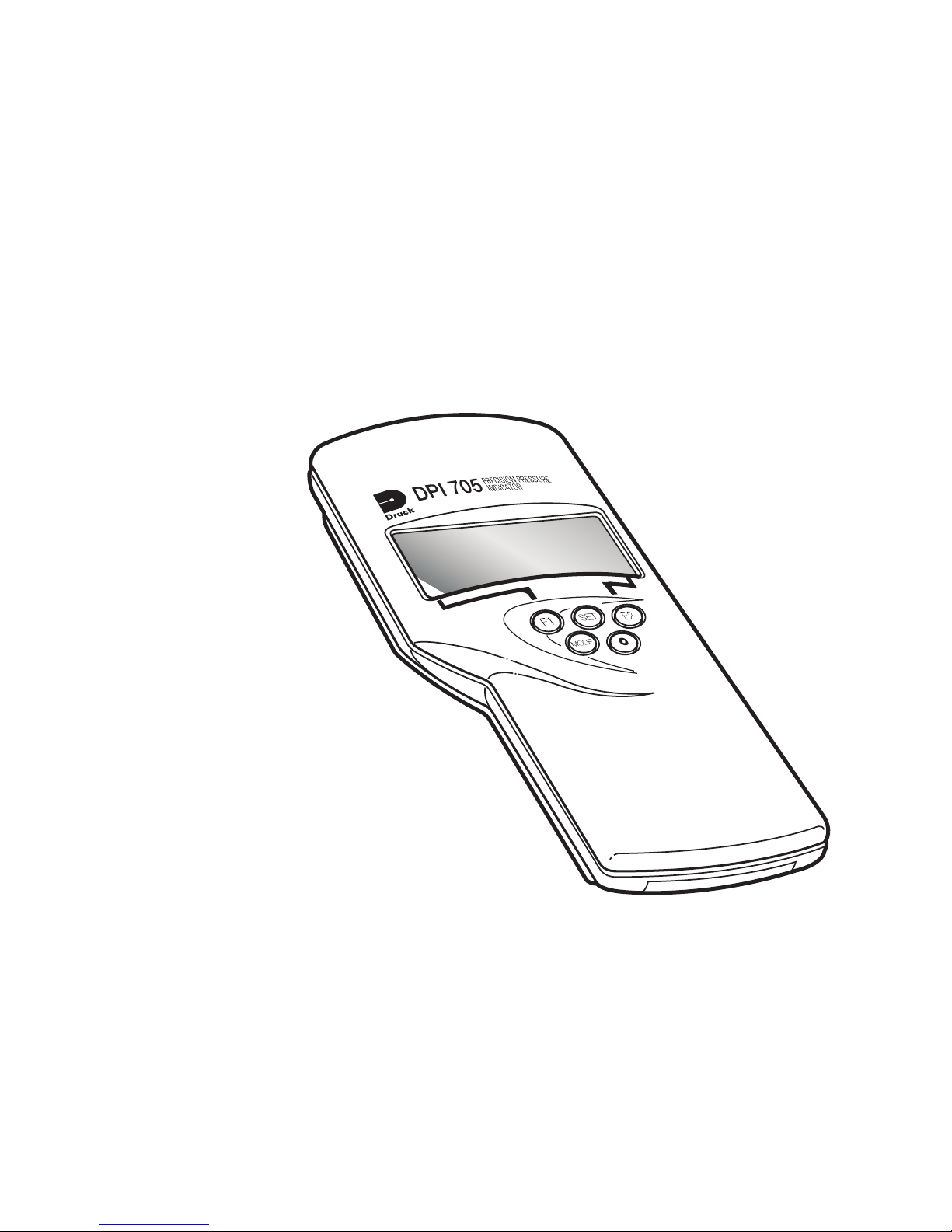
Druck DPI 705/DPI 705 IS Series
Digital Pressure Indicator
User Manual K0214
English 1 - 6
Français 7 - 12
Deutsch 13 - 18
Italiano 19 - 24
Español 25 - 30
Português 31 - 36
GE
Sensing
g
Page 2
©The General Electric Company. All rights reserved
Page 3
Approved Service Agents
For the list of service centres visit our web site:
www.gesensing.com
Symbols
This equipment meets the requirements of all relevant European
safety directives. The equipment carries the CE mark.
This symbol, on the instrument, indicates that the user should
refer to the user manual.
Do not dispose of this product as household waste. Use an
approved organisation that collects and/or recycles waste
electrical and electronic equipment. For more information:
Contact us at www.gesensing.com
Centres de réparation agréés
Pour obtenir la liste des centres de réparation agréés, consultez notre site Web à
l’adresse suivante :
www.gesensing.com
Symboles
Cet appareil satisfait aux exigences de toutes les directives
européennes de sécurité applicables. Cet appareil porte le
marquage CE.
Ce symbole, sur l’instrument, indique que l’utilisateur doit
consulter le manuel d’utilisation.
Ne jetez pas ce produit avec vos ordures ménagères. Faites
appel à un organisme agréé de collecte et/ou de recyclage des
déchets électriques et électroniques. Pour plus d’informations :
Contactez-nous via le site Web www.gesensing.com
Page 4

Autorisierte Servicevertretungen
Eine Liste der Servicezentren finden Sie auf unserer Webseite:
www.gesensing.com
Symbole
Dieses Gerät erfüllt die Anforderungen der entsprechenden
europäischen Sicherheitsrichtlinien. Das Gerät ist mit dem CEPrüfzeichen versehen.
Bei diesem Symbol auf dem Gerät sollte der Anwender im
Handbuch nachschlagen.
Dieses Gerät darf nicht im Haushaltsmüll entsorgt werden.
Geben Sie das Gerät bei einer autorisierten Stelle ab, die alte
Elektro- und Elektronikgeräte sammelt und/oder
wiederverwertet. Weitere Informationen:
Kontaktieren Sie uns unter www.gesensing.com.
Centri di assistenza autorizzati
Per l’elenco dei centri di assistenza consultare il sito:
www.gesensing.com
Simboli
Questa apparecchiatura risponde ai requisiti di sicurezza
imposti da tutte le direttive europee applicabili in materia.
L’apparecchiatura riporta il marchio CE.
Questo simbolo applicato allo strumento suggerisce di
consultare il manuale utente.
Non smaltire il prodotto nei rifiuti domestici. Rivolgersi ad enti
autorizzati alla raccolta e/o al riciclaggio di apparecchiature
elettriche ed elettroniche dismesse. Per ulteriori informazioni
consultare la pagina:
www.gesensing.com
Page 5

Agentes de servicio técnico autorizados
Si desea consultar la lista de centros de servicio técnico, visite nuestro sitio web:
www.gesensing.com
Símbolos
Este equipo cumple los requisitos de todas las directivas
europeas de seguridad pertinentes. El equipo posee la marca
CE.
Este símbolo, en el instrumento, indica que el usuario debe
consultar el manual del usuario.
No deseche este producto como residuo doméstico. Hágalo
mediante una organización autorizada que recoja o recicle
residuos eléctricos y equipos electrónicos. Para obtener más
información:
Póngase en contacto con nosotros en www.gesensing.com
Agentes de manutenção aprovados
Para obter a lista de centros de serviço, visite nosso site:
www.gesensing.com
Símbolos
Este equipamento atende aos requisitos de todas as diretivas
de segurança européias relevantes. O equipamento possui a
marca CE.
Este símbolo, no instrumento, indica que o usuário deve
consultar o manual do usuário.
Não jogue fora este produto como se fosse um resíduo
doméstico. Use uma organização aprovada para coletar e/ou
reciclar equipamentos elétricos e eletrônicos residuais. Para
obter mais informações:
Entre em contato conosco através do site www.gesensing.com
Page 6

intentionally left blank
Page 7
K0214 Issue No. 4
1
Specification
Accuracy:
Combined non-linearity, hysteresis and repeatability .............. ±0.1% full-scale(FS)
Temperature effects: Span ................................................................. ±0.02%rdg/°C
Zero ............... <= 1 bar ±0.05%FS/°C (absolute ranges only)
........................ > 1 bar ±0.02%FS/°C (absolute ranges only)
Maximum safe working pressure .......................................................... 2 x full-scale
Pressure connector ................ 6 mm o/d and 4 mm i/d hose or G1/8 female thread
Environmental .................................................................................................... IP54
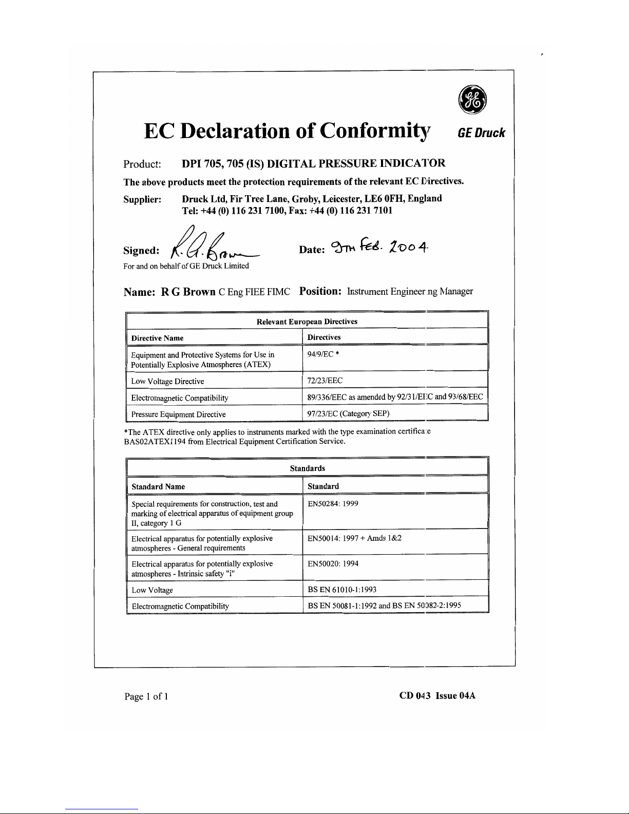
This pressure indicator meets the essential protection
requirements of the relevant EEC directives.
Electrical safety ............................................................ BS EN 61010 as applicable
Electromagnetic compatibility ............................................. EN50081-1 (emissions)
............................................... EN50082-2 (immunity)
Electrical Power Supply for non-certified units ....................... 3 x 1.5 V alkaline size AA
Safety
This symbol, on the pressure indicator, indicates that the
user should refer to the user guide or manual.
Do not apply pressure greater than the maximum safe
working pressure.
Remove batteries from the pressure indicator immediately
when discharged and before storage.
Dispose of batteries in accordance with local regulations and
battery manufacturers' instructions.
When storing and transporting batteries make sure they
cannot be short circuited.
Clean the pressure indicator with a damp cloth.
Refer to the Calibration and Configuration Instructions.
User Manual DPI 705 Series Digital Pressure Indicator
Pressure
Batteries
Cleaning
Calibration
This manual contains operating instructions
for pressure indicators with software version 1.02 onwards. Further
changes to the pressure indicator's software may require a change to the
operating instructions and an issue number change of the manual .
Software Version
Introduction
The Druck DPI 705 pressure indicator uses a micro-machined silicon transducer
to produce a pressure reading in units of pressure measurement. These user
instructions include the operations for all DPI 705 Pressure Indicators, safety
instructions and the requirements for intrinsically safe instruments.
English
Page 8
K0214 Issue No. 4
2
Operation
TIME OUT
If a key is not pressed within 10 minutes then the instrument times out and
switches off. To disable this automatic time out, hold the LEAK key when
switching on the pressure indicator.
LEAK TEST
To perform a leak test, press the LEAK key 3 times. The symbol flashes
on the display with the number 60. To start the leak test press the LEAK key
again. The instrument counts down 60 seconds displaying the leakage at
the end of the 60 second period. Press the LEAK key at any time during the
leak test to quit and return to normal measurement.
ZERO
A zero should be performed on gauge and differential instruments before
measuring pressure. To perform a zero: Open all pressure ports to
atmospheric pressure. Press the and TARE keys together, the display
briefly shows ZErO and the instrument calculates a new zero.
Note: A zero can only be performed on absolute pressure indicators if
a vacuum is first applied to the pressure port.
Alarm
A single alarm can be set to operate when the displayed pressure value rises
above the alarm setting. The alarm causes the display to flash and a beeper
to sound for one minute. Pressing TARE and UNITS keys together displays
the alarm value, pressing the FILTER key increases the alarm value,
pressing the UNITS key decreases the alarm value. When the display
shows the required alarm value, press the TARE key to set the alarm.
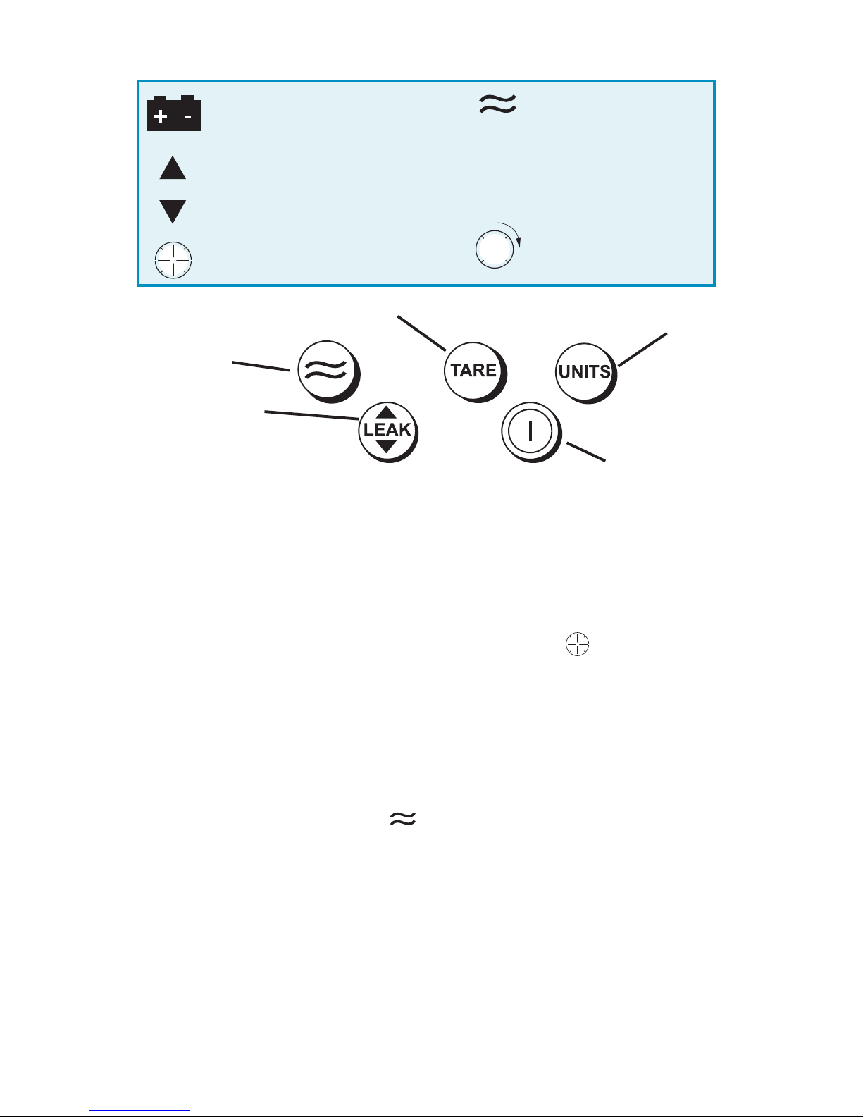
Display Symbols
Switch Tare on or off (changes the
display reading to zero)
Switch filter
on or off
Change units (1 of 16
pressure units, °C or °F)
Switch
on or off
View maximum,
minimum or perform leak
test (max/min is reset at
switch on)
Batteries are low, replace
observing polarity shown on case
Displayed reading - maximum value
Displayed reading - minimum value
TARE
Filter applied
(10 reading rolling average)
Tare applied
Displayed reading - leakage (per
minute)
Leak test in progress
(count down)
A
(flashing)
Alarm - pressure value
more than alarm setting
Page 9

K0214 Issue No. 4
3
English
Intrinsically Safe Pressure Indicators
Introduction
These instructions detail the requirements for using the DPI 705 Intrinsically Safe
Pressure Indicator in a hazardous area. Read the whole publication before
starting.
Installation Requirements in Hazardous Areas
Requirements and Conditions
Batteries
WARNING: ONLY REPLACE BATTERIES IN A SAFE AREA
Only use the battery type listed below.
Installation
Installing should be carried out by qualified plant installation technicians in
compliance with the latest issue of EN 60079-14.
Special Conditions for Use
This pressure indicator may be used in zones 0, 1 and 2 for industries with any
gas group.
Maximum component temperature class T4 (135°C).
Power supply only use 3 x LR6 (AA), Duracell PROCELL, Duracell PLUS,
ENERGIZER ULTIMATE or GP SUPERALKALINE LR6.
Do not apply a pressure greater than 1.1 bar absolute to the negative port of
differential pressure indicators.
Pressure Indicator Casing and Pressure Connector
Avoid impact sparking when installing in a hazardous area.
Provide additional protection for indicators that may be damaged in service.
Marking detail:
DPI 705XX (specific apparatus type)
Pressure range
Serial number/year of manufacture
BAS02ATEX1194 (EC type examination certificate number)
EEx ia IIC T4 (-10°C <=T
amb
<=50°C)
Druck, Groby, UK (manufacturer)
II 1 G
1180
Page 10

K0214 Issue No. 4
4
Declaration Requirements
The DPI 705 is designed and manufactured to meet the essential health and
safety requirements not covered by EC Type Examination Certificate
BAS02ATEX1194 when installed as detailed above.
This intrinsically safe instrument is designed and manufactured to protect
against other hazards as defined in paragraph 1.2.7 of Annex II of the ATEX
Directive 94/9/EC.
Maintenance
Return the instrument to the factory for any repairs, it cannot be repaired on-
site.
To keep the DPI 705 accurate to 0.1% full-scale a calibration check should
be carried out once per year.
Cleaning
Clean the instrument case with a moist, lint-free cloth and weak detergent.
Page 11
K0214 Issue No. 4
5
Preparation
1.
Connect the instrument
to a pressure source
that has an accuracy
three times better than
the instrument.
Recommended:Druck DPI 610 or DPI
610 IS Portable
Calibrator.
2.
Switch on the instrument
and select the units of
pressure measurement
required for calibration.
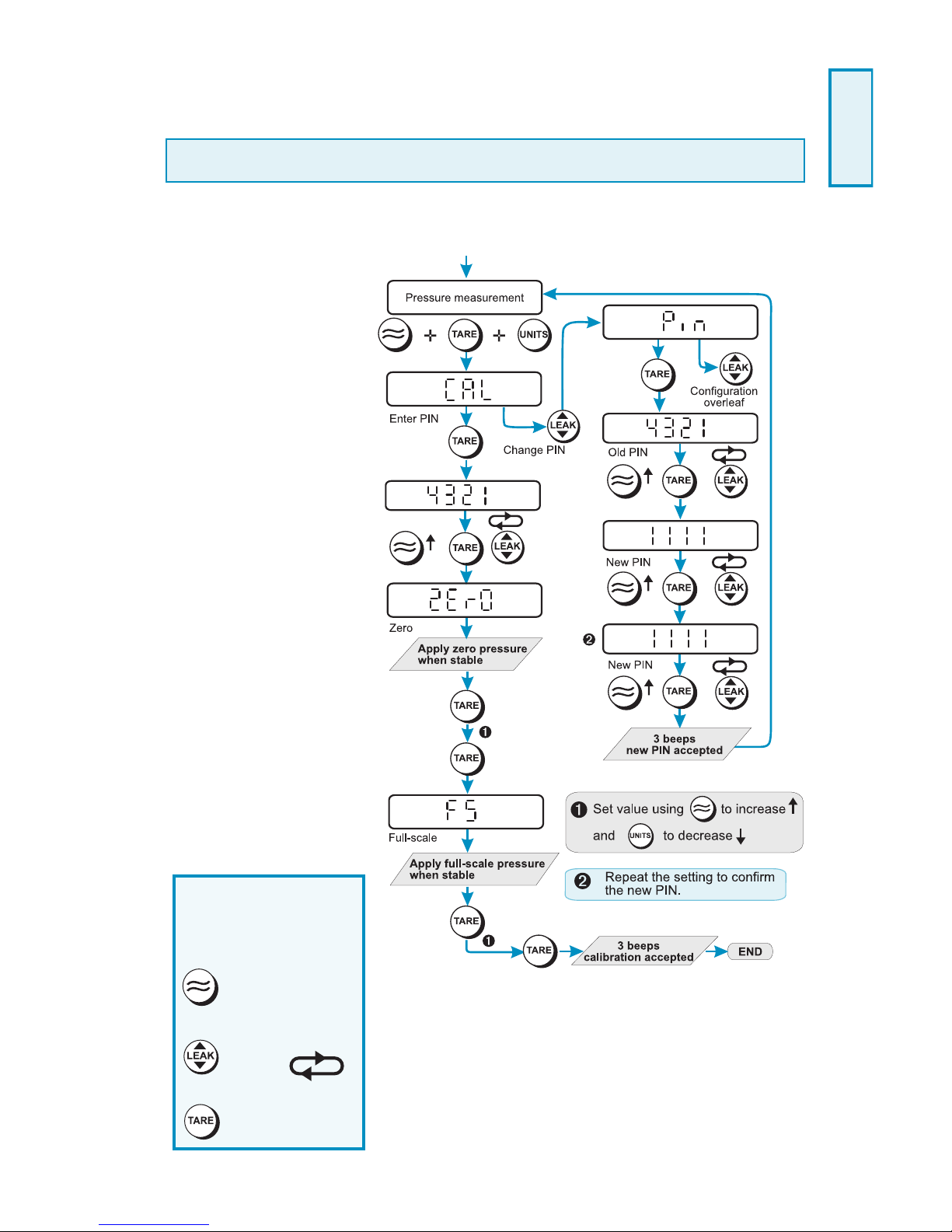
Procedure
1.
Press all three keys
together to enter the
CAL menu and proceed
as shown:
Changing the PIN
Each digit can be
changed in turn.
Pressing:
increases the
value of the digit.
steps to next digit,
left
to right.
enters the PIN
Calibration Instructions
WARNING: CALIBRATE DPI 705 IS INSTRUMENTS IN A SAFE AREA.
The instrument performs a two-point compensation at ZErO and FS (full-scale.)
English
Page 12
K0214 Issue No. 4
6
Page 13
K0214 Issue No. 4
7
Manuel d'utilisation Indicateur de pression serie - DPI 705
Introduction
L’indicateur de pression Druck DPI 705 utilise un capteur silicone micro-usiné
pour produire une mesure de pression en unités de mesure de pression. Cette
notice utilisateur décrit le fonctionnement de tous les indicateurs de pression DPI
705, les consignes de sécurité et les exigences de sécurité intrinsèque des
instruments.
Spécification
Précision :
Non linéarité hystérésis répétabilité .................................... ± 0,1 % Pleine échelle
Effets thermiques: Sensibilité ...................................................... ± 0,02 % lect/° C
Zéro ......................... < = 1 bar ± 0,05 % FS/° C(plages absolues seulement)
..................................... > 1 bar± 0,02 % FS/° C(plages absolues seulement)
Pression de service maximum de sécurité .................................................... 2 x FS
Connecteur de pression ...................................... Flexible de 6 mm Ø ext. et 4 mm
Ø int. ou filet intérieur G 1/8
Environnement .................................................................................................. IP54
Alimentation électrique .......................................... 3 batterie alcalines AA de 1,5 V
Le présent indicateur de pression répond aux exigences des
normes européennes de protection.
Normes de sécurité concernant l'électricité .................... BS EN 61010, s'il y a lieu.
Compatibilité électromagnétique ....................................... EN50081-1 (émissions)
............................................................................... EN50082-2 (insensibilité)
Attention
Quand ce symbole parait sur l'indicateur de pression, se
reporter au Mode d'emploi ou à la Notice d'utilisation.
Ne pas appliquer de pression plus forte que la pression de
service surpression admissible.
Enlever immédiatement les batteries de l’indicateur de
pression dès qu’elles sont déchargées et avant de les
stocker.
Disposer des batteries selon les règlementations régionales
en vigueur et les consignes du fabricant.
Quand vous stockez et transportez les batteries, veillez à ce
qu’elles ne se court-circuitent pas.
Nettoyez l’indicateur de pression à l’aide d’un chiffon
Pression
Batteries
Entretien
Calibration
Version Logiciel Ce manuel renferme les consignes relatives au
fonctionnement et est destiné aux indicateurs de pression dontles logiciels
commencent à partir de la version 1.02. Les changements éventuels apportés au
logiciel de l’indicateur de pression sont susceptibles de modifier les consignes de
fonctionnement de même que le numéro de l’édition de cette notice.
Français
Page 14

K0214 Issue No. 4
8
Fonctionnement
ARRET AUTOMATIQUE
Si vous n’appuyez pas sur une touche dans les 10 minutes, l’instrument s’arrête
automatiquement. Pour invalider cette fonction, maintenez la touche LEAK
enforncée et mettez l’instrument sous tension.
TEST DE FUITE
Pour réaliser ce test, appuyez sur la touche LEAK trois fois. Le symbole
clignote en affichant le chiffre 60. Appuyez de nouveau sur la touche LEAK pour
demarrer le test de fuite. L’instrumente décompte 60 secondes et affiche la fuite à
la fin du compte a rebours. Appuyez sur la touche LEAK à tout moment pendant
le test de fuite pour quitter et revenir au mode standard.
ZERO
Effectuer un zéro sur les instruments relatifs et differentiels avant de procéder à
une mesure. Pour faire le zéro,: ouvrez l’ensemble des orifices de pression à la
pression atmosphérique. Appuyez sur les touches et TARE en même temps,
l’affichage suivant apparait: ZERO et l’instrument calcule le nouveau zéro.
Remarque : Un zéro ne peut s’obtenir sur des indicateurs de pression
absolue qu’à condition d’appliquer le vide sur le port de pression.
Alarme
Il est possible de configurer une alarme qui se déclenche lorsque la valeur de
pression affichée dépasse le consigne. L’alarme fait clignoter l’affichage et un
avertisseur sonore retentit pendant une minute. Si vous appuyez sur les touches
TARE et UNITS en même temps, vous appuyez sur FILTER la valeur d’alarme
augmente, et diminue si vous appuyez sur UNITS. Lorsque l’affichage indique la
valeur souhaitée, appuyez sur la touche TARE pour valider.
Symboles
Tare: ON/OFF
Filtre: ON/OFF
Selection
unités (1 de 16
unités de
pression,
°C ou °F)
Marche/arret
Visualisation maximum,
minimum ou exécute
le test de fuite d’étanchéité
Batteries déchargées, recharger
en respectant la polarité du bac
Affichage - valeur maximum
Affichage - valeur minimum
Affichage - fuite (par minute)
TARE
Filtre
(10 déroulements environ)
A
(clignotante)
Application de la tare
Alarme Valeur de pression
excède la valeur max
Test de fuite
Page 15

K0214 Issue No. 4
9
Notice d’installation
Préparation
Cette notice détaille les exigences d’utilisation de l’indicateur de pression à
sécurité intrinsèque DPI 705 en zone dangereuse. Lire intégralement ce
document avant de commencer.
Indicateurs de pression à sécurité intrinsèque Druck DPI 705
Exigences d’installation dans les zones dangereuses
Détail de marquage :
DPI 705XX (type d’appareil particulier)
Plage de pression
Numéro de série / année de fabrication
BAS02ATEX1194 (numéro de certificat d’examen de type CE)
EEx ia IIC T4 (-10 °C <=T
amb
<=50 °C)
Druck, Groby, UK (fabricant)
Exigences et conditions
Batteries
AVERTISSEMENT : DEPOSER LES BATTERIES DANS UN ENDROIT HORS DE
TOUT DANGER.
Utiliser uniquement le type de batterie indiqué ci-dessous.
Installation
L’installation doit être effectuée sur site par des techniciens qualifiés
conformément à la dernière version de la directive EN 60079-14.
Conditions d’utilisation particulières
Cet indicateur peut être utilisé dans les zones 1 ou 2 d’industries au gaz.
Catégorie de la température maximum des composants : T4 (135º C).
Source d’alimentation …… n’utiliser que 3 batteries LR6 (AA) fabriquées par
Duracell PROCELL, Duracell PLUS, ENERGIZER ULTIMATE ou GP
SUPERALKALINE LR6.
Ne pas appliquer de pression plus forte que la pression absolue de 1,1 bar
sur l’orifice de pression négatif des indicateurs différentiels de pression.
Boîtier d’indicateur de pression et connecteur de pression
Éviter tout jaillissement d’étincelles lors de l’installation dans une zone
dangereuse.
Éviter Assurer une protection supplémentaire des indicateurs risquant d’être
endommagés en cours d’utilisation.
II 1 G
1180
Français
Page 16

K0214 Issue No. 4
10
Déclaration exigée
Le DPI 705 est conçu et réalisé pour satisfaire aux exigences essentielles
d’hygiène et de sécurité non couvertes par le certificat d’examen de type CE
BAS01ATEX1194 lorsqu’il est installé dans les conditions détaillées ci-dessus.
Ce indicateur à sécurité intrinsèque est conçu et réalisé pour assurer une
protection contre les autres dangers définis au paragraphe 1.2.7 de l’Annexe
II de la directive ATEX 94/9/CE.
Entretien
Retourner le indicateur à l’usine pour toute réparation ; il ne peut pas être réparé
sur site.
Pour que DPI 705 demeure précis à 0,1 % de la pleine échelle, un contrôle
d’étalonnage doit être effectué une fois par an.
Nettoyage
Nettoyer le boîtier à l’aide d’un chiffon humide non pelucheux et d’un détergent
doux.
Page 17

K0214 Issue No. 4
11
Préparation
1. Raccordez
l’instrument à une
source de pression
dont la précision est
trois fois meilleure
que celle de
l’instrument.
Recommendation :
Calibreur portable
DPI 610 ou DPI 610
IS de Druck.
2. Mettez l’instrument
sous tension et
sélectionnez les
unités de mesure de
pression souhaitées.
Procédure
1. Appuyez sur les
trois touches en
même temps pour
lancer le menu CAL et
procédez comme suit:
Notices de calibration
AVERTISSEMENT:
CALIBRER LES INSTRUMENTS DPI 705 IS DANS UN LIEU SUR
L’instrument effectue une compensation à deux points en ZERO et PE (pleine échelle).
Changement du Code
PIN
Il est possible de
changer les numéros,
un à la fois en appuyant
sur:
pour incrementer
le numéro
pour obtenir le
numéro suivant,
de gauche
à droite
pour introduire le
Code PIN
Français
Page 18

K0214 Issue No. 4
12
TARE
TARE
Logiciel
Version
Logiciel
Mesures de
pression
Mesures de
pression
Mesures de
pression
LEAK
s
t
LEAK
s
t
A partir du menu d’étalonnage
après avoir appuyé sur
Bloquer
unités
Unités
sélectionnées
Appuyer sur M/A
pour chaque unité
sélectionnée
LEAK
s
t
Introduire PIN
Appuyer sur
M/A
»
TARE
TARE
»
TARE
LEAK
s
t
mbar
3 bips -
programmation
acceptée
»
Introduire PIN
Bloquer unités
M/A
Retour au menu d’étalonnage
au dos de la page
L’indicateur de pression BLOQUE ne mesure que la
température/pression des unités sélectionnées
traiter les données. Les fonctions réservées aux
fuites, alarmes et autres processus ne sont pas disponibles.
sans
TARE
»
TARE
LEAK
s
t
TARE
LEAK
s
t
3 bips -
programmation
acceptée
Consignes de configuration
Page 19

K0214 Issue No. 4
13
Spezifikation
Genauigkeit:
(inkl. Nicht-Linearität, Hysterese-, Widerholbarkeits-Fehler) ......
........................................................................................ ±0,1%v. Maßstab 1:1
Temperatureinfluß: Spanne ................................................. ±0,02% v.Meßwert/°C
Nullpunkt ........................... <= 1 bar ±0,05% v.Endwert/°C (nur Absolutdruck)
............................................. > 1 bar ±0,02% v.Endwert/°C (nur Absolutdruck)
Überlastbarkeit: .................. 2fache Überlastung ohne Einfluß auf die Kalibrierungi
Druckanschluß: ................. Stutzen für 4-/6-mm Schlauch oder G1/8 Innengewinde
Schutzart: ........................................................................................................... IP54
Stromversorgung: .................................................. 3 x 1,5V Alkalibatterie Größe AA
Diese Druckanzeige wird gemäß den einschlägigen ECRichtlinien gefertigt und erfüllt die entsprechenden
Vorschriften.
Elektrischer Schutz ................................................................................... EN 61010
EMV-Emission ........................................................................................ EN 50081-2
EMV-Störfestigkeit ................................................................................. EN 50082-2
Sicherheit
Dieses Symbol auf der Druckanzeige bedeutet, daß der
Benutzer sich auf die Bedienungsanleitung oder das
Handbuch beziehen sollte.
Bringen Sie keinesfalls höheren Druck als den erlaubten
Überdruck auf (2xMeßbereich).
Sofort nach dem Entladen und vor der Lagerung die
Batterien aus der Druckanzeige nehmen.
Die Batterien entsprechend der örtlichen Vorschriften und
den Anweisungen des Batterieherstellers entsorgen.
Stellen Sie sicher, daß die Batterien während Transport und
Lagerung nicht kurzgeschlossen werden können.
Reinigen Sie das Gerät mit einem weichen Tuch, wenden
Sie keinesfalls Lösungsmittel an.
Beziehen Sie sich bezüglich der Kalibrierung auf die
Kalibrations- und Konfigurationsanweisung.
DPI 705 Digitale Druckanzeige Bedienungsanleitung
Einleitung
Die Druck DPI 705-Druckanzeigeeinheit verwendet einen mikrobearbeiteten
Druckgeber aus Silizium zur Ermittlung von Messwerten in Druckmessgeräten.
Diese Benutzeranweisungen enthalten Hinweise zur Bedienung aller DPI 705Druckanzeigeeinheiten, Sicherheitshinweise sowie die Anforderungen für
eigensichere Geräte.
Druck
Batterien
Reinigung
Kalibrierung
Software Version Diese Anleitung enthält Betriebsanweisungen
für Druckanzeigen ab der Softwareversion 1.02. Technische
Änderungen vorbehalten.
Deutsch
Page 20

K0214 Issue No. 4
14
Bedienung
TIME OUT
Wird am Gerät für 10 Minuten keine Taste betätigt, schaltet sich das Gerät
automatisch ab. Um die TIME-OUT Funktion abzuschalten, halten Sie die LEAKTaste beim Einschalten gedrückt.
LEAK TEST
Um einen Lecktest auszuführen drücken Sie die LEAK-Taste dreimal. Das
Symbol blinkt und der Timer zeigt 60. Zum Starten des Tests drücken Sie
nochmals LEAK. Der Timer zählt herunter bis auf 0 Sekunden und zeigt
abschließend die Leckage in der gewählten Einheit. Zum Unterbrechen des
Lecktests drücken Sie die LEAK-Taste und das Gerät kehrt in normalen
Meßmodus zurück.
ZERO
Ein Nullpunkt-Abgleich soll bei Überdruck- und Differenzdruck-Meßgeräten
grundsätzlich vor jeder Messung stattfinden. Dazu alle Druckanschlüsse gegen
Atmosphäre entlüften. Die und die TARE-Taste gleichzeitig drücken, das
Display zeigt kurz ZErO und die Anzeige springt auf Null.
Anmerkung: Bei Geräten in Absolutdruck-Meßbereichen muß vor dem
Nullpunktabgleich eine Vakuumpumpe (Enddruck maximal 0,1 mbar absolut)
an den Druckanschluß gekoppelt werden.
Alarm
Bei Überschreiten des zuvor eingestellten ALARM-Grenzwertes blinkt der
Meßwert im Display und es ertönt ein Warnton. Werden die TARE-und UNITSTasten gleichzeitig gedrückt, wird der aktuelle Grenzwert angezeigt. Mit der
FILTER-Taste wird der Grenzwert erhöht, mit der UNITS-Taste verkleinert. Ist der
Grenzwert korrekt eingestellt, wird er mit der TARE-Taste übernommen.
Symbole im Display
Tara ein-/ausschalten (Display zeigt
aktuellen oder genullten Druck)
Filter ein-/ausschalten
Maßeinheit
unter 16
Einheiten
wählen,
Temp. in ° C
oder ° F
Ein/Aus-Schalter
Maximum/Minimum-Anzeige
oder Lecktest starten
(Max/Min wird bei Einschalten
zurückgesetzt)
Batterien leer, bitte wechseln. Polarität
beachten, s. Markierung im Batteriefach
Maximalwert der aktuellen Messung
Minimalwert der aktuellen Messung
TARE
Tiefpaß-Filter
(Mittelwert über 10 Meßwerte)
Tara-Funktion
Leckagemessung bezogen auf
1 Minute
Lecktest läuft gerade
A
(blinkend)
Alarm Druck überschreitet
eingestellten Grenzwert
Page 21

K0214 Issue No. 4
15
Druck DPI 705 IS eigensichere digitale Druckanzeige
Vorbereitung
In diesen Anweisungen werden ausführlich die Anforderungen für den Einsatz der
eigensicheren DPI 705-Druckanzeigeeinheit in einem Gefahrenbereich
dargestellt. Lesen Sie das Dokument vollständig durch, bevor Sie mit der
Installation beginnen.
Installationsanforderungen in Gefahrenbereichen
Kennzeichnungsdetails:
DPI 705XX (spezifischer Gerätetyp)
Druckbereich
Seriennummer/Herstellungsjahr
BAS02ATEX1194 (Nummer des EG-Typenprüfungszertifikats)
EEx ia IIC T4 (-10°C <=T
amb
<=50°C)
Druck, Groby, UK (Hersteller)
Anforderungen und Einsatzbedingungen
Batterien
WARNUNG: DIE BATTERIEN NUR IN EINEM SICHEREN BEREICH ENTFERNEN.
Verwenden Sie nur den unten angegebenen Batterietyp.
Installationsanweisungen
Die Installation muss von einem qualifizierten Anlagentechniker unter
Einhaltung der Anweisungen der aktuellen Ausgabe von EN 60079-14
durchgeführt werden.
Spezielle Einsatzbedingungen
Diese Druckanzeige kann in Zone 1 und 2 für Industrien mit allen Gasgruppen
eingesetzt werden.
Maximale Komponententemperaturklasse T4 (135oC)
Batterien ..... nur 3 x LR6 (AA) von Duracell PROCELL, Duracell PLUS,
ENERGIZER ULTIMATE oder GP SUPERALKALINE LR6 verwenden.
Negativen (-) Druckanschluß oder Differenzdruckanzeiger nicht mit einem Druck
von mehrals 1,1 bar absolutbeaufschlagen.
Gehäuse der Druckanzeigeeinheit und Druckanschluss
Vermeiden Sie bei der Installation des Geräts in einem Gefahrenbereich
Funkenbildung durch Anstoßen.
Statten Sie Druckanzeige, die während des Einsatzes beschädigt werden
können, mit einem größeren Schutz aus.
II 1 G
1180
Deutsch
Page 22

K0214 Issue No. 4
16
Deklarationsanforderungen
DPI 705 ist so ausgelegt und hergestellt, dass bei einer Installation wie oben
beschrieben die wesentlichen Gesundheits- und Sicherheitsanforderungen
erfüllt werden, die nicht vom EG-Typenprüfungszertifikat BAS01ATEX1194
abgedeckt sind.
Dieser eigensichere Druckanzeige ist so ausgelegt, dass er gegen andere
Gefahren als die im Absatz 1.2.7 von Anhang II der ATEX-Richtlinie 94/9/EG
angegebenen schützt.
Wartung
Sie müssen den Druckindicator zur Reparatur ans Werk zurückschicken, da er
nicht vor Ort repariert werden kann.
Führen Sie einmal pro Jahr eine Kalibrierungsprüfung am DPI 705 durch, um die
Genauigkeit von 0.1% des Endwerts zu gewährleisten.
Reinigung
Reinigen Sie das Druckanzeigehäuse mit einem feuchten, flusenfreien Tuch
und einem schwachen Reinigungsmittel.
Page 23

K0214 Issue No. 4
17
Kalibrieranleitung
WARNUNG: DIE INSTRUMENTE DPI 705 IS IN EINEM SICHEREN BEREICH
KALIBRIEREN
Das Gerät linearisiert den eingesetzten Sensor an 2 Punkten, Nullpunkt (ZErO)
und Endwert (FS).
Vorbereitung
1. Verwenden Sie
als Druck-Standard
nur eine hinreichend
genaue
Druckerzeugung,
mindestens
dreifache
Genauigkeit ist
erforderlich.
Empfohlen:
Tragbares
Kalibriergerät
Druck DPI 610 oder
DPI 610 IS
2. Schalten Sie das
DPI 705 ein und
wählen Sie die
gewünschte
Maßeinheit an.
Kalibrieren
1. Drücken Sie die
drei oberen Tasten
gleichzeitig und
gehen Sie vor wie in
folgendem Schema:
PIN-Nummer ändern
Die PIN-Nr. wird
beginnend am linken
Digit eingestellt:
erhöht den Wert
der gewählten
Ziffer springt
zum nächsten
Digit
von links
nach rechts
quittiert die PIN-Nr.
Deutsch
Page 24

K0214 Issue No. 4
18
Konfigurierungsanleitung
TARE
TARE
Software
Softwareversion
Druckmessung
LEAK
s
t
LEAK
s
t
Im Kalibriermenü nach
Drücken von
Einheiten
verriegeln
Gewählte
Einheiten
Ein/Aus nacheinander
für jede gewählte Einheit
einstellen.
LEAK
s
t
Eingabe PIN
Einstellen
Ein/Aus
»
TARE
TARE
»
TARE
LEAK
s
t
mbar
3 Pieptöne =
Einstellung akzeptiert
»
Eingabe PIN
Einheiten verriegeln
Ein/Aus
Geht zurückzum
umseitigen Kalibriermenü
Der VERRIEGELTE Druckanzeiger misst
nur Druck/Temperatur in den gewählten
Einheiten und verarbeitet Daten.
Die Funktionen Alarm, Lecktest (Leak)
und andere Verarbeitungsfunktionen
stehen nicht zur Verfügung.
kei
ne
TARE
»
TARE
LEAK
s
t
TARE
LEAK
s
t
Druckmessung
Druckmessung
3 Pieptöne =
Einstellung akzeptiert
Page 25

K0214 Issue No. 4
19
Manuale per l’uso indicatore digitale di pressione DPI 705
Introduzione
L’indicatore di pressione Druck DPI 705 si avvale di un trasduttore al silicio
microlavorato che genera valori di lettura in unità di pressione. Queste istruzioni
comprendono il funzionamento degli indicatori di pressione DPI 705, le indicazioni
di sicurezza e i requisiti per gli strumenti a sicurezza intrinseca.
Scheda tecnica
Precisione:
Non linearità, isteresi e ripetibilità abbinate .................................... ±0,1%Scala 1:1
Effetti della temperatura: . Span ......................................................... ±0,02%lett/°C
Zero ........................................... <= 1 bar ±0,05%SN/°C (solo campi assoluti)
.................................................. > 1 bar ±0,02%SN/°C (solo campi assoluti)
Pressione massima d’esercizio entro i limiti di sicurezza ............................... 2 x FS
Raccordo di pressione ..... tubo flessibile d.e. 6 mm, d.i. 4 mm o filetto femmina G 1/8
Grado di Protexione ambientale ........................................................................ IP54
Alimentazione elettrica ........................... 3 batterie di 1,5 V alcaline, dimensioni AA
Questo indicatore di pressione soddisfa i requisiti essenziali di
protezione in conformità alle direttive CEE pertinenti.
Sicurezza elettrica .......................................... BS EN 61010 per quanto applicabile
Compatibilità elettromagnetica ............................................ EN50081-1 (emissioni)
..................................................................................... EN50082-2 (immunità)
Sicurezza
Questo simbolo sull’indicatore di pressione invita l’utente a
consultare la guida o il manuale per l’uso
Non applicare pressioni superiori alla pressione massima
d’esercizio entro i limiti di sicurezza.
Rimuovere le batterie dall’indicatore di pressione quando sono
scariche e prima di conservare l’unità.
Smaltire le batterie in conformità alle norme locali vigenti e alle
istruzioni del produttore delle batterie
In sede di immagazzinaggio e di trasporto delle batterie verificare
che non si possa verificare un cortocircuito.
Pulire l’indicatore della pressione con un panno asciutto.
Consultare le istruzioni sulla taratura e la configurazione.
Pressione
Batterie
Pulizia
Taratura
Versione Software La presente manuale contiene le
istruzioni per il funzionamento degli indicatori di pressione con il
software versione 1.02 e successive. Ulteriori variazioni del
software dello strumento potrebbero richiedere la modifica delle
istruzioni per l’uso e del numero di edixione di questa manuale.
Italiano
Page 26

K0214 Issue No. 4
20
Impiego
TEMPORIZZAZIONE
Se entro 10 minuti non viene premuto un tasto, lo strumento si spegne.
Per disattivare la temporizzazione automatica, tenere premuto il tasto LEAK
[perdita] quando si accende l’indicatore di pressione.
PROVA DI TENUTA
Per eseguire la prova di tenuta, premere 3 volte il tasto LEAK. Il simbolo
lampeggia sul display insieme al numero 60. Per dare inizio alla prova di tenuta
premere di nuovo il tasto LEAK. Lo strumento esegue il conteggio alla rovescia da
60 secondi, ed al termine di questo periodo visualizza la perdita. Per interrompere
la prova di tenuta e ritornare alla normale misura, premere il tasto LEAK in
qualsiasi momento.
AZZERAMENTO
Prima di effetuare una misura di pressione con strumenti relativi o differentenziali
occorre prima eseguire un azzeramento. Per eseguire l'azzeramento aprire tutti i
fori di pressione alla pressione atmosferica. Premere contemporaneamente i tasti
e TARE. Sul display viene visualizzato brevemente ZErO, e lo strumento
calcola il nuovo azzeramento.
N.B. L’azzeramento degli indicatori di pressione assoluta può essere eseguito solo
se viene prima applicata la depressione al l'ingresso di pressione
Allarme
È possibile impostare un allarme che scatta quando la pressione visualizzata
supera il valore di allarme impostato. L’allarme fa lampeggiare il display, e
l’avvisatore acustico suona per un minuto. Per visualizzare il valore dell’allarme
premere contemporaneamente i tasti TARE e UNITS; per aumentare il valore di
allarme premere il tasto FILTER; per ridurre il valore di allarme premere il tasto
UNITS. Quando viene visualizzato il valore di allarme richiesto, premere il tasto
TARE per settare l’allarme.
Simboli visualizzati
Interruttore della Tara (azzera la lettura visualizzata)
Interruttore del filtro
Cambia le
unità (da 1 a
16 unità di
pressione °C
o °F)
Interruttore
Visualizza il valore
massimo ominimo,
o esegue la prova di tenuta
(max/minvengono risettati all’accensione)
Batterie scariche. Sostituirle
osservando la polarità sul contenitore
Lettura visualizzata - valore massimo
Lettura visualizzata - valore minimo
TARE
Filtro applicato
(media 10 letture)
Tara applicata
Lettura visualizzata - perdita (al
minuto)
Prova di tenuta in corso
(conteggio alla rovescia)
A
(lampeggiante)
Allarme - Pressione
superiore al valore di
allarme
Page 27

K0214 Issue No. 4
21
Indicatore di pressione Druck a sicurezza intrinseca serie DPI 705
Preparazione
Queste istruzioni illustrano i requisiti necessari per l’uso dell’indicatore di
pressione a sicurezza intrinseca DPI 705 in un’area pericolosa. Si consiglia di
leggere interamente la pubblicazione prima di iniziare l’installazione.
Requisiti per l’installazione in aree pericolose
Dettaglio della marcatura:
DPI 705XX (tipo di apparecchio specifico)
Campo di pressione
Numero di serie/anno di costruzione
BAS02ATEX1194 (numero del certificato di collaudo CE)
EEx ia IIC T4 (-10°C <=T
amb
<=50°C)
Druck, Groby, UK (costruttore)
Requisiti e condizioni
Batterie
AVVERTENZA: RIMUOVERE LE BATTERIE SOLTANTO IN UN LUOGO
SICURO.
Usare esclusivamente le batterie indicate di seguito.
Installazione
Queste istruzioni descrivono la procedura da eseguire per l’installazione dei
indicatore di pressione della serie DPI 705 che deve essere effettuata da tecnici
qualificati in conformità dell’ultima versione della norma EN 60079-14.
Particolari condizioni d’uso
Questo indicatore di pressione può essere utilizzato nelle zone 1 o 2 per le
industrie con qualsiasi gruppo di gas.
Temperatura componente massima classe T4 (135°C)
Alimentazione ...... usare soltanto 3 batterie LR6 (AA) prodotte da Duracell
PROCELL, Duracell PLUS, ENERGIZER ULTIMATE o GP SUPERALKALINE LR6.
Non applicare una pressione superiore a 1,1 bar assoluta alla porta di pressione
negativa (-ve) degli indicatori della pressione differenziale.
Custodia dell’indicatore di pressione e attacco di pressione
Evita che si generino scintille dovute a urti durante l’installazione in aree
pericolose.
Proteggere maggiormente i trasmettitori che si possono danneggiare
durante l’impiego.
II 1 G
1180
Italiano
Page 28

K0214 Issue No. 4
22
Requisiti della dichiarazione
Il modello DPI 705 è progettato e costruito per soddisfare i requisiti essenziali
in materia di protezione e sicurezza non previsti dal Certificato di collaudo
BAS01ATEX1194 se s’installa nel modo sopra descritto.
Questo indicatore di pressione a sicurezza intrinseca è progettato e costruito
per proteggere dai rischi definiti al paragrafo 1.2.7 dell’Allegato II della
direttiva 94/9/CE.
Manutenzione
Inviare il indicatore di pressione al produttore per le riparazioni poiché non è
riparabile sul posto.
Per mantenere l’accuratezza dei indicatore di pressione DPI 705 allo 0,1% del
fondo scala, si deve eseguire una verifica della calibrazione una volta all’anno.
Pulizia
Pulire il indicatore di pressione con un panno senza sfilacciature inumidito e
un detergente blando.
Page 29

K0214 Issue No. 4
23
Istruzioni per la taratura
AVVERTENZA: CALIBRARE GLI STRUMENTI DPI 705 IS IN UN' AREA SICURA
Lo strumento esegue una compensazione a due punti a ZErO ed FS (Fondo Scala)
Allestimento
1. Collegare lo
strumento ad una
fonte di pressione
avente una
precisione tre volte
superiore a quella
dello strumento.
Si consiglia il
Calibratore portatile
Druck DPI 610
oppure DPI 610 IS
2. Accendere lo
strumento e scegliere
le unità di misura
della pressione per la
taratura.
Procedura
1. Premere
contemporaneamente
tutti e tre i tasti per
accedere al menu
CAL (taratura), e
proseguire come
illustrato:
Cambio del PIN
Cambiare le cifre a
turno. Premendo:
si aumenta il
valore della
cifra
si ottiene la cifra
seguente,
da
sinistra a destra
si inserisce il PIN
Italiano
Page 30

K0214 Issue No. 4
24
TARE
TARE
Software
Versione
software
Misura della
pressione
Misura della
pressione
Misura della
pressione
LEAK
s
t
LEAK
s
t
Dal menu di ‘Taratura’
dopo aver premuto
Blocco
unità
Unità
di misura
Attiva e disattiva
(ON/OFF) le unità
selezionate una dopo
l'altra
LEAK
s
t
Inserire il PIN
Imposta
ON/OFF
»
TARE
TARE
»
TARE
LEAK
s
t
mbar
3 bip
Configurazione
accettata
»
Inserire il PIN
Blocca unità
ON/OFF
Ritorna al menu di
Taratura a tergo
L’indicatore di pressione LOCKED(bloccato)
misura soltanto la pressione/temperatura
nelle unità selezionate e elabora I dati.
Non sono disponibili le funzioni d’allarme,
perdita e d’altro tipo del processo.
non
TARE
»
TARE
LEAK
s
t
TARE
LEAK
s
t
3 bip
Configurazione
accettata
Istruzioni per la configurazoine
Page 31

K0214 Issue No. 4
25
Manual del Usuario de DPI 705
Introducción
El indicador de presión Druck DPI 705 utiliza un transductor de silicio micropulido
para generar una lectura de presión en unidades de medida de presión. Estas
instrucciones para el usuario incluyen las operaciones de todos los indicadores de
presión DPI 705, las instrucciones de seguridad y los requisitos para los
instrumentos intrínsecamente seguros.
Especificación
Precisión:
Error combinado de no linealidad, histéresis y repetitividad
.......................................................................................... ± 0,1 % Escala total
Efectos de Temperatura: Campo .................................................. ± 0,02 % lect/°C
Cero .............................................. < = 1 bar ± 0,05 % FS/°C (Sólo gama absoluta)
................................................. > 1 bar ± 0,02 % FS/°C (Sólo gama absoluta)
Sobre presión máxima de trabajo ................................................................... 2 X FS
Conector de Presión ................ manguito de 6mm d/e y 4mm d/i o rosca hembra G1/8
Ambiente ............................................................................................................ IP54
Acometida Eléctrica .......................................... 3 pilas alcalinas x 1,5V. Tamaño AA
Este indicador de presión cumple con las normativas mínimas de
protección de las directrices correspondientes de la UE.
Seguridad eléctrica ..................................................... BS EN 61010 según proceda
Compatibilidad electromagnética ........................................ EN50081-1 (emisiones)
................................................................................... EN50082-2 (inmunidad)
Seguridad
Este símbolo, en el indicador de presión, indica que el usuario
deberá consultar la guía o manual del usuario.
No poner más presión de la máxima segura de trabajo.
Retirar las pilas del indicador de presión inmediatamente cuando
estén descargadas y antes de guardarlo.
Tirar las pilas según las normativas locales y las instrucciones del
fabricante de las pilas.
Cuando se guarden y se transporten las pilas, comprobar que no
se pueden poner en corto circuito.
Limpiar el indicador de presión con un paño húmedo.
Consultar las Instrucciones de Calibración y Configuración.
Presión
Pilas
Limpieza
Calibración
Español
Versión de Soporte Lógico Esta guía contiene
instrucciones de operación para los indicadores de presión con versión
informática 1.02 y superior. Otros cambios al programa de soporte lógico
del indicador de presión pueden necesitar cambios a las instrucciones de
operación y un cambio de emisión de número en esta guía.
Page 32

K0214 Issue No. 4
26
Operación
TIEMPO LÍMITE
Si no se pulsa ninguna tecla antes de 10 minutos, el instrumento se desconecta.
Para desactivar esta desconexión automática, pulsar y mantener la tecla LEAK al
conectar el indicador de presión.
PRUEBA DE FUGA
Para realizar una prueba de fuga pulsar le tecla LEAK 3 veces. El símbolo
parpadea en la pantalla y presenta el número 60. Para comenzar una prueba de
fuga pulsar la tecla LEAK de nuevo. El instrumento cuenta hasta 60 segundos,
presentando la fuga al final del período de 60 segundos. Pulsar la tecla LEAK en
cualquier momento durante la prueba de fuga para salir y volver a la medida
normal.
CERO
El medidor y los instrumentos diferenciales se deben poner a cero antes de medir
la presión. Para poner a cero: Abrir todas las salidas de presión a la presión
atmosférica. Pulsar las teclas y TARE juntas, en la pantalla aparece
brevemente ZErO y el instrumento calcula un nuevo cero.
Nota: Sólo se puede poner cero en los indicadores de presión absoluta si se
aplica primero vacío a la salida de presión.
Alarma
Se puede ajustar una alarma sencilla para operar cuando el valor de presión
visualizada suba por encima del ajuste de la alarma. La alarma hace que ha
pantalla parpadee y emita un sonido durante un minuto. Al pulsar las teclas
TARE y UNITS juntas aparece el valor de la alarma. Pulsando la tecla FILTER
aumenta el valor de la alarma. Pulsando la tecla UNITS desciende el valor de la
alarma. Cuando en la pantalla aparece el valor necesario de la alarma, pulsar la
tecla TARE para ajustar la alarma.
Símbolos
Conectar o desconectar la tara (cambia
la lectura visualizada a cero)
Conectar/
desconectar el filtro
Cambia
unidades (1 a
6 unidades
de presión,
Cº ó Fº)
Conexión/
desconexión
Vista máxima/mínima o
realiza prueba de fuga (máx/
mín se reajusta al conectar)
Pilas bajas, cambiar
Mantener la polaridad indicada
en el bastidor
Lectura visualizada - valor máximo
Lectura visualizada - valor mínimo
TARE
Filtro aplicado
(10 promedio lectura rodante)
Tara aplicada
Lectura visualizada
- fuga (por minuto)
Prueba de fuga en
proceso (recuento hacia
atrás)
A
(intermitente)
Alarma - valor presión
más que el ajuste de alarma
Page 33

K0214 Issue No. 4
27
Indicador de Presión Digital Intrínsecamente Seguro
DPI 705 IS
Preparación
Estas instrucciones detallan los requisitos de uso del indicador de presión
intrínsecamente seguro DPI 705 en zonas peligrosas. Lea todo el documento
antes de iniciar la instalación.
Requisitos de instalación en zonas peligrosas
Detalle de las marcas:
DPI 705XX (tipo de aparato específico)
Rango de presión
Número de serie/Año de fabricación
BAS02ATEX1194 (número de certificado de inspección de tipo CE)
EEx ia IIC T4 (-10 °C <=T
amb
<=50 °C)
Druck, Groby, RU (fabricante)
Requisitos y condiciones
Pilas
ADVERTENCIA: RETIRAR LAS PILAS SOLO EN UNA ZONA SEGURA.
Utilice exclusivamente el tipo de batería que se indica a continuación.
Instalación
Que deberán ser llevados a cabo por técnicos cualificados especializados en la
instalación de plantas y con arreglo a la última edición de la norma EN 60079-14.
Condiciones especiales de uso
Este indicador de presión se puede usar en zonas 1 ó 2 para industrias con cualquier
grupo de gas.
La clase de temperatura máxima del componente T4 (135°)
Acometida de potencia........... sólo usa 3 pilas LR6 (AA) fabricadas por Duracell
PROCELL, Duracell PLUS, ENERGIZER ULTIMATE o GP SUPERALKALINE LR6.
No aplicar una presión superior a 1,1 bares absolutos al puerto de presión -ve de
los indicadores de presión diferencial.
Caja y conector de presión del indicador de presión
Evite las chispas provocadas por los impactos si la instalación se realiza en
una zona peligrosa.
Utilice medidas de protección adicionales para los indicadors de presión que
puedan sufrir daños durante el uso.
II 1 G
1180
Español
Page 34

K0214 Issue No. 4
28
Requisitos de declaración
Cuando se instala según las instrucciones anteriores, la unidad DPI 705
cumple los requisitos esenciales de higiene y seguridad no cubiertos en el
Certificado de inspección de tipo CE BAS01ATEX1194.
Este transmisor intrínsecamente seguro se ha diseñado y fabricado para
ofrecer protección contra otros riesgos según se define en el párrafo 1.2.7 del
Anexo II de la Directiva 94/9/CE (ATEX).
Mantenimiento
Envíe el indicador de presión a la fábrica para realizar cualquier reparación;
no es posible repararlo en la instalación.
Para mantener la precisión de la unidad DPI 705 al 0,1% sobre el fondo de
escala, es necesario comprobar la calibración una vez al año.
Limpieza
Limpie el cuerpo del indicador de presión con un paño húmedo y sin pelusas
y con un detergente suave.
Page 35

K0214 Issue No. 4
29
Preparación
1. Conectar el
instrumento a una
fuente de presión que
tenga una precisión tres
veces mayor que el
instrumento:
Recomendado:
Calibrador Portátil
Druck DPI 610 e DPI
610IS.
2. Conectar el
instrumento y
seleccionar las
unidades de medida de
presión necesaria para
la calibración.
Procedimiento
1. Pulsar las tres teclas
juntas para entrar en el
menú CAL y proceder
como sigue:
Instrucciones de Calibración
ADVERTÊNCIA: CALIBRE OS INSTRUMENTOS DPI 705 IS EM UMA ÁREA SEGURA
El instrumento realiza una compensación de dos puntos en Cero y FS (fondo de escala)
Para cambiar la CLAVE
Cada dígito se puede
cambiar por turno.
Pulsar:
Aumenta el valor
del dígito
Pasa al próximo
dígito
izquierda
a derecha
introducir la CLAVE
»
UNITS
TARE
LEAK
s
t
»
TARE
TARE
TARE
TARE
TARE
TARE
TARE
Ë
»
UNITS
Ê
»
TARE
Ë
;;
LEAK
s
t
»
TARE
LEAK
s
t
»
TARE
LEAK
s
t
LEAK
s
t
Ê
Ê
Medida de presión
Introducir
la CLAVE
Cero
Cambiar
la CLAVE
Aplicar presión cero
cuando esté estable
Fondo de escala
CLAVE anterior
CLAVE nueva
CLAVE nueva
3 sonidos - nueva
CLAVE aceptada
Aplicar presión del fondo de
escala cuando esté estable
Ajustar el valor usando
para aumentar
y
para reducir
3 sonidos -
calibración aceptada
FIN
Repetir el ajuste para
confirmar la nueva CLAVE
LEAK
s
t
Página opuesta
de configuración
Español
Page 36

K0214 Issue No. 4
30
TARE
TARE
Soporte l gicoó
Versión
de software
Medida de
presión
Medida de
presión
Medida de
presión
LEAK
s
t
LEAK
s
t
En el menú de
calibración después de pulsar
Bloqueo
unidades
Unidades
seleccionadas
Activar o desactivar
una a una cada unidad
seleccionada
LEAK
s
t
Introducir CLAVE
Activar/
desactivar
»
TARE
TARE
»
TARE
LEAK
s
t
mbar
3 sonidos de
ajuste aceptado
3 sonidos de
ajuste aceptado
»
Introducir
CLAVE
Activar/desactivar
bloqueo unidades
Vuelve a la página opuesta
del menú de calibración
Cuando está BLOQUEADO, el indicador de presión
sólo mide la presión y la temperatura en las unidades
seleccionadas y procesa los datos. Las funciones de
alarma, fuga, etc. no están disponibles.
no
TARE
»
TARE
LEAK
s
t
TARE
LEAK
s
t
Instrucciones sobre configuración
Page 37

K0214 Issue No. 4
31
Manual do usuário Indicador de Pressão Digital DPI 705
Introdução
O indicador de pressão Druck DPI 705 usa um transdutor de silício micromecânico
para produzir uma leitura de pressão em unidades de medida de pressão. Essas
instruções para o usuário incluem as operações de todos os indicadores de
pressão DPI 705, instruções de segurança e requisitos para instrumentos
intrinsecamente seguros.
Especificação
Precisão:
Não-linearidade, histerese e repetibilidade combinadas
.................................................................................... +0,1% Escala completa
Efeitos da temperatura: ... Intervalo .................................................. +0,02%rdg/oC
Zero ................................. <= 1 bar +0,05%GE/oC (gamas absolutas apenas)
.......................................... > 1 bar +0,02%GE/oC (gamas absolutas apenas)
Pressão operacional máxima de segurança .................................................. 2 x GE
Ficha de pressão ................ mangueira de 6 mm d/e e 4 mm d/i ou rosca fêmea G 1/8
Ambiental ........................................................................................................... IP54
Alimentação de Energia ........................................ 3 x 1,5 V, alcalinas, tamanho AA
Este indicador de pressão atende aos requisitos essenciais de
proteção das diretrizes relevantes da EEC.
Segurança elétrica ................................................. BS EN61010 conforme aplicável
Compatibilidade eletromagnética ......................................... EN50081-1 (emissões)
............................................. EN50082-2 (imunidade)
Segurança
Este símbolo, no indicador de pressão, indica que o usuário deve
consultar o guia ou o manual do usuário.
Não aplique pressão superior à pressão máxima operacional de
segurança.
Remova as baterias do indicador de pressão logo após terem
descarregado e antes da armazenagem.
Jogue fora as baterias em conformidade com as regulamentações
locais e as instruções dos fabricantes.
Ao armazenar e transportar baterias, certifique-se de que elas não
provoquem curto-circuito.
Limpe o indicador de pressão com um pano húmido.
Consulte as Instruções de Calibração e Configuração
Pressão
Baterias
Limpeza
Calibração
Versão em Software Este guia contém instruções
operacionais para indicadores de pressão com versão de software 1.02
e posteriores. Outras modificações no software do indicador de
pressão podem exigir uma modificação nas instruções operacionais e
uma alteração do número da versão deste manual.
Português
Page 38

K0214 Issue No. 4
32
Operação
TEMPO DE ESPERA
Se uma tecla não for pressionada dentro de um período de 10 minutos, então o
instrumento sai do tempo de espera e desliga. Para anular este tempo de espera
automático, mantenha pressionada a tecla LEAK ao ligar o indicador de pressão.
TESTE DE VAZAMENTO
Para realizar um teste de vazamento, pressione a tecla LEAK 3 vezes. O símbolo
pisca no ecrã com o número 60. Para iniciar o teste de vazamento, pressione
novamente a tecla LEAK. O instrumento executa uma contagem regressiva de 60
segundos exibindo o vazamento ao fim do período de 60 segundos. Pressione a
tecla LEAK a qualquer momento durante o teste de vazamento para sair e
retornar à medição normal.
ZERAR
Um procedimento de zerar pode ser realizado em manómetro ou em instrumentos
de diferenciais antes de medir pressão. Para zerar: abra todas as portas de
pressão para atingir a pressão atmosférica. Pressione as teclas e TARE
simultaneamente. O display exibe brevemente ZErO e o instrumento calcula um
novo zero.
Obs.: Um procedimento de zerar somente pode ser realizado em indicadores de
pressão absoluta se for primeiro aplicado um vácuo na porta de pressão.
Alarme
Um alarme único pode ser configurado para operar quando o valor de pressão exibido
se eleve acima do configurado para o alarme. O alarme faz com que o ecrã pisque
e soe um bip por um minuto. Pressionando as teclas de TARE e UNITS simultaneamente
exibe o valor de alarme, pressionando a tecla de FILTER aumenta o valor de alarme,
pressionando a tecla UNITS diminui o valor de alarme. Quando o display exibe o valor
de alarme requerido, pressione a tecla TARE para configurar o alarme.
Símbolos do Ecrã
Muda Tara para ligada ou desligada [on ou off]
(altera a leitura do display
para zero)
Muda filtro para ligado
ou desligado [on ou off]
Altera unidades
(1 de 16
unidades de
pressão,
o
C ou oF)
Liga ou desliga
[on ou off]
Baterias estão descarregadas;
substitua observando a
polaridade indicada no invólucro
Leitura do ecrã - valor máximo
Leitura do ecrã - valor mínimo
Filtro aplicado
(média de rolagem de 10 leituras)
Tara aplicada
Leitura do ecrã - vazamento
(por minuto)
Teste de vazamento em
andamento (contagem
regressiva)
Alarme - valor de pressão
superior ao configurado para o
alarme
Visualiza máximo, mínimo
ou realiza teste de vazamento
(max./min. é reinicializado com o interruptor em ligado [on])
TARE
A
(piscando)
Page 39

K0214 Issue No. 4
33
Indicador de Pressão Intrínsecamente Seguros
Preparação
Essas instruções detalham os requisitos para utilizar o Indicador de Pressão
Intrinsecamente Seguro DPI 705 em uma área de risco. Leia a publicação na
íntegra antes de iniciar.
Requisitos e condições
Baterias
ADVERTÊNCIA: REMOVA AS BATERIAS SOMENTE EM UMA ÁREA SEGURA.
Use apenas o tipo de pilha indicado abaixo.
Instalação
A instalação deve ser realizada por técnicos qualificados de instalações em
conformidade com a última edição da EN 60079-14.
Condições especiais de uso
Este indicador de pressão pode ser utilizado em zonas 1 ou 2 para instalações
industriais com qualquer grupo de gás.
A classe de temperatura máxima do componente T4 (135°C).
Alimentação elétrica …….. utilize somente 3 x LR6 (AA) fabricadas pela Duracell
PROCELL, Duracell PLUS, ENERGIZER ULTIMATE ou GP SUPERALKALINE LR6.
Não aplique pressão superior a 1,1 bar absoluto à porta de pressão -ve de
indicadores de pressão diferencial.
Gabinete do indicador de pressão e conector de pressão
Ao fazer a instalação em uma área de risco, evite as faíscas provocadas
por impacto.
Proporcione uma proteção adicional aos transmissores que possam ser
danificados durante a utilização normal.
Requisitos de Instalação em Zonas de Risco
Pormenor das marcas:
DPI 705XX (tipo de aparelho específico)
Gama de pressões
Número de série/ano de fabrico
BAS02ATEX1194 (Número do certificado de inspecção CE)
EEx ia IIC T4 (-10°C <=T
amb
<=50°C)
Druck, Groby, Reino Unido (fabricante)
II 1 G
1180
Português
Page 40

K0214 Issue No. 4
34
Declarações Exigidas
O DPI 705 foi projectado e fabricado para satisfazer os requisitos básicos de
higiene e segurança não cobertos pelo certificado de Inspecção da CE
BAS01ATEX1194, quando for instalado tal como se pormenoriza atrás.
Este transmissor intrinsecamente seguro foi projectado e fabricado para
proteger contra outros riscos, conforme definido no parágrafo 1.2.7 do
Apêndice II da Directiva ATEX 94/9/CE .
Manutenção
Envie o transmissor para a fábrica para reparação, pois ele não pode ser
reparado no local.
Para manter o DPI 705 exacto a 0,1 % da escala completa, deve ser
realizada uma verificação da calibragem uma vez por ano.
Limpeza
Limpe a caixa do transmissor com um pano húmido, sem cotão, e um
detergente suave.
Page 41

K0214 Issue No. 4
35
Instruções de Calibração
ADVERTENCIA: LOS INSTRUMENTOS DPI 705 IS SE DEBEN CALIBRAR EN
UNA ZONA SEGURA
O Instrumento executa uma compensação de dois pontos em ZErO e em
GE (Grande Escala)
Preparação
1. Ligue o instrumento
a uma fonte de pressão
que tenha uma precisão
três vezes maior que a
do instrumento.
Recomendado:
Calibrador Portátil
Druck DPI 610 ó DPI
610 IS.
2. Ligue o instrumento
e selecione as
unidades de medição
de pressão requeridas
para calibração.
Procedimento
1. Pressione as três
teclas simultaneamente
para digitar o menu de
CAL e proceda
conforme mostrado:
Alterando a senha
Cada dígito pode ser
alterado um a um.
Pressionando:
aumenta o valor do
dígito
passa para o dígito
seguinte
à esquerda,
à direita
digita a senha
»
UNITS
TARE
LEAK
s
t
»
TARE
TARE
TARE
TARE
TARE
TARE
TARE
Ë
»
UNITS
Ê
»
TARE
Ë
;;
LEAK
s
t
»
TARE
LEAK
s
t
»
TARE
LEAK
s
t
LEAK
s
t
Ê
Ê
Medição de Pressão
Digite Senha
Altere Senha
Zere
Escala real
Senha Antiga
Nova Senha
Nova Senha
Aplique pressão zero
quando estável
Aplique pressão em escala
real quando estável
3 bipes - nova
senha aceita
FIM
3 bipes -
calibração aceita
Repita o valor configurado para
confirmar a nova senha
para diminuir
Configure valor utilizando
para aumentar
e
LEAK
s
t
Configuração
inversa
Português
Page 42

K0214 Issue No. 4
36
TARE
TARE
Software
Versão do
software
Medição de
pressão
Medição de
pressão
Medição de
pressão
LEAK
s
t
LEAK
s
t
A partir do menu de calibração
após pressionar a tecla
Travar
unidades
Unidades
selecionadas
Defina na seqüência
cada unidade como
ligada ou desligada
LEAK
s
t
Introducir la CLAVE
Configuração
Ligado/Desligado
»
TARE
TARE
»
TARE
LEAK
s
t
mbar
Configuração de
3 bipes aceita
»
Introducir
la CLAVE
Travar unidades
Liga/Desliga
Retorna à página oposta
do menu de calibraç oã
O indicador de pressão TRAVADO somente
mede pressão/temperatura nas unidades
selecionadas e não processa dados. Alarme,
vazamento e outras funções de processo não
estão disponíveis.
TARE
»
TARE
LEAK
s
t
TARE
LEAK
s
t
Configuração de
3 bipes aceita
Instruções de Configuração
 Loading...