

Page 1

roduced,
communicated in any way to third parties, nor stored in any data processing system, without the express written authority of
CERTIFICATE RELATED DRAWING
NOT TO BE MODIFIED WITHOUT
T
HE APPROVAL OF THE CERTIFICATION ENGINEER
APPROVED: M T CONCANNON
RTIFICATES: Baseefa10ATEX0010X
CE
Pressure measurement
for research & industry
Druck Limited
Fir Tree Lane
Groby
Leicester LE6 0FH
England
Tel: 0116 231 7100
Baseefa10ATEX0012X
IECEx BAS 10.0002X
IECEx BAS 10.0004X
DPI 620-IS
Advanced Modular Calibrator
User Manual
K0460
Druck Limited 2010
This document is the property of Druck Limited and may not, either in part or whole, be copied or otherwise rep
Druck Limited.
Page 1 of 98 K0460 Issue 1
Page 2

G DOCHERTY
M CONCANNON
Amendment Record
Iss No Date C/N No Originator Typed Workflow
N
1 21/07/10 N/A Robert Lee Robert Lee 149146 New document
Amendments
o.
Approvals
Engineering
Marketing
M SHELTON
Engineering (Certification)
Technical Communications
R LEE
Page 2 of 98 K0460 Issue 1
Page 3

Print Instructions: K0460
•
Finished Size: A5 Portrait (148 x 210 mm)
• Print in colour throughout (covers + text), saddle stitched.
• Cover to 285 gsm, content to 100 gsm.
THIS HARDCOPY IS NOT TO BE USED AS CAMERA COPY.
Page 3 of 98 K0460 Issue 1
Page 4

Page 4 of 98 K0460 Issue 1
Page 5
GE
Measurement & Control Systems
Druck DPI 620-IS
advanced modular calibrator
user manual - K0460
Page 6
Issue 1
Quick reference data
A1.1
DPI 620-IS: Channel 1 (CH1)
Measure (M) / Source (S) / Power (P)
±30 V (M) ±55 mA (M)
0 to 12 V (S) 0 to 24 mA (S)
±2000 mV (M) 8 RTDs (M/S): Pt1000, Pt500, Pt200, Pt100(385),
0 to 2000 mV (S) Pt50, D 100, Ni 100, Ni 120
0 to 4000 Ω (M/S) 12 Thermocouples (M/S): K, J, T, B, R, S, E, N, L, U, C, D
0 to 5 kHz (M/S)
Switch (M)
Pulse counting and
sourcing up to 5k.
A1.2
DPI 620-IS: Channel 2 (CH2)
±30 V (M) 0 to 20 mA (S)
±2000 mV (M) 24 V nominal; maximum: 20 mA
±55 mA (M) Switch (M)
A1.3
DPI 620-IS + MC 620-IS + PM 620-IS
Pressure* (M)
Gauge: 25 mbar to 200 bar (0.36 to 3000 psi).
Absolute: 350 mbar to 1000 bar (5 to 15000 psi).
Note: Maximum pneumatic pressure: 500 bar (7250 psi).
*Caution: To prevent damage to the PM 620-IS module, only use it within the specified
pressure limit on the label.
Copyright © 2010 General Electric Company. All rights reserved.
Trademarks Microsoft and Windows are either registered trademarks or
trademarks of Microsoft Corporation in the United States and/or
other countries.
®
HART
Communications Foundation.
is a registered trademark of the HART
All product names are trademarks of their respect ive
companies.
ii
Page 7

Issue 1
Safety
General warnings
Electrical warnings
Before using the instrument, read and understand all the
related data. This includes: the applicable local safety
procedures, this publication, and the instructions for any
accessories/options/equipment.
WARNING
• It is dangerous to ignore the specified limits for the
instrument or its related accessories. Do not use the
instrument or accessory if it is not in its normal
condition. Use the applicable protection and obey all
safety precautions.
• To prevent electrical shocks or damage to the
instrument, do not connect more than 30V between the
terminals, or between the terminals and the ground
(earth).
• This instrument uses a Ni-MH battery pack. To prevent
an explosion or fire, do not short circuit, do not
disassemble, keep it safe from damage. For operating
conditions, see Table 11-1.
Pressure warnings
• To prevent battery leakage or heat generation, only use
the battery charger and power supply in the
temperature range 0 to 40°C (32 to 104°F). For
operating conditions, see Table 11-1.
• To make sure the display shows the correct data,
disconnect the test leads before setting the power to on
or change to another measure or source function.
When using a pressure option with the DPI 620-IS calibrator,
these warnings are also applicable:
• Some liquid and gas mixtures are dangerous. This
includes mixtures that occur because of contamination.
Make sure that the equipment is safe to use with the
necessary media.
• Pressurized gases and fluids are dangerous. Before
connecting or disconnecting pressure equipment,
safely release all the pressure.
• To prevent a dangerous release of pressure, make sure
that all the related pipes, hoses and equipment have the
correct pressure rating, are safe to use and are
correctly attached.
[EN] English - K0460 Safety iii
Page 8
Issue 1
• It is dangerous to attach an external source of pressure
to a PM 620-IS series pressure station. Use only the
specified mechanisms to set and control the pressure
in the pressure station.
Cautions
Marks and symbols
on the instrument
To prevent damage to the display, do not use sharp
objects on the touch-screen.
To prevent damage to the PM 620-IS module, only use it
within the specified pressure limit on the label.
Before starting an operation or procedure in this publication,
the user must have the necessary skills (if necessary, with
qualifications from an approved training establishment). Follow
good engineering practice at all times.
Complies with European
Union directives
Read the manual USB port: Mini type B
Ground (Earth)
Do not dispose of this product as household waste. Refer to
Chapter 9 (Maintenance procedures).
More marks and symbols are specified in this manual: electrical marks,
display symbols (Chapter 1); pressure related marks and symbols
(Chapter 4).
Warning - refer to the
manual
connector
ON/OFF
iv Safety K0460 - [EN] English
Page 9
Issue 1
DPI 620-IS
MC 620-IS
PM 620-IS
Pressure calibrator
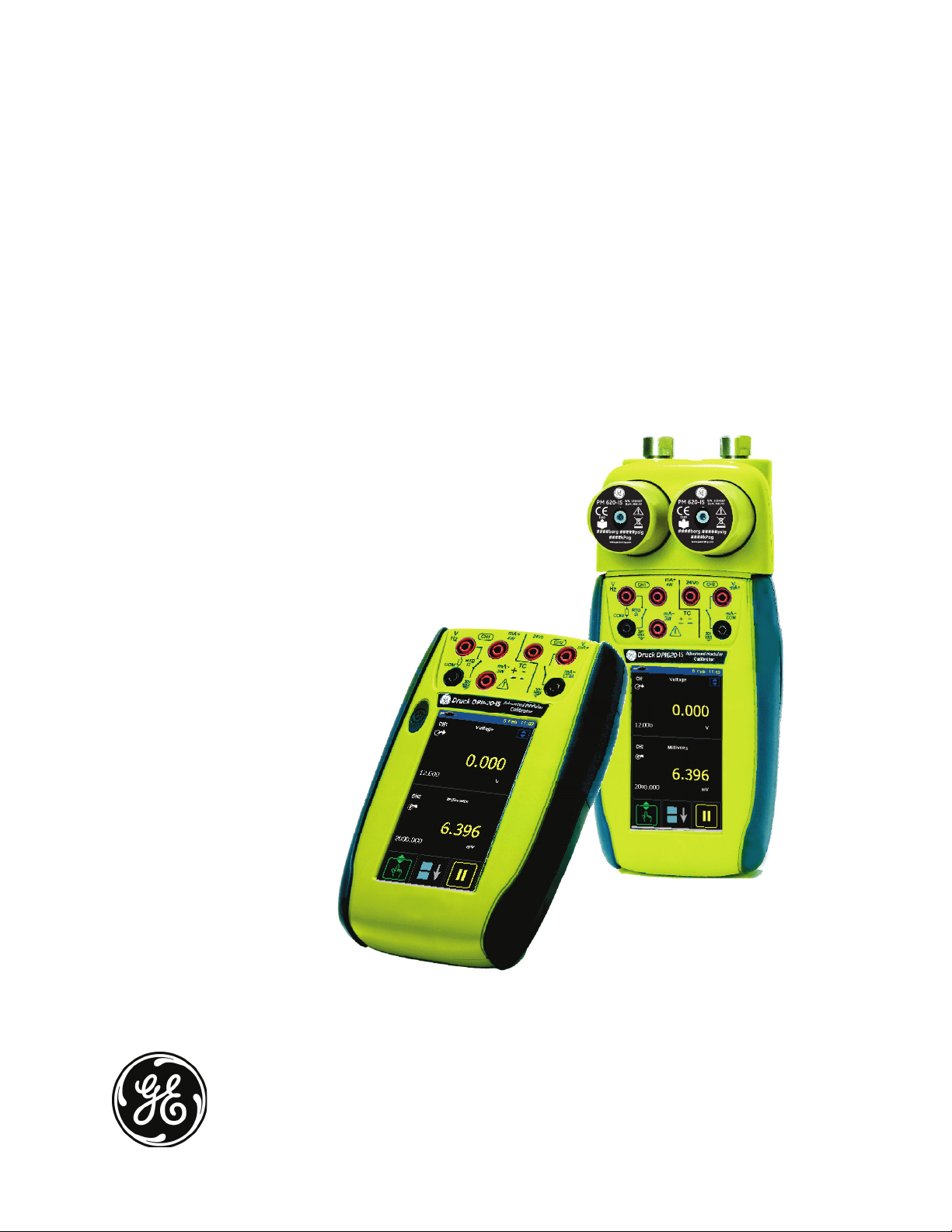
Overview
The intrinsically safe, advanced modular calibrator (AMC) is
part of a set of hand-held modules that can be quickly put
together to include a wide range of calibrator functions.
Advanced modular calibrator, DPI 620-IS (this user
manual): This is a battery-powered instrument for electrical
measure and source operations and HART® communications;
see Table A1 (front cover). It also supplies the power and user
interface functions for all the add-on modules. Use the
touch-screen to display up to six different parameters.
Pressure module carrier, MC 620-IS (this user manual):
This attaches to the DPI 620-IS calibrator to make a fully
integrated pressure indicator instrument. To measure and
display pneumatic or hydraulic pressures, up to two
interchangeable pressure modules can be used at a time.
When not in use fit blanking device (part number 191-369).
Pressure modules, PM 620-IS (this user manual):
Optional item. These modules attach to the pressure module
carrier (MC 620-IS) or to a pressure station (PV 62x-IS) to give
the DPI 620-IS calibrator the necessary pressure measurement
functionality. They are fully interchangeable “plug and play”
modules with no initial set-up or user calibration.
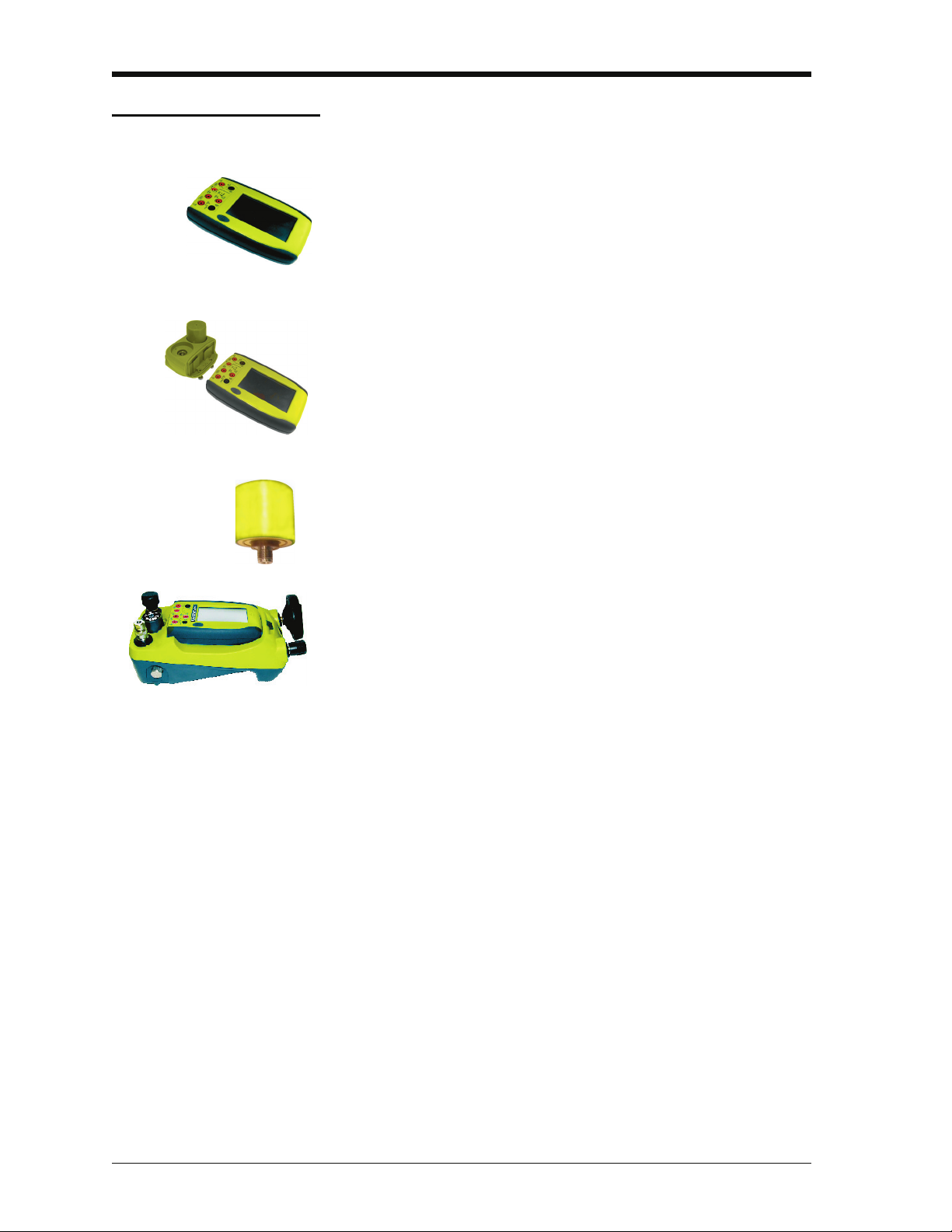
Pressure stations, PV 62x-IS (user manual - K0462:
Optional item. To make a fully integrated pressure calibrator,
attach the DPI 620-IS calibrator to one of the three pressure
stations:
• two pneumatic pressure stations gives an accurate and
controlled pressure and vacuum conditions:
PV 621-IS: -950 mbar to 20 bar (-13.5 to 300 psi) version
PV 622-IS: -950 mbar to 100 bar (-13.5 to 1500 psi) version
• one hydraulic pressure station gives an accurate and
controlled hydraulic pressure conditions:
PV 623-IS: 0 to 1000 bar (15000 psi)
The advanced modular calibrator (AMC-IS) and the pressure
module (PM 620-IS) are part of a set of hand-held modules that
can be quickly put together to include a wide range of calibrator
functions.
To give the attached equipment overpressure protection, there
are pressure relief valves (PRV) available for all the pressure
stations.
[EN] English - K0460 Overview v
Page 10
Issue 1
Software (this user manual): The DPI 620-IS calibrator
includes the following software:
• documenting software • HART® communications software
Other accessories and options: For part numbers (P/N),
refer to Section 1.4 (Accessories).
Summary of
functions
This table gives a summary of the available functions with the
DPI 620-IS calibrator.
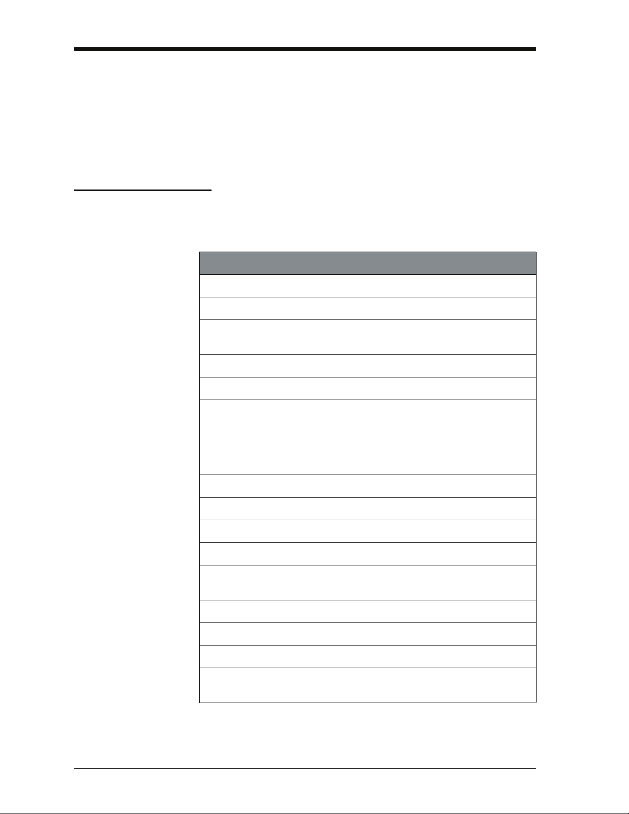
DPI 620-IS - Calibrator functions
Function
Easy to read, Active Matrix Organic Light Emitting Diode Display in colour.
No keys: the touch-screen has large buttons for finger operation.
Rechargeable NiMH battery with enhanced power control for prolonged
battery life.
*
Measure current (mA), voltage (Volts/mV), frequency (Hz/pulse count).
* Supply current (mA), voltage (Volts/mV), frequency (Hz/pulse count).
* Measure/simulate:
- a Resistance Temperature Detector (RTD): Ω or °C/°F
- a thermocouple (TC): mV or °C/°F
- a resistor (Ω)
Cold Junction (CJ) compensation: Automatic/Manual.
Step/Ramp functions: Automatic/Manual.
Switch test and condition indicator (open/closed).
Language selection (see Section 2.8 (Menu sequence)).
Universal Serial Bus (USB) communications ports: For computer
communications, external modules.
®
† Windows
** Measure pressure/Leak test: See pressure accessories.
Documenting software to give an analysis of a device calibration.
Set-up function to save and recall personal settings, instrument calibration
settings and other standard instrument operations.
vi Summary of functions K0460 - [EN] English
CE operating system.
Page 11
* Refer to the datasheet
Example
buttons:
** Optional item
† Factory configured
Issue 1
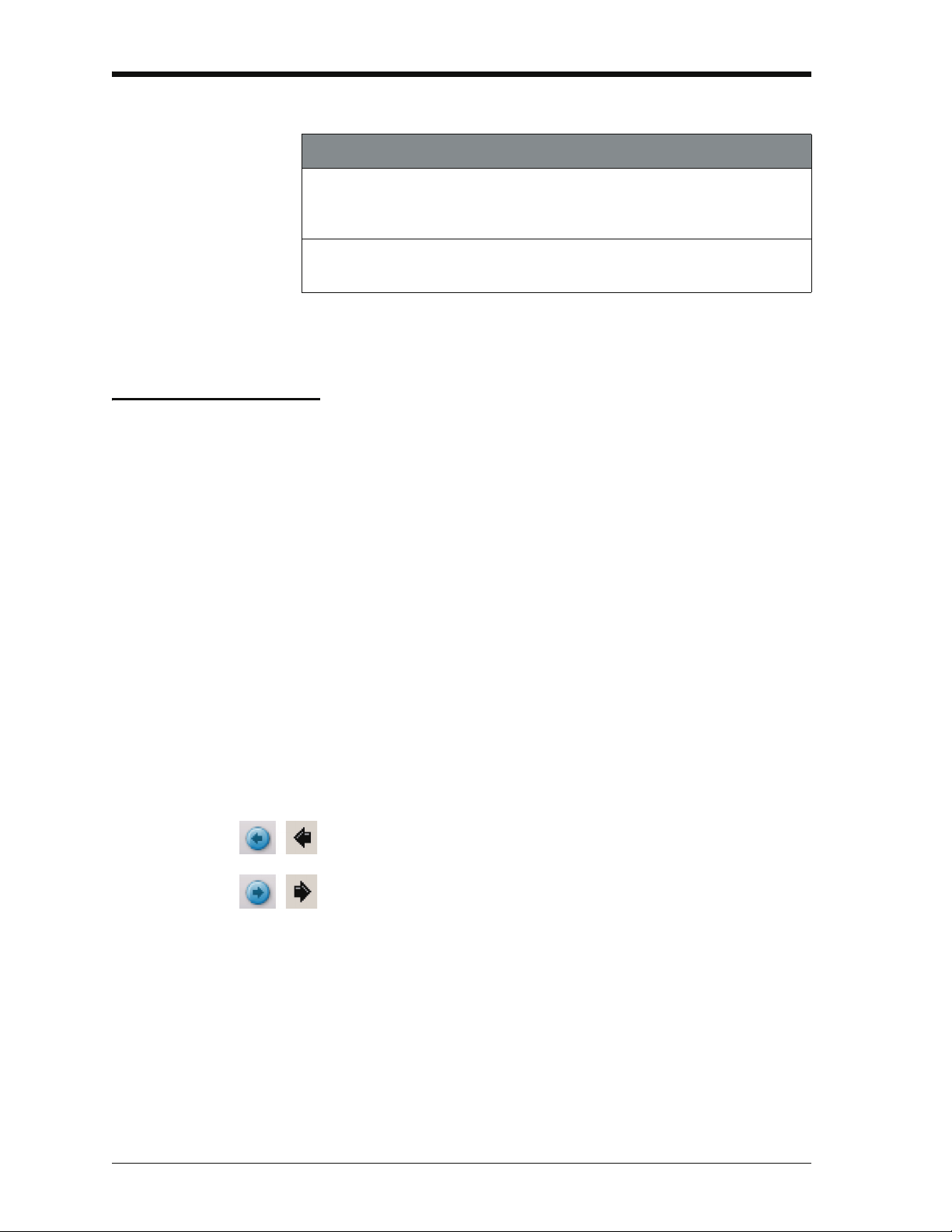
DPI 620-IS - Calibrator functions (Continued)
Function
HART® (Highway Addressable Remote Transducer) communications
software to set up and calibrate devices that use the HART field
communications protocol.
Other functions: Hold, maximum/minimum/average, filter, tare, adjustable
backlight, alarm indication (on the display), automatic power off.
About this manual
This user manual is set up for use on a computer or similar
device that has the necessary software to read a Portable
Document Format (PDF) file.
It is supplied as a PDF on a compact disc (CD) but can be
copied or saved onto a computer or similar device that has the
necessary PDF software.
To navigate between related items of information, the user
manual includes cross references and links (shown in blue); for
example:
• text cross references: ... Figure 1-1; Table 11-1; Chapter 1;
Section 1.4 (Accessories)
Note: Moving the PDF software cursor over an item that has a
link, the cursor symbol normally changes.
Click on a link, and the PDF software shows the applicable
page. To help navigate through the links use, the PDF software
which usually includes these buttons:
Previous view: To go back to a previous page selection.
Next view: In a sequence of page selections, this moves
forward to the next page.
Note: Different software versions have different buttons. In
some versions, it is also necessary to set up the “View” to
include these “Tools” in the “Page Navigation Toolbar”; refer to
the PDF software documentation.
[EN] English - K0460 About this manual vii
Page 12

Issue 1
viii About this manual K0460 - [EN] English
Page 13

Issue 1
Table of Contents
Quick reference data . . . . . . . . . . . . . . . . . . . . . . . . . . . . . . . . . . . . . . . . . . . . . . . . . . . . . . . . ii
Trademarks . . . . . . . . . . . . . . . . . . . . . . . . . . . . . . . . . . . . . . . . . . . . . . . . . . . . . . . . . . . . . . .ii
Safety. . . . . . . . . . . . . . . . . . . . . . . . . . . . . . . . . . . . . . . . . . . . . . . . . . . . . . . . . . . . . . . . . . . iii
Overview . . . . . . . . . . . . . . . . . . . . . . . . . . . . . . . . . . . . . . . . . . . . . . . . . . . . . . . . . . . . . . . . .v
Summary of functions . . . . . . . . . . . . . . . . . . . . . . . . . . . . . . . . . . . . . . . . . . . . . . . . . . . . . . vi
About this manual . . . . . . . . . . . . . . . . . . . . . . . . . . . . . . . . . . . . . . . . . . . . . . . . . . . . . . . . .vii
Table of Contents . . . . . . . . . . . . . . . . . . . . . . . . . . . . . . . . . . . . . . . . . . . . . . . . . . . . . . . . . . ix
Chapter 1: Instrument parts, accessories and options
1.1 Introduction . . . . . . . . . . . . . . . . . . . . . . . . . . . . . . . . . . . . . . . . . . . . . . . . . . . . . . . . 1-1
1.2 The instrument. . . . . . . . . . . . . . . . . . . . . . . . . . . . . . . . . . . . . . . . . . . . . . . . . . . . . . 1-1
1.3 The display . . . . . . . . . . . . . . . . . . . . . . . . . . . . . . . . . . . . . . . . . . . . . . . . . . . . . . . . . 1-3
1.4 Accessories . . . . . . . . . . . . . . . . . . . . . . . . . . . . . . . . . . . . . . . . . . . . . . . . . . . . . . . . 1-4
Chapter 2: Prepare the instrument
2.1 Introduction . . . . . . . . . . . . . . . . . . . . . . . . . . . . . . . . . . . . . . . . . . . . . . . . . . . . . . . . 2-1
2.2 Initial checks . . . . . . . . . . . . . . . . . . . . . . . . . . . . . . . . . . . . . . . . . . . . . . . . . . . . . . . 2-1
2.3 Initial procedures. . . . . . . . . . . . . . . . . . . . . . . . . . . . . . . . . . . . . . . . . . . . . . . . . . . . 2-1
2.4 Power supply . . . . . . . . . . . . . . . . . . . . . . . . . . . . . . . . . . . . . . . . . . . . . . . . . . . . . . . 2-1
2.5 The battery . . . . . . . . . . . . . . . . . . . . . . . . . . . . . . . . . . . . . . . . . . . . . . . . . . . . . . . . . 2-2
2.5.1 Battery condition. . . . . . . . . . . . . . . . . . . . . . . . . . . . . . . . . . . . . . . . . . . . . . . 2-2
2.5.2 Install the battery . . . . . . . . . . . . . . . . . . . . . . . . . . . . . . . . . . . . . . . . . . . . . . 2-2
2.5.3 Charge the battery . . . . . . . . . . . . . . . . . . . . . . . . . . . . . . . . . . . . . . . . . . . . . 2-3
2.5.4 Charge times . . . . . . . . . . . . . . . . . . . . . . . . . . . . . . . . . . . . . . . . . . . . . . . . . 2-3
2.5.5 Operating time . . . . . . . . . . . . . . . . . . . . . . . . . . . . . . . . . . . . . . . . . . . . . . . . 2-4
2.6 Power on or off . . . . . . . . . . . . . . . . . . . . . . . . . . . . . . . . . . . . . . . . . . . . . . . . . . . . . 2-4
2.7 Display operation. . . . . . . . . . . . . . . . . . . . . . . . . . . . . . . . . . . . . . . . . . . . . . . . . . . . 2-4
2.7.1 Change items in a list . . . . . . . . . . . . . . . . . . . . . . . . . . . . . . . . . . . . . . . . . . . 2-5
2.7.2 Change numeric values . . . . . . . . . . . . . . . . . . . . . . . . . . . . . . . . . . . . . . . . . 2-5
2.7.3 Enter text . . . . . . . . . . . . . . . . . . . . . . . . . . . . . . . . . . . . . . . . . . . . . . . . . . . . 2-6
2.7.4 Maximise/minimise a window . . . . . . . . . . . . . . . . . . . . . . . . . . . . . . . . . . . . . 2-6
2.8 Menu sequence . . . . . . . . . . . . . . . . . . . . . . . . . . . . . . . . . . . . . . . . . . . . . . . . . . . . . 2-7
2.8.1 Procedure to set the basic operations: . . . . . . . . . . . . . . . . . . . . . . . . . . . . . . 2-8
2.8.2 Procedure to see the instrument status . . . . . . . . . . . . . . . . . . . . . . . . . . . . . 2-9
2.8.3 Procedures to make Task selections . . . . . . . . . . . . . . . . . . . . . . . . . . . . . . . 2-9
2.8.4 Set a function . . . . . . . . . . . . . . . . . . . . . . . . . . . . . . . . . . . . . . . . . . . . . . . . 2-11
2.8.5 Set the units . . . . . . . . . . . . . . . . . . . . . . . . . . . . . . . . . . . . . . . . . . . . . . . . . 2-12
2.8.6 Set up a utility:Maximum/Minimum/Average example . . . . . . . . . . . . . . . . . 2-12
[EN] English - K0460 Table of Contents ix
Page 14

Issue 1
2.9 Measure and source operations. . . . . . . . . . . . . . . . . . . . . . . . . . . . . . . . . . . . . . . 2-13
2.9.1 Set the Process options (measure) . . . . . . . . . . . . . . . . . . . . . . . . . . . . . . . 2-14
2.9.2 Set the Automation options (source) . . . . . . . . . . . . . . . . . . . . . . . . . . . . . . 2-16
2.9.3 Set the Observed settings (source) . . . . . . . . . . . . . . . . . . . . . . . . . . . . . . . 2-17
2.10 The Advanced menu options . . . . . . . . . . . . . . . . . . . . . . . . . . . . . . . . . . . . . . . . . 2-18
2.10.1 Advanced: Calibration options . . . . . . . . . . . . . . . . . . . . . . . . . . . . . . . . . . . 2-18
2.10.2 Advanced Setup options . . . . . . . . . . . . . . . . . . . . . . . . . . . . . . . . . . . . . . . . 2-19
2.11 The Help menu . . . . . . . . . . . . . . . . . . . . . . . . . . . . . . . . . . . . . . . . . . . . . . . . . . . . . 2-20
Chapter 3: Electrical and IDOS operations
3.1 Introduction . . . . . . . . . . . . . . . . . . . . . . . . . . . . . . . . . . . . . . . . . . . . . . . . . . . . . . . . 3-1
3.2 Measure and source operations. . . . . . . . . . . . . . . . . . . . . . . . . . . . . . . . . . . . . . . . 3-1
3.2.1 Procedure overview . . . . . . . . . . . . . . . . . . . . . . . . . . . . . . . . . . . . . . . . . . . . 3-1
3.2.2 Example procedure: Measure or source current . . . . . . . . . . . . . . . . . . . . . . 3-2
3.2.3 Example procedure: Measure DC voltage . . . . . . . . . . . . . . . . . . . . . . . . . . . 3-3
3.2.4 Example procedure: Source DC voltage (CH1) . . . . . . . . . . . . . . . . . . . . . . . 3-3
3.2.5 Example procedure: Measure or source frequency signals . . . . . . . . . . . . . . 3-4
3.2.6 Example procedure: Measure or simulate an RTD (or Resistance) . . . . . . . . 3-5
3.2.7 Example procedure: Measure or simulate a thermocouple (or TC mV) . . . . . 3-6
3.2.8 Example procedure: Switch test . . . . . . . . . . . . . . . . . . . . . . . . . . . . . . . . . . . 3-8
3.3 Error indications . . . . . . . . . . . . . . . . . . . . . . . . . . . . . . . . . . . . . . . . . . . . . . . . . . . 3-10
Chapter 4: Pressure indicator operation (MC 620-IS)
4.1 Introduction . . . . . . . . . . . . . . . . . . . . . . . . . . . . . . . . . . . . . . . . . . . . . . . . . . . . . . . . 4-1
4.2 Parts and assembly . . . . . . . . . . . . . . . . . . . . . . . . . . . . . . . . . . . . . . . . . . . . . . . . . . 4-1
4.2.1 Assembly instructions . . . . . . . . . . . . . . . . . . . . . . . . . . . . . . . . . . . . . . . . . . . 4-2
4.3 Pressure connections . . . . . . . . . . . . . . . . . . . . . . . . . . . . . . . . . . . . . . . . . . . . . . . . 4-2
4.3.1 Procedure (to attach external equipment) . . . . . . . . . . . . . . . . . . . . . . . . . . . 4-2
4.4 Measure pressure . . . . . . . . . . . . . . . . . . . . . . . . . . . . . . . . . . . . . . . . . . . . . . . . . . . 4-3
4.4.1 Procedure overview . . . . . . . . . . . . . . . . . . . . . . . . . . . . . . . . . . . . . . . . . . . . 4-3
4.4.2 Set-up a Leak Test . . . . . . . . . . . . . . . . . . . . . . . . . . . . . . . . . . . . . . . . . . . . . 4-4
4.4.3 Set the pressure module to zero. . . . . . . . . . . . . . . . . . . . . . . . . . . . . . . . . . . 4-5
4.4.4 Example procedure: Measure pressure . . . . . . . . . . . . . . . . . . . . . . . . . . . . . 4-5
4.5 Error indications . . . . . . . . . . . . . . . . . . . . . . . . . . . . . . . . . . . . . . . . . . . . . . . . . . . . 4-6
Chapter 5: Instrument communications
5.1 Introduction . . . . . . . . . . . . . . . . . . . . . . . . . . . . . . . . . . . . . . . . . . . . . . . . . . . . . . . . 5-1
5.2 Connect to a computer (USB). . . . . . . . . . . . . . . . . . . . . . . . . . . . . . . . . . . . . . . . . . 5-1
x Table of Contents K0460 - [EN] English
Page 15

Issue 1
Chapter 6: Datalog operation
6.1 Introduction . . . . . . . . . . . . . . . . . . . . . . . . . . . . . . . . . . . . . . . . . . . . . . . . . . . . . . . . 6-1
6.2 Set-up . . . . . . . . . . . . . . . . . . . . . . . . . . . . . . . . . . . . . . . . . . . . . . . . . . . . . . . . . . . . . 6-1
6.3 Data Logging . . . . . . . . . . . . . . . . . . . . . . . . . . . . . . . . . . . . . . . . . . . . . . . . . . . . . . . 6-3
6.4 Data handling . . . . . . . . . . . . . . . . . . . . . . . . . . . . . . . . . . . . . . . . . . . . . . . . . . . . . . . 6-3
Chapter 7: Documenting functions
7.1 Introduction . . . . . . . . . . . . . . . . . . . . . . . . . . . . . . . . . . . . . . . . . . . . . . . . . . . . . . . . 7-1
7.2 Analysis . . . . . . . . . . . . . . . . . . . . . . . . . . . . . . . . . . . . . . . . . . . . . . . . . . . . . . . . . . . 7-1
7.3 Run a procedure . . . . . . . . . . . . . . . . . . . . . . . . . . . . . . . . . . . . . . . . . . . . . . . . . . . . 7-2
Chapter 8: HART® device operations
8.1 Introduction . . . . . . . . . . . . . . . . . . . . . . . . . . . . . . . . . . . . . . . . . . . . . . . . . . . . . . . . 8-1
8.2 About HART . . . . . . . . . . . . . . . . . . . . . . . . . . . . . . . . . . . . . . . . . . . . . . . . . . . . . . . . 8-1
8.3 HART Connections . . . . . . . . . . . . . . . . . . . . . . . . . . . . . . . . . . . . . . . . . . . . . . . . . . 8-7
8.3.1 Power supply from the calibrator . . . . . . . . . . . . . . . . . . . . . . . . . . . . . . . . . . 8-7
8.3.2 External loop power . . . . . . . . . . . . . . . . . . . . . . . . . . . . . . . . . . . . . . . . . . . . 8-8
8.3.3 Communicator attached to a network. . . . . . . . . . . . . . . . . . . . . . . . . . . . . . . 8-9
8.3.4 Failed to find device . . . . . . . . . . . . . . . . . . . . . . . . . . . . . . . . . . . . . . . . . . . 8-10
Chapter 9: Maintenance procedures
9.1 Introduction . . . . . . . . . . . . . . . . . . . . . . . . . . . . . . . . . . . . . . . . . . . . . . . . . . . . . . . . 9-1
9.2 Clean the unit . . . . . . . . . . . . . . . . . . . . . . . . . . . . . . . . . . . . . . . . . . . . . . . . . . . . . . . 9-1
9.3 Replace the batteries. . . . . . . . . . . . . . . . . . . . . . . . . . . . . . . . . . . . . . . . . . . . . . . . . 9-1
Chapter 10: Calibration procedures
10.1 Introduction . . . . . . . . . . . . . . . . . . . . . . . . . . . . . . . . . . . . . . . . . . . . . . . . . . . . . . . 10-1
10.2 Before starting . . . . . . . . . . . . . . . . . . . . . . . . . . . . . . . . . . . . . . . . . . . . . . . . . . . . . 10-1
10.3 Selection sequence . . . . . . . . . . . . . . . . . . . . . . . . . . . . . . . . . . . . . . . . . . . . . . . . . 10-2
10.4 Procedures (CH1/CH2): Current (measure). . . . . . . . . . . . . . . . . . . . . . . . . . . . . . 10-3
10.5 Procedures (CH1/CH2): Current (source) . . . . . . . . . . . . . . . . . . . . . . . . . . . . . . . 10-3
10.6 Procedures (CH1/CH2): DC mV/Volts (measure). . . . . . . . . . . . . . . . . . . . . . . . . . 10-5
10.7 Procedures (CH1 mV (measure)/Volts (source) . . . . . . . . . . . . . . . . . . . . . . . . . . 10-6
10.8 Procedures (CH1): Frequency (measure/source) . . . . . . . . . . . . . . . . . . . . . . . . . 10-7
10.9 Procedures (CH1): Frequency amplitude (source). . . . . . . . . . . . . . . . . . . . . . . . 10-9
10.10 Procedures (CH1): Resistance (measure) . . . . . . . . . . . . . . . . . . . . . . . . . . . . . 10-10
10.11 Procedures (CH1): Resistance (source) . . . . . . . . . . . . . . . . . . . . . . . . . . . . . . 10-11
10.12 Procedures (CH1): TC mV (measure or source) . . . . . . . . . . . . . . . . . . . . . . . . 10-12
10.13 Procedures (CH1): CJ (measure) . . . . . . . . . . . . . . . . . . . . . . . . . . . . . . . . . . . . 10-13
10.14 Procedures (CH1): Pressure indicator modules (PM 620-IS). . . . . . . . . . . . . . 10-14
[EN] English - K0460 Table of Contents xi
Page 16

Issue 1
Chapter 11: General specification
11.1 Introduction . . . . . . . . . . . . . . . . . . . . . . . . . . . . . . . . . . . . . . . . . . . . . . . . . . . . . . . 11-1
Customer service. . . . . . . . . . . . . . . . . . . . . . . . . . . . . . . . . . . . . . . . . . . . . . . . . . . . . Back cover
xii Table of Contents K0460 - [EN] English
Page 17
Chapter 1: Instrument parts,
1
2
4
Figure 1-1: General view of
the instrument
3
Figure 1-2: CH1/CH2
connections
2 b ca
accessories and options
1.1 Introduction
1.2 The instrument
This chapter gives a description of the different parts of the
instrument and the accessories/options available.
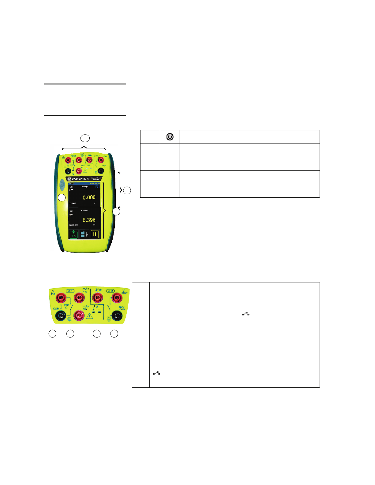
1. On or off button. Refer to “Quick Reference”.
2. CH1 Connectors for Channel 1
CH2 Connectors channel 2
3. USB Connector.
4. Display screen.
2a Channel 1 (CH1) connectors for:
V: volts/mV DC; Hz: frequency and counts/min, counts/hour
(cpm/cph);
resistance temperature detectors; : switch operation; mA+,
mA-: current. Refer to Chapter 3 (Electrical operations).
2b Channel 1 (CH1) connectors for thermocouples (TC). Refer to
[EN] English - K0460 Instrument parts, accessories and options 1-1
Chapter 3.
2c Isolated channel 2 (CH2) connectors for:
V: volts/mV DC; mA+, mA-: current; 24Vo: 24V loop power supply;
refer to Chapter 8.
Ω: resistance; RTD: 2-wire, 3-wire (3W), 4-wire (4W)
: switch operation; refer to Chapter 3. For HART connections,
Page 18
Issue 1
Figure 1-3:
The USB connector
3
5
Figure 1-4: Bottom view
(cover attached)
8
7
6
9
6
Figure 1-5: Bottom view
(cover/battery removed)
11
10
10
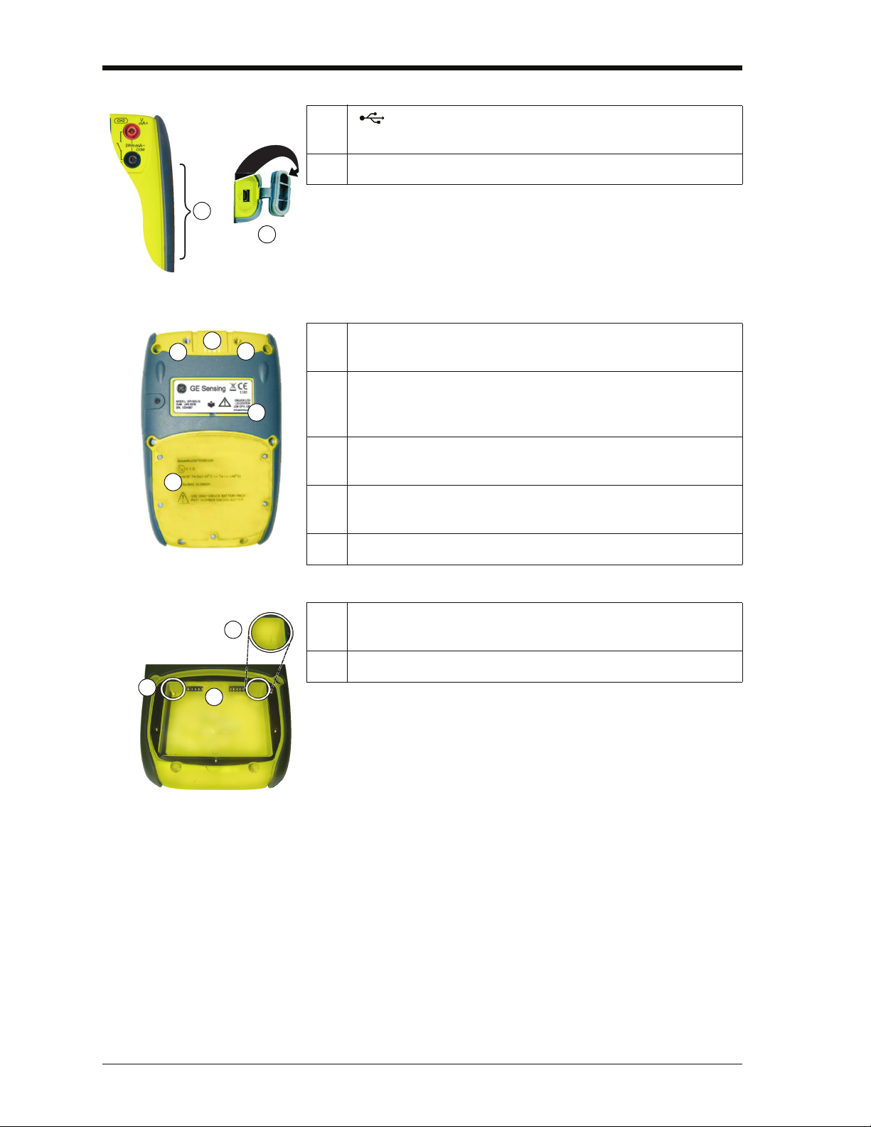
3. : USB mini Type B connector for communication with a
computer.
5. Cover for the USB connector (Figure 1-3). For IP65, press it fully
into the recess over the connectors.
6. Two connection points to attach the pressure module carrier
(MC 620-IS); refer to Chapter 4 (Pressure indicator operation
(MC 620-IS)).
7. Electrical connections for the pressure module carrier
(MC 620-IS) or a pressure station (PV 62x-IS).
8. Label: model, date of manufacture (DoM: month/year), serial
number (S/N); manufacturer: name, address, website
9. Compartment cover for the battery.
10. Two position guides for the battery. Refer to Section 2.5.2 (Install
the battery).
11. Electrical connections for the battery.
1-2 Instrument parts, accessories and options K0460 - [EN] English
Page 19
Issue 1
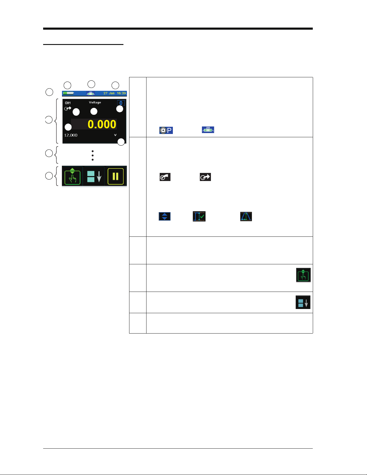
Figure 1-6: Example display
h
b
1
2
4
3
g
a
d
c
e
f
1.3 The display
This is a OLED with a colour display with a touch-screen. To
make a selection, lightly tap on the applicable display area with
a finger; see Section 2.7 (Display operation).
1. Status bar: This includes:
a. Battery indicator b. Date and time
c. Indicators for a Pressure connection, a HART protocol
resistor, Datalog and wireless operation; for example:
: Pressure; : HART
2. CH1: Window for the channel 1 settings and values; see
Section 2.8.1.
d. Measure or source indication:
: Measure; : Source
e. Function (voltage, current, pressure ...)
f. Source process indicator; for example:
: Nudge; : Span check; : Ramp
g. Full scale (FS) range h. Function units
3. Other windows: The number of windows seen on the display is
set by the number of task selections and external modules you
are working with (maximum: 6); see Section 2.7.
4. Tap this button to set up the Task, set up the instrument
(Configure) and to access Help (?). see Section 2.8 (Menu
sequence).
5. Tap this button to maximise each of the available
windows in sequence; see Section 2.7.4
6. Pause (II) or Play (X): Tap (II) to hold (freeze) all the data on the
display. To release the display and continue, tap (X).
[EN] English - K0460 Instrument parts, accessories and options 1-3
Page 20
Issue 1
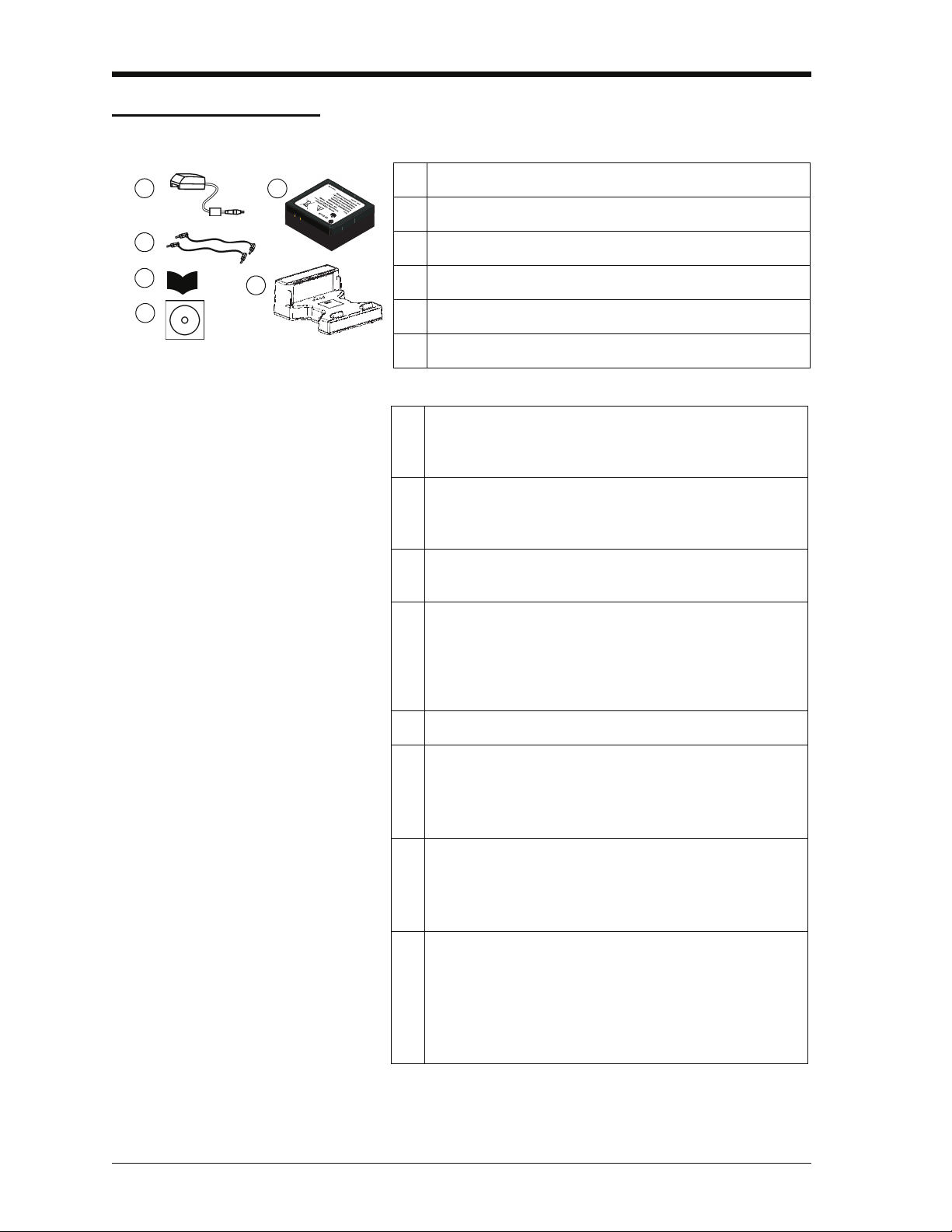
Figure 1-7: Accessories included
1
4
5
2
3
6
1. IO620IS-CHARGER
2. IO620-IS BATTERY. Ni-MH battery
3. 209-539. Set of six electrical test leads
4. K0461. Safety and quick reference guide
5. UD-0004. CD with the user manual
6. IO620IS CRADLE
7. IO620-CASE-1. Fabric carry case with a belt loop,
shoulder strap and a large pocket for accessories. It can
hold one DPI 620-IS calibrator.
8. IO620-CASE-2. Fabric carry case. It can hold a set of
units: one DPI 620-IS calibrator; one MC 620-IS module
carrier; PM 620-IS modules and related accessories.
9. IO620-USB-PC. USB mini Type B cable to connect the
DPI 620-IS calibrator to a computer.
10. IO620-FIELD-CAL. Intecal field calibration manager. Use
the documenting functions in the calibrator with
elements of the Intecal database; set-up new device
records and procedures; upload Intecal data to your
computer database.
11. Pressure modules (PM 620-IS); refer to the datasheet .
12. Pneumatic hose kit rated to 400 bar (5800 psi) with “Quick
fit” connectors for the test port .
IO620-HOSE-P1-IS: 1 metre (≈ 39”)
IO620-HOSE-P2-IS: 2 metre (≈ 78”)
13. Hydraulic hose kit rated to 1000 bar (15000 psi) with
“Quick fit” connectors for the test port .
IO620-HOSE-H1-IS: 1 metre (≈ 39”)
IO620-HOSE-H2-IS: 2 metre (≈ 78”)
14. Pressure adaptor sets designed for the MC 620-IS,
PV 62x-IS and the hose kits:
IO620-BSP: G1/8, G1/4 male; G1/4, G3/8 and G½ female
IO620-NPT: 1/8NPT, ¼NPT male, ¼NPT, 3/8NPT, and
½NPT female
IO620-MET: M14 x 1.5 and M20 x 1.5 female
1.4 Accessories
1-4 Instrument parts, accessories and options K0460 - [EN] English
Page 21

Issue 1
[EN] English - K0460 Instrument parts, accessories and options 1-5
Page 22

Issue 1
1-6 Instrument parts, accessories and options K0460 - [EN] English
Page 23

Chapter 2: Prepare the instrument
2.1 Introduction
2.2 Initial checks
This chapter gives a description of these items:
• the initial checks and procedures
• the available power options
• the battery and related procedures (install and charge)
• the start-up procedures
• the menu structure and options
• the Process and Automation options available for the
measure and source ( )functions
Before using the instrument for the first time:
• Make sure that there is no damage to the instrument, and
that there are no parts missing; see Figure 1-7.
• Remove the plastic film that protects the display. Use the
tag (◗ ) in the top right-hand corner.
2.3 Initial procedures
2.4 Power supply
Before using the instrument for the first time, complete these
procedures:
• Charge the battery (Section 2.5.3).
• Install the fully-charged battery (Section 2.5.2). Then refit
the cover.
• To make sure that the calibration schedule works correctly,
set the date and time; see Section 2.8 (Menu sequence).
This instrument is battery powered:
Ni-MH battery (Section 2.5): All the instrument functions are
available with a fully-charged battery.
[EN] English - K0460 Prepare the instrument 2-1
Page 24
Issue 1
b
2
a
1
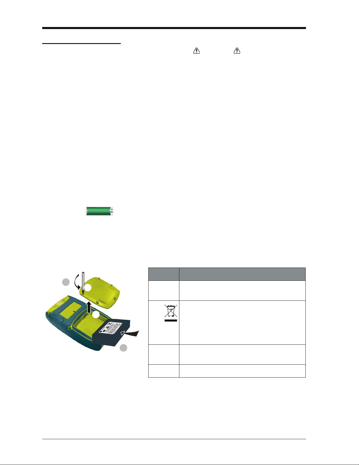
Step Procedure
1. When the power is off, loosen the five screws (a)
and remove the cover (b).
If necessary, turn the instrument over and collect
the discharged battery.
If the battery does not hold a charge, discard it
safely. Obey all the local health and safety
procedures.
2. Install the new fully-charged battery in the
compartment .
3. Refit the cover.
2.5 The battery
2.5.1 Battery condition
Charge indications After switching on, the battery symbol at the top of the display
WARNING
• This instrument uses the GE specified, Ni-MH battery
pack. To prevent an explosion or fire, do not short
circuit, do not disassemble, keep it safe from damage.
For operating conditions, see Table 11-1.
• Charge the GE specified battery in a safe area, using the
GE supplied charger and cradle.
• To prevent battery leakage or heat generation, only use
the battery charger and cradle in the temperature range
0 to 40°C (32 to 104°F). For operating conditions, see
Table 11-1.
For a full battery specification, refer to Table 11-1.
On receipt of a new DPI 620-IS calibrator, the battery will be
partly-charged. We recommend that it is fully-charged
(Section 2.5.3).
shows the charge condition in 10% increments.
To get an accurate indication (1% increments), use the
Configuration menu; see Section 2.8.2 (Procedure to see the
instrument status).
2.5.2 Install the battery
2-2 Prepare the instrument K0460 - [EN] English
Page 25
Issue 1
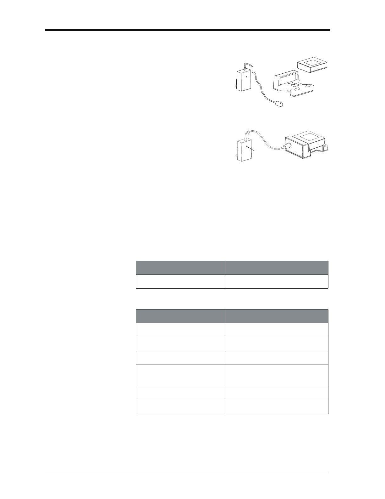
[a]
[b]
[c]
[d]
2.5.3 Charge the battery
Fully-charge the battery, using
the charger and cradle, in a
safe area.
• The battery pack [a] (part
number: IO620IS – Battery)
will be partly-charged, it is
recommended to fully
charge the battery pack
before using the instrument:
• Connect the charger [b]
(part number:
IO620IS-Charger) to a
power supply.
• Connect the charger to the cradle [c] (part number:
IO620IS-Cradle).
• Correctly insert the battery into the cradle (making sure the
battery pack label faces upwards).
• The battery charger LED [d] indicates the different charge
states. When the LED shows green the battery pack is
fully-charged and ready to use. The battery pack takes
approximately 8 hours to fully charge.
2.5.4 Charge times
Charge method Charge time (to full capacity)
External battery charger
≈ 6.5 hours
During the charge cycle the charger LED indicator changes
colour:
LED Indicator Mode
Yellow Battery not connected
Yellow Battery initialisation and analysis
Orange Fast charge
Green with intermittent yellow
flash
Green Trickle charge
Alternating orange - green Error
Top-off charge
[EN] English - K0460 Prepare the instrument 2-3
Page 26
Issue 1
TAP
2.5.5 Operating time
Operation Battery duration
Continuous operation (measure) > 10 hours
Continuous operation (measure and
source with loop power on)
These are typical operating times for a new, fully-charged
Ni-MH battery pack with these settings:
> 6 hours
• Backlight Intensity set to 80% (Default: 80%).
• Backlight Timeout set to 2 hours (Default: 2 minutes).
Power save options To get the best battery duration, set a low value for the
Backlight Intensity (40%) and a short Timeout; see
Section 2.8.1 (Procedure to set the basic operations:).
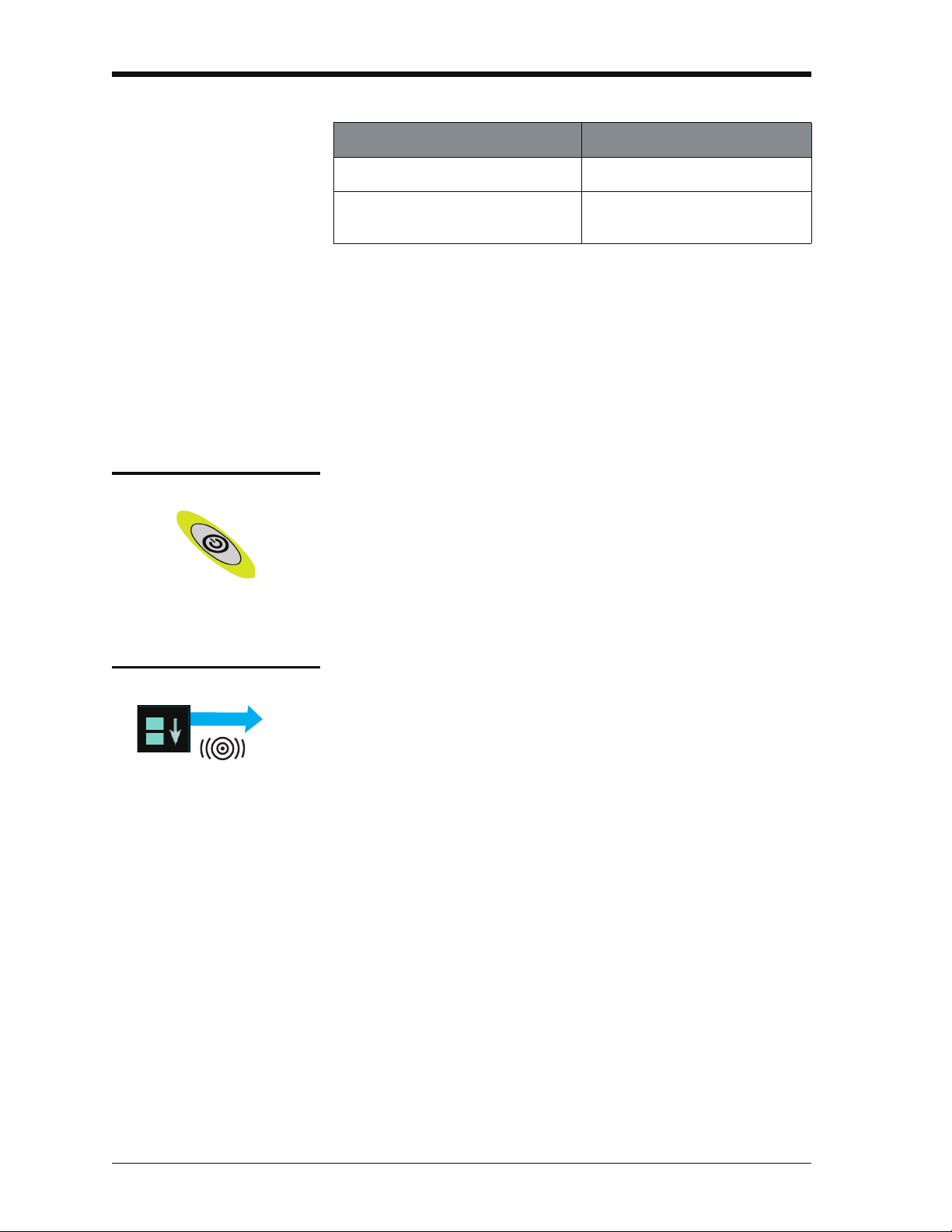
2.6 Power on or off
To set the instrument power on, press and hold this button
down until the display comes on (≈ 2 seconds). During the
power on sequence, the instrument shows a timer and then
shows the applicable data.
To set the instrument power off, press and hold this button.
When the power is off, the last set of configuration options
stays in memory.
2.7 Display operation
This instrument has a touch-screen. To make a selection,
lightly tap on the applicable display area (window, button,
option) with a finger.
Caution: To prevent damage to the display, do not use
sharp objects on the touch-screen.
The number of windows shown on the display is set by the
number of task selections and external modules enabled
(maximum: 6); see Section 2.8.3 (Procedures to make Task
selections).
2-4 Prepare the instrument K0460 - [EN] English
Page 27
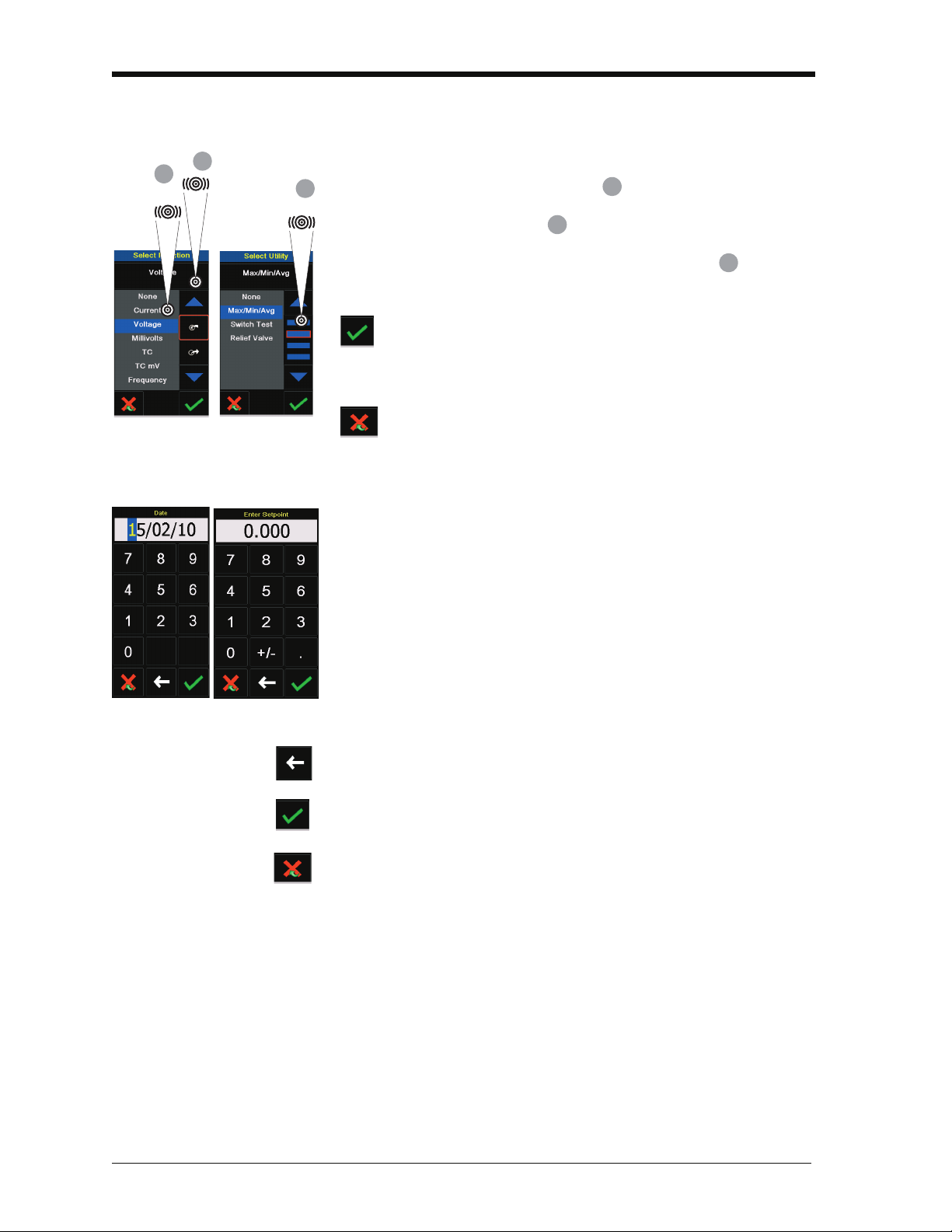
2.7.1 Change items in a list
A
B
C
ABC
2.7.2 Change numeric values
Issue 1
To change an item in a list, you have these options:
• tap on the item you want to use .
• tap on the ▲ or ▼ button .
• tap on one of the horizontal bars beside the list
(if applicable).
Accept: To accept the selection and go back to the
previous display, tap this button. If necessary, tap this
button on all subsequent displays until you get back to
the start.
Cancel: To cancel the selection and go back to the
previous display, tap this button
There are numeric key-pad displays for these items:
• dates and times
• set-point values
• source Automation processes (Nudge, Span Check, ... )
• calibration and other processes
Tap in the necessary value on the key-pad. If applicable, the
key-pad includes the buttons for +/- and decimal point.
Backspace: To go back one character, tap this button. If it is
not a date or time, it deletes the character.
Accept: To accept the specified value and go back to the
previous display, tap this button.
Cancel: To cancel the specified value and go back to the
previous display, tap this button.
[EN] English - K0460 Prepare the instrument 2-5
Page 28
Issue 1
1
2
TAP
Maximise Minimise
*
*
* Alternative options for step ➀
2
1
1
Processes (measure operations )
Automation (source operations )
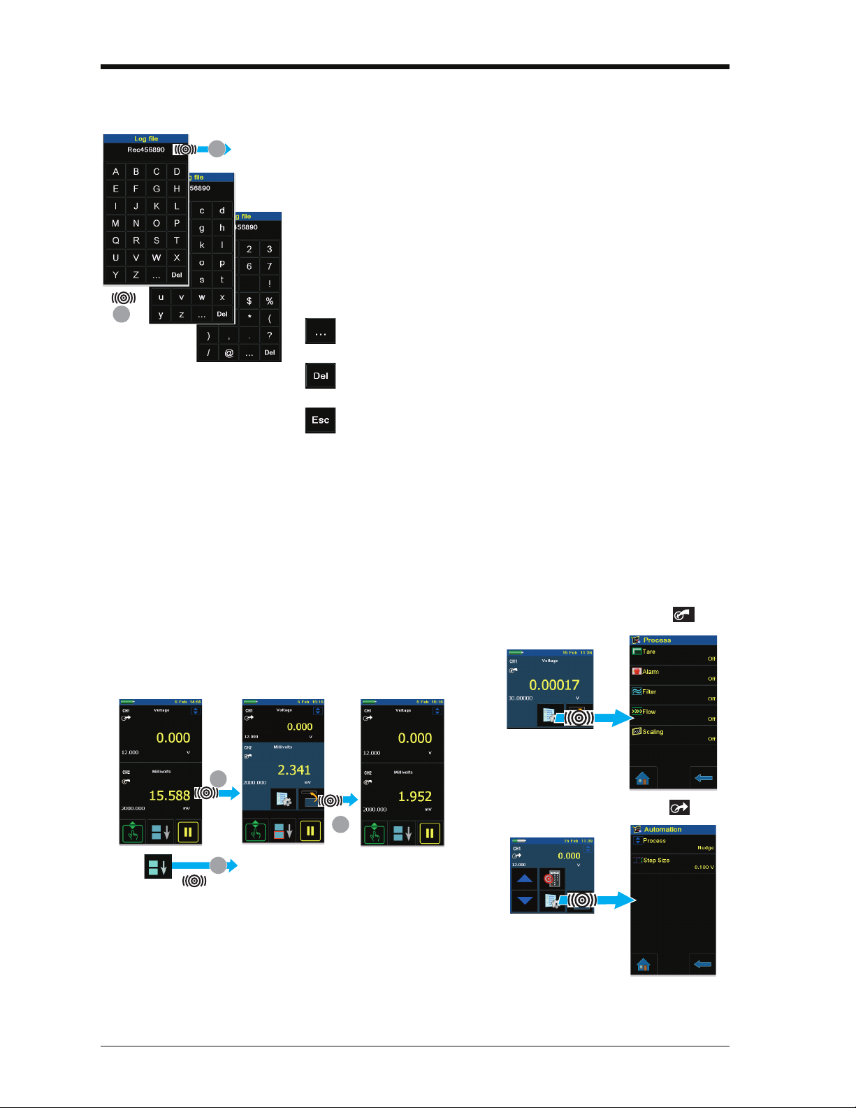
2.7.3 Enter text
There are alphanumeric key-pad displays for these items:
• Captions; see Section 2.8.4 (maximum: 15 characters; all
characters permitted)
• Filenames (maximum: 10 characters; no special characters)
1. Tap in the applicable characters.
2. To accept the data and go back to the previous display, tap
on the completed text in the data entry box.
Next key-pad: To use characters on the next key-pad
(upper case > lower case > numeric), tap this button.
Delete: To delete the last character in the data entry box,
tap this button.
Escape: If there are no characters in the data entry box,
the Esc button replaces the Del button. To leave the
key-pad and go back to the previous display, tap on the
Esc button.
2.7.4 Maximise/minimise a window
There can be up to 6 functions on the display. To set a Process
(measure operations), an Automation option (source
operations), or other Settings maximise the applicable function:
2-6 Prepare the instrument K0460 - [EN] English
Page 29
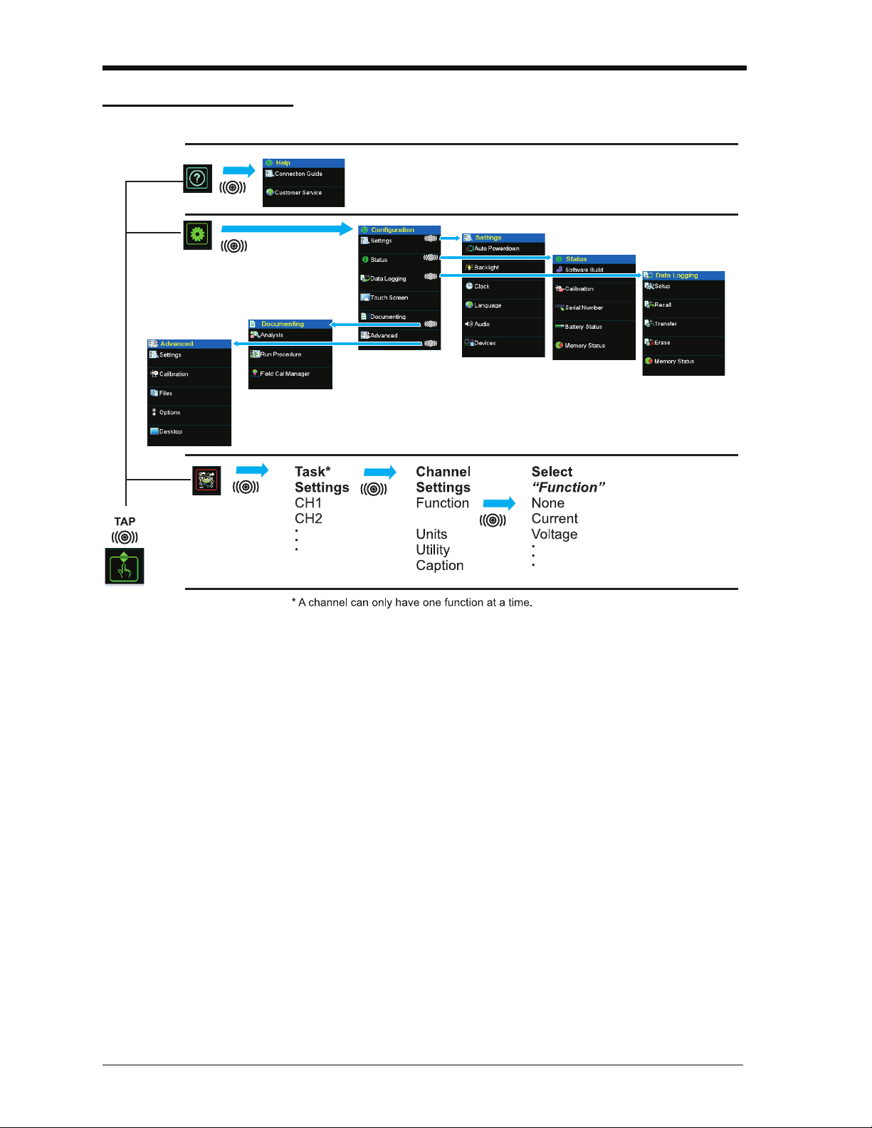
2.8 Menu sequence
Section 2.8.2
Chapter 6
Chapter 7
Section 2.8.1
Section 2.10
†
†
Normally, this is only necessary for versions with the Windows CE operating
system, Touch Screen enables the screen to be calibrated and re-centred.
Issue 1
[EN] English - K0460 Prepare the instrument 2-7
Page 30
Issue 1
TAP
Configuration
2
1
3
Settings
3
B
C
D
E
A
F
A
B
C
D
F
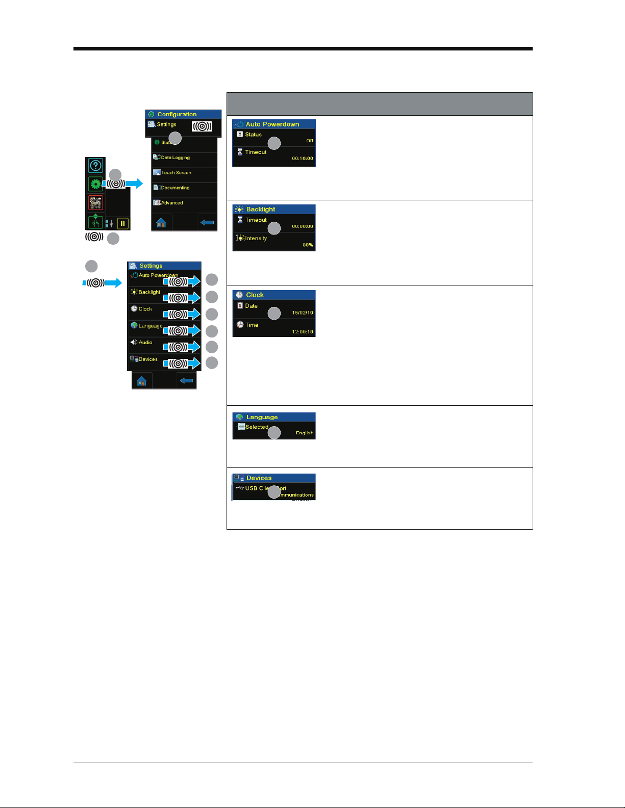
2.8.1 Procedure to set the basic operations:
Description
Status: On or Off
Timeout: 00:02:00 to 01:00:00 hours:minutes:seconds (hh:mm:ss)
Timeout: 00:02:00 to 02:00:00 hours:minutes:seconds (hh:mm:ss)
Intensity: 20, 40, 60, 80, 100%
Sets the power off automatically after the
specified Timeout period. To save the battery
power, set this to On.
Sets the backlight. Low values save battery
power; see Section 2.5.5 (Operating time).
Sets the date and time. The calibration function
uses this to give calibration messages.
Date: day/month/year (dd/mm/yy) OR month/day/year (mm/dd/yy).
The format is factory configured.
Time: 24 hour;
hours:minutes:seconds (hh:mm:ss)
Sets the language.
Selected: English (Other languages to be released).
Sets the communications using the USB port.
Communications: Storage device, communications, active sync.
2-8 Prepare the instrument K0460 - [EN] English
Page 31

2.8.2 Procedure to see the instrument status
TAP
Configuration
2
1
3
Status
The amount of memory available (in MB and as a
% of the total on the device): SD Card (internal).
Charging or battery-powered, and the amount of
charge in 1% increments.
The date of the next calibration.
CH1:
source
CH2:
measure
TAP
2
1
C
B
A
A
2.8.3 Procedures to make Task selections
When first using the calibrator, there are default measure
and source functions on the display:
• CH1 settings: RTD source, RTD type is PT100, scale is °C;
Automation is Nudge; see Chapter 3.
Issue 1
• CH2 settings: Current measure, see Chapter 3.
Procedure Overview Use the Tas k menu to complete these procedures:
• Set the calibrator functions on the display: item ; see
Section 2.8.4.
a. CH1: Channel 1 electrical function: Choose one option:
None Resistance
Current RTD
Voltage CJ
Millivolts Observed*
TC (°C/°F)
TC (mV)
Frequency
b. CH2: Channel 2 electrical function: Choose one option:
None Voltage
Current Millivolts
Current (24V) Observed*
[EN] English - K0460 Prepare the instrument 2-9
Page 32

Issue 1
Note: * Observed (Only
available as a source
option). Use this option to
make a manual record of
the readings on another
instrument; see
Section 2.9.3.
B
Continued
C
c. * Pressure function (P1): for the PV 62x-IS pressure
stations, refer to user manual - K0462; for the MC 620-IS
module carrier, see Chapter 4.
d. * Pressure function (P2): the MC 620-IS module carrier
can use P1 and/or P2; see Chapter 4.
e. HART function: HART device communications; see
Chapter 8.
• If applicable, change the Units for the function: item ;
see Section 2.8.5.
• If applicable, set a Utility for the function: item
a. Max/Min/Avg; see Section 2.8.6.
b. Switch Test: CH1, P1, P2 and IDOS functions use the
CH2 switch connections; CH2 functions use the CH1
switch connections. See Chapter 3.
c. Leak Test (Pressure options only); see Chapter 4.
Note: Making the connections for a switch on CH1 or CH2
means another function cannot be set on that channel.
2-10 Prepare the instrument K0460 - [EN] English
Page 33

2.8.4 Set a function
TAP
Select the function list
(Measure or Source)
Task Settings
Task Se t t i n g sSelect Function Channel Settings
1
2
3
4
97 8
5
Channel Settings
Source
Measure
6
Section 2.8.5
(Units)
Section 2.8.6
(Utility)
Section 2.7.3
(Caption text)
Issue 1
This example shows the sequence to set the Channel 1 (CH1)
function. It is a similar procedure for other functions.
[EN] English - K0460 Prepare the instrument 2-11
Page 34

Issue 1
Channel Settings Task Settings
7 8
TAP
Task Settings
1
2
4
5
6
3
Channel Settings
Channel Settings Task Settings
7
8
TAP
Task Settings
1
2
3
4
Channel Settings
5
6
Press the “reset” button to get a
new set of values.
2.8.5 Set the units
If a function has alternative units, another unit can be set. If
there are no alternatives, the area is shown grey.
2.8.6 Set up a utility: Maximum/Minimum/Average example
This example shows the sequence to set the Max/Min/Avg
utility. Use the same procedure for these options:
• Switch Test; see Chapter 3.
• Leak Test (pressure options only); see Chapter 4.
2-12 Prepare the instrument K0460 - [EN] English
Page 35

Issue 1
1
A
TAP
A
1
B
TAP
B
1
C
C
D
2
1
D
2.9 Measure and source operations
After setting the measure and source functions required on the
display (see Section 2.8.3), these procedures can be set:
• If necessary, change the Process for the CH1 and/or CH2
measure functions (item ) including:
Tar e, Alarm, Filter, Flow, Scaling; see Section 2.9.1.
For more optional Settings for the TC, Frequency, and RTD
functions; see Chapter 3.
• If necessary, change the Automation options for the CH1
and/or CH2 source functions (item ) including:
Nudge, Span Check, Percent Step, Defined Step, Ramp;
see Section 2.9.2.
For more optional Source Settings for the TC, Frequency,
and RTD functions; see Chapter 3.
For other Settings for Observed functions; see
Section 2.9.3.
• If necessary, change the Settings for the pressure function
(item ):
a. Process (Tare, Alarm, Filter, Flow, Scaling); see
Section 2.9.1.
b. Leak Test (Only when the function is set-up with this
Utility - Section 2.8.6); for operation, see Chapter 4.
c. Zero; see Chapter 4.
• If necessary, change the Configuration (item ) including:
Data Logging (Chapter 6), Documenting (Chapter 7), and
Advanced options (Section 2.10).
• When all the software selections are complete, make the
applicable connections (electrical and/or pressure).
Examples:
a. Electrical operations (Chapter 3).
b. Pressure operations with the MC 620-IS module carrier
(Chapter 4).
c. Pressure operations with a PV 62x-IS pressure station
(refer to the user manual - K0462).
[EN] English - K0460 Prepare the instrument 2-13
Page 36

Issue 1
Set the tare to the reading on the display.
Set On or Off.
Shows the stored tare value.
Tap it to set another value.
Previous: Back one display.
Home: Back to start.
1
2
3
TAP
*Set the low alarm value.
Set On or Off.
*Set the high alarm value.
*Default (low/high) = Range limits.
Previous: Back one display.
Home: Back to start
Alarm state
1
2
3
2.9.1 Set the Process options (measure )
Note: Section 2.7 (Display operation) shows how to set and
change the values on the display.
Tar e Use Tare to set a temporary value for zero. This makes an
adjustment to all subsequent readings on the display.
Alarm: When the alarm activates and displays the reading in red.
2-14 Prepare the instrument K0460 - [EN] English
Page 37

Filter: Set the Band and the Time Constant for the low pass filter:
Set the band (%FS). See Definitions.
Set On or Off.
Set the time constant. See Definitions.
Previous: Back one display.
Home: Back to start.
1
2
3
TAP
Set On or Off.
Previous: Back one display.
Home: Back to start.
1
2
3
TAP
Definitions
Band: The filter compares each new value with the
previous value. If the new value is outside the
band, it is not filtered.
Issue 1
Time
Constant:
This sets the cut-off frequency for the filter.
Higher value (in seconds) = more filtering.
Flow: (Square root function)
[EN] English - K0460 Prepare the instrument 2-15
Page 38

Issue 1
Set a scale for
Point 1 and Point 2.
Set On or Off
Set a label name.
Previous: Back one display.
Home: Back to start.
1
2
3
1
TAP
1
TAP
Scaling:
2.9.2 Set the Automation options (source )
Note: Section 2.7 (Display operation) shows how to set and
change the values on the display.
Nudge
Span Check
Description
Process: Nudge; Values to set: Step Size.
Use these buttons to increase or decrease the output
value. Increments = Step size.
Use this button (set-point) to set the output value.
Description
Process: Span Check; Values to set: Low, High, Dwell
Use these buttons to change the value manually from
High to Low.
Use the start and stop buttons to change the value
automatically from High to Low.
Dwell sets the period between each change. The cycle
repeats automatically.
2-16 Prepare the instrument K0460 - [EN] English
Page 39

Percent Step
1
TAP
1
TAP
1
TAP
Defined Step
Issue 1
Description
Process: Percent Step;
Values to set: Low, High, Step Size (%FS), Dwell, Auto Repeat (On/Off).
Use these buttons to change the value manually by the
specified Step Size.
Use the start and stop buttons to change the value
automatically by the specified Step Size.
Dwell sets the period between each change.
Description
Process: Defined Step;
Values to set: Low, High, Step Size, Dwell, Auto Repeat (On/Off).
Use these buttons to change the value manually by the
specified Step Size.
Use the start and stop buttons to change the value
automatically by the specified Step Size.
Dwell sets the period between each change.
Ramp
Description
Process: Ramp;
Values to set: Low, High, Travel, Dwell, Auto Repeat (On/Off).
Use the start and stop buttons for this process. Travel
sets the duration of the Ramp.
Dwell sets the period between each change in direction.
2.9.3 Set the Observed settings (source )
The Observed function is available as a Source on the task
selections: CH1, CH2, P1, P2. To set the Observed function,
see Section 2.8.4.
[EN] English - K0460 Prepare the instrument 2-17
Page 40

Issue 1
2
1
See Section 2.10.1.
Hart On or Off; see Chapter 8. Standards sets
IPTS 68 or ITS 90; see Chapter 3
Lists options installed.
See Section 2.10.2.
3
TAP
Goes back to Windows desktop.
1
TAP
2
2.10 The Advanced menu options
The Advanced menu provides settings and use of options:
• Settings • Calibration
• Files • Options
2.10.1 Advanced: Calibration options
There are two calibration menus that can be used:
Menu to calibrate the
DPI 620-IS
1. Enter the calibration PIN: 4321.
2. Tap the “Accept” button and continue with these operations:
• Calibrate the different measure and source channels on the
DPI 620-IS calibrator.
Contact us at: www.gesensinginspection.com
• Change the calibration PIN and then enable it, confirm the
new PIN.
• Set the next calibration date and/or set the Notification
option. If Notification is On and calibration is overdue, the
display shows “Calibration due ... ” message at the end of
the power on sequence.
2-18 Prepare the instrument K0460 - [EN] English
Page 41

Issue 1
1
TAP
2
Menu to upgrade the
DPI 620-IS software and
To use the most up-to-date software and firmware on the
DPI 620-IS calibrator, visit the GE website:
firmware
Follow the website instructions, use this menu to upgrade:
• Connect the instrument to be upgraded to a PC. Copy the
Note: Make sure the battery is fully-charged before starting the
upgrade process.
2.10.2 Advanced Setup options
FILES
Use this menu to save and recall personal settings, instrument
calibration settings and other standard instrument operations.
Save: After setting up the functions needed on the display
(Section 2.8.3) and all the measure and source operations
(Section 2.9), save the settings to a file.
www.gesensinginspection.com
files to the instrument’s storage memory (make sure the
instrument is in storage mode).
2.11 The Help menu
Recall: To use the specified settings again, select the
applicable filename from the list.
Erase One File: This deletes one file from the list. Confirm the
file to delete.
Clear User Settings: This clears user settings, they are
replaced by default (factory) settings.
Memory Status: The amount of memory available (in MB and
as a % of the total on the device): internal memory; SD card.
The Help menu includes electrical connection diagrams to help
set-up and use the electrical functions on channel 1 (CH1),
channel 2 (CH2).
[EN] English - K0460 Prepare the instrument 2-19
Page 42

Issue 1
2-20 Prepare the instrument K0460 - [EN] English
Page 43

Issue 1
TAP
2
1
A
B
C
Chapter 3: Electrical operations
3.1 Introduction
3.2 Measure and source operations
3.2.1 Procedure overview
This section gives examples of how to connect and use the
instrument for these operations:
• To measure and source electrical values.
Before starting:
• Read and understand the “Safety” section.
• Do not use a damaged instrument.
Note: Use only original parts supplied by the manufacturer.
When using the calibrator for the first time, there are default
measure and source functions on the display; see
Section 2.8.3.
To use the calibrator, complete these procedures:
• Set the required calibrator functions on the display: item
; see Section 2.8.3. This includes:
a. CH1: Channel 1 electrical function (measure or source).
b. CH2: Channel 2 electrical function (measure or source).
c. Pressure function (P1 and/or P2): for the MC 620-IS
module carrier, see Chapter 4; for the PV 62x-IS
pressure stations (P1 only), refer to user manual - K0462.
d. Other functions (maximum: 6 functions).
• If necessary, change the Units for the function: item ;
see Section 2.8.5
• If necessary, set a Utility for the function: item ; see
Section 2.8.6
a. Max/Min/Avg
b. Switch Test
c. Leak Test (pressure options only)
[EN] English - K0460 Electrical operations 3-1
Page 44

Issue 1
1
D
TAP
1
E
TAP
D
E
2
Maximum: 30V
Source current on
channel 1 (CH1)
Range: 0 to 24 mA
Automation: Nudge
(Section 2.9.2)
2
Maximum: 30V
1
B
3
Measure current on
channel 1 (CH1)
Range: ±55 mA
A
1
• If necessary, change the Process for the CH1 and/or CH2
measure functions: item
This includes: Tar e, Alarm, Filter, Flow, Scaling; see
Section 2.9.1.
There are more optional Settings for the TC, Frequency, and
RTD functions.
• If necessary, change the Automation options for the CH1
and/or CH2 source functions: item
This includes: Nudge, Span Check, Percent Step,
Defined Step, Ramp; see Section 2.9.2.
There are more optional Source Settings for the TC,
Frequency, and RTD functions.
There are other Settings for Observed functions; see
Section 2.9.3.
• When all the software selections are complete, make the
applicable electrical connections.
3.2.2 Example procedure: Measure or source current
These examples (A and B) show Channel 1 (CH1) set-up to
measure or source a current with external loop power.
Note: Using Channel 2 (CH2) connectors, use Channel 2 to
measure or source these ranges with internal or external loop
power (internal loop power = 24 V).
3-2 Electrical operations K0460 - [EN] English
Page 45

1. Set the applicable software options; see Section 3.2.1
2
Measure DC millivolts on
channel 1 (CH1)
Range: ±2000 mV (DC)
1
B
Measure DC volts on
channel 1 (CH1)
Range: ±30 V (DC)
A
1
21
3
Source DC volts on
channel 1 (CH1)
Range: 0 to 12 V (DC)
Automation: Nudge
(Section 2.9.2)
A
(Procedure overview).
2. Complete the electrical connections and continue with the
measure or source operation.
3. Source only (Automation): Set the applicable output value;
see Section 2.9.2.
3.2.3 Example procedure: Measure DC voltage
These examples (A and B) show Channel 1 (CH1) set-up to
measure a DC voltage.
Note: Using Channel 2 (CH2) connectors, use Channel 2 to
measure these ranges.
Issue 1
3.2.4 Example procedure: Source DC voltage (CH1)
[EN] English - K0460 Electrical operations 3-3
1. Set the applicable software options; see Section 3.2.1
(Procedure overview).
2. Complete the electrical connections and continue with the
measure operation.
These examples (A and B) show Channel 1 (CH1) set-up to
source a DC voltage.
Page 46

Issue 1
Source DC millivolts on
channel 1 (CH1)
Range: 0 to 2000 mV (DC)
Automation: Nudge
(Section 2.9.2)
B 1
3
2
21
Measure frequency on
channel 1 (CH1)
Range: 0 to 5 kHz
Trigger level: 2.5 V
A
3
Source frequency on
channel 1 (CH1)
Range: 0 to 5 kHz
Waveform: Triangle
Amplitude: 5.0 V
Automation: Nudge
(Section 2.9.2)
2B
4
1
3
A
1. Set the applicable software options; see Section 3.2.1
(Procedure overview).
2. Complete the electrical connections.
3. To continue, set the applicable output value; see
Section 2.9.2.
3.2.5 Example procedure: Measure or source frequency signals
These examples (A and B) show Channel 1 (CH1) set up to
measure or source a frequency. This includes Hz, kHz and
counts (cpm or cph).
The selection of units sets the available range, for example:
Hz = 0 to 1000 Hz kHz = 0 to 5 kHz
3-4 Electrical operations K0460 - [EN] English
Example 1. Set the applicable software options; see Section 3.2.1
(Procedure overview).
2. Complete the electrical connections.
Page 47

3. If necessary, change the Trigger Level (Settings) and
3
B
21
Measure current on
channel 2 (CH2) with
24V loop power
Range: ±55 mA
A
Maximum: 24 mA
Source current on
channel 2 (CH2) with
24V loop power
Range: 0 to 24 mA
Automation: Nudge
(Section 2.11.2)
2B
3
1
continue with the measure operation.
Values to set:
Mode (Automatic/Manual);
Manual Level (trigger level value)
Example 1. Set the applicable software options; see Section 3.2.1
(Procedure overview).
2. Complete the electrical connections.
3. If necessary change the Source Settings and continue with
source operation.
Values to set:
Waveform (Square, Triangle, Sine);
Amplitude (Amplitude value)
4. Automation: Set the applicable output value; see
Section 2.9.2.
Issue 1
3.2.6 Example procedure: Measure or source current (24V loop power)
These examples (A and B) show Channel 2 (CH2) set up to
measure or source a current with 24V loop power.
1. Set the applicable software options; see Section 3.2.1
(Procedure overview).
[EN] English - K0460 Electrical operations 3-5
2. Complete the electrical connections and continue with the
measure or source operation.
3. Source only (Automation): Set the applicable output value;
see Section 2.11.2.
Page 48

Issue 1
21
Measure an RTD on
channel 1 (CH1)
Range: 850 °C
RTD Type: PT100
Connection: 4 wire
A
3
Simulate an RTD on
channel 1 (CH1)
Range: 850 °C
RTD Type: PT100
Connection: 4 wire
Automation: Nudge
(Section 2.9.2)
2B
4
1
3
3.2.7 Example procedure: Measure or simulate an RTD (or Resistance)
These examples (A and B) show Channel 1 (CH1) set-up to
measure or simulate an RTD. A 4-Wire configuration gives the
best accuracy; a 2-Wire configuration has the lowest accuracy
(4-Wire RTD shown).
Note: To measure or simulate resistance (
Resistance function.
Ω), set the
3-6 Electrical operations K0460 - [EN] English
Example A 1. Set the applicable software options; see Section 3.2.1
(Procedure overview).
2. Complete the electrical connections.
3. If necessary change the Settings and continue with the
measure operation.
Values to set:
RTD Type (Set the applicable RTD); see Tabl e A 1 (front
cover) for the available options.
Example B 1. Set the applicable software options; see Section 3.2.1
(Procedure overview).
2. Complete the electrical connections.
Page 49

3. If necessary change the Source Settings and continue with
21
Measure a TC temperature
on channel 1 (CH1)
Range: 1372 °C
TC Type: K Type
Cold Junction: 27.43
A
3
Simulate a TC temperature
on channel 1 (CH1)
Range: 1372 °C
TC Type: K Type
Cold Junction: 38.2
Automation: Nudge
(Section 2.9.2)
2B
4
1
3
source operation.
Automation: Set the applicable output value; see
Section 2.9.2.
Values to set:
RTD Type (Set the applicable RTD); see Tabl e A 1 (front
cover) for the available options.
3.2.8 Example procedure: Measure or simulate a thermocouple (or TC mV)
These examples (A and B) show Channel 1 (CH1) set-up to
measure or simulate a thermocouple temperature.
To measure or simulate TC millivolts, set the TC mV function.
Issue 1
[EN] English - K0460 Electrical operations 3-7
Example A 1. Set the applicable software options; see Section 3.2.1
(Procedure overview).
2. Complete the electrical connections.
Page 50

Issue 1
3. If necessary change the Settings and continue with the
measure operation.
Values to set:
TC Type (Set the applicable TC).
CJ compensation (Mode: Automatic/Manual). Automatic
uses the internal cold junction. Use Manual mode for an
external cold junction.
CJ Value. For Manual mode, set an applicable value. The
value is not used in Automatic mode.
Example B 1. Set the applicable software options; see Section 3.2.1
(Procedure overview).
2. Complete the electrical connections.
3. If necessary, change the Source Settings and continue with
source operation.
Values to set:
TC Type (Set the applicable TC).
CJ compensation (Mode: Automatic/Manual). Automatic
mode uses the internal cold junction. Manual mode uses an
external cold junction.
CJ Value. For Manual mode, set an applicable value. The
value is not used in Automatic mode.
4. Automation: Set the applicable output value; see
Section 2.9.2.
3.2.9 Example procedure: Switch test
CH1, P1, P2 functions use the CH2 switch connections; CH2
functions use the CH1 switch connections.
Switch operation When setting the Switch Test utility on one channel, the
software automatically sets-up the other channel for the switch
connections.
Note: If there is a measure or source function on the switch
connection channel, it is automatically disabled with the screen
message “... Function Disabled”.
An attempt to set a measure or source function on the switch
connection channel, causes a screen message “... Function not
set”.
Example This example shows a thermocouple switch:
3-8 Electrical operations K0460 - [EN] English
Page 51

Issue 1
1
3
2
4
Start/Stop
Closed
Open
Reset
1. Set the applicable software options; see Section 3.2.1
(Procedure overview). This example shows one function:
• Thermocouple (TC) is set to source a temperature. The
Utility is set to Switch Test. The Automation is set to Ramp;
see Section 2.9.2.
2. Complete the electrical connections. Because it is a
Channel 1 function (TC), Channel 2 (CH2) must have the
switch connections.
3. For the Ramp process, set “High” and “Low” values that are
applicable to the switch value. Then, to get an accurate
switch value, set a long “Travel” period.
Use Start/Stop to start and stop the “Ramp” cycle. If
necessary, supply the output values in the opposite direction
until the switch changes condition again.
4. The display shows:
• the values to open and close the switch
• the hysteresis value
5. To do the test again, use the reset button.
[EN] English - K0460 Electrical operations 3-9
Page 52

Issue 1
3.3 Error indications
<<<<< Under range: The display shows this symbol for this condition:
>>>>> Over range: The display shows this symbol for this condition:
If the display shows <<<< (under range) or >>>> (over range):
• Make sure that the range is correct.
• Make sure that all the related equipment and connections
are serviceable.
Reading < Negative FS - (10% of negative FS).
Reading > Positive FS + (10% of positive FS).
3-10 Electrical operations K0460 - [EN] English
Page 53

Chapter 4: Pressure indicator
Caution: To prevent damage to the PM 620-IS, use
within the specified pressure limit on the label.
1
2
3
4
1
2
3
b)
a) MC 620-IS
5
a
1. Pressure connection (G1/8 or 1/8NPT) to attach
external pressure equipment.
2. Pressure and electrical connections for a pressure
module (PM 620-IS). These are self-sealing
pressure connections.
3. Two screws to attach the calibrator (DPI 620-IS).
4. Electrical connections for the calibrator
(DPI 620-IS).
5. Pressure module (PM 620-IS) with a pressure
connection, reference port (a) and a label. The
label includes:
Pressure range. Example: 20 bar g (g: gauge;
a: absolute); serial number (S/N); manufacturer:
name, address, website.
operation (MC 620-IS)
4.1 Introduction
4.2 Parts and assembly
This section gives examples of how to connect and use the
instrument to measure pressure with the module carrier
(MC 620-IS) and the applicable pressure modules (PM 620-IS).
To measure pressure with the IDOS UPM, refer to Chapter 3.
To make a fully integrated pressure calibrator instrument with
one of the three pressure stations, refer to the user manual for
the PV 62x-IS series of pressure stations - K0462
Before starting:
• Read and understand the “Safety” section.
• Do not use a damaged instrument.
Note: Use only original parts supplied by the manufacturer.
This figure shows the parts of the module carrier (MC 620-IS)
and pressure module (PM 620-IS).
[EN] English - K0460 Pressure indicator operation (MC 620-IS) 4-1
After attaching these items to the DPI 620-IS calibrator, a fully
integrated pressure indicator is formed that can measure
pneumatic or hydraulic pressure.
Page 54

Issue 1
a
b
4
3
2
1
Step Procedure
1. Align the two slots (a) on the calibrator with the two
posts (b) on the module carrier.
2. When the posts are fully engaged in the slots,
tighten the two screws until they are hand-tight.
3. Attach one or two PM 620-IS modules with the
correct range and type.
4. Tighten each one until it is hand tight only.
When this symbol flashes at the top of the display, it
shows there is communication between the module
and the calibrator.
1
2
NPT
a.
c.
(G) / BSPP
P ≤ 100 bar
b.
(G) / BSPP
3
4.2.1 Assembly instructions
4.3 Pressure connections
4.3.1 Procedure (to attach external equipment)
4-2 Pressure indicator operation (MC 620-IS) K0460 - [EN] English
WARNING: Pressurized gases and fluids are dangerous.
Before attaching or disconnecting pressure equipment,
safely release all the pressure.
The pressure ports for external equipment use “Quick fit”
pressure adaptors; see
Section 1.4 (Accessories). These are
easy to remove, change and install.
Step Procedure
1. Remove the adaptor from the pressure port.
2. Use an applicable seal for the pressure connection:
a. NPT type: Use an applicable sealant on the thread.
b. BSP (parallel) type: A bonded seal at the bottom is
recommended.
c. BSP (parallel) type, 100 bar (1500 psi) or less: a
bonded seal at the top is permitted.
3. Attach the adaptor to the external equipment; if
necessary use one of the alternative adaptors in
Section 1.4 (Accessories), then tighten to the applicable
torque.
Continued
Page 55

Step Procedure
4
TAP
2
1
3
A
3
C
B
A
B
C
1
D
D
4. Re-attach the adaptor to the MC 620-IS carrier and
tighten it until it is hand tight only.
Issue 1
4.4 Measure pressure
4.4.1 Procedure overview
When the pressure indicator assembly is complete
(Section 4.2.1), use the menus to set-up the necessary
operations.
To use the pressure indicator, complete these procedures:
• Set the calibrator functions to use on the display; see
Section 2.8.3. This includes:
a. Pressure function (P1 and/or P2): item .
b. CH1: Channel 1 electrical function (measure or source).
c. CH2: Channel 2 electrical function (measure or source).
d. Other functions (maximum: 6 functions).
• If necessary, change the Units for the function: item ;
see Section 2.8.5.
• If necessary, set a Utility for the function: item ; see
Section 2.8.6.
a. Max/Min/Avg
b. Switch Test
c. Leak Test; see Section 4.4.2.
• If necessary, change the Settings for the pressure function:
item .
a. Process (Tare, Alarm, Filter, Flow, Scaling);
see Section 2.9.1.
b. Leak Test (Only when the Utility is set); see
Section 4.4.2.
c. Zero Recommend - zero a gauge sensor before use; see
[EN] English - K0460 Pressure indicator operation (MC 620-IS) 4-3
Section 4.4.3.
d. Display If necessary, change the number of digits in the
display reading.
Page 56

Issue 1
1
3
4
Select Leak Test Select Test Time
Steps 5 and 6: Set the Test Time
+ Set the Wait Time.
TAP the window
(Maximise)
Select Settings
5
6
7
Start the test and let it
complete.
Go back to the Home window. Start the test
when the pressure system is set-up.
Stop the test (with no results)
2
4.4.2 Set-up a Leak Test
1) Set the Utility Set the Utility to Leak Test (Section 2.8.6).
• When all the software selections are complete, make the
applicable pressure and electrical connections. Examples:
Measure pressure (Section 4.4.4).
2) Set the Leak Test
options
When setting the Utility to Leak Test, set these options:
Wait Time: The time before the test starts in
hours:minutes:seconds (hh:mm:ss).
Test Time: The period of the leak test in
hours:minutes:seconds (hh:mm:ss).
Note: To set the Leak Test options, have a pressure module
correctly installed (Section 4.2.1).
4-4 Pressure indicator operation (MC 620-IS) K0460 - [EN] English
Page 57

4.4.3 Set the pressure module to zero
1
3
4
Select Zero
TAP the window
(Maximise)
Select Settings
5
Accept the adjustment value
Go back to the Home window.
2
See the new reading
p1
p2
p1
p2
P2
P1
31 2
Use this option to write a new zero pressure value to the
pressure module.
The sensor adjustment is permitted if it obeys this condition:
Adjustment ≤ 10% FS positive pressure value
Note: To make a temporary adjustment for zero, use the Tare
function; see Section 2.9.1.
Issue 1
(for the Sensor)
4.4.4 Example procedure: Measure pressure
[EN] English - K0460 Pressure indicator operation (MC 620-IS) 4-5
Page 58

Issue 1
1. Assemble the pressure indicator with the correct PM 620-IS
modules; see Section 4.2.1.
2. Set the applicable software options; see Section 4.4.1
(Procedure overview). This example shows two pressure
functions:
• Pressure functions P1 and P2 are set-up.
3. To attach the external equipment, see Section 4.3.1.
4.5 Error indications
<<<<< Under range: The display shows this symbol for this condition:
>>>>> Over range: The display shows this symbol for this condition:
If the display shows <<<< (under range) or >>>> (over range):
• Make sure that the range is correct.
• Make sure that all the related equipment and connections
are serviceable.
Reading < Negative FS - (10% of negative full-scale).
Reading > Positive FS + (10% of positive full-scale).
4-6 Pressure indicator operation (MC 620-IS) K0460 - [EN] English
Page 59

Chapter 5: Instrument
1
2
4
3
Step Procedure
1. Start the computer.
2. On the right-hand side of the instrument
(Figure 1-3), use the rubber recess to pull down
the cover for the connections.
3. Push the mini Type B end of the USB cable into
the USB socket on the instrument.
4. Set the instrument power on.
communications
5.1 Introduction
5.2 Connect to a computer (USB)
This chapter gives a description of these items:
• the procedures to connect the instrument to a computer with
the optional USB mini Type B cable.
For a full list of optional accessories, refer to Section 1.4.
A USB mini Type B connector connected between the
instrument and a computer can be used to download or upload
data to the SD card, see Chapter 6 (Datalog operation).
Note: If the power supply fails, the data will not transmit
correctly.
When the connections are complete, files can be moved
between the computer and the DPI 620-IS calibrator using
normal file manager software (for example, Windows Explorer).
[EN] English - K0460 Instrument communications 5-1
Note: The computer can get access to the internal memory of
the DPI 620-IS calibrator by using Active Sync.
Page 60

Issue 1
5-2 Instrument communications K0460 - [EN] English
Page 61

Chapter 6: Datalog operation
6.1 Introduction
6.2 Set-up
This section gives examples of how to log measurements with
time and date over a set time period or on a key press. Logged
data is stored in a user defined file. The instrument logs all the
tasks currently enabled.
Stores this data internally but can be downloaded (transferred)
through the mini Type B USB serial port. The data transfer to
the PC uses Active Sync.
To enter data logging select configuration menu and press data
logging.
To set the data logging process:
Selection Action
Filename Enter name using three-page screen alpha/numeric
key-pad.
Trigger Set to Key Press to activate on pressing of bottom
right key or Periodic set to activate on time set in
period.
Period Sets the time period of data recording using numeric
keys and HH:MM:SS format.
Start Starts data logging.
After data logging the data file can be used in the data logging
menu as follows:
[EN] English - K0460 Datalog operation 6-1
Page 62

Issue 1
Recall
Log Playback
Filename recalls data by filename from the list.
File details shows file name, start time and number of points.
Start begins playback of the selected file by pressing the
Pause/Play key.
Press and hold the Pause/Play key for at least two seconds to
reverse sequence.
Transfer
The stored data held in the internal memory can be transferred
to an external memory device:
USB serial port.
Erase
Erase one file Select file to erase.
Clear internal erases all files held in the instrument’s memory.
Clear SD card erases all data on the internal SD card.
Memory status
The amount of memory available (in MB and as a % of the total
on the device):
Internal SD card.
6-2 Datalog operation K0460 - [EN] English
Page 63

Issue 1
Comma separated file Data imported into a spreadsheet
6.3 Data Logging
6.4 Data handling
To data log:
To log measurements made by the instrument, set the required
tasks in Task Settings.
Select Configuration and select Data Logging.
Select Filename and enter a name using the three-page screen
alpha/numeric key-pad.
Select Trigger and either a time (Periodic) or key press
(play/pause).
Select start to set the data logging.
The display changes to the task screen with data logging
flashing at the top.
If necessary, press play/pause to increment the data logging.
At the end of data logging press the cancel key.
The instrument stores the recorded data.
Using the data logging menu, a data file can be replayed,
stored in a memory device or transferred to an external device;
see Section 6.2.
The data file can be imported into a number of spreadsheet
programs for analysis and graphic presentation.
Comma separation applies to this data.
[EN] English - K0460 Datalog operation 6-3
Page 64

Issue 1
6-4 Datalog operation K0460 - [EN] English
Page 65

Chapter 7: Documenting functions
2
1
TAP
Two Tasks
1
2
3
4
Set one channel as the Input (the DUT) and the other as the Reference.
Set the options A to E.
5
Documenting
Input
Reference
7
6
A
B
C
D
E
8
Continued
A
Analysis
7.1 Introduction
7.2 Analysis
This section gives examples of the documenting functions
available with the DPI 620-IS calibrator. There are two options:
Analysis (Section 7.2): This function compares the data from
two Channels on the DPI 620-IS calibrator: the device under
test (DUT) and a reference instrument.
It calculates the % span or % reading error for the device and
then gives a pass or fail indication.
Run Procedure (Section 7.3): This uses the Intecal
Calibration software (Optional item) to download a calibration
procedure.
Before starting:
• Read and understand the “Safety” section.
• Do not use a damaged instrument.
Note: Use only original parts supplied by the manufacturer.
To use the Analysis function, set the functions in the two
channels for comparison (Section 2.8.4). Then use these
procedures:
[EN] English - K0460 Documenting functions 7-1
Page 66

Issue 1
ABCDE
Set applicable values. When the Analysis
work is complete, tap on exit.
Start the
Analysis
9
10
Continued
from step 8
in specified
tolerance limit
not in specified
tolerance limit
Input and Reference
options
Channel type : Input or Reference
Scaling (Input only): Values for Reference High and Low
and Input High and Low. This sets the scale for the Analysis
function.
Error Type (Input only): % Span or % Rdg (Reading)
Linearity (Input only): Linear or Square Root
Tolerance (Input only): an applicable value for the
pass/fail calculation
When the Input and Reference options are set, start the
analysis.
7.3 Run a procedure
The Intecal calibration Procedure contains all the values to
calibrate a device under test (test points, ramp time). Use the
same calibration procedure for all the applicable devices under
test.
To use the Run Procedure function, the following items are
required:
• a copy of the Intecal Calibration Software. This is available
on the website at: www.gesensinginspection.com
There is a 30 day free trial.
• IO620-USB-RS232 (Intecal version 5 only). An adaptor to
connect the DPI 620-IS calibrator to the RS232 interface of
a computer.
• a DPI 620-IS calibrator device driver: available as a
download from our website.
7-2 Documenting functions K0460 - [EN] English
Page 67

Chapter 8: HART® device operations
8.1 Introduction
8.2 About HART
The DPI 620-IS calibrator can be used to communicate with
devices that use the HART
®
protocol:
• The Universal and Common Practice commands specified in
®
HART
This section includes procedures to use the HART
available in the calibrator.
Before starting:
revision 5 to 7.
®
functions
• Read and understand the “Safety” section.
• Do not use a damaged instrument.
Note: Use only original parts supplied by the manufacturer.
•
The HART® (Highway Addressable Remote Transducer) protocol
uses a digital signal on top of a standard 4 - 20 mA current loop
to get data to and from a HART
following are typical operations:
®
enabled field device. The
• read the primary variable and the analogue output.
• read the device serial number, type and supplier.
• get calibration data (upper and lower range values, sensor
limits, calibration date).
• do status and fault finding checks.
• change the device configuration (range, units, damping).
One HART device (a master device) starts and controls the
communications with commands. The field device (a slave device)
uses each command to make a change and/or send data back.
Two master devices are permitted: a primary master (usually the
main control and monitor system), and a secondary master
(usually a hand-held communicator). The DPI 620-IS calibrator
operates as a secondary master.
[EN] English - K0460 HART® device operations 8-1
Page 68

Issue 1
1
First steps • Set-up the HART® device, if loop power required, use CH2 for
current (24V), see section 14.
• If the loop is already powered and there is an external HART
resistor turn off channel 2. Connect the channel 2 mA+ and
mA- connections across the external HART resistor. See section
14.3.
®
resistor. This can be
Getting Device Identity
• If required, turn on the internal HART
selected by pressing icon.
• Press the HART
• The HART
• The HART
information on the bottom left hand side of the screen as the
program executes.
• As the HART
associated with the device and all the parameters of the
®
HART
transmitter are collected and loaded into memory.
®
button.
®
application starts-up.
®
applications operates and displays status
®
application operates the DPI 620-IS finds the DD
First screen
• A message box shows “Cannot find a device” if the device is not
connected. Refer to section 15.
• This is the first screen displayed by the instrument showing
®
concise information like Windows
Note:
The following screens are from the DPI 620, the screens for the DPI
620-IS will be issued later. Items in black (below) will be changed to
white for the DPI 620-IS.
menu tree structure.
• Online = summary view displaying the parameters and
variables of interest.
Items in red - read only
Items in blue - DPI 620-IS channel data
Items in black - can be edited.
8-2 HART® device operations K0460 - [EN] English
Page 69

Issue 1
Variables
Launches a data entry screen
Methods
Only a single tap on the screen is required to open any item in
black or open any folder.
Terminology PV = Digital Value of Primary Variable (i.e. this is the parameter that
the transmitter measures - pressure, current, voltage).
PV AO = Digital Value of Primary Variable mA current.
DPI 620-IS CH1 = Analogue Value of Primary Variable (actual
calibrated value).
DPI 620-IS CH2 = Analogue value of Primary Variable mA current
(actual calibrated value).
DPI620 P1, P2 and IDOS reflect the analogue pressure values
measured by the relevant pressure ports on the DPI620-IS.
Range Values PV LRV = Lower range value of Primary Variable.
PV URV = Upper range value of Primary Variable.
Example: Transmitter under test has a range of -200°C to +800°C.
Setting the LRV to -20°C (zero value) and URV to +20°C (span value)
allows re-ranging the transmitter (zero & span) to specified limits.
The PV % of range in this example for a PV = 0°C is equal to 50%.
Minimise button.
• Switch between screens by selecting minimise
button.
• This allows switching between Windows to
review and adjust the PV during calibrations.
[EN] English - K0460 HART® device operations 8-3
Page 70

Issue 1
Method
• Any item that has got a method icon
executes a method window to prompt with
on-screen instructions for performing a test or
calibration.
Menu Bar - device connection - pressing this allows the user to
connect to a transmitter.
- software version - pressing this allows the user to identify
the DK0397 software version.
- preferences - pressing this allows the user to change the
search by poll address short tag or long tag.
- commit - pressing this allows the user to commit (write
data) to the transmitter anything highlighted in yellow will
change.
- undo - pressing this allows the user to undo any changes
that are highlighted in yellow that were made to the local
variables in SDC625.
Review menus This is the ideal starting point for finding out information on the
®
configuration of the HART
transmitter. It provides details of the
model, distributor, tag, serial number, sensor & trim limits, alarm
parameters, saturation limits, damping and span limits etc.
8-4 HART® device operations K0460 - [EN] English
Page 71

Self-test
Issue 1
• To confirm that the transmitter is functioning
correctly, navigate through the menus to the
self-test method button:
• Press the self-test button.
• Press OK and the self-test executes.
L
o
o
p
t
e
s
t
.
• To confirm that the transmitter is functioning
correctly navigate through the menus to the
loop test button:
• Press the loop test button.
• Press OK and the loop test executes.
• The loop test can be put into various modes,
typically 4 mA and 20 mA should be selected.
The Analogue value of Primary Variable mA
current (actual calibrated value) of the
transmitter can be seen by selecting the CH2
drop-down box. If this value needs adjusting
then use the analogue trim (sometimes referred
to as D/A trim) in the calibration menu.
Analog trim (D/A trim)
• Using the DPI 620-IS, an analogue trim can be performed on
the 4 to 20 mA loop without having to connect any external
reference meters.
• Navigate to the calibration folder and select the D/A trim
method. Follow the on-screen instructions.
[EN] English - K0460 HART® device operations 8-5
Page 72

Issue 1
mA
Sensor Trim
A
n
a
l
o
g
t
r
i
m
• Type the Analogue value of Primary Variable mA
current (actual calibrated value) into the box
using the key-pad and then press Set. Repeat
this process with 20 mA selected. This will
accurately calibrate the transmitter’s output 4
to 20 mA loop current.
• Using the DPI 620-IS, a sensor trim on most Primary Variables
can be performed without having to connect any external
reference meters. If the Primary Variable is a pressure device
use the DPI 620-IS and PV 62x-IS pressure generation stations
to provide the pressure source. Alternatively, use DPI 620-IS
and MC 620-IS to accurately measure pressure.
• Navigate to the calibration folder and select the sensor trim
method. Follow the on-screen instructions.
• In this example a lower trim has been selected.
The DPI 620-IS is set-up to source a Primary
Variable to the transmitter. CH1 has been
configured to output 0°C. This can be done by
selecting the Switch App button at the bottom
of the method window and configuring the DPI
620-IS to simulate an RTD at 0°C. The Analogue
Value of the Primary Variable can be seen by
selecting CH1 on the drop-down menu.
• Type the Analogue Value of the Primary Variable
(actual calibrated value) into the box using the
key-pad and then press Set. Repeat this
process with an upper trim value. This will
accurately calibrate the transmitter’s sensor
output.
8-6 HART® device operations K0460 - [EN] English
Page 73

Issue 1
Measure current on
channel 2 (CH2) with
24V loop power
Range: ±55 mA
HART
®
Function is set
250Ω resistor is set
e1
a
b
d
c
Set HART
Section 2.8.4
Set Current (24V); Measure
Section 2.8.4
Home display
TAP
Please note that the current
measured on Channel 2 for a
HART device should normally be
between 4 and 20 mA.
Preferences • Selecting the icon allows the changing of the poll address,
short tag or long tag of the transmitter. The DPI 620-IS is set by
default to use Poll Address 0 (zero) only. This can be changed
by selecting the appropriate search radio button or by entering
the tag name in the search field.
8.3 HART® Connections
8.3.1 Power supply from
the calibrator
Examine the power supply connections for the transmitter before
®
connecting the HART
transmitter to the DPI 620-IS calibrator.
In this example, the DPI 620-IS calibrator supplies the loop power
®
and a 250Ω HART
1. Set the functions for channel 2 and HART
resistor.
®
:
[EN] English - K0460 HART® device operations 8-7
Page 74

Issue 1
Measure current on
channel 2 (CH2)
Range: ±55 mA
HART Function is set
250Ω resistor is set
e
1
a
b
d
c
Set HART
Section 2.8.4
Set Current; Measure
Section 2.8.1
Home display
T
2. Set-up the HART® device, if loop power required, use CH2 for
current (24V).
If the loop is already powered and there is an external HART
resistor, turn off CH2. Connect CH2 mA+ and mA- connections
®
to the HART
If required, turn on the internal HART
resistor, see Section 1.3.
®
resistor. This can be
selected by pressing icon.
Press the HART
®
button and the application starts.
3. Complete the electrical connections and continue with the
®
HART
menu operation; see Section 8.4.
4. Complete the electrical connections and continue with the
®
HART
menu operation; see Section 8.4.
8.3.2 External loop power
In this example, there is an external power supply.
®
Set the functions for channel 2 and HART:
5. Set the HART® Resistor.
8-8 HART® device operations K0460 - [EN] English
Page 75

Issue 1
No functions
on channel 2 (CH2)
HART
®
Function is set
250Ω resistor is set to Off
d
c
Home display
a
b
1
TAP
Set HART
®
User Manual Section 2.8.4
Turn on the internal HART® resistor. This can be selected by
pressing icon.
6. Complete the electrical connections and continue with the
®
HART
menu operation.
8.3.3 Communicator
attached to a
network
In this example, the calibrator connects directly to a network.
There must be a 250Ω resistor in series with the loop power supply
®
and the HART
1. Set the function for HART
device.
®
:
[EN] English - K0460 HART® device operations 8-9
Page 76

Issue 1
8.4 Failed to find a
device
The following is a checklist of what to do.
• When using the DPI620-IS to supply power, make sure that the
®
internal HART
resistor is turned on.
• Check the preferences option and set this to find first , then
re-start the application. This will ensure that SDC625 finds a
device that is not at poll address 0.
• When supplying power to the transmitter, check that the loop
current measured on channel 2 is between 4 and 20 mA. In
alarm conditions it is possible for it to be parked at 21.5 mA or
3.9 mA. However, if the current measured by channel 2 is far
from these values, there must be a configuration fault.
• If the transmitter is powered externally with an external HART
resistor, ensure that channel 2 has been turned off.
®
8-10 HART® device operations K0460 - [EN] English
Page 77

Chapter 9: Maintenance procedures
9.1 Introduction
9.2 Clean the unit
9.3 Replace the
batteries
This section gives procedures to maintain the instrument in a
good condition. Return the instrument to the manufacturer or
an approved service agent for all repairs.
Do not dispose of this product as household waste. Use an
approved organisation that collects and/or recycles waste
electrical and electronic equipment.
For more information, contact one of these:
• our customer service department:
(Contact us at www.gesensinginspection.com)
• local government office.
Clean the case with a moist, lint-free cloth and a weak
detergent. Do not use solvents or abrasive materials.
To replace the batteries, refer to Section 2.5.
All the configuration options stay in memory.
[EN] English - K0449 Maintenance procedures 9-1
Page 78

Issue 1
9-2 Maintenance procedures K0449 - [EN] English
Page 79

Chapter 10: Calibration procedures
10.1 Introduction
Note: GE can provide a calibration service that is traceable to
international standards.
Return of the instrument to the manufacturer (recommended)
or an approved service agent for calibration.
When using an alternative calibration facility, make sure that it
uses these standards.
10.2 Before starting
To do an accurate calibration:
• use the calibration equipment specified in Table 10-1.
• calibrate in a stable temperature environment: 21 ± 1°C (70
± 2°F).
Note: Before starting a calibration procedure, leave the
instrument in the calibration environment for a minimum
period of two hours.
Table 10-1: Calibration equipment
Function Calibration equipment
(ppm = parts per million)
Current
(CH1 or CH2)
Voltage
(CH1 or CH2)
Millivolts
(CH1 or CH2)
OR
TC mV (CH1)
Frequency
(CH1)
Amplitude (source) Digital voltmeter (DVM)
Current (mA) calibrator.
Accuracy - Current measure/source; see
Volts calibrator.
Accuracy - Voltage measure/source; see Table 10-5/10-7.
mV calibrator.
Accuracy - Millivolts measure/source; see Table 10-4/10-6.
Accuracy - TC mV; see Table 10-12.
(measure) (source)
Signal generator
Total error: 0.3 ppm or better
Table 10-2/10-3.
Frequency meter
Total error: 0.3 ppm or better
Resolution: 8 digits (minimum)
[EN] English - K0460 Calibration procedures 10-1
Page 80

Issue 1
2
The display shows the
applicable instructions to
complete the calibration.
TAP
31
Select function
Select range
(if applicable)
Select channel
Table 10-1: Calibration equipment (Continued)
Function Calibration equipment
(ppm = parts per million)
Resistance
(CH1)
CJ
(CH1)
Pressure
(P1 or P2)
* Or an equivalent resistance simulator
Standard 0Ω resistor An ohmmeter or an RTD
*
Standard resistor (Ω): 100, 200, 300,
400, 1k, 2k, 4k
Total uncertainty: 20 ppm
- Calibrated K type thermocouple
Accuracy: 50 mK for -5 to 28°C (23 to 82.4°F)
- Thermocouple temperature reference unit (0°C)
Accuracy: 30 mK
An applicable pressure standard (primary or secondary):
Range 25 mbar/0.36 psi: total uncertainty of 0.015% reading or better
Ranges > 25 mbar/0.36 psi: total uncertainty of 0.01% reading or better
Before starting the calibration, make sure that the time and
date on the instrument are correct; see Section 2.8.1
(Procedure to set the basic operations:).
(measure) (source)
measurement system with the
specified excitation currents; see
Table 10-11.
10.3 Selection
sequence
To do a calibration on a measure or source function, use the
Advanced menu option; see Section 2.10 (The Advanced
menu options):
➤
Configuration ➤ Advanced ➤ Calibration ➤ [Enter PIN:
➤
4321]
Perform Calibration ➤
Then select a function and start the calibration. This example
shows the Current (measure) function:
10-2 Calibration procedures K0460 - [EN] English
Page 81

Issue 1
(FS = full-scale)
When the calibration is complete, set the next calibration date;
see Section 2.10.1 (Advanced: Calibration options).
10.4 Procedures
(CH1/CH2): Current
(measure)
1. Connect the applicable calibration equipment specified in
Table 10-1; for example: see Section 3.2.2 (Example
procedure: Measure or source current).
2. Let the equipment get to a stable temperature
(minimum: 5 minutes since the last power on).
3. Use the calibration menu (Section 10.3) to do a three-point
calibration (-FS, Zero and +FS) for each range: 20 mA and
55 mA.
4. To make sure the calibration is correct, select the applicable
Current (measure) function; see Section 3.2.2 and apply
these values:
• mA: -55, -25, -10, -5, 0 (open circuit)
Then mA: 0, 5, 10, 20, 25, 55.
5. Make sure the error is in the specified limits (Table 10-2).
Table 10-2: Current (measure) error limits
Applied
mA
Calibrator
uncertainty (mA)
Permitted
DPI 620-IS error (mA)
10.5 Procedures (CH1/CH2): Current (source)
±55 0.003 0.0055
±25 0.0025 0.0040
±20 0.00063 0.0022
±10 0.00036 0.0016
±5 0.00025 0.0013
0 (open circuit) 0.0002 0.0010
1. Connect the applicable calibration equipment in Table 10-1;
for example:
• CH1/CH2 (24 mA range): see Section 3.2.2 (Example
procedure: Measure or source current), example B.
• CH2 (-24 mA range only): see Section 3.2.6 (Example
procedure: Measure or source current (24V loop power)),
example B.
2. Let the equipment get to a stable temperature
(minimum: 5 minutes since the last power on).
[EN] English - K0460 Calibration procedures 10-3
Page 82

Issue 1
3. Use the calibration menu (Section 10.3) to do a two-point
calibration (Zero and FS):
• CH1 (one range): 24 mA.
• CH2 (two ranges): -24 mA and 24 mA.
4. To make sure the calibration is correct, select the applicable
Current (source) function; see Section 3.2.2 or Section 3.2.6
and apply these values:
• CH1/CH2 (24 mA range): 0.2, 6, 12, 18, 24.
• CH2 (-24 mA range): -0.2, -6, -12, -18, -24.
5. Make sure the error is in the specified limits (Table 10-3).
Table 10-3: Current (source) error limits
Source
mA
±0.2 0.00008 0.0010
±6 0.00023 0.0016
±12 0.00044 0.0022
±18 0.0065 0.0028
±24 0.0012 0.0034
Calibrator
uncertainty (mA)
Permitted
DPI 620-IS error (mA)
10-4 Calibration procedures K0460 - [EN] English
Page 83

Issue 1
10.6 Procedures (CH1/CH2): DC mV/Volts (measure)
1. Connect the applicable calibration equipment in Table 10-1;
for example: see Section 3.2.3 (Example procedure:
Measure DC voltage).
2. Let the equipment get to a stable temperature
(minimum: 5 minutes since the last power on).
3. Use the calibration menu (Section 10.3) to do a three-point
calibration (-FS, Zero and +FS) for the applicable set of
ranges:
mV (measure) ranges Volts (measure) ranges
• 200 mV • 20 V
• 2000 mV • 30 V
4. To make sure the calibration is correct, select the applicable
Millivolts or Voltage (measure) function; see Section 3.2.3.
5. Then apply the input values that are applicable to the
calibration:
• mV: -2000, -1000, -200, -100, 0 (short circuit).
Then mV: 0, 100, 200, 1000, 2000.
OR
• Volts (V): -30, -21, -20, -10, -5, 0 (short circuit).
Then volts (V): 0, 5, 10, 20, 21, 30.
6. Make sure the error is in the specified limits (Table 10-4 or
Table 10-5).
Table 10-4: Millivolts (measure) error limits
Applied
mV
±2000 0.051 0.14
±1000 0.040 0.1
±200 0.0051 0.017
±100 0.0040 0.0125
0 (Short circuit) 0.0036 0.008
Calibrator
uncertainty (mV)
Permitted
DPI 620-IS error (mV)
[EN] English - K0460 Calibration procedures 10-5
Page 84

Issue 1
10.7 Procedures (CH1 mV (measure)/Volts Source
1. Connect the applicable calibration equipment in Table 10-1;
Table 10-5: Voltage (measure) error limits
Applied
V
±30 0.00052 0.0021
±21 0.0004 0.0018
±20 0.00031 0.0009
±10 0.00016 0.00065
±5 0.00008 0.00053
0 (Short circuit) 0.000024 0.0004
Calibrator
uncertainty (V)
Permitted
DPI 620-IS error (V)
for example: see Section 3.2.6 (Example procedure: Source
DC voltage (CH1)).
2. Let the equipment get to a stable temperature
(minimum: 5 minutes since the last power on).
3. Use the calibration menu (Section 10.3) to do a two-point
calibration (Zero and +FS) for the applicable range:
mV (source) ranges Volts (source) ranges
• 2000 mV • 12 V
4. To make sure the calibration is correct, select the applicable
Millivolts or Voltage (measure) function; see Section 3.2.6.
5. Then set the output values applicable to the calibration:
• mV: 0, 100, 200, 1000, 2000 OR.
• Volts (V): 0, 3, 6, 9, 12.
6. Make sure the error is in the specified limits (Table 10-6 or
Table 10-7).
Table 10-6: Millivolts (source) error limits
Source
mV
0 0.0001 0.008
100 0.00046 0.0125
200 0.0009 0.017
1000 0.003 0.1
2000 0.006 0.14
Calibrator
uncertainty (mV)
Permitted
DPI 620-IS error (mV)
10-6 Calibration procedures K0460 - [EN] English
Page 85

Table 10-7: Voltage (source) error limits
Issue 1
10.8 Procedures (CH1): Frequency (measure/source)
Source
V
0 0.000004 0.00042
3 0.000010 0.0006
6 0.000018 0.00078
9 0.000027 0.00096
12 0.000036 0.0011
Calibrator
uncertainty (V)
Permitted
DPI 620-IS error (V)
It is only necessary to do one frequency calibration; use the
measure function or the source function.
Frequency calibration (measure function): With the
necessary calibration equipment, use this procedure:
1. Connect the applicable calibration equipment in Table 10-1;
for example: see Section 3.2.8 (Example procedure:
Measure or source frequency signals), example A.
2. Let the equipment get to a stable temperature (minimum: 5
minutes since the last power on).
3. Set-up the equipment with these conditions:
Signal generator: Output = 10V, unipolar,
square wave
Frequency = 990 Hz
DPI 620-IS: Input units = Hz
Input trigger level = 5 V
4. Use the calibration menu (Section 10.3) to do a one-point
calibration then do the calibration checks (step 5).
Frequency calibration (source function): With the
necessary calibration equipment, use this procedure:
1. Connect the applicable calibration equipment in Table 10-1;
for example: see Section 3.2.8 (Example procedure:
Measure or source frequency signals), example B.
2. Let the equipment get to a stable temperature (minimum: 5
minutes since the last power on).
[EN] English - K0460 Calibration procedures 10-7
Page 86

Issue 1
3. Set-up the equipment with these conditions:
Frequency meter: Gate time = one second
DPI 620-IS: Waveform = Square;
Amplitude = 10 V;
Frequency = 990 Hz
4. Use the calibration menu (Section 10.3) to do a one-point
calibration then do the calibration checks (step 5).
Calibration check 5. To make sure the frequency calibration is correct, set-up the
equipment to do one of these calibration checks:
• Frequency (measure) calibration check (Section 3.2.8):
Signal generator: Output = 10 V, unipolar,
square wave
DPI 620-IS: Input trigger level = 5 V
Units: Hz or kHz as specified in
Table 10-8 or Table 10-9.
• Frequency (source) calibration check (Section 3.2.8):
Frequency meter: Gate time = one second
DPI 620-IS: Units: Hz or kHz as specified in
Table 10-8 or Table 10-9.
6. Measure or source the specified values (Table 10-8 or
Table 10-9): Hz then kHz. Make sure the error is in the
specified limits.
Table 10-8: Hz error limits (measure/source)
Measure/
source Hz
100 0.0002 0.0023 0.0026
990 0.0005 0.0050 0.0053
5000 0.0002 0.00035 0.000185
Calibrator
uncertainty (Hz)
Permitted
DPI 620-IS error (Hz)
(measure) (source)
10-8 Calibration procedures K0460 - [EN] English
Page 87

Issue 1
10.9 Procedures (CH1): Frequency amplitude (source)
1. Connect the applicable calibration equipment in Table 10-1;
for example: see Section 3.2.8 (Example procedure:
Measure or source frequency signals), example B.
2. Let the equipment get to a stable temperature (minimum: 5
minutes since the last power on).
3. Set-up the DPI 620-IS with these conditions:
Source frequency = 0 (For direct current output);
Waveform = Square
4. Use the calibration menu (Section 10.3) to do a two-point
calibration:
point 1 = 0.2 V, point 2 = 12 V
5. To make sure the calibration is correct, set-up the
DPI 620-IS with these conditions:
Source frequency = 0 (For direct current output);
Waveform = Square
6. Set the specified values (Table 10-9). Make sure the error is
in the specified limits.
Table 10-9: Amplitude (source) error limits
Amplitude
Volts (V)
0.2 0.01 0.1
4.0 0.01 0.1
8.0 0.01 0.1
12.0 0.01 0.1
Note:
The calibrated amplitude is the positive (mark) voltage level.
The negative (space) voltage level is approximately -120 mV.
Calibrator
uncertainty (V)
Permitted
DPI 620-IS error (V)
[EN] English - K0460 Calibration procedures 10-9
Page 88

Issue 1
10.10 Procedures (CH1): Resistance (measure)
1. Let the equipment get to a stable temperature (minimum: 5
minutes since the last power on).
2. Use the calibration menu (Section 10.3) to do a two-point
calibration for each range.
• Range: 0-400Ω
a. Nominal zero ohms: Make a 4-wire connection to the 0Ω
resistor; see Section 3.2.9 (Example procedure: Measure
or simulate an RTD (or Resistance)), example A.
b. Nominal positive full-scale ohms: Make a 4-wire
connection to the 400Ω resistor; see Section 3.2.9 (A).
• Range: 400Ω-4kΩ.
a. Nominal 400 ohms: Make a 4-wire connection to the
400Ω resistor; see Section 3.2.9 (A).
b. Nominal positive full-scale ohms: Make a 4-wire
connection to the 4kΩ resistor; see Section 3.2.9 (A).
Note: Details of the true ohms option to be issued later.
3. To make sure the calibration is correct, select the applicable
Resistance (measure) function; see Section 3.2.9, (A).
4.
Make a 4-wire connection to the applicable standard resistor
(Table 10-10) and measure the value; see Section 3.2.9, (
A
5. Make sure the error is in the specified limits (Table 10-10).
Table 10-10: Resistance (measure) error limits
Standard
Resistor
0 (Short circuit) - 0.02
100 0.002 0.032
200 0.004 0.044
300 0.006 0.056
400 0.008 0.068
1k 0.02 0.30
2k 0.04 0.41
4k 0.08 0.64
* Or an equivalent resistance simulator
*
(Ω)
Resistor
uncertainty (Ω)
Permitted
DPI 620-IS error (Ω)
).
10-10 Calibration procedures K0460 - [EN] English
Page 89

Issue 1
10.11 Procedures (CH1): Resistance (source)
1. Connect the applicable calibration equipment in Table 10-1;
for example: see Section 3.2.9 (Example procedure:
Measure or simulate an RTD (or Resistance)), example B.
2. Let the equipment get to a stable temperature (minimum: 5
minutes since the last power on).
3. Use the calibration menu (Section 10.3) to do a two-point
calibration for each range.
• Range: 0-400Ω
• Range: 400Ω-2000Ω
• Range: 2kΩ-4kΩ
4. To make sure the calibration is correct, select the applicable
Resistance (source) function; see Section 3.2.9, (B).
5. Set the specified values (Table 10-11). Make sure the error
is in the specified limits.
Table 10-11: Resistance (source) error limits
Ohms
(Ω)
Excitation
(mA)
Calibrator
uncertainty (Ω)
Permitted
DPI 620-IS error
(Ω)
0 0.1 0.0014 0.014
100 0.1 0.0016 0.038
200 0.1 0.0021 0.062
300 0.1 0.0028 0.11
400 0.1 0.0035 0.31
1000 0.1 0.008 0.55
2000 0.1 0.016 0.86
4000 0.1 0.032 1.1
[EN] English - K0460 Calibration procedures 10-11
Page 90

Issue 1
10.12 Procedures (CH1): TC mV (measure or source)
Input
or output
1. Connect the applicable calibration equipment in Table 10-1;
for example: see Section 3.2.10 (Example procedure:
Measure or simulate a thermocouple (or TC mV)).
2. Let the equipment get to a stable temperature
(minimum: 5 minutes since the last power on).
3. Use the calibration menu (Section 10.3) to do a three-point
calibration (-10 mV, Zero and 100 mV) for the measure or
source function:
4. To make sure the calibration is correct, select the applicable
TC mV (measure) or (source) function; see Section 3.2.10,
and apply the necessary values:
• TC mV (measure): -10, 0 (short circuit).
Then TC (mV): 10, 25, 50, 100.
OR
• TC mV (source): -10, 0, 10, 25, 50, 100.
5. Make sure the error is in the specified limits (Table 10-12).
Table 10-12: TC mV (measure or source) error limits
Calibrator uncertainty
TC (mV)
Permitted
DPI 620-IS error (mV)
TC (mV) (measure) (source) (measure) (source)
-10 0.0036 0.00011 0.0085 0.0085
0 0.0036 0.0001 0.008 0.008
10 0.0036 0.00011 0.0085 0.0085
25 0.0036 0.00015 0.0091 0.0091
50 0.0037 0.00025 0.010 0.010
100 0.004 0.00046 0.0125 0.0125
10-12 Calibration procedures K0460 - [EN] English
Page 91

Issue 1
Set the Cal
Value:
10.13 Procedures (CH1): CJ (measure)
Note: Do the TC mV (measure) calibration (Section 10.12)
before the cold junction calibration.
1. Connect the applicable calibration equipment in Table 10-1;
for example: see Section 3.2.10 (Example procedure:
Measure or simulate a thermocouple (or TC mV)),
example A.
2. Set-up the DPI 620-IS calibrator:
Function = TC (measure);
TC Type = K Type
CJ Compensation; Mode = Automatic
3. Set the reference unit temperature: 0°C
4. Let the equipment get to a stable temperature
(minimum: 2 hours since the last power on).
5. Record these values:
• the thermocouple temperature given on the reference unit,
T (actual).
• the thermocouple temperature given on the calibrator,
T (measured).
• the CJ temperature given on the calibrator, CJ (measured);
for example: in Section 3.2.10 example (A),
CJ (measured) = 32.66.
6. Calculate the CJ (Cal Value) as follows:
CJ (Cal Value) = CJ (measured) - T (actual) + T (measured)
7. Use the calibration menu (Section 10.3) to do a one-point
calibration for the CJ (measure) function.
When the screen shows “Sampling complete. ... ”, set the
correct Cal Value = CJ (Cal Value) in step 6.
8. To make sure the calibration is correct, select the TC
(measure) function; see Section 3.2.10, (A).
9. Make sure the DPI 620-IS calibrator gives a thermocouple
temperature that agrees with the temperature on
the reference unit ±0.1°C (0.2°F).
[EN] English - K0460 Calibration procedures 10-13
Page 92

Issue 1
10.14 Procedures:
Pressure indicator
modules (PM
620-IS)
1. Assemble the pressure indicator with the necessary
PM 620-IS modules and connect the instrument to the
pressure standard; see Section 4.4.4 (Example procedure:
Measure pressure).
2. Let the equipment get to a stable temperature (minimum:
60 minutes since the last power on).
3. Use the calibration menu (Section 10.3) to do a two-point
calibration (Zero and +FS) or a three-point calibration (-FS,
Zero and +FS). Refer to Table 10-13.
Table 10-13: Calibration pressures
Ranges: g Nominal applied pressure
mbar (psi)
-FS † Zero +FS
≤ 700 mbar (10.0 psi) -FS 0 +FS
> 700 mbar (10.0 psi) -900 (-13.1) 0 +FS
† For a three-point calibration, do not apply more than -90% of
the specified FS for the unit.
Ranges: a
Nominal applied pressure
mbar (psi)
Zero +FS
350 mbar (5.00 psi) < 1.0 (0.02) +FS
2 bar (30.0 psi) < 5.0 (0.07) +FS
7 bar (100.0 psi) < 20.0 (0.29) +FS
20 bar (300.0 psi) < 50.0 (0.73) +FS
≥ 350 bar (5000 psi) Use atmospheric
pressure as zero.
+FS
4. To make sure the calibration is correct, select the applicable
pressure function; see Section 4.4.4, and apply these
pressure values:
• Ranges g: 0, 20, 40, 60, 80, 100 (%FS)
Then: Go back to 0 in the same steps.
Then (three-point calibration only):
-20, -40, -60, -80, -100 (%FS)
Then: Go back to 0 in the same steps.
• Ranges a: 0, 20, 40, 60, 80, 100 (%FS)
Then: Go back to 0 in the same steps.
10-14 Calibration procedures K0460 - [EN] English
Page 93

Issue 1
5. Make sure the error is in the specified limits; see the tables
for Gauge Ranges or Absolute Ranges given in the
datasheet (supplied on the CD: P/N UD-0002); use the
values in column “Total uncertainty ... “.
The specified values include an allowance for temperature
changes, reading stability for one year, and the uncertainty of
the standard used for calibration.
[EN] English - K0460 Calibration procedures 10-15
Page 94

Issue 1
10-16 Calibration procedures K0460 - [EN] English
Page 95

Chapter 11: General specification
11.1 Introduction
For a full specification of the DPI 620-IS calibrator and its
related accessories (MC 620-IS carrier, PM 620-IS module,
and PV 62x-IS pressure stations) refer to the datasheet
supplied on the CD (CD: P/N UD-0003).
Table 11-1: General specification
Display OLED: Colour display with touch-screen
Operating temperature -10 to 40°C (14 to 104°F)
Storage
temperature
Ingress Protection IP65 (DPI 620-IS calibrator only)
Humidity 0 to 90% relative humidity (RH) non-condensing
Shock/Vibration Def Stan 66-31, 8.4 cat III
EMC Electromagnetic compatibility: BS EN 61326-1:2006
Electrical safety Electrical - BS EN 61010:2001
Pressure safety Pressure Equipment Directive - Class: Sound Engineering Practice (SEP)
Approved CE Marked
-20 to 70°C (-4 to 158°F)
Battery power NiMH battery (GE Part number: IO620IS-Battery)
Capacity: 4000 mAh; Nominal voltage: 3.6 V
Charge temperature: 0 to 40°C (32 to 104°F)
If the charger senses the temperature is outside this range, it stops
charging.
Discharge temperature: -10 to 50°C (14 to 122°F)
Charge/discharge cycles: > 500 > 70% capacity
[EN] English - K0460 General specification 11-1
Page 96

Issue 1
11-2 General specification K0460 - [EN] English
Page 97

Customer service Visit our web site: www.gesensinginspection.com
Page 98

 Loading...