

Page 1
User Manual Druck DPI620 Genii
GE Measurement & Control
Druck DPI 620 Genii
Advanced Modular Calibrator
K0541
© 2014 General Electric Company. All Rights Reserved. Specifications are
subject to change without notice. GE is a registered trademark of General
Electric Company. Other company or product names mentioned in this
document may be trademarks or registered trademarks of their respective
companies, which are not affiliated with GE
Page 2

User Manual Druck DPI620 Genii
Contents
1 Overview ................................................................................................................... 9
1.1 Equipment in the Box ........................................................................................ 9
1.2 Optional Items ................................................................................................ 10
1.3 Observance of the User Manual .................................................................... 10
1.4 General Safety Precautions ............................................................................. 11
1.5 General Warnings ........................................................................................... 12
1.6 Electrical warnings .......................................................................................... 13
1.7 Pressure Warnings .......................................................................................... 16
1.8 Preparing the Instrument ............................................................................... 17
1.9 Install the Battery ............................................................................................ 17
1.10 Charge the Battery .......................................................................................... 19
Battery Charging Times ........................................................................... 19 1.10.1
1.11 Basic Modes .................................................................................................... 20
Power On ................................................................................................ 20 1.11.1
Power Off ................................................................................................ 20 1.11.2
Power up from Standby Mode ................................................................ 21 1.11.3
1.12 Druck DPI 620 Genii, Modes ........................................................................... 22
Dashboard navigation ............................................................................. 23 1.12.1
Set Date, Time and Language ................................................................. 24 1.12.2
Themes .................................................................................................... 24 1.12.3
Druck DPI 620 Genii Manual ................................................................... 24 1.12.4
Alarm Status ............................................................................................ 24 1.12.5
................................................................................................................................ 24
28 April 2014 K0541 issue 2 Page 2 of 200
Page 3

User Manual Druck DPI620 Genii
To View Alarms select: ................................................................................................ 25
1.13 Software and Firmware Upgrades .................................................................. 26
Viewing Software Revision ...................................................................... 26 1.13.1
Upgrading the Software .......................................................................... 26 1.13.2
1.14 Maintenance ................................................................................................... 31
Cleaning ................................................................................................... 31 1.14.1
1.15 Instrument Return .......................................................................................... 32
Returned Material Procedure for USA .................................................... 32 1.15.1
Returned Goods Procedure for Europe .................................................. 33 1.15.2
Instrument Disposal in the European Union ........................................... 34 1.15.3
1.16 Packaging for Storage or Transportation ........................................................ 35
Environment............................................................................................ 35 1.16.1
1.17 Marks and Symbols ......................................................................................... 35
2
Electrical
Operations
............................................................................................... 36
2.1 Basic Calibrator Operation .............................................................................. 36
Saving Tasks ............................................................................................ 37 2.1.1
Electrical Tasks ........................................................................................ 38 2.1.2
Favourites ................................................................................................ 40 2.1.3
Custom Task ............................................................................................ 41 2.1.4
2.2 Set the Function Utility Options ...................................................................... 44
Max/Min ................................................................................................. 44 2.2.1
Switch Test .............................................................................................. 45 2.2.2
Relief Valve.............................................................................................. 46 2.2.3
2.3 Measurement Display Options ....................................................................... 48
2.4 Example Procedure: Measure or Source Current ........................................... 50
2.5 Example Procedure: Measure DC Voltage ...................................................... 51
28 April 2014 K0541 issue 2 Page 3 of 200
Page 4

User Manual Druck DPI620 Genii
2.6 Example Procedure: Measure AC Voltage (CH1), 0 to 20 Vrms Only ............. 52
2.7 Example Procedure: Measure AC Voltage (CH1) with the AC Probe .............. 53
2.8 Example Procedure: Source DC Voltage (CH1) ............................................... 54
2.9 Example Procedure: Measure or Source Current with 24V Loop ................... 55
2.10
Example Procedure:
Measure or Source Frequency
Signals
........................... 57
2.11 Example Procedure: Measure/Simulate a Resistance Temperature Detector
(RTD) 59
2.12 Example Procedure: Measure or Simulate a Thermocouple (TC) ................... 61
2.13 Example Procedure: Switch Test ..................................................................... 63
2.14 Measure Pressure: IDOS Option ..................................................................... 66
IDOS Option Assembly Instructions ........................................................ 67 2.14.1
IDOS Function Procedures ...................................................................... 68 2.14.2
2.15 Error Indications .............................................................................................. 69
3 Pressure Indicator Operation (MC620) ................................................................... 70
3.1 Parts and Assembly ......................................................................................... 71
Assembly Instructions ............................................................................. 73 3.1.1
3.2 Pressure Connections ..................................................................................... 74
Procedure (Attaching External Equipment) ............................................ 74 3.2.1
3.3 Procedure Overview ....................................................................................... 76
3.4 Set up a Leak Test ........................................................................................... 79
3.5 Set the Pressure Module to Zero .................................................................... 81
3.6 Error Indications .............................................................................................. 82
4 Data Logging Operation .......................................................................................... 83
4.1
Set-up
.............................................................................................................. 85
4.2 Operation ........................................................................................................ 87
4.3 File Review ...................................................................................................... 87
28 April 2014 K0541 issue 2 Page 4 of 200
Page 5

User Manual Druck DPI620 Genii
4.4 Chart View ....................................................................................................... 88
4.5 File Management ............................................................................................ 89
Transfer ................................................................................................... 89 4.5.1
Erase ........................................................................................................ 90 4.5.2
Memory Status ........................................................................................ 90 4.5.3
4.6 Data
Format .................................................................................................... 91
5 Documentation ....................................................................................................... 92
5.1 Analysis ........................................................................................................... 92
5.2
Set-up
.............................................................................................................. 94
Define the Reference Channel ................................................................ 95 5.2.1
Define each Input Channel ...................................................................... 96 5.2.2
5.3 Analysis Function ............................................................................................ 98
5.4 Run Procedure ................................................................................................ 99
Sequence to Upload and Download File ............................................... 100 5.4.1
6 HART® Operations ................................................................................................. 101
6.1 HART® Menu Operations .............................................................................. 101
6.2 Start-up ......................................................................................................... 102
6.3 HART® Connections....................................................................................... 103
6.4 Power Supply from the Calibrator ................................................................ 103
6.5 External Loop Power ..................................................................................... 104
6.6 Communicator Attached to a Network ......................................................... 105
6.7 Use of Test Connections ............................................................................... 105
6.8 Viewing Primary Variables ............................................................................ 106
Device Polling ........................................................................................ 106 6.8.1
Viewing HART® Configuration ............................................................... 107 6.8.2
6.9 Start HART® SDC Application ........................................................................ 107
28 April 2014 K0541 issue 2 Page 5 of 200
Page 6

User Manual Druck DPI620 Genii
6.10 HART® Toolbar .............................................................................................. 110
6.11 Data Display .................................................................................................. 111
6.12 Editing Values ................................................................................................ 112
6.13 Executing Methods ....................................................................................... 114
Method Example - Self-test .................................................................. 115 6.13.1
Method Example - Analog Trim ............................................................ 116 6.13.2
6.14 Preferences ................................................................................................... 118
6.15 Failed to find Device ..................................................................................... 119
7 HART® Offline ........................................................................................................ 120
7.1 Introduction .................................................................................................. 120
7.2 Start-up ......................................................................................................... 120
7.3 Start HART® Offline ....................................................................................... 121
7.4 Create an Offline Configuration .................................................................... 122
Connected Configuration ...................................................................... 123 7.4.1
Disconnected Configuration ................................................................. 124 7.4.2
7.5 Edit an Offline Configuration ........................................................................ 125
7.6 Saving the Configuration ............................................................................... 127
7.7 Uploading the Configuration ........................................................................ 128
7.8 Working with Saved Configurations ............................................................. 128
Open HART Config ................................................................................. 128 7.8.1
Upload Config to Device ....................................................................... 128 7.8.2
Copy HART Config to USB ..................................................................... 128 7.8.3
Delete HART Config ............................................................................... 129 7.8.4
7.9 Further Operations ....................................................................................... 129
Delete All Configuration Files ................................................................ 129 7.9.1
Import Configuration Files from USB Memory stick ............................. 129
.2
28 April 2014 K0541 issue 2 Page 6 of 200
7.9
Page 7

User Manual Druck DPI620 Genii
8 Foundation™ Fieldbus ........................................................................................... 130
8.1 Introduction .................................................................................................. 130
8.2 Start up .......................................................................................................... 130
8.3 FOUNDATION™ Fieldbus Toolbar ................................................................. 133
8.4 Scanning For Devices .................................................................................... 135
Context Sensitive Menu ........................................................................ 137 8.4.1
Troubleshooting .................................................................................... 139 8.4.2
8.5 Device Focus View ......................................................................................... 140
8.6 The Navigation Menu Tree ........................................................................... 142
7.6.1 Block Header bar .......................................................................... 143 8.6.1
8.7 Functional Group View ................................................................................. 144
Displaying Parameter Help.................................................................... 146 8.7.1
Refreshing Data ..................................................................................... 147 8.7.2
Editing Values ........................................................................................ 148 8.7.3
Methods ................................................................................................ 149 8.7.4
8.8 Function Finder ............................................................................................. 150
8.9 Exporting Data to Main Genii Application .................................................... 152
Viewing Exported Variables in Channel Window .................................. 154 8.9.1
8.10 My Block ........................................................................................................ 155
8.11 Application Settings ...................................................................................... 157
Device Library ........................................................................................ 157 8.11.1
Options .................................................................................................. 158 8.11.2
Advanced .............................................................................................. 159 8.11.3
9 Calibration Procedures ......................................................................................... 160
9.1 Before Starting .............................................................................................. 160
9.2 Procedures (CH1/CH2): Current (measure) .................................................. 163
28 April 2014 K0541 issue 2 Page 7 of 200
Page 8

User Manual Druck DPI620 Genii
9.3 Procedures (CH1/CH2): Current (source) ..................................................... 166
9.4 Procedures (CH1/CH2): DC mV/Volts (measure) .......................................... 168
9.5 Procedures (CH1): DC mV/Volts (source) ..................................................... 170
9.6 Procedures (CH1): Frequency (measure/source) ......................................... 172
9.7 Procedures (CH1): Frequency Amplitude (source) ....................................... 178
9.8 Procedures (CH1): Resistance measure) ....................................................... 180
9.9 Procedures (CH1): True Ohms (measure) ..................................................... 182
9.10 Procedures (CH1): Resistance (source) ......................................................... 183
9.11 Procedures (CH1): TC mV (measure or source) ............................................ 185
9.12 Procedures (CH1): Cold Junction (TC method) and CJ (measure) ................. 187
9.13 Procedures (CH1): AC mV/Volts (measure) .................................................. 190
9.14 Procedures: Pressure Indicator Modules (PM 620) ...................................... 192
9.15 Procedures: IDOS UPM ................................................................................. 195
10 General Specification ........................................................................................ 196
10.1 Introduction .................................................................................................. 196
11 Manufacturer .................................................................................................... 199
12 Display Icons ..................................................................................................... 200
28 April 2014 K0541 issue 2 Page 8 of 200
Page 9

User Manual Druck DPI620 Genii
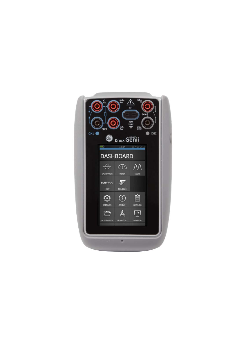
1 Overview
The Druck DPI620 Genii is a battery-powered instrument
for electrical measure and source operations and HART®
communications. The Druck DPI620 Genii also supplies the
power and user interface functions for all optional items.
The touch-screen displays up to six different parameters.
This version of the manual is applicable to software
revisions DK420 v2.01 and above.
1.1 Equipment in the Box
The following items are supplied with the Druck DPI 620
Genii:
• DC power supply
• Li-polymer battery
• Set of six test leads
• AC Probe
• Quick Start Guide
• Stylus
28 April 2014 K0541 issue 2 Page 9 of 200
Page 10

User Manual Druck DPI620 Genii
1.2 Optional Items
The items that follow are optional items which can be used
with the Druck DPI 620 Genii:
• Pressure Module Carrier, MC 620, this attaches directly
to the Druck DPI 620 Genii to make a fully integrated
pressure instrument.
• Pressure Module, PM 620, this attaches to the pressure
module carrier (MC 620) or a Pressure Station (PV 62X) to
enhance the pressure measurement functionality.
• Pressure Stations, PV 62X, if the Druck DPI 620 Genii is
installed in a Pressure Station, it becomes a fully
integrated pressure calibrator.
1.3 Observance of the User Manual
This manual contains safety and battery installation
information for the Druck DPI 620 Genii. It is the
responsibility of the customer, to make sure that all
personnel operating and maintaining the equipment are
correctly trained and qualified. Before operating or using the
equipment read and obey all sections, including all
WARNINGS and CAUTIONS given in the Quick Start Guide.
28 April 2014 K0541 issue 2 Page 10 of 200
Page 11

User Manual Druck DPI620 Genii
1.4 General Safety Precautions
Read and obey all the operator's local Health and Safety
regulations and Safe Working Procedures or Practices.
When doing a procedure or task:
• Use only the approved tools, consumable materials
and spares to operate and maintain the equipment.
• Read and obey all applicable WARNING signs.
• Make sure that:
All work areas are clean and clear of
unwanted tools, equipment and materials.
All unwanted consumable materials are
discarded in accordance with local health
and safety and environmental regulations.
28 April 2014 K0541 issue 2 Page 11 of 200
Page 12

User Manual Druck DPI620 Genii
1.5 General Warnings
• It is dangerous to ignore the specified limits for the
instrument or its related accessories. This can
cause injuries.
• If the equipment is used in a manner not specified
by the manufacturer, the protection provided by
the equipment may be impaired.
• Do not use the instrument in locations with explosive gas,
vapour or dust. There is a risk of an explosion.
• Make sure all equipment is serviceable.
• Use equipment only for the purpose for which it is
provided.
• Wear all applicable Personal Protective Equipment (PPE).
• Do not use sharp objects on the touch-screen.
28 April 2014 K0541 issue 2 Page 12 of 200
Page 13

User Manual Druck DPI620 Genii
1.6 Electrical warnings
• To prevent electrical shocks or damage to the instrument,
do not connect more than 30V CAT I between the
terminals, or between the terminals and the ground
(earth).
• External circuits should have appropriate insulation to
the mains.
• To prevent electrical shocks, use only the GE specified
AC probe (Part: IO620-AC) to measure AC voltages
that are more than 20 Vrms. Do not connect more
than 300V CAT II between the IO620-AC leads, or
between the leads and the ground (earth). Attach it to
the specified connections only.
• This instrument uses a Lithium-Polymer (Li-Polymer)
battery pack. To prevent an explosion or fire, do not
short circuit, do not disassemble, and keep it safe
from damage.
• To prevent an explosion or fire, use only the GE
specified battery (Part: 191-356), power supply (Part:
191-339) and battery charger (Part: IO620-CHARGER).
• To prevent battery leakage or heat generation, only
use the battery charger and power supply in the
temperature range 0°C to 40°C (32°C to 104°F).
• The power supply input range is 100 – 240Vac, 50 to 60Hz,
250mA, installation category CAT II.
• Position the power supply so not to obstruct the supply
disconnecting device.
28 April 2014 K0541 issue 2 Page 13 of 200
Page 14

User Manual Druck DPI620 Genii
• Note that the operating and storage temperature range
of the mains PSU does not match that of the DPI620.
Mains PSU operating temperature range 0°C to +40°C,
storage temperature range -40°C to +70°C.
• The DC input to the DPI620 Genii is rated at 5V (+/-5%).
Maximum current 2 Amps.
• To make sure the display shows correct data,
disconnect the test leads before power is set to on or
changing to another measure or source function.
• Make sure the power is OFF before connecting or
disconnecting the probe.
.
• Keep the probe and leads free from all contaminants
28 April 2014 K0541 issue 2 Page 14 of 200
Page 15

User Manual Druck DPI620 Genii
Overvoltage
Description
Overvoltage category I has the least severe
Overvoltage category II describes an electrical
The following summary of installation and measurement
overvoltage categories are derived from IEC61010-1.
The overvoltage categories indicate the severity of
overvoltage transients
Category
overvoltage transients. Generally CAT I
CAT I
equipment is not designed to be directly
connected to the mains supply. Examples of CAT I
equipment are process loop powered devices
installation where typically single phase
CAT II
equipment is connected. Examples of such
equipment are appliances and portable tools
28 April 2014 K0541 issue 2 Page 15 of 200
Page 16

User Manual Druck DPI620 Genii
1.7 Pressure Warnings
• Some liquid and gas mixtures are dangerous. This
includes mixtures that occur because of
contamination. Make sure that the equipment is safe
to use with the necessary media.
• To prevent a dangerous release of pressure, isolate
and bleed the system before disconnecting a
pressure connection.
• To prevent a dangerous release of pressure, make
sure that all the related pipes, hoses and equipment
have the correct pressure rating, are safe to use and
are correctly attached.
• To prevent damage to the Druck DPI 620 Genii, only
use it within the specified pressure limits.
• Do not exceed the maximum pressures stated in the
appropriate component manual for the unit under test.
• Reduce pressure at a controlled rate when venting to
atmosphere.
• Carefully de-pressurize all pipes to atmospheric
pressure before disconnecting and connecting to the
unit under test.
• Observe cleanliness when using the instrument.
• Severe damage can be caused if equipment
connected to this instrument is contaminated.
• Connect only clean equipment to the instrument. To
avoid any contamination, an external filter is
recommended.
28 April 2014 K0541 issue 2 Page 16 of 200
Page 17

User Manual Druck DPI620 Genii
1.8 Preparing the Instrument
On receipt of the instrument check the contents in the
box, listed in section 1.1. It is recommended to retain the
box and packaging for future use.
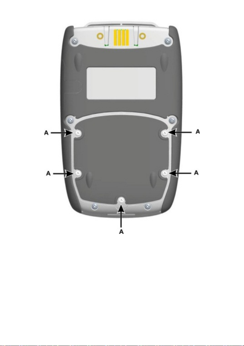
1.9 Install the Battery
1. Remove the five Pozidriv screws (A) (Ref: Figure 1-1).
2. Remove the battery cover.
3. Check the connections on the battery line up with the
connections in the battery compartment.
4. Place the battery in the battery compartment.
5. Replace the battery cover.
6. Secure the cover with the five Pozidriv screws.
28 April 2014 K0541 issue 2 Page 17 of 200
Page 18
User Manual Druck DPI620 Genii
Figure 1-1
28 April 2014 K0541 issue 2 Page 18 of 200
Page 19

User Manual Druck DPI620 Genii
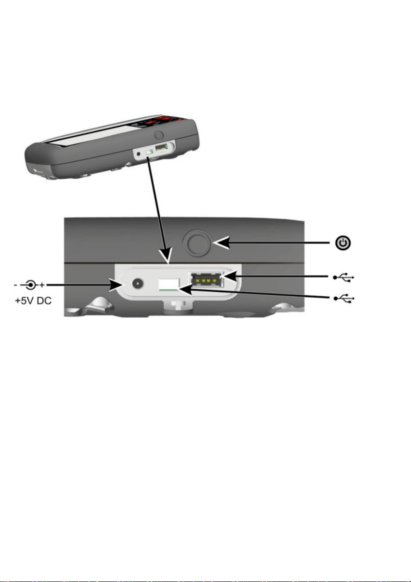
1.10 Charge the Battery
1. Connect the DC power supply into the +5V DC
connection on the side of the unit (Ref: Figure 1-3).
2. The battery can also be charged using the USB
connections (Ref: Figure 1-3).
3. The unit can be On or Off when charging. Charging
times may be longer if charging when the unit is
switched on.
Battery Charging Times 1.10.1
Charging Connection Charge Time
DC Power Supply 6.5 hours
External Battery Charger 6.5 Hours
28 April 2014 K0541 issue 2 Page 19 of 200
Page 20

User Manual Druck DPI620 Genii
1.11 Basic Modes Power On 1.11.1
From OFF – momentarily press the power button until the
display flashes (Ref: Figure 1-3) .
Power Off 1.11.2
Press and Release the Power Button:
The POWERDOWN OPTIONS window will be displayed
Figure 1-2 Powerdown Options
SWITCH OFF – Full power down of Druck DPI 620 Genii –
recommended if unit is not going to be used for several
hours (Requires full reboot on next power up)
STANDBY – DPI620G placed in standby mode – reduced
power consumption from operating mode – recommended
if unit is to be inactive for short periods. (Druck DPI 620 Genii
has fast turn on from STANDBY mode).
Note: SWITCH OFF can also be achieved by pressing and
holding the power button until the screen is blank.
28 April 2014 K0541 issue 2 Page 20 of 200
Page 21
User Manual Druck DPI620 Genii
Power up from Standby Mode 1.11.3
When powered-up from standby mode the instrument
always opens the last screen shown before going into
standby mode.
Figure 1-3
28 April 2014 K0541 issue 2 Page 21 of 200
Page 22

User Manual Druck DPI620 Genii
1.12 Druck DPI 620 Genii, Modes
The Druck DPI 620 Genii can be used as follows:
• Calibrator (with independent functions on each of six
channels).
- Data logging capabilities
- Documenting capabilities
• HART® Communicator.
• Foundation Field-bus Communicator.
28 April 2014 K0541 issue 2 Page 22 of 200
Page 23
User Manual Druck DPI620 Genii
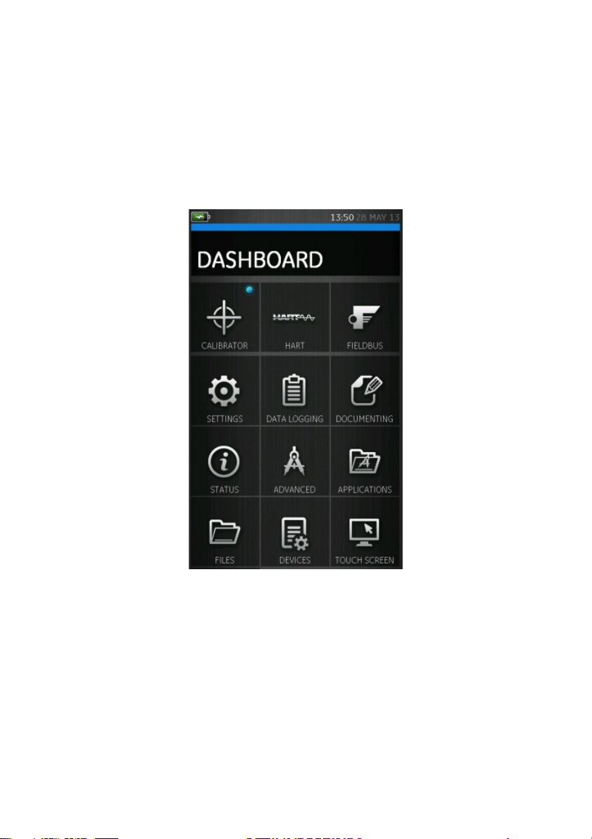
Dashboard navigation 1.12.1
The Dashboard is navigated by swiping a finger from top
to bottom while touching the screen. Functions screens
are navigated by swiping a finger from right to left while
touching the screen.
Figure 1-4 Dashboard
Note: Fieldbus is not installed on all units
28 April 2014 K0541 issue 2 Page 23 of 200
Page 24
User Manual Druck DPI620 Genii
Set Date, Time and Language 1.12.2
To access Date, Time and Language menus select:
DASHBOARD >> SETTINGS >> DATE
>> TIME
>> LANGUAGE
Themes 1.12.3
Two themes are available: Dark and Light; select the correct
theme for the light level. Select:
DASHBOARD >> SETTINGS >> THEME
Druck DPI 620 Genii Manual 1.12.4
Select the Help icon on the Dashboard to access the
manual. All the information required to operate the Druck
DPI 620 Genii, is in the Help section of the Dashboard
which is accessed by selecting:
DASHBOARD >> HELP
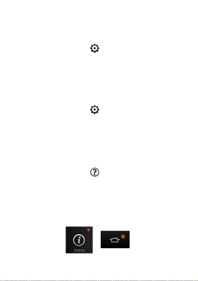
Alarm Status 1.12.5
An Alarm Status is indicated on the DASHBOARD with a Red
LED on the Status button and on the Home button on other
screens.
28 April 2014 K0541 issue 2 Page 24 of 200
Page 25
User Manual Druck DPI620 Genii
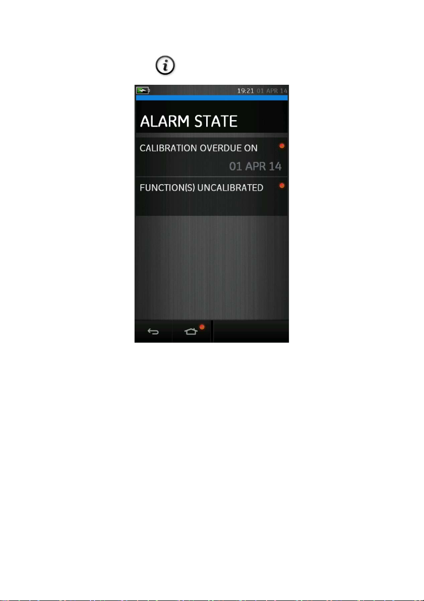
To View Alarms select:
DASHBOARD >> STATUS >> ALARM STATE
Figure 1-6 Alarm State
Selecting the Alarm will clear the indication until the next
power down.
28 April 2014 K0541 issue 2 Page 25 of 200
Page 26

User Manual Druck DPI620 Genii
1.13 Software and Firmware Upgrades Viewing Software Revision 1.13.1
The software revisions running on the Druck DPI 620 Genii
can be viewed by selecting:
DASHBOARD >> STATUS >> SOFTWARE BUILD
Note: If the software revision number is highlighted red then
an upgrade is available.
Upgrading the Software 1.13.2
Follow the website instructions to download the files onto
a USB flash memory device.
www.ge-mcs.com
1. Select:
DASHBOARD >> ADVANCED
2. Enter the calibration PIN: 5487
3. Select the button.
4. Select:
UPGRADE
5. Continue with one of these operations:
28 April 2014 K0541 issue 2 Page 26 of 200
Page 27

User Manual Druck DPI620 Genii
• Upgrade the Application software and SDC625
Application.
1. Copy the ‘AMC’ application folder into the root of
a USB flash memory device.
2. Put the USB flash memory device in the USB
type A connector.
3. Select:
APPLICATION
4. Follow the on-screen instructions.
Note: The SDC625 HART® Application can only be
upgraded as part of an application upgrade.
• Upgrade the Operating System and Bootloader
software.
1. Create a folder named ‘OS’ in the root of a USB
flash memory device.
2. Copy the files ‘DK418.nb0’ and ‘DK419.nb0’ into
the ‘OS’ folder.
3. Put the USB flash memory device in the USB
type A connector.
4. Select:
OPERATING SYSTEM
5. Follow the on-screen instructions.
Note: The bootloader can only be upgraded as part of
an operating system upgrade.
28 April 2014 K0541 issue 2 Page 27 of 200
Page 28

User Manual Druck DPI620 Genii
• Upgrade the HART processor Application and Boot
Loader
1. Create a folder named ‘HART’ in the root of a
USB flash memory device.
2. Copy the files ‘DK416.s19’ and ‘DK417.s19’ into
the ‘HART’ folder.
3. Put the USB flash memory device in the USB
type A connector.
4. Select:
HART APPLICATION
5. Follow the on-screen instructions.
Note: The HART bootloader can only be upgraded as
part of an HART application upgrade.
• Upgrade the CH1 FPGA
1. Create a folder named ‘FPGA’ in the root of a
USB flash memory device.
2. Copy the files ‘DK413.bin’’ into the ‘FPGA’ folder.
3. Put the USB flash memory device in the USB
type A connector.
4. Select:
CH1 FPGA
5. Follow the on-screen instructions.
Note: The CH2 cannot be remotely upgraded .
28 April 2014 K0541 issue 2 Page 28 of 200
Page 29

User Manual Druck DPI620 Genii
• Upgrade the HART Device Library
By default the HART device library is stored on the
micro SD Card.
1. Set the DPI620 Genii USB client port to Storage
Device mode by selecting:
DASHBOARD >> DEVICES >> USB CLIENT PORT
2. Locate the self-extracting file
‘DPI620_DD_library_20**_*.exe’
3. Connect DPI620 Genii Client USB port to PC
USB port. Device will connect to PC as a
Removable Disk.
4. Run ‘DPI620_DD_library_20**_*.exe’ and
extract files to the Removable Disk (this will
take several minutes due to the large file size).
**_* indicates the DD release version from the
HART foundation.
The required directory structure on the micro SD
card is shown in Figure 1-7 Hart DD Directory
Structure.
28 April 2014 K0541 issue 2 Page 29 of 200
Page 30

User Manual Druck DPI620 Genii
Figure 1-7 Hart DD Directory Structure
Note:
• If a mistake is made during upgrade and there are
no files to upload, follow the on-screen instructions
and complete the procedure.
• When an upgrade completes normally, the initial
operation of the touch screen may be slower (a
period of approximately 30 seconds).
• To make sure the upgrade completed correctly,
use the Status menu.
28 April 2014 K0541 issue 2 Page 30 of 200
Page 31

User Manual Druck DPI620 Genii
1.14 Maintenance
The DPI620 Genii instrument contains no user serviceable
parts and should be returned to a GE service center for
repair.
Cleaning 1.14.1
CAUTION
Do not use solvents or abrasive materials.
Clean the case and display with a lint free cloth and a weak
detergent solution.
28 April 2014 K0541 issue 2 Page 31 of 200
Page 32

User Manual Druck DPI620 Genii
1.15 Instrument Return Returned Material Procedure for USA 1.15.1
If the instrument is unserviceable and requires a repair,
return to a GE Service Centre or Approved Service Agent.
Web site: www.ge-mcs.com
Contact the GE Service Centre, either by 'phone, fax or e-mail
to obtain a Returned Material Authorization (RMA) number,
providing the following information:
Product (i.e. Druck DPI 620 Genii)
Serial number
Details of defect/work to be undertaken
Operating conditions
Safety Precautions
Provide information if the product has been in contact
with any hazardous or toxic substances and the
relevant MSDS references and precautions to be taken
when handling.
Important notice
Do not use unauthorized sources to service this
equipment as this will affect the warranty and may
not guarantee future performance.
28 April 2014 K0541 issue 2 Page 32 of 200
Page 33

User Manual Druck DPI620 Genii
Returned Goods Procedure for Europe 1.15.2
If the instrument is unserviceable and requires a repair,
return to a GE Service Centre or Approved Service Agent.
Web site: www.ge-mcs.com
Contact the GE Service Centre, either by 'phone, fax or e-mail
to obtain a Returned Material Authorization (RMA) number,
providing the following information:
Product (i.e. Druck DPI 620 Genii)
Serial number
Details of defect/work to be undertaken
Operating conditions
Safety Precautions
Provide information if the product has been in contact
with any hazardous or toxic substances and the
relevant COSHH references and precautions to be taken
when handling.
Important Notice
Do not use unauthorized sources to service this
equipment as this will affect the warranty and may
not guarantee future performance. When discarding
used equipment and batteries, obey all the local
health and safety procedures.
28 April 2014 K0541 issue 2 Page 33 of 200
Page 34

User Manual Druck DPI620 Genii
Instrument Disposal in the European Union 1.15.3
Do not dispose of this product or its battery as
household waste.
Use an approved organization that collects and/or
recycles the applicable item.
For more information contact
• GE Sensing customer service department:
(www.ge-mcs.com)
• Local government office.
28 April 2014 K0541 issue 2 Page 34 of 200
Page 35

User Manual Druck DPI620 Genii
DC adaptor polarity: the centre of the plug
1.16 Packaging for Storage or Transportation
To store the unit or to return the unit for calibration or
repair carry out the following procedures:
1. Pack the Instrument.
2. To return the instrument for calibration or repair,
complete the return goods procedure (Ref: 1.14).
3. Return the instrument to the manufacturer or an
approved service agent for all repairs.
Environment 1.16.1
The following conditions apply for both shipping and
storage:
Temperature Range -20° to +70°C (-40° to +158°F)
Altitude Up to 15,000 feet (4,570 metres)
1.17 Marks and Symbols
Complies with FCC directives
Complies with European Union directives
USB ports: Type A; Mini Type B connector
Ground (Earth)
is negative
28 April 2014 K0541 issue 2 Page 35 of 200
Page 36

User Manual Druck DPI620 Genii
Figure 2-1 Task Menu
2
Electrical
Operations
2.1 Basic Calibrator Operation
1. Select:
DASHBOARD >> CALIBRATOR
2. Select the channel by performing the following tasks:
• Swipe to the TASK MENU by swiping the display
from right to left.
28 April 2014 K0541 issue 2 Page 36 of 200
Page 37

User Manual Druck DPI620 Genii
Saving Tasks 2.1.1
At any point within the TASK MENU the currently active tasks
can be saved to FAVOURITES (refer to section 2.1.3) by
selecting Save Task.
Note: Saved Function is what is currently active in the
calibrator window. It is NOT a selected Task – refer to COPY
TASK in Section 2.1.2.
28 April 2014 K0541 issue 2 Page 37 of 200
Page 38

User Manual Druck DPI620 Genii
Electrical Tasks 2.1.2
1. Select ELECTRICAL TASKS from the TASK MENU.
• This will allow the user to select from commonly
used combinations of electrical functions
Figure 2-2 Electrical Tasks
2. Select the required function by selecting on either the
appropriate text or diagram. The DPI620G will set the
functions and return to the CALIBRATOR screen.
28 April 2014 K0541 issue 2 Page 38 of 200
Page 39

User Manual Druck DPI620 Genii
3. Functions can be copied to FAVOURITES (refer to
section 2.1.3) by selecting as shown in Figure 2-3 and
selecting Copy Task.
Figure 2-3 Selected Task
If the required task is not available as a Default, a new task
should be created using CUSTOM TASK. Refer to Section
2.1.3.
28 April 2014 K0541 issue 2 Page 39 of 200
Page 40

User Manual Druck DPI620 Genii
Favourites 2.1.3
1. Selecting FAVOURITES from the TASK MENU allows
selection of all SAVED and COPIED tasks.
Figure 2-4 Favourites
2. Select the required function by selecting on either the
appropriate text or diagram. The DPI620G will set the
functions and return to the CALIBRATOR screen.
3. Tasks can be deleted by selected as shown in Figure
2-3 and selecting DELETE.
28 April 2014 K0541 issue 2 Page 40 of 200
Page 41

User Manual Druck DPI620 Genii
Custom Task 2.1.4
1. Select CUSTOM TASK from the TASK MENU.
• This will allow the user to set up Channels 1 & 2 in
addition to the Pressure Channels, USB (IDOS) and
Communications (HART or Foundation Fieldbus).
Figure 2-5 Task Settings Menu
3. Select CH1 or CH2 to enter the CHANNEL SETTINGS
menu.
P1 and P2 are used for pressure
measurements. (Refer to Section 3).
IDOS is used for external IDOS sensors. (Refer
to Section 2.14)
28 April 2014 K0541 issue 2 Page 41 of 200
Page 42

User Manual Druck DPI620 Genii
Figure 2-6 Channel Settings Menu
is used for Hart® and FOUNDATION™ Fieldbus.
(Refer to sections 6, 7 and 8).
28 April 2014 K0541 issue 2 Page 42 of 200
Page 43

User Manual Druck DPI620 Genii
4. Setup a channel for measurement.
• DIRECTION selects source or measure for
the selected function
• FUNCTION selects the function required (eg Current
or Voltage). For more options scroll down the menu
by swiping the display from bottom to top.
• UNITS selects the type of unit required, (eg Hz, kHz),
please note that there may only be 1 type of unit
available in particular Functions.
• UTILITY selects the required utility (Refer to section
2.2 for details).
• CAPTION allows the user to change the caption, if
required.
5. Once all settings have been selected, press the
button at the bottom of the screen to return to the
TASK SETTINGS screen.
Please note for the settings to be set the user must
also press the
button in the TASK SETTINGS menu.
6. Repeat the above if another channel is required.
28 April 2014 K0541 issue 2 Page 43 of 200
Page 44

User Manual Druck DPI620 Genii
2.2 Set the Function Utility Options
For each function only one utility may be active. Not all
source and measure functions have associated utilities.
For all options the button resets the additional
readings.
Max/Min 2.2.1
This utility is only available with measure functions.
The additional values displayed show the minimum,
maximum, and average values of the input signal.
Figure 2-7 Max/Min Example
28 April 2014 K0541 issue 2 Page 44 of 200
Page 45

User Manual Druck DPI620 Genii
Switch Test 2.2.2
This utility is available with measure or source
functions.
The additional values displayed show signal values
(measure or source) when the instrument detects a switch
opening and closing. The difference between the two values
is displayed as hysteresis value for the switch. This utility
can be used with Ramp Automation, where the rising signal
causes the switch to change state and the falling signal
causes the switch to resume its’ original state.
Figure 2-8 Switch Test Example
28 April 2014 K0541 issue 2 Page 45 of 200
Page 46

User Manual Druck DPI620 Genii
Relief Valve 2.2.3
This utility is only available with measure functions.
This utility tests circuits or mechanisms that have a cut-out
response when an input reaches a defined threshold value.
The utility allows the user to select a mode of operation
which can be rising or falling. The utility displays additional
values that represent the maximum and minimum values
achieved by the input signal.
Figure 2-9 Relief Value Example
28 April 2014 K0541 issue 2 Page 46 of 200
Page 47

User Manual Druck DPI620 Genii
Falling
Rising
Max
Min
Min
Max
Figure 2-10 Relief Value Utility
28 April 2014 K0541 issue 2 Page 47 of 200
Page 48

User Manual Druck DPI620 Genii
Figure 2-11 Calibrator Window – Reduced View
-
2.3 Measurement Display Options
There are 2 display views in the CALIBRATOR screen when
multiple channels are in use:
• Figure 2-11 displays a reduced view of all the
selected channels.
28 April 2014 K0541 issue 2 Page 48 of 200
Page 49

User Manual Druck DPI620 Genii
Figure 2-12 Calibrator Window - Expanded View
• Figure 2-12 displays an expanded view of the
selected channel and minimizes the remaining
channels.
The displays options can be changed by pressing the
channel the user wants to display in expanded view.
Selecting displays all channels in the reduced view
28 April 2014 K0541 issue 2 Page 49 of 200
Page 50

User Manual Druck DPI620 Genii
Figure 2-13 Measure current on CH1. Range ± 55 mA
2.4 Example Procedure: Measure or Source Current
Figure 2-13 shows CH1 set-up to measure or source a
current with external loop power.
Note: When using the CH2 connectors, set CH 2 to measure
or source these ranges with internal or external loop power.
Set the appropriate function by selecting mA or mA +24V.
Loop power has three possible settings:
1) OFF 2) 24V 3) 28V
1. Set the applicable software option.
2. Complete the electrical connections and
continue with the measure or source operation.
3. Source only (Automation). Set the applicable
output value.
28 April 2014 K0541 issue 2 Page 50 of 200
Page 51

User Manual Druck DPI620 Genii
Figure 2-14 Measure DC Volts or DC mV on CH1. Range ±30 V
2.5 Example Procedure: Measure DC Voltage
Figure 2-14 shows CH1 set-up to measure a DC
voltage (0 to 30 V) or DC mV (0 to 2000 mV)
Note: When using the CH2 connectors, set-up CH2
to measure these range.
1. Set the applicable software options
2. Complete the electrical connections and continue
with the measure operation
28 April 2014 K0541 issue 2 Page 51 of 200
Page 52

User Manual Druck DPI620 Genii
20 Vrms Max
Figure 2-15 Measure AC Volts or AC mV on CH1. Range ±20 Vrms
2.6 Example Procedure: Measure AC Voltage (CH1), 0 to 20
Vrms Only
WARNING
To prevent electrical shocks, use only the GE specified
AC probe (Part: IO620-AC) to measure AC voltages that
are more than 20 Vrms (maximum: 300 Vrms). Refer to
Section 2.7.
Figure 2-15 shows CH1 set-up to measure an AC voltage (0
to 20 Vrms) or AC mV (0 to 2000 mVrms).
1. Set the applicable software options.
2. Complete the electrical connections and continue with
the measure operation.
28 April 2014 K0541 issue 2 Page 52 of 200
Page 53

User Manual Druck DPI620 Genii
Figure 2-16 Measure AC Volts with AC Probe. Range 300 Vrms
2.7 Example Procedure: Measure AC Voltage (CH1) with the
AC Probe
WARNING
To prevent electrical shocks, use only the GE specified
AC probe (Part: IO620-AC) to measure AC voltages that
are more than 20 Vrms (maximum: 300 Vrms). Attach it
to the specified connections only.
Figure 2-16 shows CH1 set-up to measure an AC voltage
with the AC probe Maximum: 300 V rms.
1. Set the applicable software options for the AC Probe.
2. Complete the electrical connections Red - V/Hz
connector, Black - COM connector. Then continue with
the measure operation.
28 April 2014 K0541 issue 2 Page 53 of 200
Page 54

User Manual Druck DPI620 Genii
Figure 2-17 Source Voltage on CH1. Range 0 to 20V.
2.8 Example Procedure: Source DC Voltage (CH1)
Figure 2-17 shows CH1 Set-up to source a DC voltage on
CH1 (0 to 20V).
.
1. Set the applicable software options.
2. Complete the electrical connections.
3. To continue, set the applicable output value.
28 April 2014 K0541 issue 2 Page 54 of 200
Page 55

User Manual Druck DPI620 Genii
Figure 2-19 Measure current on CH2 with internal loop
power (Range: ±55mA)
Figure 2-18 Source current on CH2 with internal
loop power. (Range: 0 to 24 mA)
2.9 Example Procedure: Measure or Source Current with 24V
Loop
Figure 2-19 and Figure 2-18 show CH2 set-up to measure
(±55mA) or source (0 to 24mA) a current with internal loop
power (Selectable to 24 V or 28V).
28 April 2014 K0541 issue 2 Page 55 of 200
Page 56

User Manual Druck DPI620 Genii
Set the applicable software options.
1. Complete the electrical connections and continue
with the measure or source operation.
2. Source only (Automation): Set the applicable output
value.
Note: The current limit of the Loop power is 30mA.
28 April 2014 K0541 issue 2 Page 56 of 200
Page 57

User Manual Druck DPI620 Genii
Figure 2-20 Example A - Measure Frequency on
CH1 (Range 0 to 50 kHz)
Figure 2-21 Example B - Source Frequency CH1
(Range 0 to 50 kHz)
2.10
Example Procedure:
Measure or Source Frequency
Signals
Figure 2-20 and Figure 2-21 show CH1 set-up to measure
or source a frequency. The units could be Hz, kHz or counts
(cpm or cph).
28 April 2014 K0541 issue 2 Page 57 of 200
Page 58

User Manual Druck DPI620 Genii
Example A
Measure frequency on
CH1
Range: 0 to 50 kHz
Trigger level: 2.5V
1. Set the applicable
software options
2. Complete the electrical
connections
3. If necessary, change the
Trigger Setup
SETTINGS >>
Example B
Source frequency on CH1
Range: 0 to 50 kHz
Waveform: Square
Amplitude:5.0 V
1. Set the applicable software
options
2. Complete the electrical
connections
3. If necessary, change the
Waveform Setup:
SETTINGS
AUTO TRIGGER
4. Set the values that follow:
4. Set the values that
follow:
WAVEFORM
Square
AUTO TRIGGER
(Enabled / Disabled)
MANUAL LEVEL
Trigger Level for
Manual Trigger only
Triangle
Sine
AMPLITUDE
Peak to Peak Amplitude
OFFSET
Only Applies to Sine and
Triangle
28 April 2014 K0541 issue 2 Page 58 of 200
Page 59

User Manual Druck DPI620 Genii
Figure 2-22 PT100 RTD Measure CH1 4-Wire
Figure 2-23 PT100 RTD Source CH1 4-Wire
(Range
2.11 Example Procedure: Measure/Simulate a Resistance
Temperature Detector (RTD)
Figure 2-22 and Figure 2-23 show CH1 set-up to measure
or simulate an RTD. A 4-wire configuration gives the best
accuracy; a 2-wire configuration has the lowest accuracy
(4- wire RTD shown).
(Range -200 to 850 °C)
28 April 2014 K0541 issue 2 Page 59 of 200
-200 to 850 °C)
Page 60

User Manual Druck DPI620 Genii
Note: To measure or simulate resistance Ω, select the
Resistance function (Range 0 to 4000 Ω).
1. Set the applicable software options.
2. Complete the electrical connections.
3. If necessary change the RTD Type.
SETTINGS >> RTD TYPE
28 April 2014 K0541 issue 2 Page 60 of 200
Page 61

User Manual Druck DPI620 Genii
Figure 2-24 K-Type Thermocouple Measure CH1
Figure 2-25 K-Type Thermocouple Source CH1 (Range 270 to 1372 °C)
2.12 Example Procedure: Measure or Simulate a Thermocouple
(TC)
Figure 2-24 and Figure 2-25 show CH1 set-up to measure or
simulate a TC temperature.
To measure or simulate TC millivolts, set the TC mV function.
(Range -270 to 1372 °C)
28 April 2014 K0541 issue 2 Page 61 of 200
Page 62

User Manual Druck DPI620 Genii
Note: To measure or simulate TC millivolts, set the TC mV
function
1. Set the applicable software options.
2. Complete the electrical connections.
3. If necessary change the thermocouple type.
SETTINGS >> TC TYPE
4. Set CJ Compensation mode.
SETTINGS >> MANUAL CJ COMPENSATION
If Manual CJ compensation is not selected, the
internal cold junction is used to calculate the
thermocouple value.
If using an external cold junction, select check box
on MANUAL CJ COMPENSATION and enter value for
cold junction temperature.
28 April 2014 K0541 issue 2 Page 62 of 200
Page 63

User Manual Druck DPI620 Genii
2.13 Example Procedure: Switch Test
CH1, P1, P2 and IDOS functions use the CH2 switch
connections. CH2 functions use the CH1 switch
connections.
Switch operation
When setting the Switch Test utility on one channel, the
software automatically sets-up the other channel for the
switch connections.
Note: If there is a measure or source function on the
switch connection channel it is automatically disabled.
The display will show a screen message:
28 April 2014 K0541 issue 2 Page 63 of 200
Page 64

User Manual Druck DPI620 Genii
Figure 2-26 CH1 Thermocouple Source CH2 Switch Test
Figure 2-26 shows a thermocouple switch test.
1. Set the applicable software options:
• The TC is set to source a temperature
• The UTILITY is set to SWITCH TEST. The AUTOMATION is
set to RAMP
2. Complete the electrical connections.
3. It is a CH1 function, the switch connections must be on
CH2.
4. For the Ramp process, set START and STOP values that
are applicable to the switch value.
5. To get an accurate switch value, set a long TRAVEL
period.
28 April 2014 K0541 issue 2 Page 64 of 200
Page 65

User Manual Druck DPI620 Genii
6. Use to start the “Ramp” cycle.
7. Use to stop the “Ramp” cycle.
8. If necessary, supply the output values in the opposite
direction until the switch changes condition again.
9. The display will show the following:
• Values for switch Open and switch Close Points
• Hysteresis value
10. To do the test again press the button.
28 April 2014 K0541 issue 2 Page 65 of 200
Page 66

User Manual Druck DPI620 Genii
2.14 Measure Pressure: IDOS Option
Optional item. An IDOS Universal Pressure Module (UPM)
uses Intelligent Digital Output Sensor (IDOS) technology to
measure the applied pressure and supply the data to an
IDOS instrument. Before using an IDOS module, (Ref: User
Manual: K0378, Druck IDOS UPM).
Note: To attach an IDOS module to the Druck DPI 620 Genii
calibrator use an IO620-IDOS-USB adaptor.
28 April 2014 K0541 issue 2 Page 66 of 200
Page 67

User Manual Druck DPI620 Genii
Step
Procedure
IDOS Option Assembly Instructions 2.14.1
1.
Attach one end of the adaptor IO620IDOS-USB to the IDOS module
2.
Push the Type A end of USB Cable into
the USB socket on the instrument and
the type B end into the adaptor (IO620IDOS-USB)
3.
Set the instrument power on
When this symbol flashes at the top
of the display, it shows there is
communication between the IDOS
module and the calibrator
28 April 2014 K0541 issue 2 Page 67 of 200
Page 68

User Manual Druck DPI620 Genii
IDOS Function Procedures 2.14.2
Set the calibrator functions for use on the display.
This includes:
• IDOS function (to measure the pressure)
• If necessary, change the Units for the function
• If necessary, set a Utility for the function:
i Max/Min/Avg
ii Switch Test
iii Leak Test . The procedure is the same for an
IDOS module or for a MC 620/PM 620
assembly.
• If necessary, change the Settings for the IDOS function:
• Process (Tare, Alarm, Filter, Flow, Scaling)
i Leak Test (Only when the Utility is set). The
procedure is the same for an IDOS module or for
a MC 620/PM 620 assembly.
ii Zero. The procedure is the same for an IDOS
module or for a PM 620 module. Zero the
gauge sensor before use.
• Continue with the pressure operation.
28 April 2014 K0541 issue 2 Page 68 of 200
Page 69

User Manual Druck DPI620 Genii
2.15 Error Indications
Under range:
The display shows this symbol for this condition:
<<<<<
Reading < 102% Negative Full Scale
Over range:
The display shows this symbol for this condition:
>>>>>
Reading > 102% Positive Full Scale
If the display shows <<<< (under range) or >>>> (over range):
• Make sure that the range is correct.
• Make sure that all the related equipment and connections
are serviceable.
28 April 2014 K0541 issue 2 Page 69 of 200
Page 70

User Manual Druck DPI620 Genii
Figure 3-1 MC620G
3 Pressure Indicator Operation (MC620)
This section gives examples of how to connect and use the
instrument to measure pressure with the module carrier (MC
620) and the applicable pressure modules (PM 620).
To make a fully integrated pressure calibrator instrument
with one of the three Pressure Stations, refer to the User
Manual for the PV62x Series of Pressure Stations, K0457.
28 April 2014 K0541 issue 2 Page 70 of 200
Page 71

User Manual Druck DPI620 Genii
Manufacturer
3.1 Parts and Assembly
This section shows the parts of the module carrier (MC620G)
and pressure module (PM620). (Refer to Figure 3-2).
Part
Reference
1
2
3
4
5
Description
Pressure connection (G1/8 or 1/8 NPT) to
attach external pressure equipment.
Pressure and electrical connections for a
pressure module (PM 620). These are
self- sealing pressure connections.
Two screws to attach the calibrator
(Druck DPI 620 Genii).
Electrical connections for the calibrator
(Druck DPI 620 Genii).
Pressure module (PM 620) with a
pressure connection.
The PM620 Label identifies:
Type: g: gauge
a: absolute
Pressure Range
Serial Number
28 April 2014 K0541 issue 2 Page 71 of 200
Page 72

User Manual Druck DPI620 Genii
Figure 3-2 MC620G and PM620G Part Identification
CAUTION
To prevent damage to the PM620 module, only use it within
the specified pressure limit on the label.
When the items are attached to the Druck DPI 620 Genii it is
a fully integrated pressure indicator, measuring pneumatic
or hydraulic pressure.
28 April 2014 K0541 issue 2 Page 72 of 200
Page 73

User Manual Druck DPI620 Genii
and the calibrator.
Assembly Instructions 3.1.1
Step Procedure
1 Align the two slots (a) on the calibrator with the two
posts (b) on the module carrier.
2
When the posts are fully engaged in the slots, tighten
the two screws (2) hand-tight.
3 Attach one or two PM 620 modules (4) with the
correct range and type.
4 Tighten each PM 620 module (4) hand-tight only.
5
When the symbol flashes at the top of the
display, there is communication between the module
Figure 3-3 MC620 Assembly Procedure
28 April 2014 K0541 issue 2 Page 73 of 200
Page 74

User Manual Druck DPI620 Genii
3.2 Pressure Connections
WARNING
Pressurized gases and fluids are dangerous. Before
attaching or disconnecting pressure equipment, safely
release all the pressure.
The pressure ports for external equipment use “Quick fit”
pressure adaptors. (Refer to Figure 3-4).
Figure 3-4 Quick Fit Pressure Adaptor
Procedure (Attaching External Equipment) 3.2.1
Figure 3-5 Pressure Connections
28 April 2014 K0541 issue 2 Page 74 of 200
Page 75

User Manual Druck DPI620 Genii
less: a bonded seal at the top is permitted.
Step Procedure (refer to Figure 3-5)
1
2
3
4
5
Remove the adaptor from the pressure port.
Use an applicable seal for the pressure connection:
a. NPT type: Use an applicable sealant on the
thread.
b. BSP (parallel) type: Use the applicable
bonded seal at the bottom.
c. BSP (parallel) type, 100 bar (1500 psi) or
Attach the adaptor to the external equipment. If
necessary use an alternative adaptor.
Tighten to the applicable torque.
Attach the adaptor to the MC 620 carrier and handtighten.
When the pressure indicator assembly is complete use the
menus to set-up the necessary operations. (refer to Section
3.3).
28 April 2014 K0541 issue 2 Page 75 of 200
Page 76

User Manual Druck DPI620 Genii
3.3 Procedure Overview
Figure 3-6 Task Menu
When PM620 Pressure modules are fitted, PRESSURE TASKS,
are available in the TASK MENU. Refer to Section 2.1 Basic
Calibrator Operation for details.
28 April 2014 K0541 issue 2 Page 76 of 200
Page 77

User Manual Druck DPI620 Genii
Figure 3-7 Pressure Tasks
Select the required function by selecting on either the
appropriate text or diagram. The DPI620G will set the
functions and return to the CALIBRATOR screen.
Pressure Functions can also be selected through the
CUSTOM TASK function. Refer to Section 2.1.4 for details.
Tasks can be SAVED or COPIED into the FAVOURITES. Refer to
Section 2.1.1 for details.
28 April 2014 K0541 issue 2 Page 77 of 200
Page 78

User Manual Druck DPI620 Genii
If required, change the Units or the function. If necessary,
set a Utility for the function:
• Max/Min/Avg
• Switch Test
• Relief valve
• Leak Test
Figure 3-8 Channel Settings
Note: UNITS and UTLILITIES are accessed through selecting
the function through CUSTOM TASK.
28 April 2014 K0541 issue 2 Page 78 of 200
Page 79

User Manual Druck DPI620 Genii
3.4 Set up a Leak Test
This utility is only available in Pressure Measurement
modes.
This utility provides a test to calculate the leak of a system.
Figure 3-9 Leak Test Example
28 April 2014 K0541 issue 2 Page 79 of 200
Page 80

User Manual Druck DPI620 Genii
To configure leak test:
1. Set the Utility to Leak Test.
2. Select:
SETTINGS >> LEAK TEST
3. Set the following periods
WAIT TIME:
The time before the test starts in
hours:minutes:seconds (hh:mm:ss).
TEST TIME:
The period of the leak test in
hours:minutes:seconds (hh:mm:ss)
4. Use to start the Leak Test
5. Use to stop the “Ramp” cycle
Note: To set the Leak Test options, a pressure module must
be correctly installed.
28 April 2014 K0541 issue 2 Page 80 of 200
Page 81

User Manual Druck DPI620 Genii
3.5 Set the Pressure Module to Zero
SETTINGS >> ZERO >> ZERO
Use this option to write a new zero pressure value to the
pressure module in use. The sensor adjustment is permitted
if it obeys the condition that follows:
• Adjustment ≤10% FS positive pressure value (for the
Sensor).
Note: To make a temporary adjustment for zero, use the
Tare function.
28 April 2014 K0541 issue 2 Page 81 of 200
Page 82

User Manual Druck DPI620 Genii
3.6 Error Indications
Under range:
The display shows this symbol for this condition:
<<<<<
Reading < 110% Negative Full Scale
Over range:
The display shows this symbol for this condition:
>>>>>
Reading > 100% Positive Full Scale
If the display shows <<<< (under range) or >>>> (over range):
• Make sure that the range is correct.
• Make sure that all the related equipment and connections
are serviceable.
28 April 2014 K0541 issue 2 Page 82 of 200
Page 83

User Manual Druck DPI620 Genii
4 Data Logging Operation
Select the DATA LOGGING option on the Dashboard.
The Data Logging function records instrument readings so
they can be reviewed or analysed.
Figure 4-1 Data Logging
The data file can be reviewed by using the following:
• Recall
The data file can be processed externally by using the
following:
• Transferred to a USB Flash Memory Device
• Transferred to a computer
28 April 2014 K0541 issue 2 Page 83 of 200
Page 84

User Manual Druck DPI620 Genii
This chapter describes how to use the Data Logging function
to log data to a file.
In Data Logging mode the display data from all active
channels is stored at each data point. The data can be
stored:
• Periodically
• Key press
The data is stored in the internal memory or on an SD
card until the Data Logging is stopped. When Data
Logging has stopped, data can be automatically
transferred to a USB Flash Memory Device.
28 April 2014 K0541 issue 2 Page 84 of 200
Page 85

User Manual Druck DPI620 Genii
4.1
Set-up
Before starting, set all channels to the correct functions.
(Refer to section 2.1). To access the Data logging function
do the following:
DASHBOARD >> DATA LOGGING >> SETUP
Figure 4-2 Datalogging Setup
28 April 2014 K0541 issue 2 Page 85 of 200
Page 86

User Manual Druck DPI620 Genii
• STORAGE AREA
Used to set Internal or SD card storage. Only the
SD card can be read when connected to a PC.
• FILENAME
Enter the filename (10 characters maximum)
• TRIGGER
Select one of the following:
Key Press (logs one data point each time
the button is pressed)
Periodic (logs one data point at a set time
interval)
• PERIOD
Used to set the time interval for periodic data
logging
• TRANSFER WHEN COMPLETE
Used to transfer data to a Flash Drive
To start Data Logging Mode:
1. Select appropriate options and enter filename for
Data Log file.
2. Select the button.
28 April 2014 K0541 issue 2 Page 86 of 200
Page 87

User Manual Druck DPI620 Genii
4.2 Operation
In periodic mode, to begin data logging tap ‘Start logging’
button.
In Key press mode, a data point is taken every time the user
taps the log button.
To stop Data Logging select .
The data logging indicator flashes to indicate whenever
a reading is logged.
4.3 File Review
DASHBOARD >> DATA LOGGING >> RECALL
To view a data file point by point do the following:
1. Tap the Filename button to display the list of data files.
2. Select the file to be displayed.
3. Tap to see the data display.
4. To step the display one data point, tap the Next Log
button.
Note: The data point number sequence is displayed in the top
right-hand corner (e.g. 4 of 100).
5. To go back one data point, press the Previous Log
button.
6. Exit the screen.
28 April 2014 K0541 issue 2 Page 87 of 200
Page 88

User Manual Druck DPI620 Genii
4.4 Chart View
DASHBOARD >> DATA LOGGING >> RECALL
To view a data file on a chart do the following:
1. Tap the Filename button to display the list of data files.
2. Select the file to be displayed.
3. Select VIEW CHART
Figure 4-3 Datalog Chart
Selecting Individual Points will highlight selected
value.
28 April 2014 K0541 issue 2 Page 88 of 200
Page 89

User Manual Druck DPI620 Genii
4.5 File Management
The data log file management options are as follows:
• TRANSFER : Upload data log files to another
computer.
• ERASE: Delete data log files.
• MEMORY STATUS: Displays amount of free
memory.
Transfer 4.5.1
Data may be transferred as follows:
• USB Flash Memory Device: Selected files are written in
the root folder of the USB Flash memory Device.
• SD card: Data logged in an internal storage area can be
transferred to the SD card storage area.
• USB Serial Port: Transfers data as a text file to a
computer. A communications program can be used to
receive the data (e.g. Microsoft® Hyper Terminal). The
serial set-up is as follows:
Baud rate - 19,200 bits/sec
Data bits – 8
Parity - none
Stop bits -1
28 April 2014 K0541 issue 2 Page 89 of 200
Page 90

User Manual Druck DPI620 Genii
Erase 4.5.2
The Erase options are as follows:
• ERASE ONE FILE: Select file and tap tick bottom right
on the screen to erase.
• CLEAR INTERNAL: Clears all internal files.
Memory Status 4.5.3
The MEMORY STATUS button will show the amount of available memory in the areas that follow:
• Internal
• USB Flash Memory Device (if fitted)
• SD card
28 April 2014 K0541 issue 2 Page 90 of 200
Page 91

User Manual Druck DPI620 Genii
4.6 Data
Format
The data files are produced in a Comma Separated
Variable (csv) format (refer to Figure 4-4).. This allows the
data to be imported into a spreadsheet (e.g. Microsoft®
Excel). The first section of the data file contains the
following:
FILENAME - The data file name
COLUMNS - Information for internal use
START - Datalog start time
VERSION - Data format version
CHANNEL - The function setting of each active channel
The second section of the data file contains the following:
Individual headings
Data point data
Figure 4-4 Example .csv Datalog File
28 April 2014 K0541 issue 2 Page 91 of 200
Page 92

User Manual Druck DPI620 Genii
5 Documentation
This chapter describes the Documenting functions
available with the Druck DPI 620 Genii calibrator and are as
follows:
• ANALYSIS
• RUN PROCEDURE
5.1 Analysis
The Analysis function takes readings from two or more DPI
620 channels to calibrate the transfer characteristic of the
device being tested. One channel is the Reference channel
and is used as follows:
• Provides a measure of the input signal to the device.
• If calibrating a temperature transmitter the Reference
channel could be CH1 in either RTD or TC source
mode.
• If the device is a pressure transmitter the Reference
channel would be P1 or P2 measuring the input
pressure to the device.
The other channel is the Input channel and is used as
follows:
• Measures the output signal from the device
• If calibrating a process transmitter it could be CH2 in
Current Measure mode.
28 April 2014 K0541 issue 2 Page 92 of 200
Page 93

User Manual Druck DPI620 Genii
A second input channel can also be used, to calculate the
transfer characteristic between three points in the signal
path and may be calibrated at the same time, as in the
example that follows.
• When calibrating a process transmitter that is
HART® enabled the second input channel could
be the HART® channel. The HART® channel reads
the Primary Variable (PV) value from the sensor in
the process transmitter this would allow the
pressure sensor to be calibrated at the same time
as the current loop output.
Any active channel that is not defined as Reference is Input
by default.
There must be one Reference channel and at least one Input
channel defined for the Analysis function set-up to be
correct.
At each value the Analysis function calculates the difference
of each Input channel to the ideal transfer characteristic and
compares this to a tolerance limit.
• The deviation is shown in %Span or %Rdg
• The tolerance test result is shown a Pass
or Fail icon.
28 April 2014 K0541 issue 2 Page 93 of 200
Page 94

User Manual Druck DPI620 Genii
5.2
Set-up
1. Set the Druck DPI 620 Genii channels in the Calibrator
function. (Refer to section 2.1).
2. Connect the calibrator to the device under test.
3. Enter the Documenting function.
DASHBOARD >> DOCUMENTING
4. Tap the ANALYSIS button.
28 April 2014 K0541 issue 2 Page 94 of 200
Page 95

User Manual Druck DPI620 Genii
Define the Reference Channel 5.2.1
1. Tap the channel button that is to be used as the
Reference channel for the analysis.
Figure 5-1 Select Reference Channel
2. Set the channel type to Reference.
3. All other channel settings for that channel are
cancelled. All other active channels are set to Input.
28 April 2014 K0541 issue 2 Page 95 of 200
Page 96

User Manual Druck DPI620 Genii
Define each Input Channel 5.2.2
Tap each Input channel button to set the Input options.
Figure 5-2 Select Input Options
• SCALING - The scaling values are four set values:
The maximum and minimum Reference
signal values (Reference High and
Reference Low).
The Input signal values (Input High and
Input Low).
The Input signals should relate to the
Reference signal values with a linear or
square root transfer characteristic.
28 April 2014 K0541 issue 2 Page 96 of 200
Page 97

User Manual Druck DPI620 Genii
• ERROR TYPE – The deviation from which the
transfer characteristic is to be
calculated. This can be one of the
following:
% Span - a percentage of the Input signal span.
% Rdg - a percentage of the Input signal reading.
• LINEARITY - The transfer characteristic from
Reference to Input signal. This can be
one of the following:
Linear - a proportional response.
Square Root - often found in flow sensors.
• TOLERANCE – The test limits for the deviation from the
transfer characteristic.
28 April 2014 K0541 issue 2 Page 97 of 200
Page 98

User Manual Druck DPI620 Genii
5.3 Analysis Function
Set Input channel parameters (refer to section 5.2), and
return to CHANNEL SETUP screen.
Select the Start button
The Analysis window displays the following:
• The deviation of each Input channel from the ideal
transfer characteristic.
• A tolerance limit test icon
Pass (within tolerance test limit)
Fail (outside tolerance test limit)
To check the full range of the device do the following:
1. Step the Reference signal value through its range.
2. Check the Analysis window at each step.
3. If the Reference is sourced from the calibrator, move to
the channel window to change the Reference value.
4. Return to the Analysis window.
5. When the analysis is complete exit the window by
selecting exit .
28 April 2014 K0541 issue 2 Page 98 of 200
Page 99

User Manual Druck DPI620 Genii
5.4 Run Procedure
The purpose of the Run procedure is to do calibration
procedures which have been downloaded from 4 Sight
software. The 4 Sight calibration procedure contains all
the values to calibrate a device under test (test points,
ramp time).
The same calibration procedure can be used for all the
applicable devices under test. To use the Run Procedure
function, the following items are required:
• A copy of the 4 Sight Calibration Software.
• Standard USB lead (as supplied).
• A Druck DPI 620 Genii calibrator device driver available
as a download from the website www.ge-mcs.com.
28 April 2014 K0541 issue 2 Page 99 of 200
Page 100

User Manual Druck DPI620 Genii
Step
Procedure
1.
Connect Standard USB lead (as supplied) to the Druck.
DPI 620 Genii calibrator.
2.
Connect the lead to the USB port on the computer that
has the calibrator manager installed.
Use 4 Sight to set-up the procedure and create a work
and pass/fail tolerance.
Use the Download button in calibrator manager to
bottom of the screen.
5.
Select DASHBOARD >> DOCUMENTING >> RUN
PROCEDURE
6.
In the Results window, select the filename specified in
calibrator manager.
7.
Enter the User ID and the DUT Serial Number.
Tap on the Start button . The Procedure sets up the
necessary Channel options e.g. mA and Volts.
9.
Use the Take Reading button at each point specified by
the procedure. A prompt shows for each point.
10.
When all the readings are complete, tap on the Exit
found/As Left).
11.
To complete the process, use the calibrator manager to
Upload the file back into the 4 Sight database
Sequence to Upload and Download File 5.4.1
3.
order for the device.
The procedure includes the parameters for the
calibration, the number of test points, the relationship
4.
Download the file to the Druck DPI 620 Genii calibrator.
A communications symbol will be displayed at the
8.
Button . Look at the results on the display (As
28 April 2014 K0541 issue 2 Page 100 of 200
 Loading...