

Page 1

Pressure measurement
for research & industry
Druck Limited
Fir Tree Lane
Groby
Leicester LE6 0FH
England
Tel: 0116 231 7100
DPI 610/615 IS
Portable Pressure Calibrator/Indicator
User Manual
K249
©
Druck Limited 2005
This document is the property of Druck Limited and may not, either in part or whole, be copied or otherwise
reproduced, communicated in any way to third parties, nor stored in any data processing system, without the
express written authority of Druck Limited.
Page 1 of 68 K
249 Issue No. 4
Do Not Print This Page
Page 2
Page 2 of 68 K249 Issue No. 4
Do Not Print This Page
Amendment Record
Iss No Date C/N No Originator Typed Amendments
1 17/01/00 - CER - New specification
2 13/09/01 12016 CER - No details recorded on amendment sheet
3 01/11/01 12946 CER - No details recorded on amendment sheet
4 05/07/04 15727 Bob Lee - Add copy of the Certificate of Conformity
Approvals
Engineering
Stephen Walls
Date:
Marketing
Mike Shelton
Date:
Publications
Paul Stephens
Date:
Engineering
Harbi Mankia
Date:
Page 3

Page 3 of 68 K249 Issue No. 4
Do Not Print This Page
Print Instructions
P
rint black on white, double sided as supplied on disk.
Print on paper to 110 gsm, Silverblade matt art, wiro bind in 270 gsm covers.
Size A5.
THIS PUBLICATION IS PRINTED EXTERNALLY, THIS HARDCOPY IS NOT TO BE USED AS
CAMERA COPY.
Page 4

Page 4 of 68 K249 Issue No. 4
Do Not Print This Page
Page 5

Druck DPI 610/615 IS
Portable Pressure Calibrator
User manual - K249
GE Infrastructure
Sensing
Page 6

Page 7
i
K249 Issue No. 4
English
DPI 610/615 IS
PORTABLE PRESSURE CALIBRATOR/INDICATOR
USER GUIDE
K249
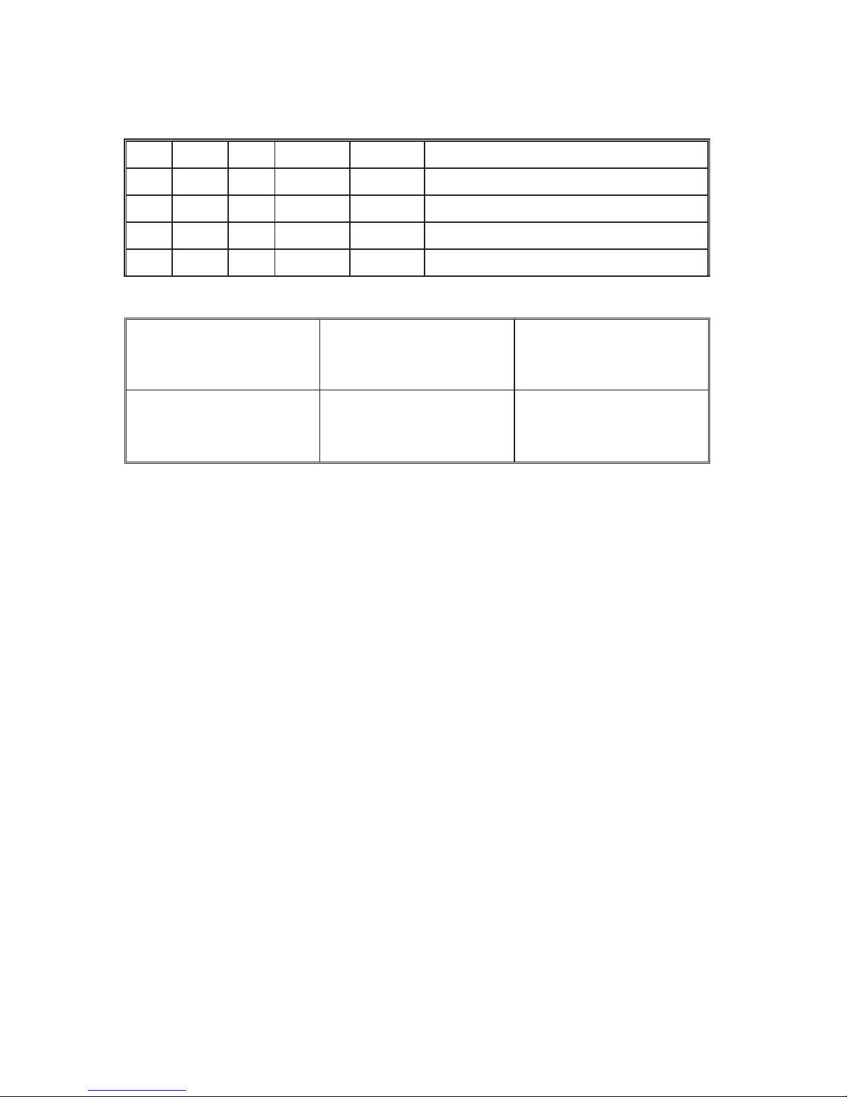
DPI 610/615 IS Portable Pressure Calibrator
Calibrator Version Indicator Version
Hydraulic Actuator Version
Page 8

ii
K249 Issue No. 4
WARNING
B
efore operating this instrument, read the safety instructions!
© General Electric Company. All rights reserved.
Page 9

iii
K249 Issue No. 4
EnglishEnglish
Page 10

iv
K249 Issue No. 4
Safety
The manufacturer has designed this equipment to be s
afe when operated using
the procedures detailed in this manual. Do not use this equipment for any other
purpose than that stated.
This publication contains operating and safety instructions that must be followed
to ensure safe operation and to maintain the equipment in a safe condition. The
safety instructions are either warnings or cautions issued to protect the user and
the equipment from injury or damage.
Use suitably qual ified * technicians and good engineering practice for all
procedures in this publication.
Pressure
Do not apply pressures greater than the safe working
pressure to the equipment.
Toxic Materials
There are no known toxic materials used in construction of this equipment .
Maintenance
The equipment must be maintained using the procedures in this publication.
Further manufacturers procedures should be carried out by authorized service
agents or the manufacturers service departments.
Approved Service Agents
www.gesensing.com
Technical Advice
For technical advice contact the manufacturer.
*
A qualif ied technician must have the necessary technical knowledge,
documentation, special test equipment and tools to carry out the required
work on this equipment .
This equipment meets the requirements of all relevant European
safety directives. The equipment carries the CE mark.
This symbol, on the instrument, indicates that the user should refer
to the user manual. This symbol, in this manual, indicates a
hazardous operation.
Page 11

v
K249 Issue No. 4
English
Specification
Pressure Ranges (Internal Transducers)
Safe working pressure
20 bar range 1.75 x full-scale
350 bar range 1.2 x full-scale
400 bar range 1.5 x full-scale
All other ranges 2 x full-scale
Accuracy
Combined non-linearity, hysteresis and repeatability
±
70 mbar range 0.05% F.S.
up to ±150 mbar 0.05% span
200 mbar to 20 bar (Calibrator): 0.025% F.S.
35 bar to 700 bar (Indicator): 0.025% F.S.
70 bar to 400 bar (Hydraulic) 0.025% F.S.
Temperature Effects
±0.004% of reading/°C (averaged over -10° to -40°C w.r.t. 20°C)
Electrical Parameters
Voltage Inputs
Range: ±30V
Accuracy ±0.05% rdg, ±0.004% F.S.
Resolution 100µV max
Current Inputs
Range: ±55mA
Accuracy ±0.05% rdg, ±0.004% F.S.
Resolution 1µA max
Current sink
Range: 24mA
A
ccuracy ±0.05% rdg, ±0.01% F.S.
Display
Size: 60 x 60 mm LCD Graphics
Reading ±99999, update rate 2 readings/sec
Environmental
Operating Temp.: -10°C to 50°C (Calibrated -10°C to 40°C)
Storage Temp: -20°C to 60°C
Calibration Temp: 21°C ±2°C
Sealing
Sealed to IP54
Physical
Size: 300 x 170 x 140 mm
Weight: 3 kg
Page 12

vi
K249 Issue No. 4
Introduction
G
eneral
Description of Procedures 1
Using the Guide 2
Summary of Functions
OPERATOR CONTROLS 3
DISPLAY 3
HARD KEY FUNCTIONS 4
SOFT KEYS 5
CURSOR KEYS 5
ELECTRICAL CONNECTIONS 6
Getting Started
Fitting Batteries 7
Switching On 7
Change Pressure Units 8
Voltage and Current Measurements 8
Typical Calibration Set-up (Pressure to Voltage) 9
Zero Display Reading 9
Task Selection
Task Key 10
Using TASK Functions 10
Set Units 10
Cal Mode 11
Basic Mode (Task Basic) 11
Taking Measurements
Pressure Transmitter (P-I) Task 12
Voltage Output Pressure Transmitter (P-V) Task 12
Pressure Converter (P-P) Task 13
Current to Pressure Converter (I-P) Task 14
Pressure Switch Test (P-Switch) Task 14
Pressure to Display (P-Display) Task 15
Leak Tests (Leak Test) Task 16
Transmitter Simulator (TX SIM) Task 17
Relief Valve Test (REL VALVE) Task 18
CONTENTS
C
ontd./
Page 13

vii
K249 Issue No. 4
English
Advanced Task
General 19
Select Input 19
Ambient Temperature Measurement 19
Process Functions 20
Tare Process Function 21
Min/Max Process Function 22
Filter Process Function 22
Flow Function 23
% Span 23
Select Output 24
Electrical Outputs (Loop Power) 24
mA Step 25
mA Ramp 26
mA Value 27
Task Set-up/Removal 28
Define New Task 28
Clear Task 28
Memory Operations
Saving Display (Snapshot) or Datalog 29
Store Operations (Screen Snapshots) 29
Recalling Stored Data (Screen Snapshots) 29
Datalog Operations 30
Auto Log (T imer) 30
Manual Logging 30
Recall Datalog Files 31
Uploading Datalog Files 32
Delete Datalog and Procedure Files 32
Downloading Procedure Files 33
Running Procedure Files 34
Recalling Data Files 35
CONTENTS (contd.)
Contd./
Page 14

vii i
K249 Issue No. 4
Using Set-up
G
eneral 36
Store Mode 36
Contrast 36
Settings - Select Set-up Option 36
Units 37
Def ine Special Units 37
Language 37
RS232 38
Powerdown 38
Calibration 38
Date and T ime (Real Time Clock) 39
Date Format 39
Set Date 39
Set T ime 39
Calibration
General 40
Calibration Check 40
Calibration Adjustment 40
General Procedures 41
Using The Calibration Menu 41
Temperature 42
Change PIN number 42
Add External Sensor 42
Hydraulic Calibrator Version
Introduction 45
Safety Instructions 46
Preparation for Use 46
Bleeding the System 47
Operation 48
Draining the Hydraulic Fluid 48
Flushing, Replenishing or Changing the Hydraulic Fluid 49
Appendix 1 - Datalog File Example
Typical Uploaded Datalog File (DPI 610 IS) 53
Typical Uploaded Datalog File (DPI 615 IS) 54
Appendix 2 - Baseefa Certificate of Conformity
EC-Type Examination Certificate AP2-1
CONTENTS (contd.)
Page 15

1
K249 Issue No. 4
English
General
The DPI 610 IS and DPI 615 IS intrinsically safe instruments measure and display
pneumatic and hydraulic pressure applied to the test port . Pressure
measurement can be absolute, gauge and sealed gauge and in ranges from 2.5
mbar to 700 bar.
Calibrator versions of this instrument contain pneumatic or hydraulic pressure
generation components to produce pneumatic pressure ranges between -1 to 20
bar and hydraulic pressure ranges up to 400 bar.
Using external electrical connections, the DPI 610 IS and DPI 615 IS intrinsically
safe instruments measure ±30 volts d.c. and ±55 mA. An integral sensor provides
measurement of ambient temperature. Additional sensors (option B1) connect to
an external connector and extend the pressure measurement range and include
differential pressure measurement. The DPI 615 instrument has an RS 232
connector to enable downloading of test data to a compatible documenting
system. Six alkaline C size batteries, IEC Type LR14, power the instrument .
Important Notice
Zinc-carbon and zinc-chloride cells must NOT be used in this instrument.
Use only the battery types as shown in the Table on page 7.
Description of Procedures
In the procedures outlined in this User Guide, hard
(fixed function) and soft
(variable function) key operations are shown in bold type (e.g.) TASK and F1. These
statements mean press the TASK key and press the F1 key. Soft key operations
can be allocated to both the F1 and F2 keys. Where a specific soft function is
referred to it is written in bold italics (e.g.) PROCESS.
This instrument has a number of operating modes which are described in
simplif ied form in the following sections. Diagrams accompanying the procedures
give typical selection sequences and shaded controls indicate that this control key
should be pressed in the appropriate sequence. Diagrams should be read from left
to right, top to bottom where appropriate. A shaded display soft box indicates
that the function key immediately below that soft box should be pressed (either F1
for the left hand soft box or F2 for the right).
In the above diagram the following key sequence is indicated.
(a) Press the F2 key (the key immediately below the UNITS soft box).
(b) Use the Up and Down cursor keys (only) to select the required
option. (If all keys shaded, use all these keys to select or enter data).
(c) Press the ENTER key.
INTRODUCTION Summary of Functions
Page 16

2
K249 Issue No. 4
INTRODUCTION Summary of Functions
Using This Guide
The following key symbols are used in the procedure diagrams which follow
Shaded cursor keys indicate that a combination of these
four keys, Up, Down, Left and Right should be used to (e.g.)
enter an alpha numeric value or to select a function.
Indicates the ENTER key. Used to confirm an operation or a
selection. Shading indicates key operation.
Exit key, used to clear current menu selection and return to
next menu level above current level. Used as an escape key
from current operation. Shading indicates key operation.
Hardkey (total 7). Legend beside key symbol indicates
function. Shading indicates key operation.
Maximum Instrument Ratings
The following table shows the maximum measurement input ratings of the
instrument which should not be exceeded.
PRESSURE 120% FULL SCALE
VOLTAGE 30 V d.c.
CURRENT 55 mA d.c.
Note 1: The display flashes if the input pressure, voltage or current overrange.
Note 2: Max applied voltage for external loop supply = 30V dc (see Page 8).
Page 17

3
K249 Issue No. 4
English
Figure 1 - DPI 610/615 Key-pad
DISPLAY
The display section of the instrument basically divides into four distinct sections.
The two main sections of the display are used to display a Measurand (input
parameter) and a Source (output paramet er). The remaining sections are used as a
status display area and to def ine soft key functions. A typical display is shown
below (e.g.),
OPERATOR CONTROLS (Figure 1)
These divide into two groups, the operator/display c
ontrols (shown in Figure 1) and
the pressure/vacuum generation components (shown in Figure 2). The operator
controls and a typical display, common to all instrument versions, is shown below.
INTRODUCTION Summary of Functions
Page 18

4
K249 Issue No. 4
HARD KEY FUNCTIONS (Fig. 1)
INTRODUCTION Summary of Functions
yeK noitcnuF egaPfeR
O/I
.FFOdnaNOtnemurtsniehtnrutotdesusiyeksihT
7
*PUTES
ehT PUTES noitarugifnoclarenegs’tnemurtsniehtotsseccasedivorpyek
.yrevilednosretemaraptluafedniatrecotputeserahcihwsretemarap
63
OREZ
ehT OREZ
rodnarusaemdetcelesehtrehtieorezotdesuebnacyek
otstpmettA.orezfo%5nihtiwsignidaeryalpsidehtfi,yalpsidecruos
,egassemrorrenanitlusertesfforegralaorez
,egralootoreZ
9
*TUPNI
ehT TUPNI .deyalpsidsidnarusaemhcihwtcelesotdesusiyek 91,81
KSAT
ehT KSAT tnemurtsniehtgnirugifnocyld
iparfosnaemasadesusiyek
eraerehT.noitarbilacecivedlanretxefosepyttnereffidforebmunarof
demmargorp-erperahcihwfonevele,elbaliavasnoitarugifnocksatytnewt
.elbanifedresueraenindna
01
*TUPTUO
ehT TUPTUO ecruoss’tne
murtsniehtfohcihwtcelesotdesusiyek
.deyalpsidsistuptuo
72-42
*EROTS
s’tnemurtsniehtwohnopugnidnepeD EROTS siyeksiht,putessiedom
ni(sneercsyalpsid02otpuerotsotrehtiedesu TOHSPANS otro,)edom
nineercsagolyllaunam GOLATAD .edom
63,92
*LLACER
.yalpsidehtotneercsderotsylsuoiverpallacerotdesusiyeksihT
ehtnognidnepeD EROTS sllaceryeksihtfonoitarepo,pu-tesedom
nI.elifgolatadroneercsderotsylsuoiverpafotohspansehtrehtoe
EROTS ehtgnisuyB.derotsneercstsalehtsyalpsidnoitceles,edom
hguorhtkcabrodrawrofrehtiellorcsnacrotarepoeht,syekrosruc
.snoitacolyromem
53,13,82
RETNE
ehT RETNE ni,ro,)atadderetnetpecca(atadretneotrehtiedesusiyek
.noitcelesnevigatpeccaot,syektfosehthtiwnoitcnujnoc
2
TIXE
ehT TIXE tfosdnadrahrehtoehtllahtiwnoitcnujnocnisetarepoyek
yletaidemmilevelehtot,levelunemroneercstnerrucehtmorftixeotsyek
sserp,levelunemynamorfyletelpmoctiuqoT.tignidecerp TIXE ehtlitnu
ECRUOS/ERUSAEM .deyalpsidsineercs
2
* These key functions are not available in BASIC mode
Page 19

5
K249 Issue No. 4
English
SOFT KEYS (Fig. 1)
Three soft keys, designated F1, EXIT and F2, are situated immediately below the
display as shown below. These keys have their function allocated by the
instrument software which is indicated in the bottom of the display (Voltage for F1
and Units for F2 in this example). They are used to select menu (program) options
and are fully described under the appropriate section headings.
CURSOR KEYS (Fig. 1)
The cursor keys consist of a block of four keys, arr
anged as shown in Figure 1.
They are designated Up , Down , Left and Right . In programs where
options need to be selected from a list , (e.g.) the TASK selection program, the Up
and Down cursor keys are used to highlight one of the options, from which it can
be selected by the ENTER key. In TASK mode, where more than one page of
options are provided, the Left and Right cursor keys will switch between
pages.
INTRODUCTION Summary of Functions
F
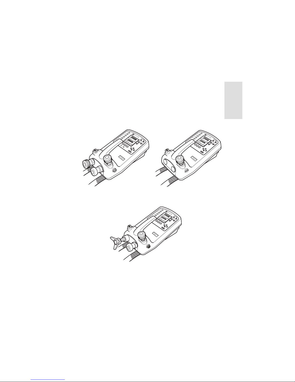
igure 2 - DPI 610/615 IS Calibrator Controls
Release Valve.
Releases system
pressure through vent
port. Use to gradually,
or completely reduce
pressure.
Vent Port
Select positive or
negative pressure
Cursor Keys
Soft Keys
F1, EXIT, F2
Electrical Inputs,
V,I, Switch
and mA sink
External Interfaces under flap
Power, RS232, External Transducer
Pump, pressurises
test port and
internal sensor.
Use to approximately
set output pressure.
Fine pressure adjustment.
Start with control screwed
out half-way to allow
fine adjustment
up or down.
Test port.
Connect to unit under test.
G1/8" coupling.
Use a sealing washer.
Hard keys
5
Page 20

6
K249 Issue No. 4
ELECTRICAL CONNECTIONS
Figure 3 - Electrical System Connections
Measurement
inputs and Source Outputs are made via the control panel sockets as
shown below.
Figure 4 - Electrical Measurement Inputs/Source Outp
uts
INTRODUCTION Summary of Functions
PRESSURE INT
bar
VOLTAGE V
F2F1
Electrical
Measurement
Input Sockets
CURRENT
UNITS
INPUTS
OUTPUTS
Output Window
Input Window
PRESSURE
max 30V
CATII
TASK:BASIC
DPI 615 IS
Page 21

7
K249 Issue No. 4
English
The first time that the instrument is powered up, it will power-up in BASIC mode
with the main screen displaying voltage in the measurand display area and
pressure in the source display area. To switch to Current as measurand, press F1
as shown. Similarly, F1 to return to Voltage.
Note: No other keys are active in this mode and the instrument can only be
reconf igured by pressing the TASK key and selecting another mode.
Fitting Batteries
G
etting Started
WARNING: BATTERIES MUST ONLY BE FITTED IN A SAFE AREA.
USE ONLY THE BATTERIES SPECIFIED IN THE TABLE.
Caution: Old batteries can leak and cause corrosion. Never leave
discharged batteries in the instrument. Old batteries should be treated
as hazardous waste and disposed of accordingly.
Switching On
Press the I
/O switch on the front panel and proceed as follows.
rerutcafunaM .oNepyT
rezigrenE 39NEepyTlairtsudnI
rezigrenE 2MA.C.41RL.39E
llecaruD 41RL-0041NM
atraV
epyT4104.oN
2MA.C.41RL
llecorP 41RL-0041NM
Page 22

8
K249 Issue No. 4
Change Pressure Units
To change the pressure units proceed as follows. If
the four units displayed are
not the units required, press TASK and select any task, other than BASIC, press
SETUP and proceed as detailed on page 36. To return to BASIC mode, press TASK
and select BASIC.
In BASIC mode, the unit is configured to carry out basic Pressure to Voltage (P to V)
or Pressure to Current (P to I) tests, a typical test procedure follows.
Voltage and Current Measurements
Connect the electrical input sockets as follows for
voltage and current
measurements. Use the test leads provided and DO NOT push bare wires into the
sockets.
Note: Maximum applied voltage = 30V dc,. Maximum input current = 55mA dc
Getting Started
Note: Maximum applied voltage for external loop supply = 30V dc
Page 23

9
K249 Issue No. 4
English
PRESSURE INT
bar
VOLTAGE
F2F1
V
P
V
-+
CURRENT
PRESSURE
UNITS
Ext Press. Source
(Indicator Only)
Pressure
Regulator
Max30V
CATII
-
+
+
-
BARRIER
SAFE
SAFE
EXT
SUPPL
Y
TASK:BASIC
DPI 615 IS
Typical Calibration Setup (Pressure to Voltage)
Connect a device under test to the instrument as shown below.
General Procedure
Use the hand-pump to pressurise the system to the re
quired level as
indicated on the display. Allow the display to settle and screw the volume
adjuster in or out as a fine adjustment to the required pressure. Record the
measurand (e.g.) Voltage, reading at each applied pressure.
Zero Display Reading
Both the input and output windows can be set to zero by operation of the ZERO
key, providing that the displayed reading is already within 5% of zero. To zero
either the INPUT (Measurand) or OUTPUT (Source) windows, proceed as follows
(e.g.),
Getting Started
Page 24

10
K249 Issue No. 4
Task Selection
Task Key
The TASK key is used to set up the instrument for a
number of specif ic types of
test . There are two modes BASIC and ADVANCED and nine other specif ic types of
test which automatically configure the instrument on selection from the TASK
menu. The tasks available under the TASK menu are held on three pages shown
below. To select a task from the menu, press the TASK key, position the cursor over
the desired task and press the ENTER key as shown below. Use the right/left cursor
keys to switch between pages.
Using TASK Functions
Specific tasks are selected as shown above. The following diagrams show how to
connect the unit under test (UUT) for each task selectable under the TASK menu.
Input and Output units, where applicable can be selected by pressing either the
INPUT or OUTPUT keys as shown below.
Set Units
Note: I
f the four units displayed are not the units required, press SETUP, select
SETTINGS and refer to Page 36.
Page 25

11
K249 Issue No. 4
English
Cal Mode (DPI 615 versions only)
Cal mode, which is available in tasks P-I, P-P, P-V, P-P, P-DISPLAY and P-SWITCH,
provides a method of setting up test parameters manually. Downloaded test
procedures can also automatically set up and turn on the Cal Mode function. The
method of turning on and setting up Cal Mode is shown below for a P-I task. The
method is similar for all the other tasks to which Cal Mode applies.
Pressing the F1 key (TURN ON CAL MODE), provides the set-up screen for the CAL
mode. Initially, the cursor is placed in the UUT SPAN field to allow the required
span range to be entered. The corresponding values for the UUT output
parameter (current) are then set, followed by the maximum error value and error
type (%rdg or %Span). When all test parameters have been set-up, the screen
changes to display the input and output and the test results. The test result can
only be displayed to within a range of ±9.99%. If the test result is outside this
range, either the left pointing (-ve error) or right pointing (+ve error) chevrons are
displayed. W ithin this error band, the actual tolerance value is displayed. Test
results can either be stored as snapshots or logged as datalog f iles, depending
upon how the instrument has been set-up.
Basic Mode (Task BASIC)
This instrument will power-up in this mode the first
time that it is used. To select BASIC
from any other task, press the TASK key and select BASIC and press the ENTER key.
BASIC mode is fully described in the Getting Started, section (see page 7).
Task Selection
Page 26

12
K249 Issue No. 4
Pressure Transmitter (P-I) Task
Select the P-I task from the task menu and connect t
he Unit Under Test (UUT) to
the calibrator as shown below.
Taking Measurements
If required, select the output units as described o
n page 10.
If applicable, turn on Cal Mode and set-up test parameters as detailed on
page 11.
Voltage Output Pressure Transmitter (P-V) Task
Select the P-V task from the task menu and connect the Unit Under Test (UUT) to
the calibrator as shown below.
P
I
Ext Press. Source
(Indicator Only)
Pressure
Regulator
PRESSUREINT bar
CURRENT mA
F2F1
+
+
-
BARRIER
SAFE
SAFE
EXT
SUPPLY
max30V
TASK: P-I
SNAPSHOTMODE
DPI 615 IS
If required, select the output units as described on page 10.
If applicable, turn on Cal Mode and set-up test parameters as detailed on
page 11.
PRESSURE INT
bar
VOLTAGE
F2F1
V
P
V
-+
CURRENT
PRESSURE
UNITS
Ext Press. Source
(Indicator Only)
Pressure
Regulator
Max30V
CATII
-
+
+
-
BARRIER
SAFE
SAFE
EXT
SUPPLY
TASK:BASIC
DPI 615 IS
Page 27

13
K249 Issue No. 4
English
Taking Measurements
Pressure Converter (Pressure to Pressure) Task
Select the P-P task from the task menu and connect the Unit Under Test (UUT) to
the calibrator as shown below. Testing a converter requires one pressure to be
applied to the unit under test (UUT) and another (converter output) to be
measured. The additional measurement is provided by the external transducer
option.
Method
Connect the UUT to the calibrator as shown below an
d plug the external
transducer into the calibrator as shown below.
USERS2 32
INSAFE
AREAONLY
Press the TASK key and select the P-P task. Providing the external
transducer has been calibrated and its parameters stored in the
instrument , the display will show External pressure in the input window
and calibrator Output pressure in the output window. If an error message
NO SENSOR OR CAL INVALID is displayed, this indicates that the external
transducer has not been entered and/or calibrated with the instrument.
Refer to Page 42 for details of adding an external transducer. If an external
transducer change is made, switch the calibrator off and then on to load
new transducer data.
If required, select the input and output units as described on page 10.
If applicable, turn on Cal Mode and set-up test parameters as detailed on
page 11.
Page 28

14
K249 Issue No. 4
P
I
-
PRESSUREINT
bar
F2F1
External
Pressure
Supply
OUTPUT
NEW VALUE
CURRENT mA
OK
+
+
-
-
BARRIER
SAFE
SAFE
EXT
SUPPLY
max30V
TASK: I-P
SNAPSHOTMODE
DPI 615 IS
Current to Pressure Converter (I-P) Task
Taking Measurements
Use the U
p and Down cursor keys to adjust the loop current to the
required value. Alternatively, press ENTER and use cursor keys to enter a
finite value. Cursor keys can then be used to nudge the output either up or
down.
If required, change pressure units with INPUT key. A flashing CHECK LOOP
message indicates either an open circuit supply loop (or no external
supply).
Pressure Switch Test (P-SWITCH) Task
Contact state will be shown on display. When conta
cts close, buzzer sounds.
To run switch test, close vent valve and press the RUN (F1) key.
Using the handpump, increase the appl ied pressure to just below the
switch operating point. Screw the volume adjuster in until the switch
operates (the operating pressure of the switch is then written to the
display).
Reduce pressure until the switch releases (indicated by the switch symbol).
The release pressure is then written to the display and the hysteresis
displayed.
PRESSUREINT
bar
F2F1
External Pressure Source
(Indicator Only)
Pressure
Regulator
RUN
CONTACTSTATE
max30V
TASK: P-SWITCH
SNAPSHOTMODE
DPI 615 IS
Page 29

15
K249 Issue No. 4
English
External Pressure Source
(Indicator Only)
Pressure
Regulator
TEST UNIT
(Dial Gauge)
PRESSURE INT bar
F2F1
DISPLAY
CHANGE
VALUE
TASK: P-DISPLAY
SNAPSHOT MODE
max30V
DPI 615 IS
Taking Measurements
Pressure to Display (P-DISPLAY) Task
P-Display is a special application of Datalog. To use this mode, select Datalog
from the Store Mode menu as detailed on Page 36. Connect the device under test
to the instrument as shown below and, if required, turn on and set-up Cal Mode
(see page 11).
After logging final test point, terminate as follows (e.g.),
Press TASK and select P-DISPLAY. If required, use OUTPUT key to change
pressure units.
Set-up a datalog file as detailed on Page 30.
Note: TRIGGER f ield, automatically set to KEYPRESS, cannot be changed.
Apply a series of test pressures to the device under test. Enter displayed
reading at each pressure and log each point (e.g.),
Page 30

16
K249 Issue No. 4
Leak Test (LEAK TEST) Task
Taking Measurements
Close the vent valve and pressurise the external system to the required
LEAK TEST pressure.
Press the RUN (F2) key to start the leak test. When completed, the bleeper
sounds and the leak test results are written to the display.
If required, use the INPUT key to change pressure units.
Set-up the leak test WAIT and DURATION times to the required values as
shown below. A minimum wait period of 3 minutes is recommended.
External Pressure Source
(Indicator Only)
Pressure
Regulator
EXTERNAL
SYSTEM
PRESSURE INT bar
F2F1
RUN
CHANGE
VALUE
WAIT
DURATION
STARTPRESS
STOP PRESS
PRESS CHANGE
LEAK RATE
secs
secs
bar
bar
bar
bar/m
60
60
max30V
TASK: LEAK TEST
SNAPSHOT MODE
DPI 615 IS
Page 31

17
K249 Issue No. 4
English
On completion of Tx SIM set-up, the display is configured as follows (e.g.).
Connect an external power source to the output loop as detailed on Page 24.
To subsequently change any of the Tx SIM scaling parameters, press CHANGE
VALUE key (F1) to obtain the TX Simulation set-up display.
To change the pressure units, press INPUT and select the required scale units. If
the required scale units are not listed, press SETUP, select SET TINGS and proceed
as detailed on Page 37.
Taking Measurements
T
ransmitter Simulator (TX SIM) Task
When used with an external voltage source (see Page 24), provides a current
output proportional to the calibrators measured output pressure (indicated
pressure on indicator only version). Select task TX SIM. Press EXIT to skip set-up
screen if parameters are correct.
Page 32

18
K249 Issue No. 4
To change the pressure units, if required, press I
NPUT and select the
required units using the cursor keys.
Close the vent valve and, using the hand-pump or external pressure
supply, apply pressure to the relief valve under test .
When the relief valve operates, the maximum recorded pressure indicates
the operating point of the valve.
Record the test results.
Note: The STORE key can be used for this purpose. Use right cursor key
initially, followed by up/down keys to enter Snapshot text.
Open vent valve to release test pressure.
Note: If using external pressure supply, isolate supply before opening the
vent valve.
Taking Measurements
R
elief Valve Test (REL VALVE) Task
To carry out a relief valve test , press TASK and select REL VALVE. Connect the
output pressure port of the instrument to an external system as shown below.
PRESSURE INT
bar
bar
RESET
MAXIMUM
MINIMUM
MAX/MIN
F2F1
External Pressure Source
(Indicator Only)
Pressure
Regulator
PRESSURE INT
max30V
TASK: RELVALVE
SNAPSHOT MODE
DPI 615 IS
Page 33

19
K249 Issue No. 4
English
General
Advanced task allows the user to configure the instrument to monitor one of a
number of different input measurands (Inputs) and outputs (Sources).
Additionally, five process functions, Tare, Max/Min, Filter, Flow and % Span can
be applied to the input functions.
Select Input
To select an input channel for display, select A
DVANCED Task from the task menu
and proceed as follows. If, in addition to process functions, a range of units is
available for the selected channel, a UNITS soft box (actioned by the F2 function
key), will be written to the display.
The following procedure shows the method of input channel selection and the
method of changing units (e.g.),
Note: Left/right arrow keys function as page up/down keys .
Refer to pages 20 to 23 for details of process functions.
Ambient Temperature Measurement
To set-up the instrument to read ambient temperature
, proceed as follows (e.g.),
Note: Ensure that the temperature reading has stabilised.
Advanced Task S
elect Input
Page 34

20
K249 Issue No. 4
Process Functions
If required, the following process functions are available on the Measurand (INPUT)
display but only in ADVANCED task. If the instrument is in any other mode i.e.
BASIC or any other task mode, the input and output displays must first be
configured in ADVANCED task.
Note: PROCESS functions are not available to the output (SOURCE) channel.
A summary of the process functions follows.
Tare Allows either the current display value or a manually
entered value to be tared off display parameter
reading.
Max/Min Displays running Max/Min and Present display values
simultaneously. Resettable via F1 key.
Filter Applies low pass f ilter function to displayed
parameter. Filter characteristics (Settling time and
Band) are user programmable.
Flow Applies square root function to displayed parameter.
% Span Converts displayed parameter reading to a
percentage of span. Span definable via the F1 key.
Following selection of ADVANCED from the task menu, press the INPUT key. Use
the Up
or Down cursor keys to select the required input. Press the PROCESS
(F1) key and use the Left or Right cursor keys to enable the process on/off
(e.g.),
Press ENTER to switch the process ON with existing settings or F1 to change
process settings (where applicable).
Advanced Task Process Functions
 Loading...