

Page 1
GE Consumer Products
TECHNICAL SERVICE GUIDE
Profile Gas and
Electric Dryers
A
C
B
K
M
O
E
H
C
Y
C
Y
L
M
E
L
P
H
E
A
R
T
S
T
O
T
P
S
W
E
O
R
P
MODEL SERIES:
DPGT750EC/GC
PUB # 31-9104 07/03
Page 2

IMPORTANT SAFETY NOTICE
The information in this service guide is intended for use by
individuals possessing adequate backgrounds of electrical,
electronic, and mechanical experience. Any attempt to rep air a
major appliance may result in personal injury and property
damage. The manufacturer or seller cannot be responsible for the
interpretation of this information, nor can it assume any liability in
connection with its use.
WARNING
If the information in this manual is not followed exactly , fire or explosion
may result causing property damage, personal injury or death. If you smell
gas:
– Do not try to light any appliance.
– Do not touch any electrical switch; do not use any phone in the
building.
– Immediately call the gas supplier from a neighbor’s phone. Follow
the gas supplier’s instructions.
– If you cannot reach the gas supplier, call the fire dep artment.
WARNING
To avoid personal injury, disconnect power before servicing this product. If
electrical power is required for diagnosis or test purposes, disconnect the
power immediately after performing the necessary checks.
RECONNECT ALL GROUNDING DEVICES
If grounding wires, screws, straps, clips, nuts, or washers used to
complete a path to ground are removed for service, they must be returned
to their original position and properly fastened.
GE Consumer Products
Technical Service Guide
Copyright © 2003
All rights reserved. This service guide may not be reproduced in whole or in part in any
form without written permission from the General Electric Company .
– 2 –
Page 3

Table of Contents
Airflow Diagram (Gas and Electric Models)....................................................................................15
Backsplash ...................................................................................................................................20
Belt Switch....................................................................................................................................26
Blower Motor .................................................................................................................................27
Component Locator Views.............................................................................................................16
Consumer Help Screens................................................................................................................13
Control Features............................................................................................................................. 7
Control Quick Reference Chart ......................................................................................................38
Control System .............................................................................................................................20
Door Switch...................................................................................................................................25
Drive Belt.......................................................................................................................................26
Drive Motor ....................................................................................................................................27
Drum .............................................................................................................................................24
Drum Light ....................................................................................................................................26
Drum Rollers .................................................................................................................................25
Dry Cycles ..................................................................................................................................... 9
Dryer Components ........................................................................................................................20
Dryer Control Panel ........................................................................................................................ 7
Dryer T emperature Settings (Gas and Electric)..............................................................................15
Error Charts............................................................................................................................... ....43
Factory T est Mode ........................................................................................................................36
Field Service Mode........................................................................................................................35
Front Panel ...................................................................................................................................23
Gas V alve......................................................................................................................................32
Heater Assembly (Electric Models) ...............................................................................................29
Hi-Limit Thermostat .......................................................................................................................32
Ignitor ............................................................................................................................................33
Ignitor and Flame Detector ............................................................................................................34
Inlet Safety Thermostat .................................................................................................................30
Inlet Thermistor .............................................................................................................................30
Inverter ..........................................................................................................................................21
Inverter and Main Board Pin Connectors ........................................................................................18
Main Control Board and T ouch Screen LCD...................................................................................20
Membrane Keypanel .....................................................................................................................21
Moisture Sensor............................................................................................................................34
My Cycles.....................................................................................................................................12
Nomenclature ................................................................................................................................. 4
Operation Overview ........................................................................................................................15
Outlet Thermistor ..........................................................................................................................31
Outlet Thermostat .........................................................................................................................31
Overview ......................................................................................................................................... 6
Parts ............................................................................................................................................. 48
Quick Start..................................................................................................................................... 8
Reversing the Door Swing..............................................................................................................58
Sales Demo Mode.........................................................................................................................14
Schematics...................................................................................................................................46
Signal (Beeper) .............................................................................................................................22
Summary Screen ..........................................................................................................................10
Switching the Washer and Dryer Backsplashes ............................................................................60
T op Cover ......................................................................................................................................23
Troubleshooting .............................................................................................................................39
Troubleshooting Charts..................................................................................................................40
Warranty ........................................................................................................................................ 5
– 3 –
Page 4
Nomenclature
D P G T 7 5 0 E C 0 W W
GE Dryer
Feature Pack
Common Brand Features
Exceptions:
H = Energy Star
P = Profile™
K, N = Special
S = Spacemaker®
Capacity/Configuration
L = Large S = Super
X = Extra-Large K = Compact
G = Giant
Control Platform
B = Buttons (Touch Pad) T = Touch Screen
Q = QuickClean S = Stationary
R = Rotary F = Fabric Care
P = Portable H = Horizontal Axis
Drying Machine
Backsplash
Color
Body Color
Model Year
Designator
Engineering
Revision
Fuel/Voltage
E = Electric
G = Gas
Dryer Control
Number of Cycles
Heat Selections
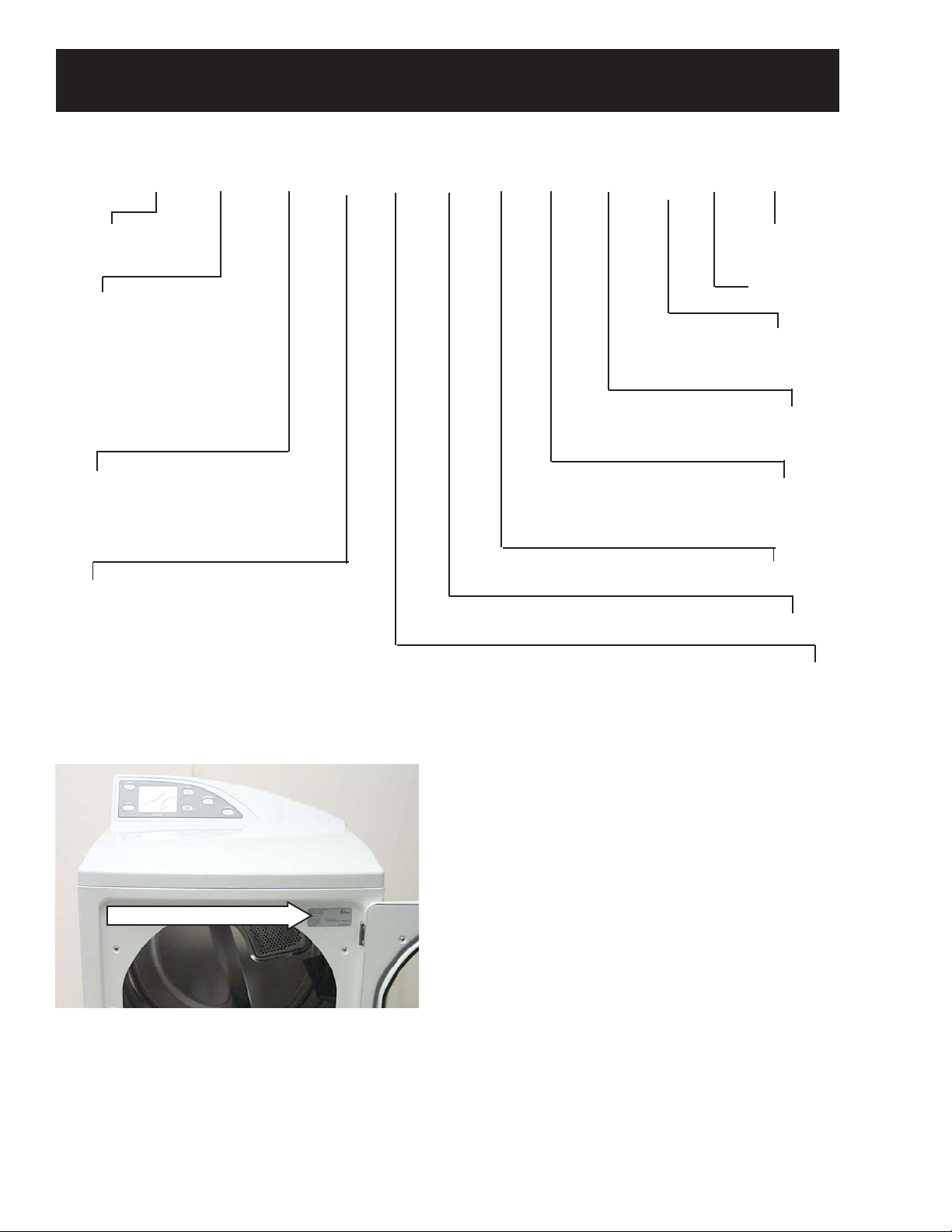
Model & Serial Numbers
Note: Model number and serial number are
located on the front panel inside the door .
• The technical sheet is located behind
the control panel.
Serial Number
The first two characters of the serial number
identify the month and year of manufacture.
Example: RF123456S = August 2003
A - JA N 2005 - H
D - FEB 2004 - G
F - MAR 2003 - F
G - APR 2002 - D
The letter
designating the
year repeats every
12 years.
H - MA Y 2001 - A
L - JUN 2000 - Z
M - JUL 1999 - V
R - AUG 1998 - T
S - SEP 1997 - S
Example:
T - 1974
T - 1986
T - 1998
T - OCT 1996 - R
V - NOV 1995 - M
Z - DEC 1994 - L
– 4 –
Page 5
For The Period Of: We Will Replace:
One Year Any part of the dryer which fails due to a defect in materials or workmanship. During this
From the date of the full one-year warranty, GE will also provide, free of charge, all labor and related service costs to
original purchase replace the defective part.
Second Year Any part of the dryer which fails due to a defect in materials or workmanship. During this
From the date of the additional one-year limited warranty, you will be responsible for any labor or related service costs.
original purchase
Third through Fifth Year The extra-large or super-capacity dryer drum and main electronic control board if any of these parts should
From the date of the fail due to a defect in materials or workmanship. During this additional three-year limited warranty,
original purchase you will be responsible for any labor or related service costs.
A
ll warranty service provided by our Factory Service Centers or
an authorized Customer Care
®
technician. To schedule service
on-line, 24 hours a day, visit us at www.GEAppliances.com or
call 800.GE.CARES (800.432.2737).
■ Service trips to your home to teach you how to use
the product.
■ Improper installation, delivery or maintenance.
■ Failure of the product if it is abused, misused, or
used for other than the intended purpose or used
commercially.
■ Replacement of the light bulb after its expected
useful life.
■ Replacement of house fuses or resetting of circuit
breakers.
■ Damage to the product caused by accident, fire, floods
or acts of God.
■ Incidental or consequential damage caused by possible
defects with this appliance.
■ Damage caused after delivery.
What Is Not Covered:
This warranty is extended to the original purchaser and any succeeding owner for products purchased for home use within the
USA. In Alaska, the warranty excludes the cost of shipping or service calls to your home. Proof of the original purchase date is
needed to obtain service under the warranty.
Some states do not allow the exclusion or limitation of incidental or consequential damages. This warranty gives you specific
legal rights, and you may also have other rights which vary from state to state. To know what your legal rights are, consult
your local or state consumer affairs office or your state’s Attorney General.
Warrantor: General Electric Company. Louisville, KY 40225
Warranty
Note: The LCD screen is part of the main electronic board and under the 5 year part warranty. The
inverter board is covered by a 2 year part warranty.
– 5 –
Page 6
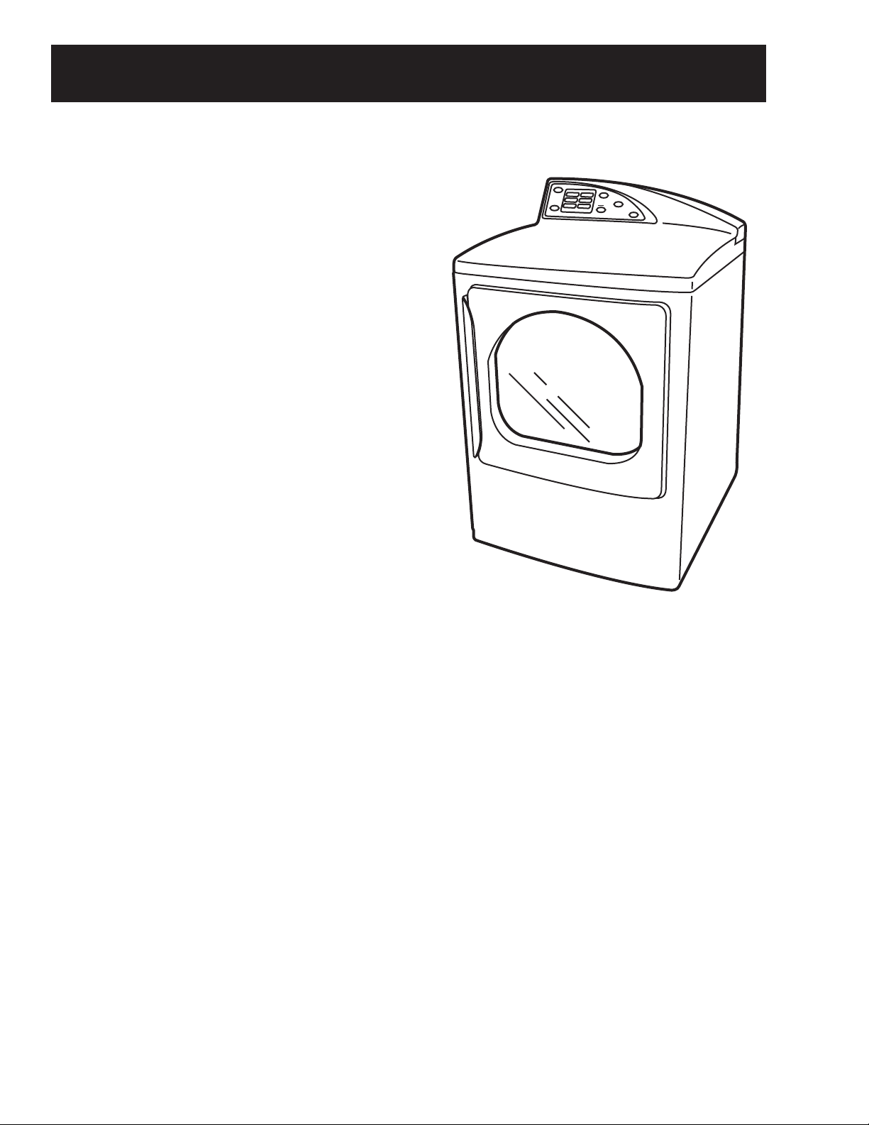
Overview
General
The GE Profile Harmony Dryer is part of the GE Profile
Harmony Clothes Care System utilizing the latest
developments in dryer technology .
Most conventional drying systems have a single motor
that powers both the blower and the drum. Therefore,
the blower fan and dryer drum are powered at the same
rate of speed. If air flow is impeded by lint buildup or
lengthy venting, the dryer cannot increase the fan
speed without increasing the drum speed. The
Harmony Dryer System utilizes dual motors and
strategically placed sensors. This enables the dryer to
respond quickly to temperature changes and ensure
proper air flow to optimize drying effectiveness.
Other features include:
A
C
B
K
E
L
P
H
M
O
E
H
C
Y
C
Y
L
M
E
A
R
T
S
T
O
T
P
S
W
E
O
R
P
Communication Link to the Washer- The dryer uses a
serial cable to automatically receive information from
the washer about the nature of the wash load,
essentially presetting the dryer controls so the user
doesn’t have to.
Dual Motors - The dryer is equipped with dual motors one dedicated to the drum, the other to the blower fan.
The addition of a dedicated blower motor enables the dryer to alter fan speed whenever necessary to
optimize air flow. This capability greatly increases drying performance and efficiency. (See
and Blower Motor).
Drive Motor
V ariable Heater - The dryer's heater is capable of variable heat output. It s voltage regulation feature
allows the system to be rated at 6000 watts.
Dual Thermistors - Thermistors are much more sensitive to temperature changes and can relay the
information faster than thermostats. The dryer uses dual thermistors to monitor incoming air
temperature as well as the air temperature leaving the drum. The sensors work together with the
variable heater and blower to provide consistent even heat. (See
Inlet Thermistor.)
Moisture Sensor - The moisture sensor allows the control to monitor the fabric for moisture content and
end the cycle at the desired moisture level. (See
Moisture Sensor.)
Plastic Top & Backsplash - The dryer top and backsplash have UV stabilizers to prevent yellowing when
exposed to sunlight.
– 6 –
Page 7
P
O
W
E
R
M
Y
C
Y
C
L
E
S
B
A
C
K
H
E
L
P
S
TART
S
TOP
H
O
M
E
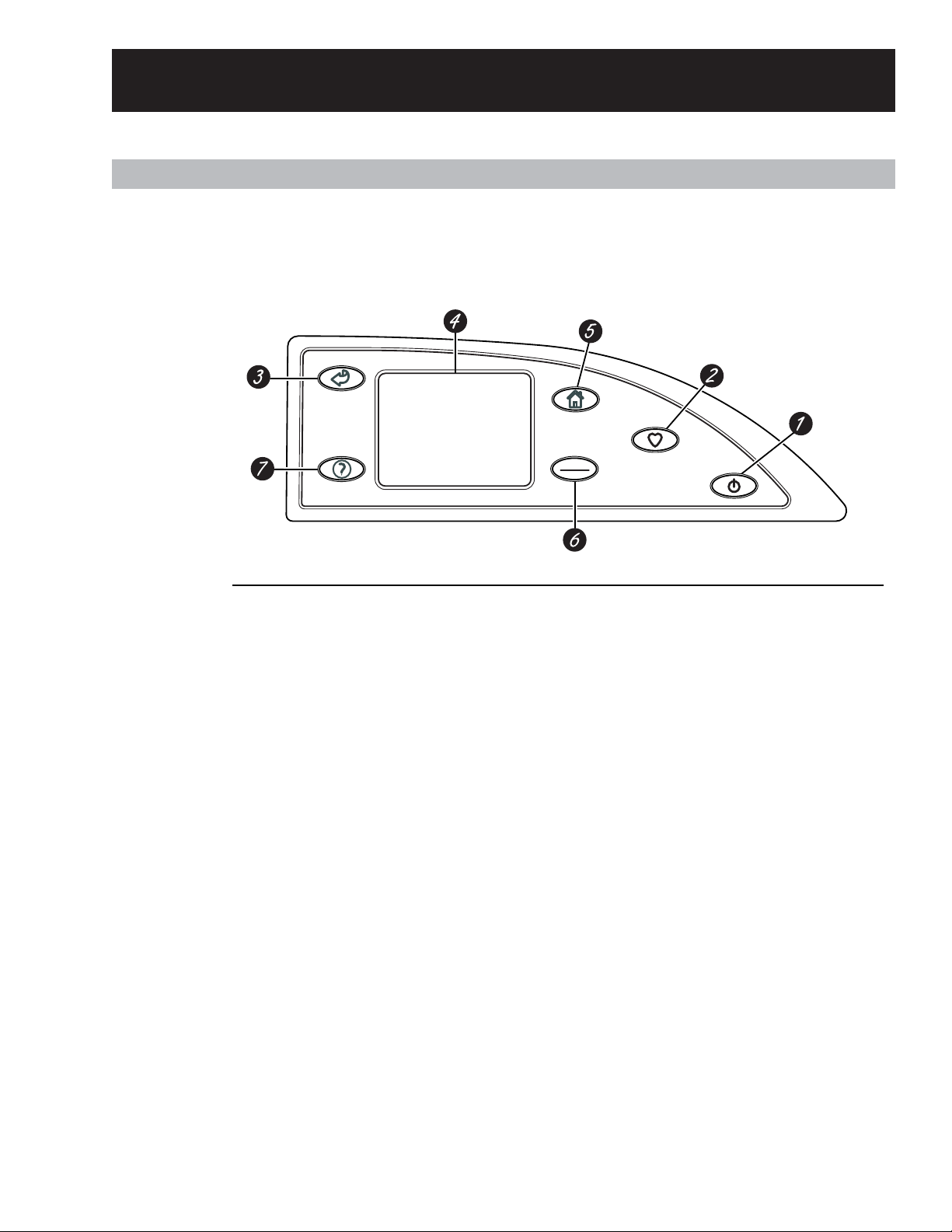
Features of
the dryer
control
panel
1 POWER. Press to “wake up” the display. If
the display is active, press to put the dryer
into standby mode. You may also press the
Touch Screen or any button to “wake up”
the display.
NOTE: Pressing POWER does not
disconnect the appliance from the power
supply.
2 MY CYCLES. Press to use, create, rename,
modify or delete custom dry cycles.
3 BACK. Press to return to the previous
screen.
4 TOUCH SCREEN. Press the graphics
on the interactive display to use the dryer
features.
Do not use sharp objects to press the Touch
Screen.
NOTE: If the dryer is inactive for 5
minutes, the Touch Screen will go into
standby mode, and the display will be dark.
Press the Touch Screen or any button to
“wake up” the display.
5 HOME. Press to return to the “TOUCH TO
SELECT Sensor DRY CYCLE” screen (Home
Screen).
6 START/STOP. Press to start a dry cycle.
If the dryer is running, pressing once will
pause the dryer. Press again to restart the
dry cycle.
NOTE: If the dryer is paused and the cycle
is not restarted within five minutes, the
dryer will enter standby mode and the
current dry cycle will be canceled.
7 HELP. Press to set machine preferences, to
find help using the Touch Screen or to find
troubleshooting tips for common dryer
problems.
Throughout this manual, features and appearance may vary from your model.
Control Features
Dryer Control Panel
– 7 –
Page 8
Quick Start
Getting
Started
If the Touch
Screen is
dark, press
POWER or
the Touch
Screen to
access the
dry cycles
menu.
Clean the lint filter.
IMPORTANT: Clean the lint filter each time
you use the dryer.
Add clothes. Do not overload. This wastes
energy and promotes wrinkling.
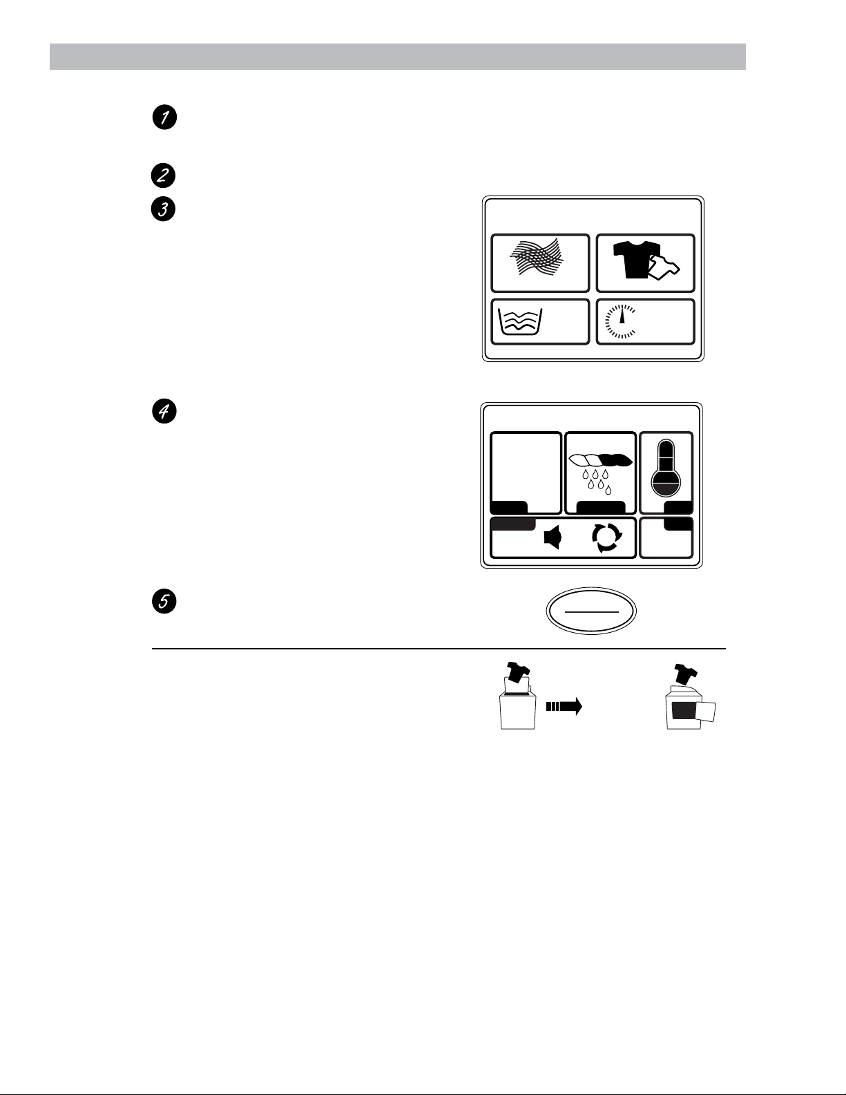
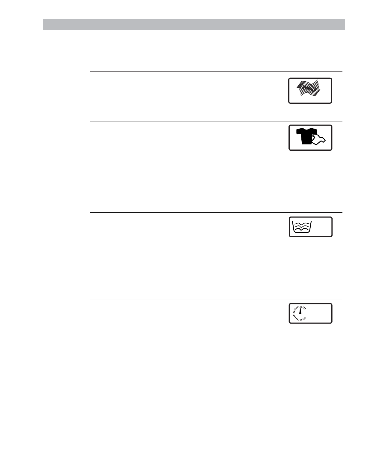
Select one of the four drying methods from the
Home Screen:
• Press BY FABRIC to dry according to fabric
type.
• Press BY GARMENT to dry according to
clothing type.
• Press SPECIAL CYCLES to dry nongarment
items, to dry without heat or to dry using the
drying rack.
• Press TIMED DRY to specify a drying time
and temperature.
Change any of the automatic settings, if
desired, by pressing the Touch Screen and
following the on-screen instructions.
By changing the settings you can:
• Change the level of dryness
• Change the drying temperature
• Set a Delay Start or Extended Tumble, or
change the End-of-Cycle Signal volume
• Adjust time settings
TOUCH TO SELECT
Sensor
BY
FABRIC
SUMMARY SCREEN
COTTONS MORE DRY
SPECIAL
CYCLES
Home Screen
DRY CYCLE
BY
GARMENT
TIMED DRY
0:36
TEMPDRYNESSCYCLE
TIMEOPTIONS
Washer
Communicated
Cycles
Close the door and press START.
The dryer will not operate unless the door is
closed.
If the Washer/Dryer Communication features
of your washer and dryer are turned ON, your
dryer will receive cycle information from your
washer to create a dry cycle that matches your
wash load.
After the wash cycle is complete,
communication begins once either the washer
or dryer Touch Screen is activated.
Once the information is received, your dryer
can then create the optimal dry cycle for your
load. You can then change any of the
automatic cycles, as desired.
NOTE: For some communicated wash cycles,
your dryer will prompt you to select a FABRIC
TYPE.
See “Final Setup” in the Installation
Instructions for attaching the serial cable for
Washer/Dryer Communication.
S
TART
S
TOP
SENDING INFO TO DRYER... RECEIVING...
Washer Display Dryer Display
– 8 –
Page 9
Dry Cycles
Drying by
Fabric Type
If the Touch Screen is dark, press POWER or the Touch Screen to access the dry cycles menu.
The default cycle settings are based on standard load types. Always follow the fabric manufacturer’s
care label when laundering.
• Blends
• Cottons
• Delicates
• Knits
• Polyester
• Silks (Washable)
BY
FABRIC
Drying by
Garment
Type
• Athletic Wear
• Blouses
• Delicates
• Dress Shirts
• Easy Care
• Everyday
Wear/Casual
• Jackets/Coats
• Jeans
• Khakis
• Knits
• Lingerie
• Mixed Garments
• Play Clothes
• Silks (Washable)
• Sweaters
• Swimwear
• Underwear
BY
GARMENT
Select By FABRIC to dry loads sorted by fabric type.
FABRIC CYCLES include:
Select By Garment to dry loads sorted by garment type.
GARMENT CYCLES include:
Drying
Using
Timed Dry
1 Press TIMED DRY.
2 Use the arrows to set more or less time; then press OK.
3 Use the arrows to set the temperature; then press OK.
4 Press START.
TIMED DRY
Select TIMED DRY to set your own drying time.
Timed Dry is also recommended for small loads.
Drying
Using the
Special
Cycles
• Air Dry
• Blankets (Cotton)
• Blankets (Other)
• Comforter
• Dewrinkle
• Dryel
™
• Pet Bedding
(Washable)
• Pillows (Washable)
• Rack Dry
• Sheets
• Sneakers
• Throw Rugs
(Washable)
• Towels
• Warm Up
SPECIAL
CYCLES
Select SPECIAL CYCLES to dry loads of nongarment items, use the
drying rack or to tumble using low or no heat.
SPECIAL CYCLES include:
– 9 –
Page 10
Summary Screen
About the
Summary
Screen
After selecting a dry cycle, the Summary Screen
displays the automatic settings for the cycle you
have chosen. You can adjust these by touching
the screen location for any of the settings
shown.
If you change any of the automatic settings,
you can save the new settings as a custom
“My Cycle” by pressing the MY CYCLES button
while on the Summary Screen and choosing
SAVE CURRENT SETTINGS.
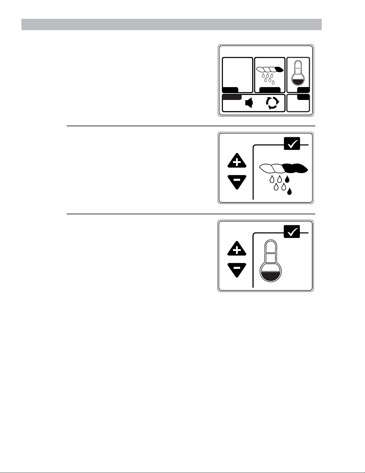
Changing
the Dryness
Level
To change the dryness level, touch the
DRYNESS pad on the Touch Screen; then use
the arrows to select the level of dryness. Press
OK when you have reached the desired setting.
MORE DRY – Use for heavy-duty fabrics.
DRY – Use for a normal dryness level suitable
for most loads. This is the preferred cycle for
energy saving.
LESS DRY – Use for lighter fabrics.
DAMP – Use to leave items partially damp.
Changing
the Drying
Temperature
To change the drying temperature, touch
the TEMP pad on the Touch Screen; then
use the arrows to select higher or lower
temperature. Press OK when you have
reached the desired setting.
HIGH – For regular to heavy cottons.
MEDIUM – For synthetics, blends and items
labeled permanent press.
LOW – For delicates, synthetics and items
labeled Tumble Dry Low.
EXTRA LOW – For delicates, lingerie and
special-care fabrics.
AIR DRY – For tumbling items without heat.
SUMMARY SCREEN
COTTONS MORE DRY
TEMPDRYNESSCYCLE
TIMEOPTIONS
0:36
DRYNESS
MORE DRY
LESS DRY
TEMPERATURE
HIGHER
LOWER
OK
DRY
OK
EXTRA
LOW
– 10 –
Page 11
Summary Screen
About
the Drying
Options
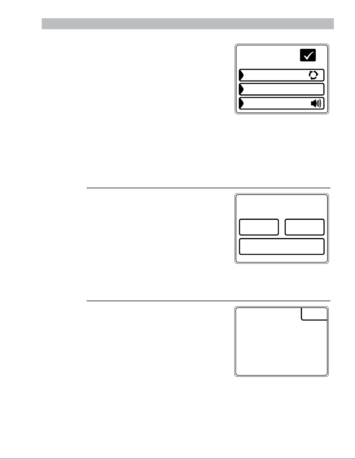
Adjusting
the Time
Settings
Touch the OPTIONS pad on the Touch Screen to
select drying options. After selecting any drying
options, press OK to save your setting.
Delay Start
Touch the DELAY START pad repeatedly to set a
delay time of up to 12 hours. The countdown time
will be shown in the display.
Extended Tumble
Minimizes wrinkles by adding approximately 20
minutes of no-heat tumbling after clothes are dry.
Touch EXTENDED TUMBLE to turn the feature
on or off. If set, the Extended Tumble time will
not be included in the cycle time shown in the
display. The dryer will signal for the first 6 minutes
during Extended Tumble.
End-of-Cycle Signal
Alerts you that the cycle is complete. The clothes
should be removed when the beeper goes off so
wrinkles won’t set in. Touch END OF CYCLE
SIGNAL to select the volume or to turn the
beeper off. The new volume will be saved as
the default setting.
You can adjust the time setting for the dry cycle,
delay start and extended tumble times. Touch the
TIME pad on the Summary Screen; then choose
the time you wish to adjust.
To change the dry cycle time, select CYCLE TIME;
then use the arrows to select more or less drying
time. If the Cycle Time is changed, the dryness
sensor will be turned off.
To change the delay start or extended tumble time,
select DELAY START or EXTENDED TUMBLE;
then follow the instructions in the About the
Drying Options section.
NOTE: After the dry cycle begins, you will not be
able to change the Cycle Time or Delay Time. The
dryer will beep twice if you try to change the times
after the cycle begins.
OPTIONS
DELAY START
EXTENDED TUMBLE
END OF CYCLE SIGNAL
ADJUST TIME SETTINGS
OK
20
MIN
CYCLE TIME DELAY TIME
EXTENDED TUMBLE
About the
Cycle Status
Screen
After you press START, a Cycle Status screen will
appear to indicate what cycle the dryer is in and
the time remaining in the cycle.
DRYING – The dryer is sensing the moisture level
of the load.
SENSING – The dryer is determining if the correct
dryness level has been reached.
:00 COOL DOWN – The load is dry and may be
removed (the dryer will continue to blow cool air
for up to 5 minutes).
:00 EXTENDED TUMBLE – The load is dry and
may be removed (the drum will continue to turn
without heat for up to 20 minutes).
– 11 –
CYCLE STATUS
:32
DRYING
CHANGE
SETTINGS
Page 12
Modifying,
Renaming
or Deleting
a “My Cycle”
To modify the settings of a “My Cycle” from the
Home Screen:
1 Press the MY CYCLES button.
2 Select MODIFY from the Touch Screen
menu.
3 Select the cycle name from the Touch Screen
menu.
4 Change any of the automatic settings and
select any options.
5 Press SAVE on the Touch Screen.
To delete a “My Cycle” from the Home Screen:
1 Press the MY CYCLES button.
2 Select DELETE from the Touch Screen
menu.
3 Select the cycle name from the Touch Screen
menu.
4 Choose YES to delete the cycle or CANCEL
to return to the list of “My Cycles.”
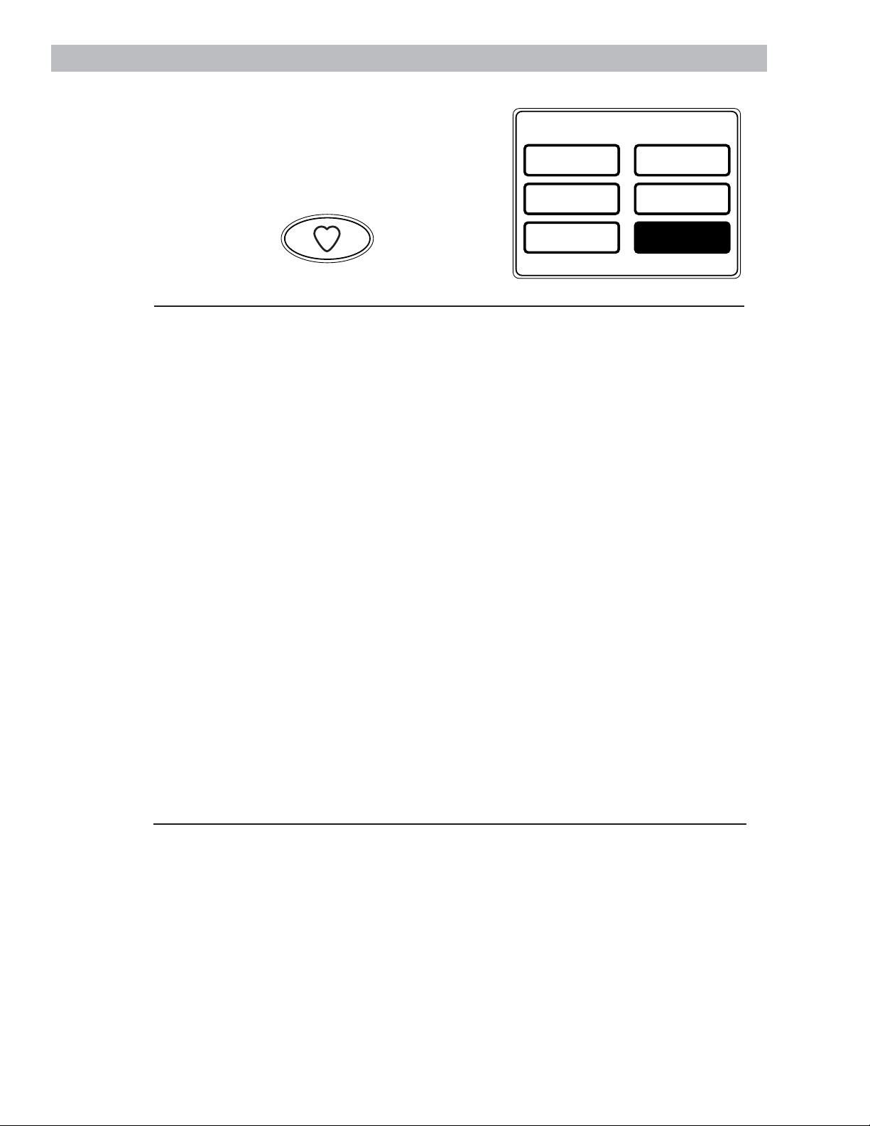
My Cycles
About the “My
Cycles” Feature
The “My Cycles” feature allows you to create,
store and reuse up to 6 custom cycles. Create
your own cycles from scratch or adjust the
settings of a predefined dry cycle; then save for
one-touch recall.
Creating
and Using a
“My Cycle”
You can create “My Cycles” two ways, by either
modifying a predefined dry cycle or creating a
cycle from your own combination of settings
and options.
To build your own “My Cycle” from the Home
Screen:
1 Press the MY CYCLES button.
2 Select CREATE from the Touch Screen
menu.
3 Choose whether you want to modify a
predefined cycle or create a new cycle.
4 If you are modifying a predefined cycle,
select the dry cycle you wish to modify.
5 Change any of the automatic settings and
select any options.
6 Touch SAVE on the Touch Screen.
7 Using the keypad on the Touch Screen, type
the name of your “My Cycle” and press OK.
To begin using your new “My Cycle” right away,
select it from the Touch Screen menu and press
START.
To save a current cycle as a “My Cycle” from the
Summary Screen:
1 After setting a dry cycle, or after a dry cycle
has just completed, press the MY CYCLES
button.
2 Select SAVE CURRENT SETTINGS from the
Touch Screen menu.
3 Using the keypad on the Touch Screen, type
the name of your “My Cycle” and press OK.
To begin using your new “My Cycle” right away,
select it from the Touch Screen menu and press
START.
To use a “My Cycle” from the Home Screen:
1 Press the MY CYCLES button.
2 Select USE from the Touch Screen menu.
3 Select the cycle name from the Touch Screen
menu.
4 Change any of the automatic settings and
select any options.
5 Press START.
MY CYCLES
USE MODIFY
C
Y
L
C
Y
M
E
S
CREATE RENAME
DELETE
SAVE CURRENT
SETTINGS
– 12 –
Page 13
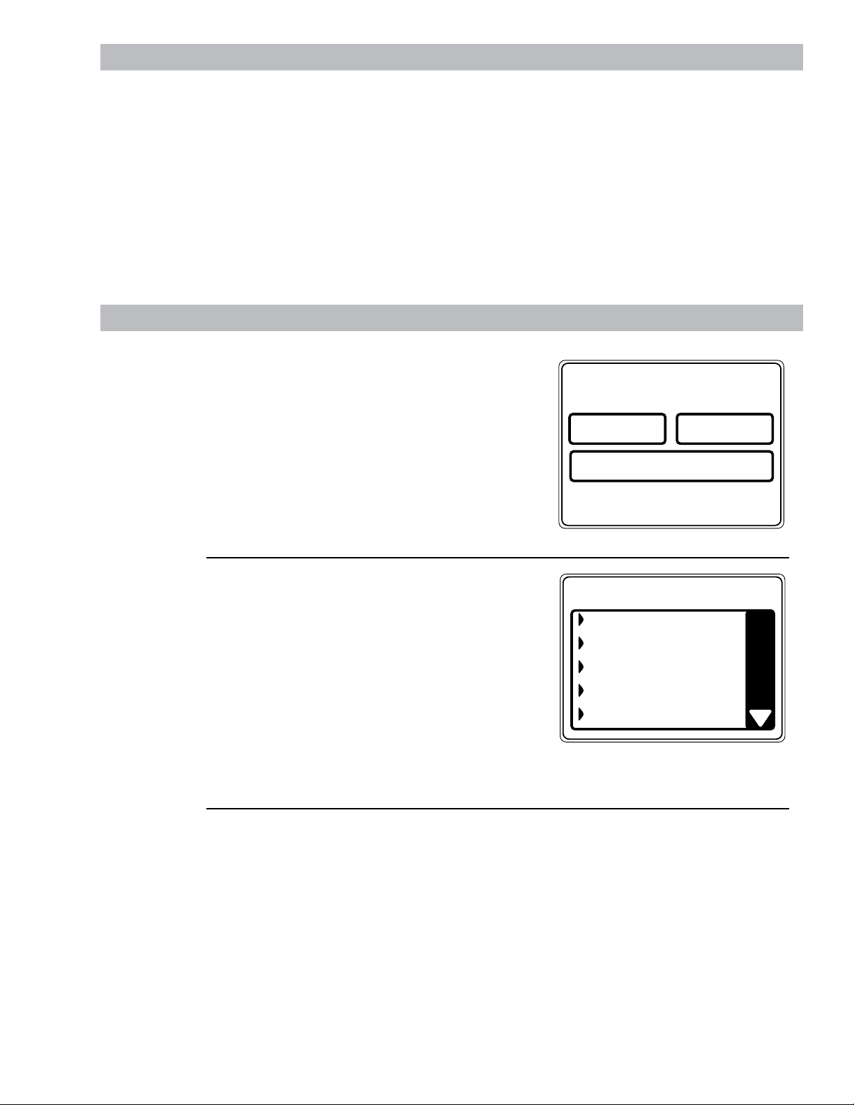
About
the Help
Feature
Pressing the HELP button from the Home
Screen allows you to locate troubleshooting tips
for common dryer problems, to find help with
using the Home Screen or to set machine
preferences.
Pressing the HELP button while on any other
screen allows you to find additional information
on features found on that screen. Press HELP;
then touch any pad on the Touch Screen for an
explanation of that feature. To exit the feature,
press HELP once to return to the previous
screen or twice to exit Help.
Using the
Troubleshooter
To locate Troubleshooting Tips for common
dryer problems:
1 Press the HELP button.
2 On the Touch Screen, select TROUBLE
SHOOTER.
3 On the Touch Screen, select the problem
description from the list. You can use the
arrows at the right of the screen to scroll up
and down through the list of additional
problems.
4 On the Touch Screen, select a possible cause
for the problem and follow the on-screen
instructions to find a solution.
Finding Help
Using the
Home Screen
Pressing the HELP button then selecting
HOME SCREEN HELP allows you to find
additional information on features found on
the Home Screen. Touch any pad on the Touch
Screen for an explanation of that feature. To
exit the feature, press the BACK button.
My Cycles
To rename a “My Cycle” from the Home Screen:
1 Press the MY CYCLES button.
2 Select RENAME from the Touch Screen
menu.
3 Select the cycle name from the Touch Screen
menu.
4 Using the keypad on the Touch Screen, type
the name of your “My Cycle” and press OK.
Consumer Help Screens
– 13 –
MACHINE
PREFERENCES
TROUBLE SHOOTER
TROUBLE SHOOTER
PRESS DESCRIPTION FOR POSSIBLE CAUSES
LONG DRY TIME
NOT HEATING OR NO HEAT
TOO MUCH HEAT
COLLARS OR WAISTBANDS WET
SQUEAKING DURING STARTUP
HOME SCREEN
HELP
Page 14
Consumer Help Screens
The machine settings on the Help feature
allow you to control the volume of the button
beep and end-of-cycle signal, and turn the
washer/dryer communication feature on
or off.
Press the HELP button, then select from the
on-screen options.
Button Beep
The button beep controls the volume of the
beep that is made when you press any of the
buttons on the control panel or Touch Screen.
To change the volume of the button beep:
1 From the Home Screen, press the HELP
button.
2 Select MACHINE PREFERENCES from the
Touch Screen.
3 Select BUTTON BEEP from the Touch
Screen.
4 Use the arrows to make the volume louder
or softer, or to turn the beep off.
5 Select OK from the Touch Screen.
The new volume is now saved as the default
setting.
Washer/Dryer Communication
Washer/Dryer communication allows your
dryer to receive cycle information from your
washer to create a dry cycle that matches your
wash load.
After the wash cycle is complete,
communication begins once either the washer
or dryer Touch Screen is activated.
Once the information is sent, your dryer can
then create the optimal dry cycle for your load.
To turn the Washer/Dryer Communication
feature on or off:
1 From the Home Screen, press the HELP
button.
2 Select MACHINE PREFERENCES from the
Touch Screen.
3 Select WASHER/DRYER
COMMUNICATION from the Touch
Screen.
4 Touch the pad at the bottom of the Touch
Screen to select ON or OFF.
5 Select OK from the Touch Screen.
End-of-Cycle Signal
The End-of-Cycle signal alerts you when the
cycle is complete.
To change the volume of the end-of-cycle
signal:
1 From the Home Screen, press the HELP
button.
2 Select MACHINE PREFERENCES from the
Touch Screen.
3 Select END OF CYCLE SIGNAL from the
Touch Screen.
4 Use the arrows to make the volume louder
or softer, or to turn the signal off.
5 Select OK from the Touch Screen.
The new volume is now saved as the default
setting.
Setting the
Machine
Preferences
MACHINE PREFERENCES
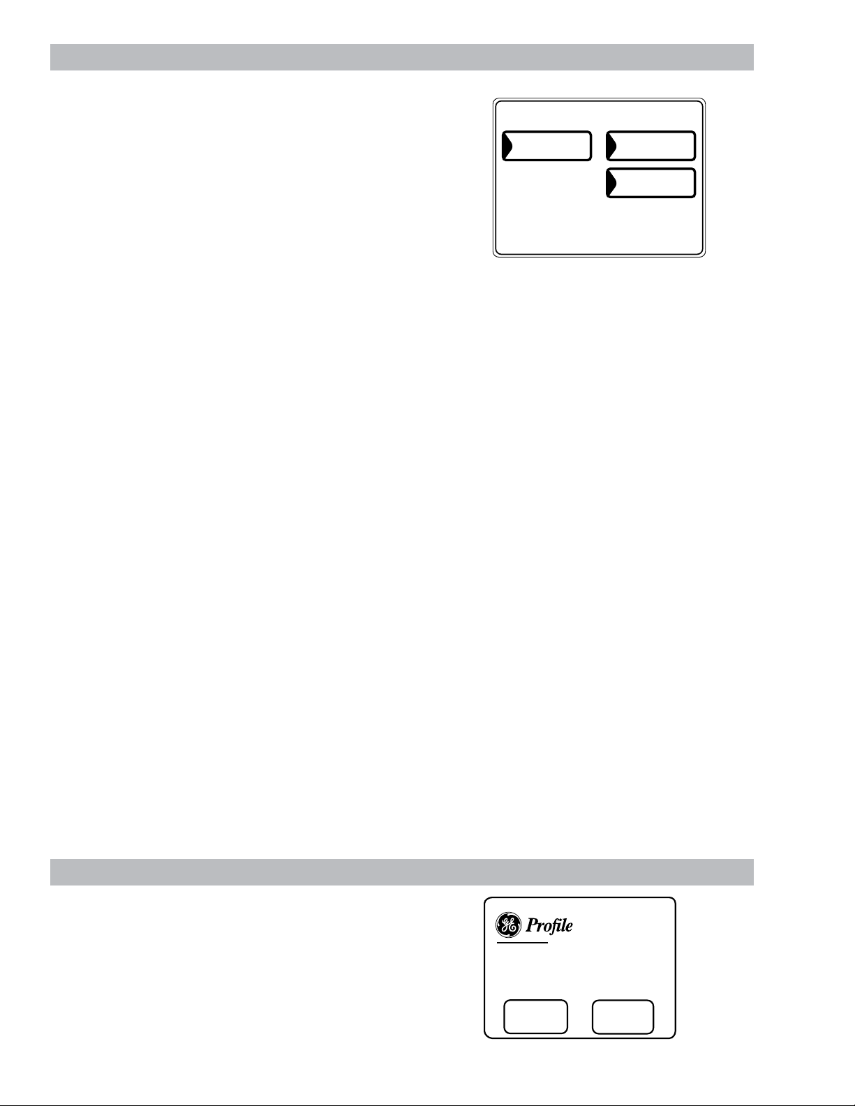
Sales Demo Mode
Pressing HOME and MY CYCLES simultaneously
for three seconds will enter into the sales
demonstration mode. This mode allows the user
to view a dryer cycle. To exit, press HOME and
MY CYCLES simultaneously for three seconds or
disconnect the power to the machine.
END OF CYCLE
SIGNAL
Harmony Clothes
The Washer Talks, The Dryer Listens
The Result is Better Clothes Care
LEARN
MORE
CONTROLS
– 14 –
BUTTON BEEP
WASHER/DRYER
COMMUNICATION
Care System
TRY THE
Page 15
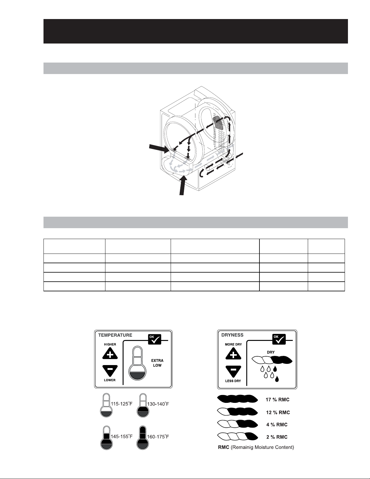
Operation Overview
Airflow Diagram (Gas and Electric Models)
LINT
FILTER
EXHAUST AIR
INLET
AIR
AREA
Dryer T emperature Settings (Gas and Electric Models)
DRYER TEMPERAT URE
SETTING
EXTRA LOW 10.5 AM PS 115F - 125F 2500 W 15000 BTU
LOW 16 AM PS 130F - 140F 4000 W 18000 BTU
ME DIUM 19 AM PS 145F - 155F 5000 W 22000 BTU
HIGH 24 AM PS 160F - 175F 6000 W 25000 BTU
APP RO XI M AT E CURRENT
DRAW (L1)
Note: Above measurements are at 70°F ambient temperature with no clothes load and vent
disconnected.
APPROXI MATE T EMPERATUR E
AT LINT FILTER
ELE CTR IC MO D EL
GAS MODEL
– 15 –
Page 16
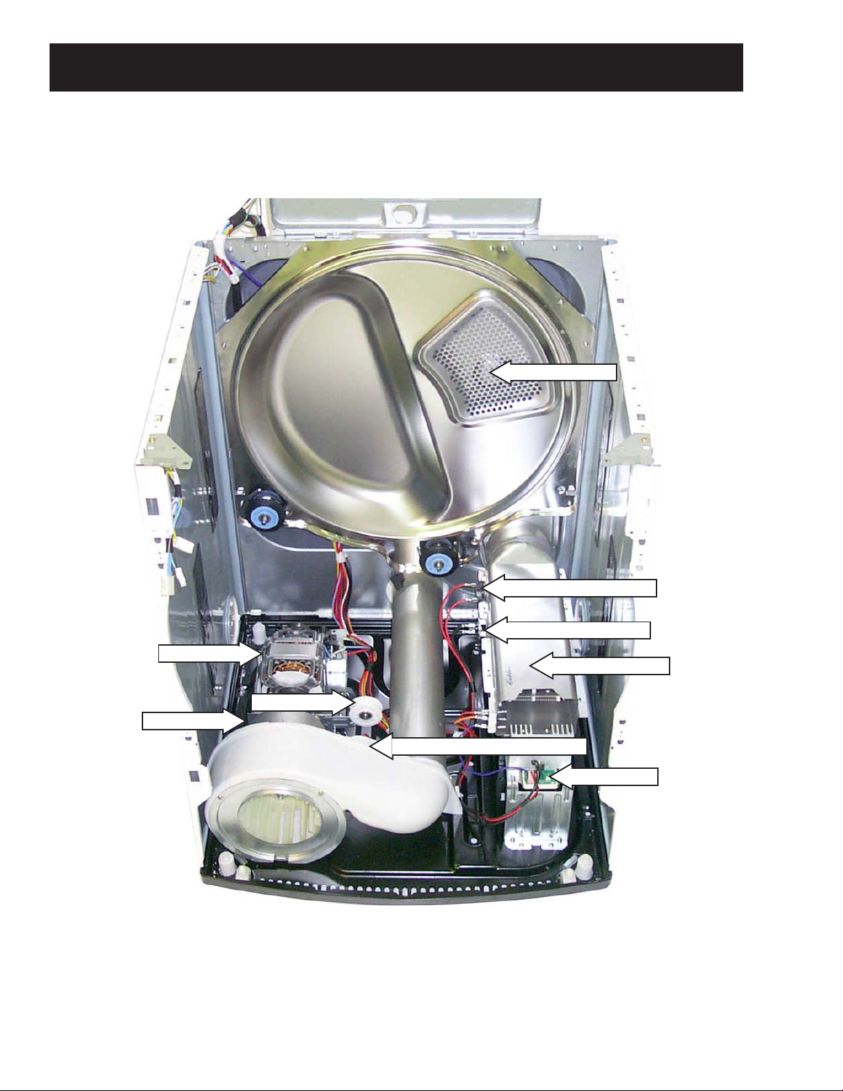
Electric Model
Component Locator Views
Inlet Thermistor
Drive Motor
Blower Motor
Inlet Hi-Limit Thermostat
Inlet Safety Thermostat
Heater Housing
Idler Pulley
Outlet Thermistor & Thermostat
TRIAC Board
– 16 –
Page 17
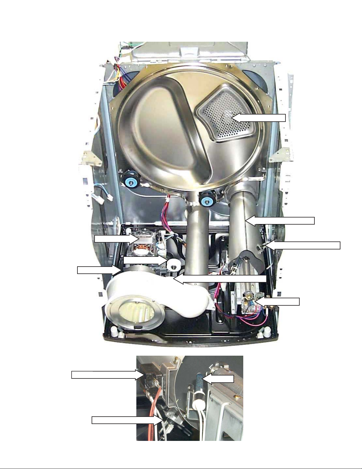
Gas Model
Inlet Thermistor
Drive Motor
Idler Pulley
Blower Motor
Flame Sensor (Detector)
Combustion Chamber
Inlet Hi-Limit Thermostat
Outlet Thermistor & Thermostat
Gas V alve
Ignitor
Inlet Safety Thermostat
– 17 –
Page 18
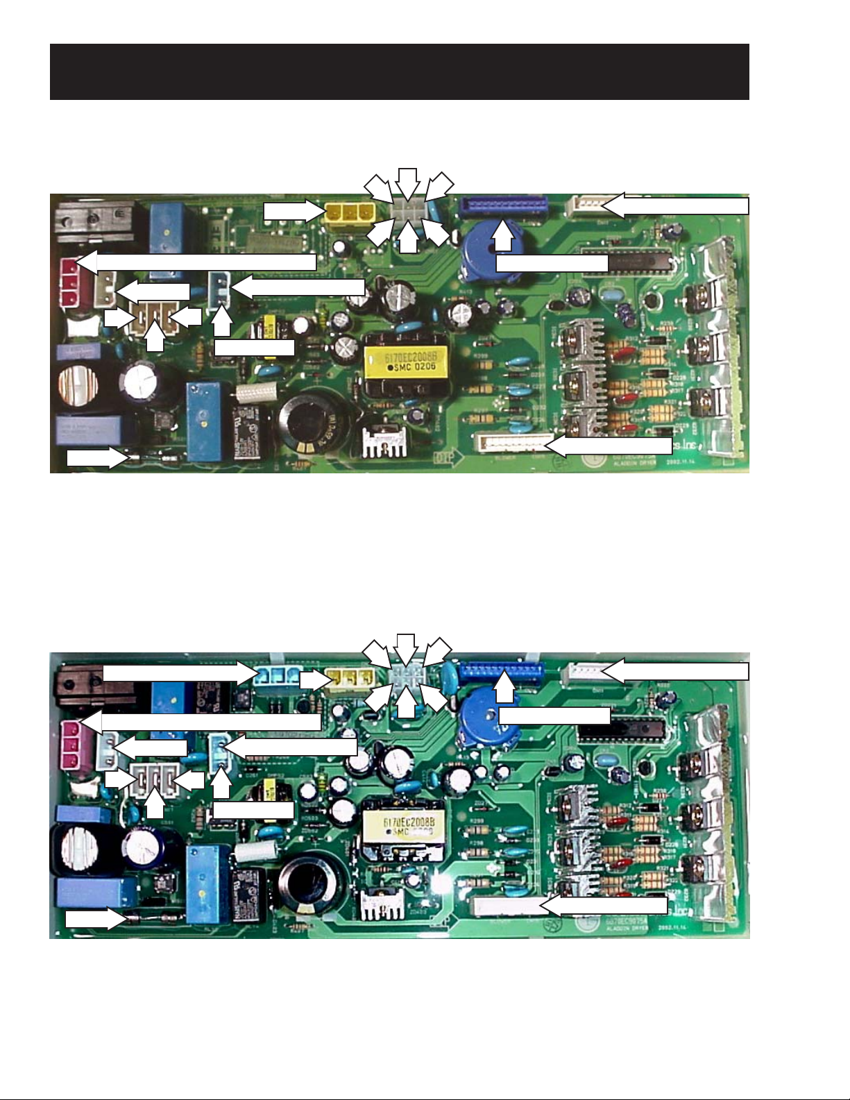
Inverter and Main Board Pin Connectors
Inverter Board (Electric Model)
Triac
120 VAC Input From RF Choke CN10
5
4
3
1
Main Board CN11
1
2
Main Board CN14
Ground
6
Fuse
1-Moisture Sensor
2-Inlet Thermistor
7
7
Door Switch
3-Inlet/Outlet Thermistor
4-Ground
Inverter Board (Gas Model)
Gas Valve ON/OFF
120 VAC Input From RF Choke CN10
Safety Thermostat
8
Blower Motor
5-Inlet Thermistor
7-Drum Motor
6-Heating Coil
5
4
3
1
Main Board CN11
1
2
Main Board CN14
Ground
6
7
Fuse
1-Moisture Sensor
2-Inlet Thermistor
Safety Thermostat
7
Door Switch
3-Inlet/Outlet Thermistor
4-Ground
– 18 –
5-Inlet Thermistor
6-Linear Gas V alve
Blower Motor
7-Drum Motor
8-Flame Sensor
Page 19
Main Board
LCD Backlight (>800 VDC)
Touch Screen
LCD Display
Serial Communication Link
Inverter
Keypanel Membrane
Model Selector Connector
WARNING: THE CONNECTOR AT THE LCD BACKLIGHT IS OVER 800 VDC. USE APPROPRIATE
TYPE VOLTMETER OR DAMAGE COULD RESULT.
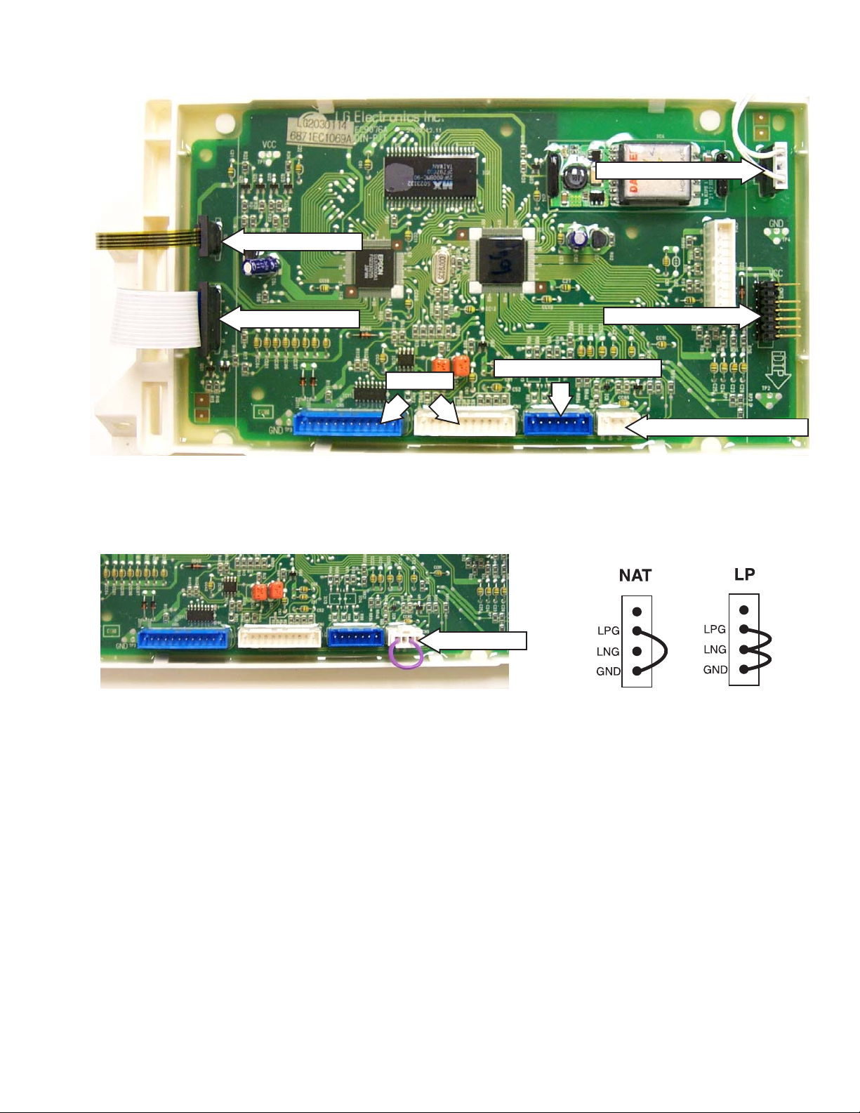
Jumper Configurations
Jumper Plug
Note: The gas dryer main board differs from the electric dryer main board by the addition of a jumper
plug on the model selector connector (the electric model has no jumper plug). Depending on how the
pins have been jumped will determine what type of gas (natural or LP) the dryer is using.
The LP conversion kit is part number WE25X10014 and consists of the LP model selector and an LP
orifice for the gas valve.
The dryer control performs three checks to determine whether the dryer is an electric, LP gas or natural
gas.
• Initially , the control looks for a flame sensor. If the flame sensor is detected, the control then looks for
a model selector set for natural or LP gas.
• If both conditions are satisfied, the dryer will start.
• The dryer control then monitors temperature based on specific software parameters for each type of
gas. If the temperature is outside of that range, an error is displayed on the LCD display and the
dryer will shut down. (See
Error Chart Gas Setup Failed).
– 19 –
Page 20

Dryer Components
Backsplash
The backsplash must be removed to access the
control system components.
To remove the backsplash:
1. Remove the 4 Phillips head screws that hold
the backsplash in place.
Backsplash
2. Place a towel over the lid of the dryer to
prevent scratches to the surface. Gently lift
each corner of the backsplash; then roll it
forward so it rests on top of the dryer .
Main Control Board and Touch Screen
LCD
The main control board and touch screen LCD
are attached to the backsplash as one unit. The
touch screen LCD and main control board are
only available as a complete assembly .
To remove the main control board and LCD
touch screen assembly:
1. Remove the
2. Disconnect the ribbon at the right of the main
control board.
Note: Do not disconnect any other ribbons from
the main control board.
Backsplash.
3. Disconnect the wiring to the control board.
Remove the backsplash.
Control System
The dryer control system consists of three main
components:
• Main control board and touch screen LCD
• Membrane keypanel
• Inverter
Caution: To prevent electrostatic discharge from
damaging any electronic components, use an
ESD wristband or touch a grounded metal
surface before servicing.
Disconnect Ribbon
3. Remove the 4 Phillips head screws (2 on
each side) that hold the main control board
and LCD touch screen assembly in place.
Remove the assembly.
– 20 –
Page 21

Membrane Keypanel
Inverter
The membrane keypanel is attached to the
backsplash and is available only as a complete
assembly.
• When ordering a replacement backsplash, the
part must be ordered as left or right,
depending upon installation.
• The membrane keypanel is connected to the
control board by a ribbon cable.
Membrane Keypanel Test
To test the membrane keypanel, press the
appropriate pad and check for continuity (0 Ω)
between the following pins:
Pad Pins
Power 1 and 3
My Cycles 1 and 4
Back 2 and 3
Help 2 and 4
Home 1 and 7
Start/Stop 1 and 5
The inverter board is enclosed in a protective box
mounted on the top panel under the backsplash.
To access and remove the inverter board:
1. Remove the
2. Remove the 2 Phillips head screws that hold
the inverter box in place.
3. Slide the inverter box toward the rear of the
dryer and lift out.
Backsplash.
7
5
4
3
2
1
Note: The number 1 molded on the membrane
connecter is not a pin reference number.
1
MEMBRANE
RIBBON
4. Lift the inverter box up. Press the tabs on the
side and gently pry it open
5. Disconnect the wiring from the inverter board.
Remove the inverter.
– 21 –
Page 22

T esting the Inverter
r
Signal (Beeper)
CN14
120 VAC Input From RF Choke CN10
Fuse
CN11
• The inverter receives 120 V AC at the red 3-pin
connector CN10. The voltage first passes
through an RF choke. The RF choke filters the
line voltage and is replaced as an assembly. If
120 V AC is not present, check the wall outlet,
power cord, and RF choke.
• When 120 V AC is present at CN10, there
should be 5 VDC between pin 3 (white wire)
and pin 7 (blue wire) on the white connector
CN1 1. (This voltage is used to keep the
membrane and LCD display in standby,
waiting for a key-press.)
The beeper is mounted on the inverter, but
controlled by the main control board.
• The beeper uses the same 12 VDC supply as
the LCD backlight.
• To check the 12 VDC circuit, measure
between pin 3 (white wire) on white connector
CN1 1 and pin 8 (pink wire) on the blue
connector CN14. (See
Pin Connectors.
12 11
109876
1110987654321
)
Inverter and Main board
CN14
54321
CN11
• Upon activating a membrane pad or touching
the LCD screen, the control "wakes up" and a
second transformer is energized. When this
condition is present, 12 VDC and 20 VDC can
be measured on the board.
• 12 VDC should be between pin 3 (white wire)
on white connector CN1 1 and pin 8 (pink wire)
on the blue connector CN14.
• 20 VDC should be between pin 3 (white wire)
on white connector CN1 1 and pin 12 (brown
wire) on the blue connector CN14.
Voltage CON Pin
120 VAC CN10 1 BLK CN10 3 WHT
5 VD C CN11 3 WHT CN11 7 BLU
12 VDC C N11 3 WHT CN14 8 PNK
20 V DC CN11 3 WHT CN1 4 1 2 B RN
Wire
Color
CON Pin
Wire
Colo
– 22 –
Page 23

Top Cover
Front Panel
The top cover is held in place by 2 Phillips head
screws, located on the back of the washer,
and two front tabs.
To remove the top cover:
1. Remove the Backsplash.
2. Remove the 2 screws that hold the
box in place.
3. Place the inverter box off to the side of the
dryer.
4. Slide the wiring harness guard out.
Disconnect the wires to the RF choke/surge
protector.
Inverter
WARNING: Sharp edges may be exposed when
the inner top cover is removed. Use caution to
avoid injury when servicing dryer . Wear Kevlar
gloves or equivalent protection.
To remove the front panel:
1. To access the 2 top Phillips head screws
securing the front panel, remove the
backsplash and top cover .
2. Open the door and remove the 4 Phillips
screws from the front panel.
5. Remove the 2 rear Phillips head screws that
hold the top cover in place.
6. Lift the top cover and slide it forward to clear
the front tabs.
3. Remove the 2 Phillips screws that hold the
front panel to the inner top cover .
4. Lift and tilt the front panel forward slightly to
disconnect wiring to the door switch.
Door Switch
5. Remove the front panel .
– 23 –
Page 24

Drum
WARNING: Sharp edges may be exposed.
Wear Kevlar gloves or equivalent protection.
The dryer drum is made of 304 stainless steel
and has three replaceable drum baffles attached
to the inside. The drum rotates clockwise at 47 to
50 rpm.
4. Remove the 4 screws that hold the front drum
support to the sides of the dryer.
To remove the drum:
1. Remove the
Top Cover and the Front Panel.
2. The heat shield is held in place by 4 Phillips
head screws (2 on each side) and 2 plastic
rails (1 on each side). Remove the screws
that hold the plastic rails in place. Slide the
rails forward and out.
Tech Tip: The drum can be removed without
removing the heat shield if desired. However,
installation and removal of the dum can be difficult
due to the limited space around the drum if the
heat shield is left in place.
Front Drum Support
5. Grasp the top outside edges of the front drum
support and unsnap the 4 corners from the
from the sides of the dryer. Remove the front
drum support.
6. Remove the
Drive Belt from the motor.
7. Using the belt as a handle, pull the drum
forward and guide it out of the dryer cabinet.
Rail
Rail
3. Disconnect wiring to the drum light and
sensor rods.
Disconnect Drum Light
Disconnect Sensor Rods
– 24 –
Page 25

Drum Rollers
Door Switch
The 304 stainless steel drum rotates on four drum
rollers. Two on the front drum support and two on
the rear drum support.
The drum roller comes as a complete assembly.
To remove the drum rollers:
1. Remove the
2. Remove the front drum support to access the
front drum rollers. Remove the
access the rear drum rollers.
Top Cover and Front Panel.
Drum to
The door switch is fastened to the front panel by
two locking tabs and is common to all dryer
functions.
• When the dryer door is closed, the switch will
complete the motor circuit, allowing dryer
operation.
• Immediately upon detection of a door opening,
the drum motor and blower motor shut off and
all heat is disabled.
• If the door is open at the start of a cycle or
while a cycle is running, the SUMMARY
SCREEN is displayed on the LCD screen.
• Once the door is closed, the dryer pauses and
the SUMMARY SCREEN is displayed showing
cycle parameters and the current estimated
cycle time remaining.
• The dry cycle can be resumed by pressing the
START/STOP pad.
• Opening the dryer door closes the drum light
circuit, allowing the drum light to be energized.
3. Each drum roller is held in place by a plastic
triangular clip.
4. Remove the plastic triangular clip with a small
flat-blade screwdriver and remove the drum
roller.
5. To remove the drum roller shaft from the front
drum support, remove the 14 mm hex nut that
holds the shaft in place.
6. To remove the drum roller shaft from the rear
drum support:
a. Remove the Heater Assembly.
b. Remove the seven screws from the back
of the dryer that hold the rear drum
support in place.
c. Remove the 14 mm hex nut that holds the
drum roller shaft in place.
• The door switch circuit can be checked in the
factory test mode.
– 25 –
Page 26

Drum Light
To install the drive belt:
The drum light has a screw-in 15-watt, 120-VAC
bulb located in the top of the front panel. It is
switched on the neutral side by the door switch.
• Replace only with a bulb of the same size and
type. (The bulb can be found at most local
stores).
• Remove the screw in the bulb lens to access
the bulb.
Screw
1. Place the belt in position around the front of
the drum.
2. Reach under the left side of the drum and
place the belt in position around the motor
pulley . Push the idler pulley to the left and
place the belt onto the idler pulley .
3. Release the idler pulley and guide the belt into
position.
4. Install the
Drum support.
Note: Lift the drum slightly to line up the drum
with the drum support.
5. Check to make sure the belt is in place and
not twisted before installing the top and front
panels.
Belt Switch
The belt switch is fastened to the motor bracket
by 2 Phillips head screws.
Drive Belt
The drive belt extends from the motor pulley , p ast
the idler pulley , and around the perimeter of the
dryer drum. Part # WE12X1001 1.
To remove the drive belt:
1. Remove the
2. Reach under the left side of the drum, push
the idler pulley to the left to take tension off the
belt.
3. Remove the belt from the motor pulley and
idler pulley . Pull the belt through the front of the
dryer.
Top Cover and Front Panel.
Idler Pulley
Belt
• The belt switch is activated by the idler pulley .
• If the drive belt breaks, the belt switch opens
the drive motor circuit, interrupting all dryer
functions except the drum lamp.
Idler Pulley
Belt Switch
To remove the belt switch:
1. Remove the
Top Cover, Front Panel, and Drum.
2. Disconnect the wiring to the belt switch.
3. Remove the 2 Phillips head screws that hold
the belt switch to the motor bracket.
Motor Pulley
– 26 –
Page 27

Drive Motor
Blower Motor
The drive-motor is a single-speed AC, 1/3-hp
motor with an automatic reset overload protector.
• The overload protector is an internal
component of the motor and cannot be
replaced separately .
• The motor contains a centrifugal switch that
serves three purposes:
1. Disengages the motor start winding.
2. Engages the motor run winding.
3. Closes the circuit contacts for the heat
source.
• The switch is an internal component of the
motor and cannot be replaced separately.
The drive motor has an approximate resistance
value of:
•3 Ω between the blue and white wires
•7 Ω between the brown and blue wires.
• 10 Ω between the brown and white wires.
To remove the drive motor:
1. Disconnect power to the unit.
2. Remove the
Top Cover , Front Panel, and Drum.
3. Disconnect the motor wiring.
4. With a flat blade screwdriver, compress the
open end of the spring strap (one strap on
each end of the drive motor) until it releases.
The blower motor is a DC, variable speed motor
capable of operating at different speeds in
response to changing air temperature and venting
impedances. Below 1000 rpm, the dryer control
turns the heater off.
Resistance of the motor windings can be
measured at the 10-pin connector on the inverter
board or at the motor. (See
Board Pin Connectors
).
Inverter and Main
The blower motor has an approximate resistance
value of 14 Ω between the following wires:
• Y ellow to Yellow
• Red to Red
• Blue to Blue
The remaining wires are a ground and feedback
through the control for determining motor speed.
To remove the blower motor:
The blower housing must be removed to access
the blower motor .
1. Disconnect power to the unit.
2. Remove the
Top Cover , Front Panel, and Drum.
3. Disconnect the outlet thermistor and outlet
thermostat wiring located on the back side of
the blower housing.
4. Disconnect the motor wiring.
Disconnect
Spring Strap
5. Remove the spring straps. Remove the drive
motor from its cradle.
Outlet Thermostat Wiring
Outlet Thermistor Wiring
Motor Wiring
(Continued next page)
– 27 –
Page 28

5. Remove the 2 Phillips head screws that hold
the blower guard in place. Remove the blower
guard.
6. Remove the 13 mm center nut. (Turn
clockwise to remove.) Remove the blower
wheel.
8. Remove the remaining 2 Phillips head screws
from the dryer base and exhaust duct.
Top View
Note: The motor shaft has a snap ring, which
prevents the blower wheel from rubbing the back
of the blower housing.
7. Remove the 3 Phillips head screws from the
center of the blower housing. Remove the
front screw from the dryer base.
Snap Ring
9. Remove the blower housing.
10. With a flat blade screwdriver compress the
open end of the spring strap (one strap on
each end of the drive motor) until it releases.
Spring Strap
11. Remove the spring straps. Remove the drive
motor from the motor bracket.
Note: The motor bracket is notched, be sure to
align the motor correctly in the bracket when
installing.
– 28 –
Page 29

Heater Assembly (Electric Models)
The electric dryer has two heating elements. One
is fixed at 3000 watts and cycles on and off. The
other is variable, controlled by a Triac that varies
the wattage from 0 to 3000 watts.
• The total wattage of the dryer will vary from
3000 to 6000 watts.
• The open end in the back of the housing
allows air to be drawn over the heating coils
and into the drum.
• Each row of coils should have a resistance
value of 17 Ω.
Heater Assembly
3. Remove the 2 Phillips head screws that hold
the heater assembly in place.
4. Remove the heater assembly.
To remove the heater assembly:
1. Remove the
Top Cover, the Front Panel, and
the Drum.
2. Note the wire locations and disconnect all
wiring to the heater assembly .
– 29 –
Page 30

Inlet Thermistor
Inlet Safety Thermostat
The inlet thermistor is located on the inside of the
inlet air duct on both electric and gas models.
Inlet Thermistor
• The inlet thermistor measures the incoming
air temperature and responds to temperature
changes.
• The inlet thermistor provides temperature
change information to the electronic control
board.
The inlet safety thermostat is located on the left
side of the heater housing on electric models and
on the lower, left side of the combustion chamber
on gas models.
Electric Model Location
Manual Reset
• The electronic control board makes heating
and blower decisions based on this
information.
• At room temperature the inlet thermistor has a
resistance value of 2.27 K Ω +/- 5%.
To remove the thermistor:
1. Remove the inlet thermistor access cover
located on the back of the dryer.
2. Disconnect the thermistor wiring.
Screw
Disconnect
Gas Model Location
Manual Reset
3. Remove the screw that holds the thermistor in
place. Remove the thermistor.
– 30 –
Page 31

• The inlet safety thermostat monitors incoming
air temperature.
• If the thermostat reaches a temperature
beyond its maximum temperature rating, it will
trip and disable all dryer functions except the
drum lamp.
• The outlet thermistor measures outgoing air
temperature and responds to temperature
changes.
• The outlet thermistor provides temperature
change information to the electronic control
board.
• The inlet safety thermostat must be reset
manually by pressing the reset button on the
back of the thermostat (see photos).
• The inlet safety thermostat on the electric
models has a trip temperature of 212°F
(100°C).
• The inlet safety thermostat on the gas models
has a trip temperature of 266°F (130°C).
To remove the safety thermostat:
1. Remove the
Top Cover, Front Panel, and Drum.
2. Disconnect the safety thermostat wiring.
3. Remove the 2 screws that hold the safety
thermostat in place. Remove the safety
thermostat.
Outlet Thermistor
The outlet thermistor is located on the blower
housing on both the gas and electric models.
• The electronic control board makes heating
decisions based on this information.
• At room temperature the outlet thermistor has
a resistance value of 10 K Ω +/- 3%.
To remove the outlet thermistor:
1. Remove the
Top Cover, Front Panel, and Drum.
2. Disconnect the thermistor wiring.
3. Remove the screw that holds the thermistor in
place. Remove the thermistor.
Outlet Thermostat
The outlet thermostat is located on the blower
housing on both the gas and electric models (see
photos.)
• The outlet thermostat monitors outgoing air
temperature.
• If the outlet thermostat reaches a temperature
beyond its maximum temperature rating, it will
trip and disable the heating function only .
Outlet Thermostat
Outlet Thermostat
Outlet Thermistor
Outlet Thermistor
• The heating function will be restored when the
outlet thermostat cools and resets.
• The outlet thermostat on the electric model
has a trip temperature of 189°F (87°C) and a
reset temperature of 153°F (67°C).
• The outlet thermostat on the gas model has a
trip temperature of 185°F (85°C) and a reset
temperature of 149°F (65°C).
To remove the outlet thermostat:
1. Remove the
Top Cover, Front Panel, and Drum.
2. Disconnect the thermostat wiring.
3. Remove 2 Phillips head screws that hold the
outlet thermostat to the blower housing.
Remove the outlet thermostat.
– 31 –
Page 32

Hi-Limit Thermostat
To remove the hi-limit thermostat:
The hi-limit thermostat is located on the left side
of the heater housing on electric models. It is
located on the right, upper side of the combustion
chamber on gas models.
Electric Model Location
Gas Model Location
1. Remove the
the
Drum.
Top Cover, the Front Panel, and
2. Disconnect the lead wires to the hi-limit
thermostat.
3. Remove the 2 screws that hold the hi-limit
thermostat to the housing. Remove the hi-limit
thermostat.
Gas Valve
The gas valve assembly is located in the bottom,
right, front corner of the dryer cabinet.
Gas Valve
• The hi-limit thermostat monitors incoming air
temperature.
• If the hi-limit thermostat reaches a
temperature beyond its maximum
temperature rating, it will trip and disable the
heating function only .
• Heating functions will be restored when the hilimit thermostat cools and resets.
• The hi-limit thermostat on the electric models
has a trip temperature of 230°F (110°C) and a
reset temperature of 194°F (90°C).
• The hi-limit thermostat on the gas models has
a trip temperature of 194°F (90°C) and a reset
temperature of 158°F (70°C).
• The gas valve consists of 3 valves operated
by 12 VDC solenoid coils.
• Two of the valves are either in an open or
closed state, depending on whether the coils
are energized by the control.
• The resistance value of these coils is
approximately 1900 Ω.
• The third valve is a linear valve. The valve
opening varies depending on the amount of
voltage it receives from the electronic control.
The resistance of the coil on the linear valve is
approximately 65 Ω.
– 32 –
Page 33

• The control operates the gas valves by
supplying voltage based on varying duty
cycles.
• It is difficult to determine specific voltages at
the valve due to software algorithms based on
clothes load and temperature settings. The
most accurate diagnostic check is to measure
resistance of the solenoid coils.
Ignitor
The ignitor is located at the end of the gas valve
assembly in the combustion chamber opening.
Resistance across the ignitor is approximately
300 to 500 Ω.
Combustion Chamber
To remove the gas valve:
1. Shut off the gas and electricity to the dryer .
2. Remove the
Top Cover, and Front Panel.
3. Disconnect all wiring to the gas valve and
ignitor.
4. Remove the 2 Phillips head screws that hold
the gas valve to the elbow coupling.
5. Remove the 2 Phillips screws that hold the
gas valve assembly to the dryer base.
Elbow Coupling
Dryer Floor
Ignitor
Gas Valve Assembly
To remove the ignitor:
1. Shut off the gas and electricity to the dryer .
2. Remove the
Top Cover, Front Panel, and Drum.
3. Using a short Phillips screwdriver, remove the
screw that holds the ignitor to the assembly.
Remove the ignitor.
Note: There is a cutout on the edge of the
combustion chamber to allow access to the
screw.
6. Slide the gas valve assembly out through the
front of the dryer cavity .
7. Remove the 3 Phillips head screws that
secure the gas valve to the mounting
assembly. Remove the gas valve.
Screw
– 33 –
Page 34

Ignitor and Flame Detector
Moisture Sensor
• When the electronic control calls for heat,
120 V AC is supplied to the ignitor .
• The flame detector, which is in series with the
ignitor, is closed.
• When the ignitor reaches a high enough
temperature, the flame detector opens.
• The electronic control senses the opening of
the detector and energizes the gas valves.
Testing the Ignitor and Flame Detector Circuit
1. Place the dryer in Factory Test Mode:
a. Press HOME, then HELP.
b. Press and hold the HELP and START/
STOP pads simultaneously for 3 seconds.
2. Press START/STOP to begin the test.
• The FLAME SENSOR test will display
whether the detector is open or closed.
The moisture-sensing circuit consists of two
sensor rods mounted in the drum front beneath
the lint filter opening.
• The sensor rods are connected to the main
control board. The rods are spaced about
½ in. apart, which creates an open circuit to
the control.
• The control board utilizes a low-voltage
capacitor that charges to approximately 5
VDC when the circuit is open and discharges
to less than 1 VDC when the circuit is shorted.
• When wet clothes tumble across the two
rods, the clothes create a very low resistance
between the rods, which discharges the
capacitor.
• As the clothes become dry, their resistance
value increases and the charge across the
capacitor builds to approximately 5 VDC.
• In the OFF position, the flame detector is
closed (room temperature/low heat).
ON position, the flame detector is open
(hot).
In the
Sensor Rods
Note: Proper leveling of the dryer is vital for
accurate sensor drying. Excessive rearward
adjustment will cause clothes to tumble toward
the rear of the drum, preventing contact with the
senor rods, thus producing a false dryness
reading.
Testing the Moisture Sensor Circuit
1. Place the dryer in Factory Test Mode:
a. Press HOME, then HELP.
b. Press and hold the HELP and START/
STOP pads simultaneously for 3 seconds.
A dry sensor rod circuit should display a voltage of
4.75 V AC or higher under MOISTURE(S) test.
2. Wet a cloth and place it across the sensor
rods. The display voltage should drop to
1.0 VAC or less if the circuit is working
correctly.
– 34 –
Page 35

Field Service Mode
Overview
The dryer control has a field service mode that
can be accessed by the service technician in
order to give critical information on the status of
various components of the dryer. This mode will
aid the service technician in quickly identifying
failed or improper operation of components and
systems.
The service mode does not use error codes to
identify problems. Instead, the LCD screen
displays a list of components or systems to be
checked if a problem is detected.
To enter the service mode:
Note: Once the service mode is entered all
membrane keypanel buttons are disabled.
1. Press the POWER key to turn the dryer on.
a. If the dryer is on and the home screen is
displayed, proceed to step 2. If the home
screen is not displayed, press HOME on
the keypanel.
TOUCH TO SELECT
Sensor
DRY CYCLE
3. Press and hold MY CYCLES and BACK
simultaneously for 3 seconds:
• The control will display any recorded
errors. If no errors have been recorded,
press EXIT to return to the HOME screen.
SERVICE MODE DIA GNOSTICS
THERE ARE NO SERVICE PROBLEMS
DETECTED WITH THIS UNIT.
EXIT
4. If errors have been recorded, use the error
chart in the
Troubleshooting for proper
diagnostic procedures.
SERVICE MODE DIAGNOSTICS
THERE IS A PROBLEM WITH THE HEATER BOX.
PLEASE CHECK AND REPLACE IF NECESSARY.
REMEMBER T O ALWAYS UNPLUG UNIT
PRIOR T O ANY SER VICING
MAIN : MV1.00
INV . : V01.01
EXIT
BY
FABRIC
SPECIAL
CYCLES
BY
GARMENT
TIMED DRY
2. Press HELP. The main help screen is
displayed.
MACHINE
PREFERENCES
TROUBLE SHOOTER
HOME SCREEN
HELP
– 35 –
• A MORE icon will be displayed on the LCD
screen if additional problems have been
recorded. Press MORE to list additional
errors.
SERVICE MODE DIAGNOSTICS
THERE IS A PROBLEM WITH
THE INLET THERMIST OR.
PLEASE CHECK AND REPLACE IF NECESSARY.
REMEMBER T O ALWAYS UNPLUG UNIT
PRIOR T O ANY SER VICING
MAIN : MV1.00
INV . : V01.01
EXIT
MORE
• Use the BACK pad on the keypanel
membrane to scroll back through the list. If
MORE is not displayed, then there are no
additional errors.
(Continued next page)
Page 36

YOUR DRYER IS NOW
READY FOR YOUR USE.
PLEASE READ YOUR
USER'S MANUAL PRIOR
TO OPERATION.
OK
5. If errors have been recorded, the following
steps MUST be performed.
a. Make a note of the listed errors. Press
EXIT; the screen prompts you to unplug
the dryer before servicing.
SERVICE MODE DIAGNOSTICS
ATTENTION
IN ORDER TO EXIT THE SERVICE MODE
THE UNIT MUST BE UNPLUGGED AND
SERVICED. THE UNIT WILL
AUTOMATICALLY RUN A SETUP POUTINE
AND SELF-DIAGNOSTICS UPON BEING
PLUGGED BACK IN.
Note: Pressing EXIT clears all error messages
and activates the setup mode program.
b. Disconnect power and make necessary
repairs.
c. After the problem has been identified in
service mode and repairs have been
made, the unit prompts the service
technician to run a setup/self diagnostic
check. The self diagnostic check consists
of a series of system tests to ensure the
dryer is operating correctly . Follow the onscreen instructions.
IMPORT ANT: Always disconnect power ,
reconnect power and run the setup/self
diagnostic mode prior to leaving the house. If
this process is not completed and a power
outage should occur, the setup/self
diagnostic mode screen will be displayed for
the customer. This may generate a second
service call when no problem exists.
d. When all errors have been corrected and
the setup/self diagnostic mode has been
completed, the dryer displays the following
screen.
e. Press OK to return the dryer to normal
operation.
CONGRATULATIONS ON THE
PURCHASE OF YOUR NEW GE
PROFILE DRYER!
A BRIEF SELF DIAGNOSTIC
WILL NOW BE RUN ON YOUR
DRYER. THIS MAY TAKE UP
TO 5 MINUTES
OK
List of self diagnostic checks:
• Door
• Touch screen
• Beeper
• Keypanel Buttons
• Sensors
• Heating System
• Motors
• Serial Communication Link
Factory Test Mode
The factory test mode allows the service
technician to view critical tests on dryer
components. The tests are automatic and start as
soon as the test screen is displayed.
• If an error is detected, NG appears on the
LCD screen.
• If no errors are detected, OK appears on the
LCD screen.
1. Press the POWER pad to turn the dryer on.
Press the HOME pad to ensure the home
screen is displayed.
TOUCH TO SELECT
Sensor
DRY CYCLE
BY
FABRIC
SPECIAL
CYCLES
BY
GARMENT
TIMED DRY
– 36 –
Page 37

2. Press the HELP pad. The main help screen is
displayed.
MACHINE
PREFERENCES
TROUBLESHOOTER
HOME SCREEN
HELP
3. Press and hold the HELP and START/STOP
pads simultaneously for 3 seconds. One of
the following screens will be displayed.
2230 rpm
153F
130F
4. 90V
58
CONTRAST
180
OK
OK
OK
OK
OK
00 02 58
ELECTRIC LQC TEST
DOOR :
BLOWER :
HEATING :
INLET THD :
OUTLET THD :
MOISTURE(S):
INPUT(V):
MEMORY :
COMM DATA :
LQC START TIME :
CLOSE
OK
OK
• BLOWER - Displays blower RPM. Speed
ramps up until minimum rpm is reached, at
which time OK is displayed on LCD. Normal
blower speed will vary (1 100 - 2700 rpm)
depending on installation and venting
conditions.
• HEA TING - Control senses an increase in
temperature using the inlet thermistor.
Displays OK once the required temperature is
met (approximately 2 minutes after starting
test).
• INLET THD - Displays inlet thermistor
temperature in °F.
Note: Control is not capable of displaying
temperature below 152°F. (Room temperature
will display as 152°F)
• OUTLET THD - Displays outlet thermistor
temperature in °F.
• MOISTURE - Displays sensor signal
monitored by control. The higher the moisture
content, the lower the voltage. V oltage will vary
from less than 1 volt to approximately 5 volts.
2230 rpm
153F
130F
4. 90V
58
CONTRAST
180
OK
OK
OK
OK
OK
00 02 58
GAS LNG LQC TEST
DOOR :
BLOWER :
HEATING :
INLET THD :
OUTLET THD :
MOISTURE(S):
INPUT(V):
MEMORY :
COMM DATA :
FLAME SENSOR : OFF
LQC START TIME :
CLOSE
OK
OK
4. To exit the factory test mode, press POWER
or unplug the dryer.
Factory Test Information
• CONTRAST 90/180 - Displays current
screen resolution of 90 or 180. This can be
changed by pressing the CONTRAST box on
the LCD screen.
180 - High Contrast (dark)
90 - Low Contrast (light)
• INPUT - Factory test only , no value as a
service test.
• MEMORY - Self-test for control.
• COM TEST - Part of a serial communication
test between the washer and dryer. This test
runs a self diagnostic of the internal
communications within the main board.
• FLAME SENSOR - Displays ON or OFF,
depending on sensor temperature.
OFF - sensor closed - no heat
ON - sensor open - hot
• DOOR - The control senses the door position
through the door switch. LCD displays OPEN
or CLOSED depending on door position.
– 37 –
Page 38

Control Quick Reference Chart
t)
Demo
Mode
Home, Back, My Cycles, or
Help Buttons
Help
Mode
No Power
Power Up
(unit plugged in)
Home & My Cycles
Buttons (3 secs)
Help Button
(other than Home Screen)
User
Interface
Mode
(from Home Screen)
Back
Button
Cycle Started
Cycle Complete
Help Button
Dry Cycle
Mode
Or Paused
Power & Start/Stop
Buttons (3 secs)
Complete
Setup Mode
Exit Button
(no error codes set)
Setup
Mode
Exit Button
Power Cycled
(error codes se
Any Mode
Home Screen Help
Start/Stop & My Cycles
Test
Mode
Button
Buttons (3 secs)
Power
Button
Help Options
Screen
Back
Troubleshooting
Button
Troubleshooting
Mode
Standby
Mode
Button
My Cycles & Back
Buttons (3 secs)
Start/Stop & Help
Buttons (3 secs)
User Activity
Timeout
(5 min normally
or 1Hr when
Cycle Paused)
Field Service
Mode
Factory Test
Mode
Any Mode
(except Dry Cycle
Mode)
– 38 –
Page 39

Troubleshooting
Problem
Possible Cause and Repair
LCD backlight does not come on. The backlight connection on the main board may
not be secure. Check the connection to make
sure it is secure.
Vertical lines on the LCD display when the dryer is
turned on.
Re-seat LCD ribbon cable at connector CN6 on
the main board. If necessary, a piece of scotch
tape may be added to the back of the ribbon. This
TOUCH T O SELECT
BY
Sensor
FABRIC
SPECIAL
CYCLES
DRY CYCLE
BY
GARMENT
TIMED DRY
LCD screen too dark or too light as compared to
LCD washer screen.
additional thickness will provide better contact for
the ribbon terminals.
LCD refresh rate can be changed in
Mode. (See Contrast setting.)
Factory Test
Replacement LCD screen too dark or too light.
LCD refresh rate is matched to inverter output at
the manufacturer.
Touch screen pad activates an adjacent function
incorrectly, i.e. pressing one pad activates a
function of another pad.
Can occur when LCD screen is replaced. New
LCD screen must also be set to inverter output.
Adjust the refresh rate through the Factory Test
Mode. (See contrast setting.)
The LCD display ribbon connection on the main
board may not be secure. Check the connection
to make sure it is secure.
Checkerboard pattern in MY CYCLES screen. Electrostatic discharge on main board. Enter MY
CYCLES and press DELETE on the touch screen
LCD; this will clear the checkerboard pattern.
Scuff marks on the plastic backspash or cover
(Platinum models).
Can be removed by appliance polish, part no.
WR97X216, or a high quality of automotive paste
wax.
– 39 –
Page 40

Troubleshooting Charts
PROBLEM POTENTIAL CAUSE DIAGNOSTIC PROCEDURE ACTION
Long Dry Time
Dryer Heating
Long Dry Time
Dryer Not
Heating
Restricted ducting
Lint filter/trap not cleaned Check filter and lint trap Clean accumulated lint.
Washer not spinning out normally See washer troubleshooting Washer service guide 31-9103
Washer additional
capacity/overloading
Dryer operating at half-heat See Long Dry Time/Dryer Not Heating
Heater error (electric) Check service mode for heater error.
Check blower speed in Factory Test Mode
with no clothes load. If blower speed is
higher an 2700 rpm - ducting is
abnormally restricted and will cause longer
dry times
Inquire about consumer’s laundry habits.
Harmony washer has about 30% more
capacity than other washers with agitators.
If loaded to capacity, may result in longer
dry times.
Check for kinked transition duct.
Inform owner of clogged ducting.
Advise consumer of additional
washer capacity and effects on
dry time.
If heater error is displayed,
proceed with diagnostic
procedures in the order below.
House wiring problem Verify voltage on L2
Open backsplash, while in Factory Test
Mode, measure current through orange
wire on inverter connector #17, current
should be at least 12A when heater should
Fixed Wattage Heater system
failure (electric)
Variable wattage Heater system
failure (electric)
Centrifugal switch failure
be on. If current is 0A (zero amps), check:
1) Check continuity of wiring
2) Hi-Limit and Outlet thermostat
continuity
3) Check heater coil resistance
(about 17 ohms each coil)
4) Check centrifugal switch function
1) Open backsplash, enter Factory Test
Mode and measure current through L2
(red wire) near terminal block - should be
at least 24A at 240V when heater should
be on.
2) Check heater coil resistance
(about 17 ohms each coil)
3) Check continuity of wiring
Check centrifugal switch continuity in open
and closed state, according to the
terminals shown on the mini-manual.
If voltage is 0 (zero), check
breaker/fuses.
1) Check wiring and connections
or
2) Replace appropriate
thermostat
or
3) Replace heater assembly
or
4) Replace motor
or
5) Replace inverter board if
checks 1-4 are False.
1) If Fixed Wattage Heater
checks are OK, and Current
through L2 is less than 24A, then
replace Triac Board
or
2) Replace heater
or
3) Repair wiring/terminals
Replace drum motor.
Thermistor failure
Check room-temperature resistance of
thermistor. Outlet thermistor resistance
range is approximately 10K (10,000) ohms
at 77F (25C) and inlet thermistor range is
227K (227,000) ohms at 77F (25C)
– 40 –
Replace thermistor.
Page 41

PROBLEM POTENTIAL CAUSE DIAGNOSTIC PROCEDURE ACTION
Heater error (Gas) Check service mode for heater error.
If heater error is displayed,
proceed with diagnostic
procedures in the order below.
Low line voltage
Line voltage must be greater than 96V.
Software will not allow gas valves to
operate below 96VAC.
Inform owner of low line voltage.
No gas supply Check gas valve and pressure.
Open valve. Inform consumer of
no gas pressure.
Ignitor failure
With front panel removed and door switch
reconnected, start a cycle and check for
ignitor glow. If ignitor doesn’t glow, check
ignitor resistance at the ignitor connector
(100 - 500 Ohms).
Replace ignitor
Flame detector failure.
With front panel removed and door switch
reconnected, start a cycle and check that
ignitor turns on/off.
Replace flame detector.
ON/OFF gas valve failure
Check resistance of ON - OFF valves
(1800 - 1900) ohms.
Replace valve assembly.
Linear Gas Valve Failure
Check resistance of linear valve (60 - 70)
ohms.
Replace valve assembly.
Thermostat failed open
Check continuity of Outlet and Hi-Limit
thermostats.
Replace appropriate thermostat.
Centrifugal switch failure
Check centrifugal switch continuity in open
and closed state, according to the
terminals shown on the mini-manual.
Replace drum motor.
Thermistor failure
Check room-temperature resistance of
thermistor. Outlet thermistor resistance
range is 10K+-3% @ 25C, inlet thermistor
range is 2.27K +- 5%.
Replace thermistor.
Won’t Start controls dead
Low L1 voltage Check L1 voltage at outlet.
If zero (0), check circuit breaker
or fuses. If below 30V, the
controls will not operate. Tell
consumer to call electrician.
Tripped safety thermostat Check safety thermostat continuity Reset or replace if necessary.
Defective main control board Check service mode Replace control board
Defective inverter board Check service mode Replace inverter board
Broken Belt Remove front panel. Check belt. Replace belt.
Won’t start controls OK
Open winding on drum motor
Check resistance of start and run
windings. Should be approximately
7.2 Ohms for start winding and 3.1 Ohms
for run winding.
Replace drum motor
Door switch failure (door open)
Check if switch is connected. Check if
lamp works. Check if dryer runs with door
open.
Connect or replace door switch.
Centrifugal switch failure
Check centrifugal switch continuity in open
and closed state, according to the
terminals shown on the mini-manual.
Replace drum motor.
Long Dry Time
Dryer Not
Heating
continued
– 41 –
Page 42

PROBLEM POTENTIAL CAUSE DIAGNOSTIC PROCEDURE ACTION
Dryer stopped
prematurely
(clothes wet)
Clogged/restricted ducting.
Check Service Mode for blower errors.
Unit will stop if blower exceeds 3000 rpm
for 1 minute. Check for kinked transition
duct or clogged ducting.
Inform owner of clogged ducting.
Noise
Blower motor less than 1000 rpm
Unlevel
Power outage
Moisture sensor
unplugged/defective
Worn rollers
Worn drum felt Remove drum, check condition of felt. Replace drum.
Blower unbalance.
Drum out of round
Drum felt glue on roller path Check for glue on roller path. Remove glue.
In Factory Test Mode, check blower rpm
(1900 - 3000 rpm).
Clothes not in contact with moisture
sensor.
No diagnostic available. Check digital
clocks in household.
In Factory Test Mode, operate dryer with
no load. Sensor should be approximately
4.9 volts. Then place a wet cloth across
sensor. Voltage should drop to less than
1 volt.
Check for flat spots or grooves worn on
rollers.
Check blower wheel for lint accumulation
that may cause blower unbalance.
Measure roundness of drum. Maximum
diameter difference should be less than
1/4".
Replace blower motor. If problem
is not resolved, replace inverter
board.
Level unit. Check front to back
and side to side level.
Restart unit.
Reconnect or replace sensor as
necessary.
Replace roller.
Clean blower wheel.
Replace drum.
Dryer loses
washer settings
Loose parts.
Object in blower/trap duct.
Dryer operation attempted more
than 1 hr after washer transmittal
of settings.
Check for missing screws and loose motor
mounts.
Remove trap duct to inspect for foreign
objects.
Dryer does not retain settings for more
than 1 hr after transmittal.
Replace screws or motor mounts.
Clean unit.
Inform consumer of dryer timeout.
– 42 –
Page 43

Error Charts
1.) Main control board
Checksum errors have been
found. Data is not being
stored correctly in control.
1.) Check wiring connections
between inlet thermistor and
inverter board
or
2.) Inlet thermistor
Thermistor reading is out of
expected range.
or
3.) Inverter board
1.) Check wiring connections
between outlet thermistor and
inverter board
or
2.) Outlet thermistor
or
3.) Inverter board
1.) Check wiring connections
between moisture sensor and
inverter board
Thermistor reading is out of
expected range.
Control has determined the
or
2.) Moisture sensor
or
3.) Inverter board
1.) Check wiring connections
or
2.) Heateror3.) Thermostats
moisture sensor rods are
shorted.
After each of the thermistors
have been checked and no
heating is detected by either
or
4.) Inverter board
thermistor, even though the
control turned the heater on,
the error will be displayed.
Screen will display "FLASH ROM is
reading or writing improperly"
No error displayed. Dryer will continue to
operate normally unless checksum errors
are found on parameters critical to safe
operation of the unit. Standard problem
screen will be displayed if unsafe
condition exists.
PROBLEM ERROR DISPLAYED FOR CUSTOMER ERROR DISPLAYED IN SERVICE MODE POSSIBLE CAUSE(S) POSSIBLE REPAIR REQUIRED
Flash ROM
EEPROM
Screen will display "There is a problem
with the inlet thermistor. Please check
and replace if necessary"
No error displayed. Dryer will default to
controlling temperature using the inlet
thermostat and cycling the heater on and
off.
Inlet
Thermistor
Screen will display "There is a problem
with the outlet thermistor. Please check
and replace if necessary"
No error displayed. Heater will be limited
to 60% of maximum power.
Outlet
Thermistor
Screen will display "There is a problem
with the moisture sensor. Please check
and replace if necessary"
No error displayed. Dryer will operate
using timed drying for all cycles.
Moisture
Sensor
– 43 –
Screen will display "There is a problem
with the heater. Please check and
replace if necessary"
No error displayed. Dryer will operate
using Air Dry for all cycles.
Heater
Page 44

1.) Wiring connections
or
2.) Keypanel membrane
Control sensed a keypanel
membrane pad pressed for
longer than 30 seconds.
1.) Wiring connections
or
2.) LCD display touchscreen
Control sensed an LCD
display touchscreen input for
longer than 30 seconds.
1.) Check options to ensure
communications feature is selected
or
2.) Wiring connections
or
3.) Serial cable
or
4.) Internal washer or dryer cable
or
5.) Main control board
The washer sends a signal
back to the dryer
acknowledging receipt of
information. An error is set if
the dryer has not received a
proper response from the
washer after 3 attempts.
1.) Wiring connections
or
2.) Door switch
or
3.) Inverter board
An attempt has been made to
start a cycle after 3 or more
consecutive cycles without the
dryer detecting the door has
been opened.
1.) Wiring connections
or
2.) Door switch
or
The dryer did not detect the
door was closed within 5
minutes of displaying "Please
3.) Inverter board
close the door"
Screen will display "There is a problem
with the membrane. Please check and
replace if necessary"
Screen will display "There is a problem
with the touchscreen. Please check and
replace if necessary"
No error displayed. Unit will continue to
operate normally.
PROBLEM ERROR DISPLAYED FOR CUSTOMER ERROR DISPLAYED IN SERVICE MODE POSSIBLE CAUSE(S) POSSIBLE REPAIR REQUIRED
Keypanel
Membrane
No error displayed. Unit will continue to
operate normally.
LCD Display
Touchscreen
Screen will display "Serial communication
link between washer and dryer is down.
Please check for proper connection, the
dryer is plugged in, or board
input/output signals"
No error displayed. Unit will continue to
operate normally.
Serial
Washer and
Dryer
Connection
Screen will display "There is a problem
with the door switch. Please check and
replace if necessary"
The display will ask the user to "Please
open the door" If the door is detected to
have opened, the error will be cleared. If
not, the error flag is set and the dryer will
not operate.
Door Switch
Stuck Closed
– 44 –
Screen will display "There is a problem
with the door switch. Please check and
replace if necessary"
The display will ask the user to "Please
close the door" Operation will not start
until the dryer detects the door has been
closed.
Door Switch
Stuck Open
Page 45

1.) Wiring connections
or
2.) Blower motor
or
3.) Inverter board
During initial warm-up, the
blower failed to reach the
minimum speed necessary to
turn on the heater.
1.) Lint filter
or
The blower speed is detected
to be at or above 3000 RPM
2.) Vent ductwork
for over 30 seconds.
1.) Wiring connections
or
2.) Flame detector or ignitor
or
Using the feedback signal
from the flame detector, the
control has detected the flame
3.) Gas valve
or
4.) Inverter
detector or ignitor is not
working properly.
1.) Model connector plug
or
2.) Wiring connections
The control determined the
model connector plug is
missing on a gas dryer or a
connector was installed on an
1.) Model connector plug
or
electric model.
The control determined the
heat level output does not
2.) Gas orifice type
or
3.) Gas supply
match the model connector
plug installed.
Screen will display "The blower is not
getting up to speed. Please check the
blower motor and inverter and replace if
necessary"
No error displayed. Dryer will operate
using Air Dry for all cycles.
PROBLEM ERROR DISPLAYED FOR CUSTOMER ERROR DISPLAYED IN SERVICE MODE POSSIBLE CAUSE(S) POSSIBLE REPAIR REQUIRED
Blower not
speeding up
Screen will display "There appears to be
an excessive blockage or restriction in
the airflow system. Please check the
Screen will display "Notice A problem
has been detected with this unit" The
Blocked
Airflow
blower, ventilation system and lint
filter."
dryer will stop operation.
Screen will display "The ignition system is
not firing. Please check the ignitor,
flame detector, valves and inverter.
Replace if necessary."
Screen will display "Notice A problem
has been detected with this unit" The
dryer will stop operation.
Flame
Detector /
Ignitor
(gas only)
Screen will display "Please check model
Screen will display "Notice A problem
Model
– 45 –
connector. It may be missing or the
wrong one may be installed."
has been detected with this unit" The
dryer will stop operation.
Connector
Failed
Screen will display "The incorrect gas is
being used. Please check the gas orifice
and the model connector."
Screen will display "Notice A problem
has been detected with this unit" The
dryer will stop operation.
Gas Setup
Failed
Page 46

Schematics
Electric Model
WARNING: Disconnect electrical power before servicing.
Caution: Label all wires prior to disconnection. Wiring errors can cause improper and dangerous
operation. Verify operation af ter servicing.
– 46 –
Page 47

Gas Model
WARNING: Disconnect electrical power before servicing.
Caution: Label all wires prior to disconnection. Wiring errors can cause improper and dangerous
operation. Verify operation af ter servicing.
– 47 –
Page 48

Electric Model
PARTS
– 48 –
Page 49

Electric Model
– 49 –
Page 50

Electric Model
– 50 –
Page 51

Electric Model
VIEW
NUMBER
1 49-90152 MANUAL US E & CARE 1
1 31-15541 MINI MANUAL 1
10 W H46X10098 CONTROL PA NE L AS M WH-LH 1
10 W E19X10072 CONTROL PA NE L AS M WH-RH 1
20 W E04X10105 DISP LA Y A S M - P WR/LCD 1
29 WE01X10176 COVER, SAFETY 1
30 WE20X10077 BACK PANEL 1
31 WE04X10120 PWB/PCB ASM-MAIN 1
32 WE14X10051 COVER PROTECTOR 1
33 W E08X10057 CONNECTOR AS M 12 PIN 1
34 W E08X10058 CONNECTOR AS M 11 PIN 1
35 W E04 X10127 FILTER (CIRC) EM C 1
40 W E20X10079 TOP COVE R WH 1
41 WE01X10209 CAP, COVER 1
42 WE14X10052 TOP PLATE ASM 1
43 WE01X10178 BRACKET, TOP PLATE 2
45 W E04X10121 TERMINA L B LOCK A S M 1
46 WE04X10122 GROUND LEAD 1
51 WE08X10063 HARNESS, PWB 1
52 WE08X10060 CABLE ASSEMBLY 1
53 WE08X10061 CABLE ASSEMBLY 1
111 WE01X10179 BRACKET LH 1
112 WE01X10180 BRACKET RH 1
113 WE01X10181 MOUNTING BRACKET 1
114 WE14X10053 CAP, COVER 1
115 WE 01X10210 CAP , DRIER W H 2
121 WE01X10183 BRACKET, BASE 4
122 WE02X10059 LEG 4
201 WE 20X10080 COVE R CAB INET WH 1
210 WE04X10110 SWITCH ASM, DOOR 1
220 WE01X10184 LATCH ASSEMBLY 1
241 WE01X10185 HINGE ASSEMBLY 2
242 WE02X10060 SCREW 8
250 WE10X10018 DOOR ASM WH 1
251 WE01X10186 LATCH BODY 1
252 WE01X10187 LATCH BODY 1
253 WE01X10188 LATCH HOOK 1
261 WE01X10189 HANDLE 1
262 WE01X10190 HANDLE BRACKET 2
270 WE14X10054 DRUM BACK 1
271 WE14X10064 DUCT ASSEMBLY 1
272 WE04X10111 THERMISTOR ASSEMBLY 1
273 WE03X10008 ROLLER ASSEMBLY 4
CATALOG NUMBER DESCRIPTION QUANTITY
– 51 –
Page 52

Electric Model
VIEW
NUMBER
276 WE21X10015 DRUM ASM 1
277 WE09X10015 SEAL 1
278 WE14X10056 LIFTER 3
280 WE12X10011 BELT 1
310 WE14X10057 DRUM FRONT 1
311 WE01X10191 COVER 1
312 WE04X10112 SOCKET 1
313 WE 01X10192 COVER - LAM P 1
314 WE01X10193 GASKET 1
321 WE08X10062 CONNECTOR ASSEMBLY 1
330 WE14X10058 DUCT ASSEMBLY 1
340 WE18X10008 LINT FILTER ASM 1
350 WE18X10009 GUIDE ASM 1
352 WE01X10194 SENSOR ASM 1
353 WE14X10059 GUIDE, FILTER 1
410 WE 17X10007 MOTOR ASM - W M 1
420 WE13X10023 BRACKET ASSEMBLY 1
421 WE13X10024 MOTOR BRACKET 1
422 WE04X10113 SWITCH - MICRO 1
423 WE 02X10061 SCREW TAPP ING - PA N HD 2
424 WE12X10012 PULLEY, IDLE 1
425 WE01X10195 SHAFT ASSEMBLY 1
426 WE02X10062 SCREW 1
427 WE01X10196 SPRING, COIL 1
430 WE01X10197 CLAMP 2
450 WE 17X10008 MOTOR ASM - B LOWE R 1
461 WE13X10025 BRACKET, MOTOR 1
471 WE04X10114 THERMISTOR ASSEMBLY 1
472 WE04X10123 THERMOSTAT ASSEMBLY 1
473 WE14X10065 BLOWER HOUSING 1
481 WE16X10002 BLOWER WHEEL 1
482 WE02X10063 LOCK WASHER 1
483 WE02X10064 WASHER 1
484 WE02X10065 NUT 1
490 WE14X10061 GUIDE ASSEMBLY 1
495 WE14X10062 DUCT ASSEMBLY 1
501 WE01X10198 RACK 1
600 WE11X10016 HEATER ASSEMBLY 1
610 WE04X10124 THERMOSTAT ASSEMBLY 1
620 WE04X10125 THERMOSTAT ASSEMBLY 1
651 WE01X10208 BRACKET HEATER 1
660 WE11X10017 HEAT SINK 1
670 WE04X10126 PWB ASSEMBLY,POWER 1
9999 WE25X10015 K IT - SIDE VENTING 1
CATAL O G NUM B ER DES CRIPT IO N QUAN T IT Y
– 52 –
Page 53

Gas Model
– 53 –
Page 54

Gas Model
– 54 –
Page 55

Gas Model
– 55 –
Page 56

Gas Model
VIEW
NUMBER
1 49-90152 MANUAL USE & CA RE 1
1 31-15541 MINI MANUAL 1
10 W H46X10098 CONTROL PANE L A SM WH-LH 1
10 W E 19X10072 CONTROL PA NE L A S M WH-RH 1
20 WE04X10105 DISPLAY ASM - PWR/LCD 1
25 WE04 X10106 CO NNECTOR A SM L NG PIN 1
30 WE20X10078 BACK PANEL 1
31 WE04X10107 PWR/PCB ASM-MAIN 1
32 WE14X10051 COVER PROTECTOR 1
33 W E 08X10057 CONNECTOR AS M 12 P IN 1
34 W E 08X10058 CONNECTOR AS M 11 P IN 1
35 W E 04X10127 FILTER (CIRC) EMC 1
40 W E 20X10079 TOP COVE R WH 1
41 WE01X10209 CAP, COVER 1
42 WE14X10052 TOP PLATE ASM 1
43 WE01X10178 HARNESS, PWB 2
50 WE08X10064 POWER CORD ASM 1
51 WE08X10063 HARNESS, PWB 1
52 WE08X10060 CABLE ASSEMBLY 1
53 WE08X10061 CABLE ASSEMBLY 1
111 WE01X10179 BRACKET LH 1
112 WE01X10180 BRACKET RH 1
113 WE01X10181 MOUNTING BRACKET 1
114 WE14X10053 CAP, COVER 1
115 WE01X10210 CAP, DRIER WH 2
121 WE01X10183 BRACKET, BASE 4
122 WE02X10059 LEG 4
201 WE 20X10080 COVE R CA B INET WH 1
210 WE04X10110 SWITCH ASM, DOOR 1
220 WE01X10184 LATCH ASSEMBLY 1
241 WE01X10185 HINGE ASSEMBLY 2
242 WE02X10060 SCREW 8
250 WE 10X10018 DOOR AS M WH 1
251 WE01X10186 LATCH BODY 1
252 WE01X10187 LATCH BODY 1
253 WE01X10188 LATCH HOOK 1
261 WE01X10189 HANDLE 1
262 WE01X10190 HANDLE BRACKET 2
270 WE14X10054 DRUM BACK 1
271 WE14X10055 DUCT ASSEMBLY 1
272 WE04X10111 THERMISTOR ASSEMBLY 1
273 WE03X10008 ROLLER ASSEMBLY 4
276 WE21X10015 DRUM ASM 1
277 WE09X10015 SEAL 1
278 WE14X10056 LIFTER 3
280 WE12X10011 BELT 1
310 WE14X10057 DRUM FRONT 1
CATAL O G NUMBER DES CRIPT ION QUANTIT Y
– 56 –
Page 57

Gas Model
VIEW
NUMBER
311 WE01X10191 COVER 1
312 WE04X10112 SOCKET 1
313 WE01X10192 COVER - LA M P 1
314 WE01X10193 GASKET 1
321 WE08X10062 CONNECTOR ASSEMBLY 1
330 WE14X10058 DUCT ASSEMBLY 1
340 WE 18X10008 LINT F ILTER ASM 1
350 WE18X10009 GUIDE ASM 1
352 WE01X10194 SENSOR ASM 1
353 WE14X10059 GUIDE, FILTER 1
410 WE17X10007 MOTOR ASM - WM 1
420 WE13X10023 BRACKET ASSEMBLY 1
421 WE13X10024 MOTOR BRACKET 1
422 WE04X10113 SWITCH - MICRO 1
423 WE 02X10061 SCREW TAP P ING - PA N HD 2
424 WE12X10012 PULLEY, IDLE 1
425 WE01X10195 SHAFT ASSEMBLY 1
426 WE02X10062 SCREW 1
427 WE01X10196 SPRING, COIL 1
430 WE01X10197 CLAMP 2
450 WE17X10008 MOTOR ASM - BLOWE R 1
461 WE13X10025 BRACKET, MOTOR 1
471 WE04X10114 THERMISTOR ASSEMBLY 1
472 WE04X10115 THERMOSTAT ASSEMBLY 1
473 WE14X10060 BLOWER HOUSING 1
481 WE16X10002 BLOWER WHEEL 1
482 WE02X10063 LOCK WASHER 1
483 WE02X10064 WASHER 1
484 WE02X10065 NUT 1
490 WE14X10061 GUIDE ASSEMBLY 1
495 WE14X10062 DUCT ASSEMBLY 1
501 WE01X10198 RACK 1
701 WE11X10014 BURNER ASM 1
702 WE11X10015 GUIDE BURNER 1
703 WE01X10199 BRACKET, BASE 1
711 WE04X10116 IGNITOR 1
712 WE01X10200 ORIFICE 1
721 WE01X10201 VALVE ASSEMBLY, GAS 1
731 WE01X10202 PIPE ASSEMBLY 1
732 WE01X10203 CONNECTOR - PIPE 1
733 WE01X10204 SEAL 1
751 WE14X10063 FUNNEL 1
752 WE01X10205 SUPPORTER,HOLDER 1
755 WE04X10117 SENSOR ASSEMBLY 1
756 WE04X10118 THERMOSTAT ASSEMBLY 1
757 WE04X10119 THERMOSTAT ASSEMBLY 1
9999 W E 25X10014 KIT - LPG CONVE RS ION 1
9999 W E 25X10015 KIT - SIDE VENTING 1
CATAL O G NUM BER DES C RIPTION QUANTI T Y
– 57 –
Page 58

Reversing the Door Swing
Overview
When viewed from the front, the dryer is shipped
so the door opens from the left . Due to utility
configurations or customer preferences, the door
can be set up to open from the right by reversing
the door swing.
To reverse the door swing:
1. Open the dryer door and remove the filler
plugs opposite the hinges.
5. Loosen the top screw from each hinge on the
dryer face halfway . With one hand holding the
top of the door and the other hand holding the
bottom, remove the door from the dryer by
lifting it UP and OUT.
6. Remove the screws holding the handle and
the two spacers.
3. With the door completely open, remove the
bottom screw from each hinge on the dryer
face.
4. Insert the screws about halfway into the TOP
holes, for each hinge, on the opposite side
(where you removed the filler plugs). Apply
firm pressure to get the screw started in new
holes.
7. Remove the door catch and filler plate.
8. Install the door catch and filler plate on
opposite sides of the door.
Filler Plat e
Catch
– 58 –
Page 59

9. Install the handle on the opposite side of the
Rear of Door
door.
10. Remove the hinges from the door and install
them on the opposite side with the hinge pin
toward the outside of the door .
1 1 . Insert the door on the opposite side of the
opening by moving the door IN and DOWN
until the top hinge and the bottom hinge are
resting on the top screws.
12. Remove the remaining screws from the side
of the opening from which the door was
removed. With these screws, secure each
hinge at the bottom.
Opposite Side of
Door
13. Tighten the two top screws of each hinge.
Reinsert the plastic plugs on the side from
which the door was removed.
– 59 –
Page 60

Switching the Washer and Dryer Backsplashes
Screw
Screw
Rear of Washer
Overview
When viewed from the front, the washer is
shipped for installation on the left and the dryer is
shipped for installation on the right. If the hose
utility connections are arranged so that the units
must be installed with the washer on the right and
the dryer on the left, the backsplashes of the
washer and dryer can be switched in order to
maintain the proper curved appearance.
To switch the washer and dryer backsplashes:
1. Place a towel over the lid of the washer to
prevent scratches to the surface.
2. Remove the 2 screws from the washer
backsplash.
3. Rotate backsplash forward and lift off.
Tools Needed
#2 Screwdriver Towel (2)
WARNING!
• Make sure the washer and dryer are
unplugged.
• Turn both the home hot and cold water valves
to the off position.
• Turn the home gas shut-off valve to the of f
position (for gas dryer models).
4. Remove the 2 screws holding the backsplash
to the rear cover. Remove the backspash
from the rear cover.
Rear Cover
Screws
– 60 –
Page 61

5. Disconnect the ribbon at the right of the
Rear of Dryer
Screws
Screws
washer control board by pulling the connector
at the end of the ribbon off the metal pins.
8. Remove the four screws from the dryer
backsplash. Rotate backsplash forward and
lift off.
Note: Do not disconnect any other wires from
the washer control board.
Rear of Washer
6. Remove the four screws holding the washer
control board to the backsplash; then remove
the control board and set it aside.
Screws
Rear of Drye r
9. Disconnect the ribbon at the right of the dryer
control board by pulling the connector at the
end of the ribbon off the metal pins.
Note: Do not disconnect any other wires from
the dryer control board.
Screws
7. Place a towel over the top surface of the dryer
to prevent scratches to the surface.
10. Remove the four screws holding the dryer
control board to the backsplash.
11. Remove the dryer control board and set it
aside.
– 61 –
Page 62

12. Place the backsplash from the dryer on top of
the washer and place the backsplash from the
washer on top of the dryer.
13. Attach the dryer control board to the new
backsplash by replacing the four screws
removed from the dryer control board earlier.
15. Place the gray wire from the serial port under
the strain relief of the new backsplash.
Strain Relief
16. Insert the tabs on the bottom, front of the new
backsplash into the slots on the dryer and
rotate the backsplash into place.
Screws
14. Connect the dryer control board to the new
backsplash by sliding the ribbon connector on
the new backsplash onto the metal pins on the
control board and pushing in. Make sure the
ribbon is not twisted before inserting the
connector.
17. Secure the new backsplash to the dryer using
the four screws removed earlier.
Screws
– 62 –
Rear of Dryer
Page 63

18. Attach the washer control board to the new
Screw
Screw
Rear of Washer
backsplash by replacing the four screws
removed from the washer control board
earlier.
19. Connect the washer control board to the new
backsplash by sliding the ribbon connector on
the new backsplash onto the metal pins on the
control board and pushing in. Make sure the
ribbon is not twisted before inserting the
connector.
21. Place the gray wire from the serial port under
the strain relief of the new backsplash.
Strain Relief
22. Insert the tabs on the bottom front of the new
backsplash into the slots on the washer and
rotate the backsplash into place.
23. Secure the new backsplash to the washer
using the 2 screws removed earlier.
20. Secure the new washer backsplash to the
rear cover using the 2 screws removed
earlier.
Screws
24. Reconnect house utilities.
25. Plug the washer and dryer back in.
– 63 –
 Loading...