

Page 1

GE Security
managed ethernet
switches
D-GES7600 Series
Installation & Operation Instructions
Page 2

Manageable 8/9-Port Switch
PREFACE
This manual describes how to install and use the D-GES7600 series EtherNav”
Manageable 8/9-Port 10/100/1000 Base-TX (100/1000 Base-FX) Ethernet Switch.
This switch integrates full wire speed switching technology with SNMP/RMON
web-based management functions. The D-GES7600 series brings a simple answer
to today’s complicated networking environments.
To get the most out of this manual, you should have an understanding of Ethernet
networking concepts.
In this manual, you will find:
• Features on the Switch
• Illustrative LED functions
• Installation Instructions
• Management Configuration
• SNMP…
• Specifications
User’s Manual
Page 3

Manageable 8/9-Port Switch
INSTALLATION & OPERATION MANUAL / D-GES7600
PREFACE
TABLE OF CONTENTS
PRODUCT OVERVIEW
Package Contents............................................................................................................................................ 1
Product Features............................................................................................................................ 1
Basic Features................................................................................................................ 1
Management Support................................................................................................ 2
Front Panel Display....................................................................................................................... 3
Physical Ports................................................................................................................................... 4
Basic Functions............................................................................................................................... 5
Unicast Switching......................................................................................................... 5
Multicast Switching...................................................................................................... 7
VLAN..................................................................................................................................................... 8
Broadcast Containment............................................................................................ 9
Multi-Based Multimedia Applications.................................................................. 9
Enhanced Security....................................................................................................... 9
VLAN Membership........................................................................................................ 9
VLAN Configuration..................................................................................................... 10
Intra-VLAN Communication..................................................................................... 10
Inter-VLAN Communication..................................................................................... 10
GVRP...................................................................................................................................................... 10
IGMP Snooping and IP Multicast Filtering........................................................................... 10
Switch Management..................................................................................................................... 11
INSTALLATION............................................................................................................................................. 12
Selecting A Site For The Switch................................................................................................ 12
Methods for Mounting the D-GES7600................................................................................. 12-15
Connecting To Power.................................................................................................................... 16
Power-On Self Test (POST)......................................................................................... 16
Connecting To Y
Cable T
SWITCH MANAGEMENT......................................................................................................................
Management Access Overview............................................................................................... 18-19
Administration Console................................................................................................................ 20
Direct Access................................................................................................................... 20
Web Management
Netscape Navigator..................................................................................................... 21
Internet Explorer............................................................................................................ 21
our Network.................................................................................................... 17
ype & L
ength...................................................................................................
.........................................................................................................................
17
18
21
User’s Manual
Page 4

Manageable 8/9-Port Switch
INSTALLATION & OPERATION MANUAL / D-GES7600
SWITCH MANAGEMENT CONTINUED….
NMP-Based Network Management................................................................................... 22
S
Protocols............................................................................................................................................. 22
Management Architecture........................................................................................................ 22
MENU-DRIVEN CONSOLE MANAGEMENT......................................................................... 23
Logging On To The Switch......................................................................................................... 23
At The Screen Prompt................................................................................................ 23
Switch Management Screen..................................................................................................... 24
Navigating Through The Console Interface...................................................... 25
Performing Basic Management Activities.......................................................................... 25-31
Alarm Configurations................................................................................................. 32
Performing Advanced Management Activities................................................................. 33-62
Sending and Receiving Files..................................................................................................... 63-64
Logout................................................................................................................................................. 65
Save Settings.................................................................................................................................... 65
Restore Default Settings............................................................................................................. 65
Reboot................................................................................................................................................. 65
WEB-BASED BROWSER MANAGEMENT.............................................................................. 66
Logging On To The Switch......................................................................................................... 66
Understanding The Browser Interface................................................................................ 67
Performing File Activities............................................................................................................ 68
To Perform File Activities........................................................................................... 68
Performing Basic Setup Activities.......................................................................................... 69
To Perform Basic Setup Activities......................................................................... 69-73
Performing Advanced Setup Activities................................................................................. 74
To Perform Advanced Setup Activities................................................................ 74-86
SNMP & RMON MANAGEMENT.................................................................................................... 87
Overview............................................................................................................................................. 87
SNMP Agent and MIB (RFC 1213)............................................................................................ 87
RMON Gr
Bridge Groups Supported......................................................................................... 89
oups Supported.........................................................................................
88
SPECIFICATIONS........................................................................................................................................ 90
APPENDIX A – CONNECTOR PINOUTS.................................................................................. 91
User’s Manual
Page 5

PRODUCT OVERVIEW
Manageable 8/9-Port Switch
Manageable 8/9-Port Switch
100FX Optical Ports
Front View (D-GES7600-MM-S shown)
10/100TX Electrical Ports
1000FX Port
Console Port
Fiber Loss Alarm
PACKAGE CONTENTS
When you unpack the product package, you shall find the items listed below.
• D-GES7600 EtherNav” Management Switch
• D-GES7600 Quick Start Guide
• External Power Adapter
• CD ROM User’s Manual
Power Ports
PRODUCT FEATURES
Basic Features:
- Provides up to nine (10/100/1000 TX and/or100/1000 FX combination) ports
- Multimode fiber using SC connectors up to 2 km; singlemode fiber using
SC connector
- Auto-negotiation for speed and duplicity on all TX ports
- Store-and-Forward mechanism
- Back-pressure and IEEE 802.3x compliant flow control
- Supports 4K MAC addresses
- Redundant power supply connections
- Optional TX or FX 1000Mbps aggregation port
- Optional contact closure for fiber loss alarm
s up to 15 km for 100FX, 10km for 1000FX
User’s Manual 1
Page 6

PRODUCT FEATURES CONTINUED...
Management Support:
VLAN
- 802.1Q tagged VLAN (up to 64 VLANs)
- Quality of Service (QoS)
Link Aggregation
- Port-based Aggregation, up to four groups with a maximum
of four ports each group
- Load sharing based on source and destination MAC addresses
Port-Mirroring
- Port-mirroring provided through dedicated port, Port 1
Internet Working Protocols:
Manageable 8/9-Port Switch
Bridging
- 802.1D Spanning Tree
- 802.1P/Q –GARP/GVRP
IP Multicast
- IP Multicast Packet Filtering
Network Management Methods:
- Console port access via RS-232 cable
- Telnet remote access
- SNMP Agent:
• MIB-2 (RFC1213)
• Bridge MIB (RFC1493)
• RMON MIB (RFC1757)-statistics, history, alarm & events
• VLAN MIB (802.1Q/RFC2674)
• Private MIB
- Web browser support based on HTTP server and CGI parser
- TFTP/Web software-upgrade capability
User’s Manual 2
Page 7

FRONT PANEL DISPLAY
Manageable 8/9-Port Switch
(D-GES7600-MM-S Shown)
10/100TX Port Status
Optical Status
1000FX Port Status
1. Power Indicator
This LED comes on when the switch is properly connected to power.
2. Optical Status LED’s (FX)
The ACT LED’s come on when data is present.
(LED will flash at the rate data is transferred).
The LNK LED’s will be on for 100FX speed transmission.
3. 10/100/1000TX Port Status LED’s
The LED’s are located at each port, displaying status.
Please refer to the Table for more details.
LED State Indication
GREEN
Steady
A valid network connection established
Power Indicator
YELLOW
’s Manual 3
User
Flashing
Data transfer
Page 8

LED State Indication
Manageable 8/9-Port Switch
GREEN
YELLOW
Steady
Flashing
A valid network connection established
Data transfer
PHYSICAL PORTS
This EtherNav” managed switch provides up to nine (10/100/1000TX and/or 100/1000FX
combinations) ports:
CONNECTIVITY
- RJ-45 connectors
- SC connector on fiber ports
MODE SELECTION
- 10BaseT full-duplex mode
- 10BaseT half-duplex mode
- 100BaseTX full-duplex mode
- 100BaseTX half-duplex mode
- 100BaseFX full-duplex mode
- 100BaseFX half-duplex mode
- 1000BaseTX full-duplex mode
- 1000BaseTX half-duplex mode
- 1000BaseFX full-duplex mode
- 1000BaseFX half-duplex mode
- Auto-sensing mode except 100FX
User’s Manual 4
Page 9

Manageable 8/9-Port Switch
PLEASE NOTE:
I. Half-duplex mode uses back pressure flow control to prevent the receiving
buffer from being overrun by data from a source node.
II. Full-duplex mode uses 802.3x flow control standard to prevent fast data traffic
from overrunning slow data traffic.
III. Auto-sensing mode is in use after auto-negotiating with the other end of the link.
BASIC FUNCTIONS
In general, the D-GES7600 is responsible for switching both VLAN tagged and untagged
frames from a receiving port to one or more transmitting ports. The switch performs
multiple steps during the switching process:
VLAN CLASSIFICATION
LEARNING
FILTERING
AGING
Below is additional information about tasks that the switch performs during unicast
and multicast switching.
UNICAST SWITCHING
VLAN CLASSIFICATION
When the switch receives a frame, it classifies the frame in one of two ways:
- If the frame is untagged, the switch classifies the frame to an
associated VLAN.
- If the frame is tagged, the switch uses the tagged VLAN ID to identify the
broadcasting domain of the frame.
User
’s Manual
5
Page 10

Manageable 8/9-Port Switch
PLEASE NOTE:
I. Half-duplex mode uses back pressure flow control to prevent the receiving
buffer from being overrun by data from a source node.
II. Full-duplex mode uses 802.3x flow control standard to prevent fast data traffic
from overrunning slow data traffic.
III. Auto-sensing mode is in use after auto-negotiating with the other end of the link.
LEARNING
After VLAN classification, the switch checks the <source MAC address, VLAN> pair in the
switching database (SDB) to see whether the <source MAC address, VLAN> pair is known.
- If it is unknown, the switch inserts the <source MAC address, VLAN> into the SDB
and learns the <source MAC address, VLAN>.
- If it is known, the switch checks the <source MAC address, VLAN> for a mis
matched port ID. If the port ID associated with the <source MAC address, VLAN>
pair in the SDB is different than the receiving port, the switch modifies the port ID
in the SDB and modifies its management database (MDB) accordingly.
FILTERING
After learning the address, the switch checks:
- Whether the source port or destination port is in the forwarding state.
- Whether the source MAC address or destination MAC address is to be filtered.
- Whether the source port ID is the same as destination port ID.
If any of these conditions are met, the switch drops the receiving.
Otherwise, it continues with the forwarding process described below.
FORWARDING
During the forwarding process, the switch checks whether the <destination MAC address,
VLAN> pair is unknown.
- If it is unknown, the switch floods the receiving frame to all ports in the VLAN,
excluding the source port.
- If it is known, the switch forwards the receiving frame to the port associated
with the <destination MAC address, VLAN> pair. At the same time, the switch
ascertains the individual’s ports VLAN tagging and/or un-tagging configuration
and corresponding VLAN ID render the appropriate frame tagging when the frame
is ready to be transmitted.
’s Manual 6
User
Page 11

Manageable 8/9-Port Switch
MULTICAST SWITCHING
For multicast switching, the D-GES7600 checks whether the received frame is a BPDU. If a
BPDU is received, the switch forwards the frame to the CPU for processing by the spanning
tree protocol. Otherwise, the D-GES7600 performs the following processes:
VLAN CLASSIFICATION
Same as for unicast switching.
LEARNING
Same as for unicast switching.
FILTERING
After learning the address, the switch checks:
- Whether the source port or destination port is not in the following state.
- Whether the source MAC address or destination MAC address is to be filtered.
If any of these conditions are met, the switch drops the receiving.
Otherwise, it continues with the forwarding process described below.
FORWARDING
The D-GES7600 floods the received multicast frame to all ports that are in the forwarding
state within the VLAN, excluding the source port. At the same time, the switch
ascertains the individual ports VLAN tagging/untagging configuration and
corresponding VLAN to render the appropriate frame tagging when the frame is
ready to be transmitted.
AGING
The switch performs the aging process for the <MAC addresses, VLAN> pair in the
switching database. Once a <MAC address, VLAN> pair is aged out, the SBD is modified.
SPANNING TREE
The D-GES7600 supports one Spanning Tree per bridged network.
’s Manual 7
User
Page 12

Manageable 8/9-Port Switch
VLAN
A virtual LAN (VLAN) is a network of computers or peripherals that behave as if they are
connected to the same wire, even though they may actually be physically located
in different locations of a LAN. VLANs are similar to a group of end stations, perhaps on
multiple physical LAN segments that are not inhibited by their physical location
and can communicate as if they were on a common LAN.
VLANs are configured through software rather than hardware, which makes the
extremely flexible. One of the biggest advantages of VLANs is that when a peripheral
is physically moved to another location, it can stay on the same VLAN without any
hardware reconfiguration.
Because VLANs are not limited by the hardware constraints that physically connect
traditional LAN segments to a network, they can define a network into various logical
configurations. For example, VLANs can define a network by function.
In this setting, a system integrator might create one VLAN for multimedia users
and another for email users. VLANs can also define a network by location or type
of service. For example, a location might have one VLAN for its cameras, another
for it access control, and another for its roadside signs.
VLANs can also be set up according to the organization structure within a company.
For example, the company president might have his/her own VLAN, the executive
staff might have a different VLAN, and the remaining employees might have yet another
different VLAN.
As these examples show, VLANs offer matchless flexibility. The following sections describe
how deploying VLANs can benefit system integrators and reduce design costs.
User’s Manual 8
Page 13

Manageable 8/9-Port Switch
BROADCAST CONTROL
In traditional networks, traffic broadcasts to all network devices, whether they are the intended
recipients or not. However, VLANs can be set up to contain only those devices that need to
communicate with each other. As a result, VLANs considerably reduce network congestion.
In addition, VLANs prevent broadcast storms from causing a network from crashing due
to volumes of traffic.
MULTICAST-BASED MULTIMEDIA APPLICATIONS
Multimedia applications, such as interactive training, video monitoring, and video/data
transmissions, require large amounts of bandwidth. These applications are also extremely
sensitive to variable delays, which are inevitable on a shared Ethernet network. By defining a
VLAN based on the IP multicast address for all defined members on the VLAN, adequate
bandwidth will be available for these applications, providing true multimedia Ethernet.
IMPROVED SECURITY
Because VLANs are independent, only the devices within the same VLAN can
communicate with each other. If a device in one VLAN wants to communicate with
a device in another VLAN, the traffic must go through a router.
VLAN MEMBERSHIP
VLAN implementation allows:
- Up to 64 VLANs in one switch.
- VLANs across multiple switches by using explicit or implicit tagging and the
GARP/GVRP protocol defined in IEEE802.1p and 802.1Q.
- An end station’s network interface card belongs to multiple VLANs.
-A switch port to be associated with multiple VLANs
.
DEFINITIONS OF VLAN MEMBERSHIP
VLAN implementation allows VLAN membership to be defined based on ports. Physical port
numbers organizes port-based VLANs. For example, switch ports 1,2,4 and 6 can be grouped
on VLAN, while server ports 3, 5, 7 and 8 can be on another VLAN. Broadcasts from servers
within each group would only go to the members of its own VLAN. This ensures that broadcast
storms cannot cause a network to crash due to volumes of traffic.
VLAN MEMBERSHIP LEARNING
Port-based VLAN is defined using a static binding between a VLAN and its associated ports.
The switch’s forwarding decision is based on the destination MAC address and
its associated port ID. Therefore, to make valid forwarding and flooding decisions, the switch
learns the relationship of the MAC address to its related port…and thus to the VLAN…at runtime.
’s Manual 9
User
Page 14

Manageable 8/9-Port Switch
REMOTE VLAN MEMBERSHIP
Additionally to providing network management tools that allow network administrators to
statically add and delete VLAN member ports, the switch also supports GVRP (GARP VLAN
Registration Protocol). GVRP allows for dynamic registration of VLAN port members within
switch and across multiple switches.
Other than supporting dynamic updating of registration entries in a switch, GVRP is
used to communicate VLAN registration information to other VLAN-aware switches,
so that a VLAN member can cover a wide span of switches on a network.
GVRP allows both VLAN-aware workstations and switches to issue and revoke VLAN
memberships. VLAN-aware switches register a propagate VLAN membership to all
ports that belong to the active topology of the VLAN.
VLAN CONFIGURATION
The switch provides a Local/Remote Management Console Interface for VLAN
configuration and management. An SNMP-based VLAN MIB is also provided.
INTRA-VLAN COMMUNICATION
The switch supports intra-VLAN communication through hardware as described in
"Basic Functions" section.
INTER-VLAN COMMUNICATION
The switch supports Inter-VLAN communication using CPU-based routing software.
GVRP (GARP VLAN Registration Protocol)
In addition to network management tools that allow network administrators to statically
add and delete VLAN member ports, the routing switch supports GARP VLAN Registration
Protocol (GVRP). GVRP supports dynamic registration of VLAN port members within a switch
and across multiple switches.
In addition to dynamically updating registration entries with a switch, GVRP is used to
communicate VLAN registration information to other VLAN-aware switches, so that
members of a VLAN can cover a wide span of switches on a network.
GVRP allows both VLAN-aware workstations and switches to issue and revoke VLAN
memberships. VLAN-aware switches register and propagate VLAN membership to all
ports that are part of the active topology of the VLAN.
IGMP SNOOPING AND IP MULTICAST FILTERING
The Internet Group Management Protocol (IGMP) runs between hosts and their immediately
neighboring multicast routers. The protocol’s mechanisms allow a host to inform its local
router that it wants to receive transmissions addressed to a specific multicast group.
Routers periodically query the LAN to determine if known group members are still active.
User’s Manual 10
Page 15

Manageable 8/9-Port Switch
IGMP Snooping & IP Multicast Filtering Continued...
If there is more than one router on the LAN performing IP multicasting, one of the routers is
elected ‘querier’ and assumes the reponsibility.
Based on the group membership information learned from the IGMP, a router can
determine which (if any) multicast traffic needs to be forwarded to each of its ‘leaf’
sub-networks. Multicast routers use this information, along with a multicast routing
protocol, to support IP multicasting across the Internet.
Routing switches support IP Multicast Filtering by:
- Passively snooping on the IGMP Query and IGMP Report packets transferred
between IP Multicast Routers and IP Multicast host groups to learn about IP
Multicast group members, and
- Actively sending IGMP Query messages to solicit IP Multicast group members.
The purpose of IP multicast filtering is to optimize a switched network’s performance, so
multicast packets will only be forwarded to those ports containing multicast group hosts
members and routers instead of flooding to all ports in the subnet (VLAN).
Routing switches with IP multicast filtering/switching capability not only run passively
monitor IGMP Query and Report messages, DVMRP Probe messages, PIM, and MOSPF Hello
messages; they also actively send IGMP Query messages to learn locations of multicast
routers and member hosts in multicast groups within each VLAN.
Note, however, IGMP neither alters nor routes any IP multicast packets. Since IGMP
is not concerned with the delivery of IP multicast packets across sub-networks, an
external IP multicast router is needed if IP multicast packets have to be routed
across different sub-networks.
SWITCH MANAGEMENT
Administration Console Via RS-232 Console Port:
The switch provides an on board serial port, which allows the switch to be configured via a
directly connected terminal or a Telnet session.
Web-Based Browser Interface:
The switch also boasts a point-and-click browser-based interface that lets users access full
switch configuration and functionality from a Netscape or Internet Explorer browser.
External SNMP-Based Network Management:
The switch can also be configured via SNMP.
For more information on switch management, please refer to the "Switch Management" section.
User
’s Manual
11
Page 16

Manageable 8/9-Port Switch
INSTALLATION
This section gives step-by-step instructions about how to install
the EtherNav” D-GES7600 switch:
Selecting a Site for the Switch
As with any electric device, you should place the switch where it will not be subjected to
temperatures, humidity, or electromagnetic interference above the rated specifications.
The site you select should meet the following requirements:
- The ambient temperature should be between –40 to 74 degrees Celsius.
- The relative humidity should be less than 95 percent, non-condensing.
- Surrounding electrical devices should not exceed the electromagnetic field
(RFC) standards for EIC 801-3, Level 2 (3V/M) field strength.
- Make sure that the switch receives adequate ventilation. Avoid blocking the
ventilation holes on all sides of the switch.
Methods for Mounting the D-GES7600
Several mounting configurations are available for the variety of applications for which this
switch was designed. Each configuration is described as follows:
Wall or Floor Mounting (-W Option)
The brackets provided will require the removal and re-installation of the cover screws as
shown below.
Bracket
(-W Option)
Cover Screws
Note: Insure that all screw are re-installed for adequate stability in mounting. 12
User’s Manual
Page 17

Manageable 8/9-Port Switch
DIN Rail Back Mounting (-DB Option)
The bracket provided will require the removal and re-installation of some cover screws as
shown below.
racket
B
(-DB Option)
Cover Screws
DIN Rail Side Mounting (-DS Option)
The bracket provided will require the removal and re-installation of one cover screw, the other
screws are provided with the bracket as shown below.
D-GES7600 Unit
(10/100 Port Side)
Bracket
(-DS Option)
Provided Mounting
Screws
Note: Bracket is mounted on the Power
Supply Side (Right Side) of the switch.
ew
cr
er S
Cov
User’s Manual 13
Page 18

Manageable 8/9-Port Switch
Rack Mounting Single Unit (-RS Option)
The brackets provided have screws included for proper mounting as shown below.
Mounting Screws
4 Locations (Provided)
Brackets (-RS Option)
(Top View)
(Front View)
Note: All screws must be fastened and secured to insure adequate stability and strength.
User’s Manual 14
Page 19

Manageable 8/9-Port Switch
Rack Mounting Dual Units (-RD Option)
The brackets and braces provided have screws included for proper
mounting as shown below.
(Front View)
Brackets (2 Provided)
Brace (2 Provided )
Mounting
Screws
Brace
Locations
(Bottom View)
’s Manual 15
User
Page 20

CONNECTING TO POWER
External Power
Manageable 8/9-Port Switch
Step One:
Wire the supplied AC power adapter to the “A” receptacle plug
at the front of the switch. — white stripe to pin 1 (+), black to pin 2 (-).
Step Two: Attach the plug into a standard AC outlet with the appropriate AC voltage.
Primary “A” Power Connector
To Primary Wall Supply
Secondary “B” Power Connector
To Secondary Supply
(D7600-MM-E-CC Shown))
Note: The secondary supply must be equal to or less than the potential of the primary supply.
Power-On Self Test (POST)
The switch performs its Power-On Self Test (POST) when the power is applied to the switch.
During the POST, the switch CPU will:
- Perform a series of diagnostic procedures to make sure the
basic system is functioning properly
- Decompresses the main switching software runtime image from
the flash ROM into the DRAM area
User
’s Manual
16
Page 21

Manageable 8/9-Port Switch
CONNECTING TO YOUR NETWORK
Cable Type & Length
Wire the supplied AC power adapter to the “A” receptacle plug
at the front of the switch. — white stripe to pin 1 (+), black to pin 2 (-).
Step Two: Attach the plug into a standard AC outlet with the appropriate AC voltage.
It is necessary to follow the cable specifications below when connecting the switch to your
network. Use appropriate cables that meet your speed and cabling requirements.
Table 3: Cable Specifications
Speed Connector Port Speed
Cable Max. Distance
Half /Full Duplex
10BaseT
10BaseTX
1000BaseTX
100BaseFX
100BaseFX
100BaseFX-HP
100BaseFX-HP1
1000BaseFX
RJ-45
RJ-45
SC
SC
SC
100/200 Mbps
2-Pair UTP/STP
Cat. 5, 5E, 6
2-Pair UTP/STP
Cat. 5, 5E, 6
MMF (50 or 62.5µm)
-25dB R
Loss Minimum
SMF (9 or 10µm)
-25dB R
Loss Minimum
SMF (9 or 10µm)
-25dB R
Loss Minimum
eturn
eturn
eturn
100 m10/20 Mbps
100 m100/200 Mbps
2 km100/200 Mbps
37 km
54 km
97 km
28 km500/1000 Mbps
Cabling:
Step 1: First, ensure the power of the switch and end devices are turned off.
NOTE: Alw
ays ensur
e that the pow
er is off before any installation.
Step 2: Prepare cable with corresponding connectors for each type of port in use.
Step 3: Consult Table 3 in previous section for cabling requirements based on
connectors and speed.
Step 4: Connect one end of the cable to the switch and the other end to a
desired device.
Step 5: Once the connections between two end devices are made successfully,
turn on the power and the switch is operational.
User’s Manual 17
Page 22

Manageable 8/9-Port Switch
SWITCH MANAGEMENT
This section explains the methods that you can use to configure management access to
the switch. It describes the types of management applications and the communication
and management protocols that deliver data between your management device
(workstation or personal computer) and the system. It also contains information about
port connection options.
This section covers the following topics:
• Management Access Overview
• Key Concepts
• Key Guidelines for Implementation
• Administration Console / Telnet Access
• Web Management Access
• SNMP Access
• Standards, Protocols, and Related Reading
MANAGEMENT ACCESS OVERVIEW
The EtherNav” D-GES7600 switch gives you the flexibility to access and manage the switch
using any or all of the following methods.
The administration console and web browser interface support are embedded in the switch
and are available for immediate use.
User
’s Manual
18
Page 23

Administration Console via RS-232 Console Port:
Advantages:
- No IP address or subnet needed
- Text-based
- HyperTerminal built into Windows 95/98/NT/2000
operating systems
Disadvantages:
- Must be near switch
- Inconvenient for remote users
Web-Based Browser Interface:
Advantages:
- Ideal for configuring the switch remotely
- Compatible with all popular browsers
- Can be accessed from any location
- Most visually appealing
Manageable 8/9-Port Switch
Disadvantages:
- Security can be compromised (hackers need only know the IP address
and subnet mask)
- May encounter lag times on poor connections
Telnet Interface:
The connection is the same as Web-Based Browser Interface, but with Console
Port Hyper Terminal type user interface.
External SNMP-Based Network Management Application:
Advantages:
- Communicates with functions at the MIB level
- Based on open standards
Disadvantages:
- Requires SNMP manager software
- Least visually appealing of all three methods
- Some settings require calculations
- Security can be compromised (hackers need only know the community name)
’s Manual 19
User
Page 24

Manageable 8/9-Port Switch
ADMINISTRATION CONSOLE
The administration console is an external, character-oriented, menu-driven user
interface for performing system administration such as displaying statistics or
changing option settings.
Using this method, you can view the administration console from a terminal, personal
computer, Apple Macintosh, or workstation connected to the switch’s console port.
There are two ways to use this management method: direct access or mode Telnet access.
The following sections describe these methods:
DIRECT ACCESS
Direct access to the administration console is achieved by directly connecting a terminal or
a PC equipped with a terminal-emulation program (such as Hyper-Terminal) to the switch
console port.
When using the management method, configure the terminal-emulation program to use
the following parameters (you can change these settings after login):
[Default Parameters] 115, 200bps
8 Data Bits
No Parity
1 Stop Bit
Flow Control None
This management method is often preferred because you can remain connected and
monitor the system during systems reboots. Also certain error messages are sent to the
Console port regardless of the interface through which the associated action was initiated.
A Macintosh or PC attachment can use any terminal-emulation program for connecting
to the terminal serial port. A workstation attachment under UNIX can use an emulator
such as TIP.
Telnet ACCESS
You can access the switch’s administration console from a PC or Macintosh using DOS
window through network with IP address. The switch management program provides a
CONSOLE PORT screen, accessible from the BASIC MANAGEMENT screen, that lets you
configure parameters for remote access.
’s Manual 20
User
Page 25

Manageable 8/9-Port Switch
WEB MANAGEMENT
The switch provides a browser interface that lets you configure and manage
the switch remotely.
After you set up your IP address for the switch, you can access the switch’s web
interface applications directly in your web browser by entering the IP address of the
switch. You can then use your web browser to list and manage switch configuration
parameters from one central location, just as if you were directly connected to the
switch’s console port.
Web Management requires either Microsoft Internet Explorer 4.01 or later or Netscape
Navigator 4.03 or later.
• Netscape Navigator
If you use Netscape Navigator 4.03 or 4.04, install the Netscape JDK 1.1 Patch.
Download the patch from:
http://help.netscape.com/filelib.html#smartupdate
If you encounter problems accessing Help files when you use Netscape, clear the browser
memory cache and disk cache, and restart the browser.
• Internet Explorer
If you use Internet Explorer, install the latest 4.01 Service Pack 1. This service pack makes
Internet Explorer Year 2000 compliant and fixes other product-support issues. Download
the 4.01 Service Pack 1 from the following location:
http://www.microsoft.com/msdownload/iebuild/ie4sp1_win32/en/ie4sp1_win3
If the above link is unavailable, download the service pack from
the Microsoft home page:
http://www.microsoft.com
’s Manual 21
User
Page 26

Manageable 8/9-Port Switch
SNMP-BASED NETWORK MANAGEMENT
If you enable the SNMP function through the console port, you can use an external SNMPbased application to configure and manage the switch. This management method requires
the SNMP agent on the switch and the SNMP Network Management Station to use the
same community string. This management method, in fact, uses two community strings:
the ‘get’ community string and the ‘set’ community string. If the SNMP Network management station only knows the ‘set’ community string, it can read and write to the MIBs.
However, if it only knows the ‘get’ community string, it can only read MIBs.
getting and setting community strings for the switch are public.
PROTOCOLS
The switch support the following protocols:
- Virtual Terminal Protocols, such as Telnet
A virtual terminal protocol is a software program, such as Telnet, that allows
you to establish a management session from a Macintosh, a PC, or a UNIX
workstation. Because Telnet runs over TCP/IP, you must have at least one IP
address configured on the switch before you can establish access to it with a
tual terminal protocol.
vir
The default
Note: Terminal emulation is different from a virtual terminal protocol in that you must
connect a t
erminal directly to the console port.
Simple Network Management Protocol (SNMP)
SNMP is the standard management protocol for multi-vendor IP networks. SNMP supports
transaction-based queries that allow the protocol to format messages and to transmit
information between reporting devices and data-collection programs. SNMP runs on top of
the User Datagram Protocol (UDP), offering a connectionless-mode service.
Management Architecture
All of the management application modules use the same Messaging Application
Programming Interface (MAPI). By unifying management methods with a single MAPI,
configuration parameters set using one method (e.g. console port) are immediately
displayed as the other management methods (e.g. SNMP agent of web browser).
The management architecture of the switch adheres to the IEEE open standard. This
compliance assures customers that the switch is compatible with, and will interoperate
with other solutions that adhere to the same open standard.
’s Manual 22
User
Page 27

Manageable 8/9-Port Switch
MENU-DRIVEN CONSOLE MANAGEMENT
The switch provides a menu-driven console interface for configuration purposes.
The switch can be configured either locally through its RS-232 port or remotely via
a Telnet session.
This section describes how to configure the switch using its menu-driven console.
Logging On To The Switch
At the screen prompt:
Switch Console Login:
Password:
Login Name
Enter the console interface factory default console name admin.
Password
Enter the factory default password (ethernav, press <Enter> directly).
Or enter a user-defined password if you followed the instructions later and
changed the factor
y default password.
Factory Default Password: ethernav, press <Enter> directly.
NOTE: Only one console and three Telnet users can log on to the switch
concurrently. However, it is not recommended that multiple users modify
the configuration at the same time.
’s Manual 23
User
Page 28

SWITCH MANAGEMENT SCREEN
Manageable 8/9-Port Switch
Basic Management
Refer to performing basic management activities.
Advanced Management
Refer to performing advanced management activities.
Logout
Highlight this option and press <enter> to log out.
Save Settings
Highlight this option and press <enter> to save the current settings and remain in the
configuration program.
Restore Default Settings
Highlight this option and press <enter> to restore the factory default settings.
Reboot
Highlight this option and press <enter> to reboot.
User’s Manual 24
Page 29

Manageable 8/9-Port Switch
Navigating Through the Console Interface
The console interface consists of a series of menu boxes. Each menu box has several
options, which are listed vertically. Move the highlight to select an option as you wish,
press the <enter> key to activate that option.
Press this key…. To
Up Arrow or “K”
Down Arrow or “J”
Tab
Enter
Esc
Move the highlight one line up in a menu box
Move the highlight one line down in a menu box
Move the highlight between screens
Select the highlighted option
Move to a previous menu
NOTE: Remember to release the <Caps Lock> key if you press <K> or <J>
and cannot move the highlight on the screen.
PERFORMING BASIC MANAGEMENT ACTIVITIES
Basic management activities consist of General, LAN Port, and Console Port tasks.
To Perform Basic Management Activities
Step 1:
<enter>. The [Basic Management] screens appears:
Highlight [Basic Management] from [Switch Management] screen and press
’s Manual 25
User
Page 30

Manageable 8/9-Port Switch
Step 2:
Highlight a desired option and press <enter>. Or press <esc> to EXIT.
NOTE: The changes will be effective after you press the <esc>, but will not be saved until you
select the
Save Setting function.
GENERAL MANAGEMENT CONFIGURATIONS
Step 1:
Highlight General from [Basic Management] screen and press <enter>.
’s Manual 26
User
Page 31

Manageable 8/9-Port Switch
Step 2: System Name
System Name
is highlighted. Press <enter> if you want to change it.
Step 3: Location
Move to highlight Location and press <enter> if you want to change it.
Step 4: admin Password
Move to highlight Admin Password and press <enter> If you want to change it.
Step 5: guest Password
Move to highlight guest Passwordand press <enter> if you want to change it.
Step 6: Statistics Collection
Move to highlight Statistics Collection and press <enter> If you want to change it,
Disabled or Enabled.
Step 7: Reboot-on-Error
Move to highlight Reboot-On-Error and press <enter> If you want to change it,
Disabled or Enabled.
Step 8: Remote Telnet Login
Move to highlight Remote Telnet Login and press <enter> if you want to change it,
Disabled or Enabled.
Step 9: Remote HTTP Login
Move to highlight Remote Http Login and press <enter> if you want to change it,
Disabled or Enabled.
Step 10:
Press <esc> to return to [Basic Management] screen when complete.
’s Manual 27
User
Page 32
Manageable 8/9-Port Switch
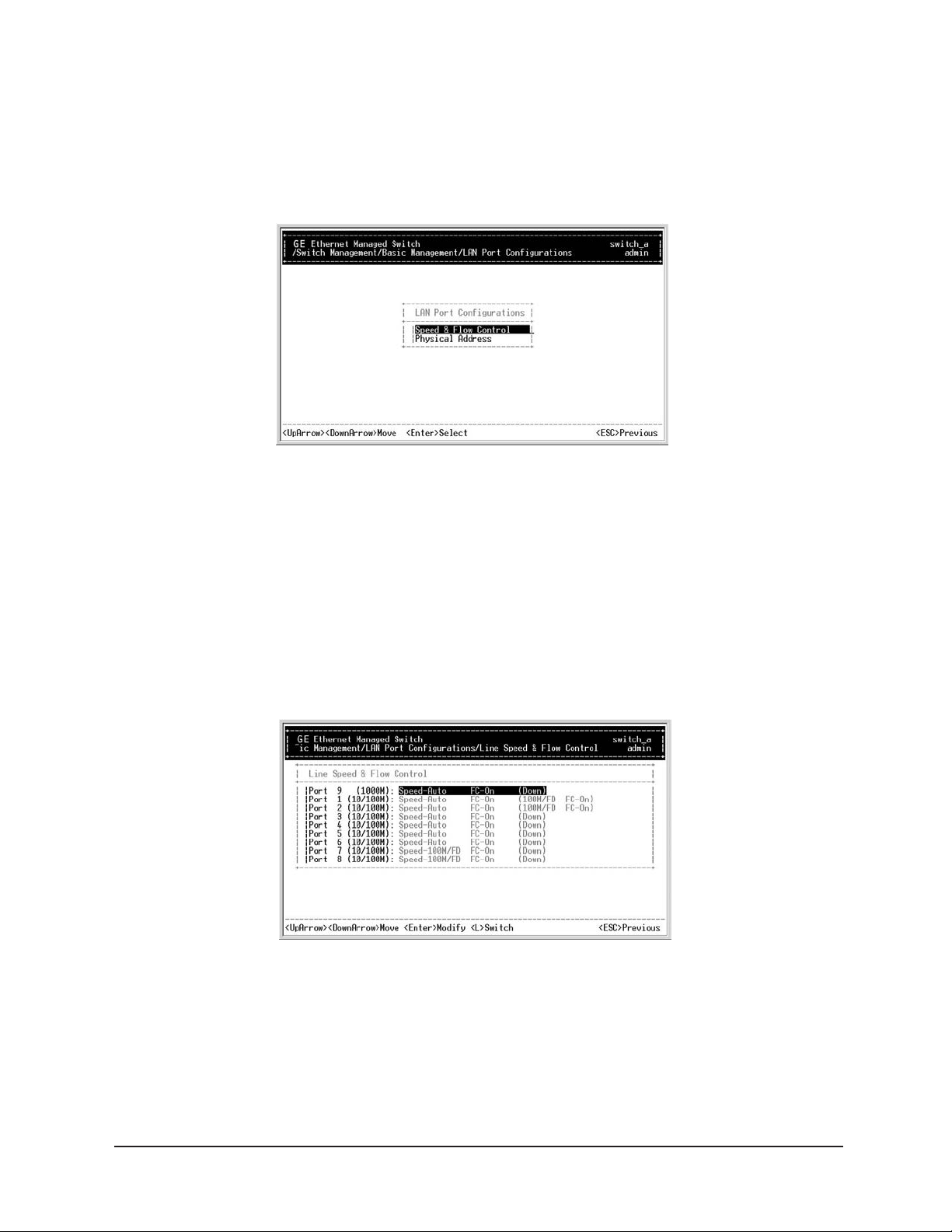
LAN Port Configurations
Step 1:
Highlight LAN Port from [Basic Management] screen, and press <enter>.
Step 2: Speed & Flow Control
Speed & Flow Control
is highlighted. Press <enter> if you want to set speed or flow
control on port.
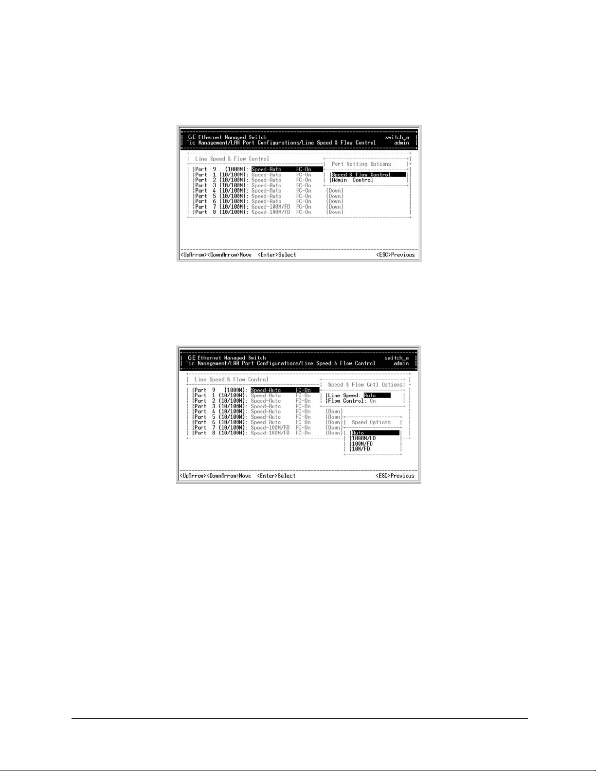
Step 3:
Highlight All Ports and press <enter> to configure at one time.
Or move to highlight each port and press <enter> to configure individually.
’s Manual 28
User
Page 33
Manageable 8/9-Port Switch
Step 4:
Port Setting Options
screen appears. Highlight Speed & Flow Control,
and press <enter>.
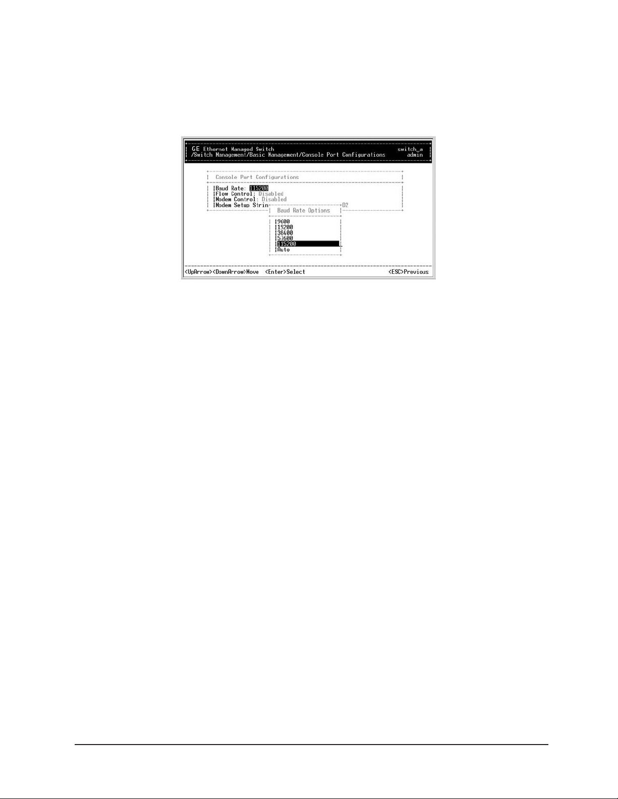
Step 5: Line Speed
For Line Speed, move to highlight a desired setting from Speed Options,
and press <enter>.
Note: In the Speed Options, HD denotes half-duplex and FD denotes full-duplex.
Step 6:
Press <esc> to previous screen. Highlight Flow Control, and press <enter>.
Step 7: Flow Control
For Flow Control, move to highlight a desired setting from Flow Cntl Options,
and press <enter>.
User’s Manual 29
Page 34

Step 8:
Press <esc> to a previous screen as shown in Step 3.
Step 9: Admin. Control
Highlight All Ports and press <enter> to configure at one time.
Or move to highlight each port and press
<enter> to configure individually.
Manageable 8/9-Port Switch
Step 10:
For Admin Control, move to highlight Up or Down from Admin Status Options.
Step 11:
The port is set as Admin Down to stop TX/RX transmission. To allow transmission on the
port, move to highlight Up from the options in Step 10.
Step 12: Physical Port Address
Press <esc> to a previous screen as shown in Step 1.
Step 13:
Move to highlight Physical Address to view physical port address.
Step 14: Return to Basic Management
Press <esc> to return to [Basic Management] screen when completed.
User’s Manual 30
Page 35
Manageable 8/9-Port Switch
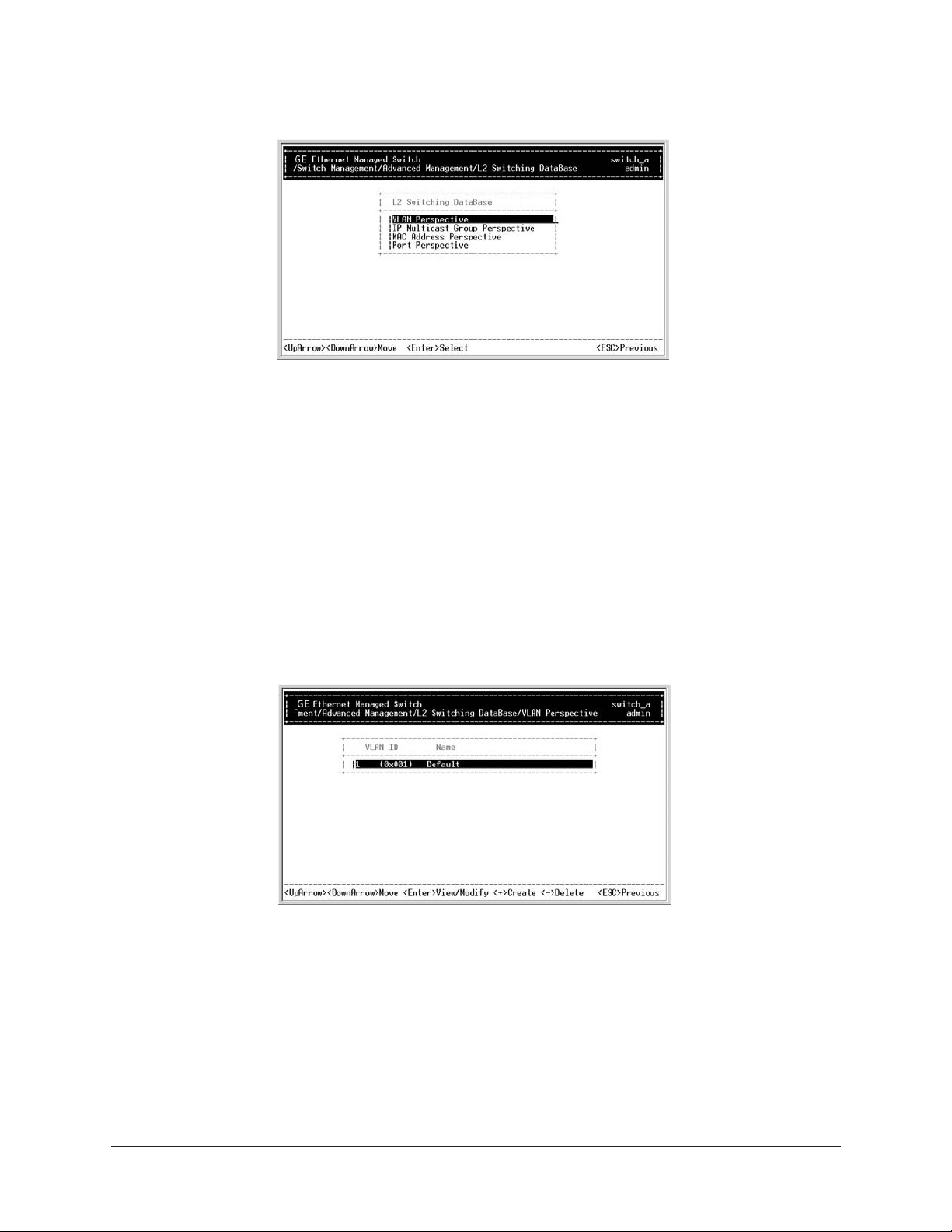
Console Port Configurations
Step 1:
Move to highlight Console Port from [Basic Management] screen.
Step 2: Baud Rate
Baud Rate is highlighted. Press <enter> if you want to change the current
console baud rate.
Step 3: Flow Control
Press <esc> to return to [Basic Management] screen when completed.
Step 4: Modem Control
Step 5: Modem Setup String
Not Supported.
Step 6: Return to Basic Management
Press <esc> to return to [Basic Management] screen when completed.
User’s Manual 31
Page 36

Alarm Configurations
Step 1:
Move to highlight Alarm from [Basic Management] screen.
Step 2:
Set optical ports Loss of Signal.
Manageable 8/9-Port Switch
Step 3:
Highlight desired function.
’s Manual
User
32
Page 37

Manageable 8/9-Port Switch
PERFORMING ADVANCED MANAGEMENT ACTIVITIES
Advanced management activities consist of L2 Switching Database/ IP Networking/
Bridging/ Static Filtering/ Spanning Tree/ SNMP/ Other Protocols/ Port Trunking/
Port Mirroring/ File Transfer.
To Perform Advanced Management Activities
Step 1:
Highlight [Advanced Management] from Switch Management screen, and press <enter>.
The [Advanced Management] screen appears:
Step 2:
Move to highlight a desired option and press <enter>. Or press <esc> to exit.
L2 Switching DataBase
View and change VLAN, MAC address, IP multicast group, and port perspectives.
IP Networking
View and change IP settings and ping settings.
Bridging
View and change aging period for MAC address and flood limit for all ports.
Static Filtering
View/add/delete/search all source/destination MAC addresses to be filtered.
Rapid Spanning Tree
View and change spanning tree configurations, ports states, path costs, and port priorities.
SNMP
View and change the SNMP configuration.
Port Mirroring
Mirror one port to Port 1.
Other Protocols
View and change GVRP and IGMP settings.
Link Aggregation
Assign a range of ports to trunking groups.
QoS Set Up
File Transfer
Send files using the TFTP or Kermit protocol.
User’s Manual 33
Page 38
Manageable 8/9-Port Switch
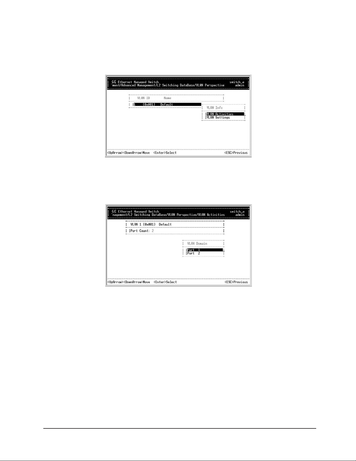
L2 Switching DataBase
Step 1: VLAN Perspective
Highlight L2 Switching Database from [Advanced Management] screen,
and press
<enter>.
Step 2:
The VLAN Perspective is highlighted. Press <enter> to view VLAN info of the default VLAN
or if you want to obtain a VLAN perspective instead of the default VLAN.
Note: Default VLAN:
The IEEE802.1Q standard defines VLAN ID #1 as the default VLAN.
The default VLAN includes all the ports as the factory default.
Step 3: Create VLAN
Press <+> on keypad to enter New VLAN Settings.
Enter new VLAN ID and VLAN name.
Note: "Remote" is appended to the VLAN ID automatically if the VLAN is learned
from a remote switch.
’s Manual 34
User
Page 39
Manageable 8/9-Port Switch
Step 4:
Press <esc> and the following screen appears. Press <+> to add new switch ports to the
newly created VLAN.
Step 5:
Move to highlight a suitable option from Port Options and press <enter>,
e.g. Untagged Ports.
Step 6:
From Select Untagged Ports, press <enter> to select All Ports or move to highlight each
port individually and press
Forbidden Ports in
Step 5.
<enter>. Similar procedure when you select Tagged Ports and
Note: If you added untagged ports and want to now add tagged ports or forbidden
ports, or vice versa, repeat Step 5 and Step 6.
User’s Manual 35
Page 40
Manageable 8/9-Port Switch
Step 7:
Press <esc> to a previous screen as shown in Step 2.
Step 8: Delete VLAN
Highlight a VLAN ID and press <-> to delete it.
Note: The default VLAN cannot be deleted.
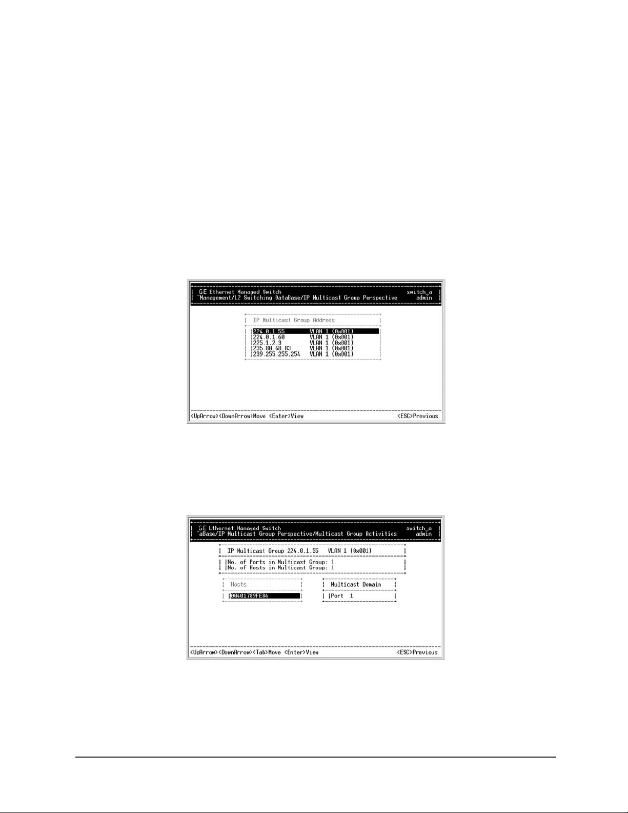
IP Multicast Group Perspective
Step 1:
Move to highlight IP Multicast Group Perspective from L2 Switching Database screen, and
press
<enter>.
Step 2:
Move to highlight an address to view information associated with this IP
multicast group.
User’s Manual 36
Page 41
Manageable 8/9-Port Switch
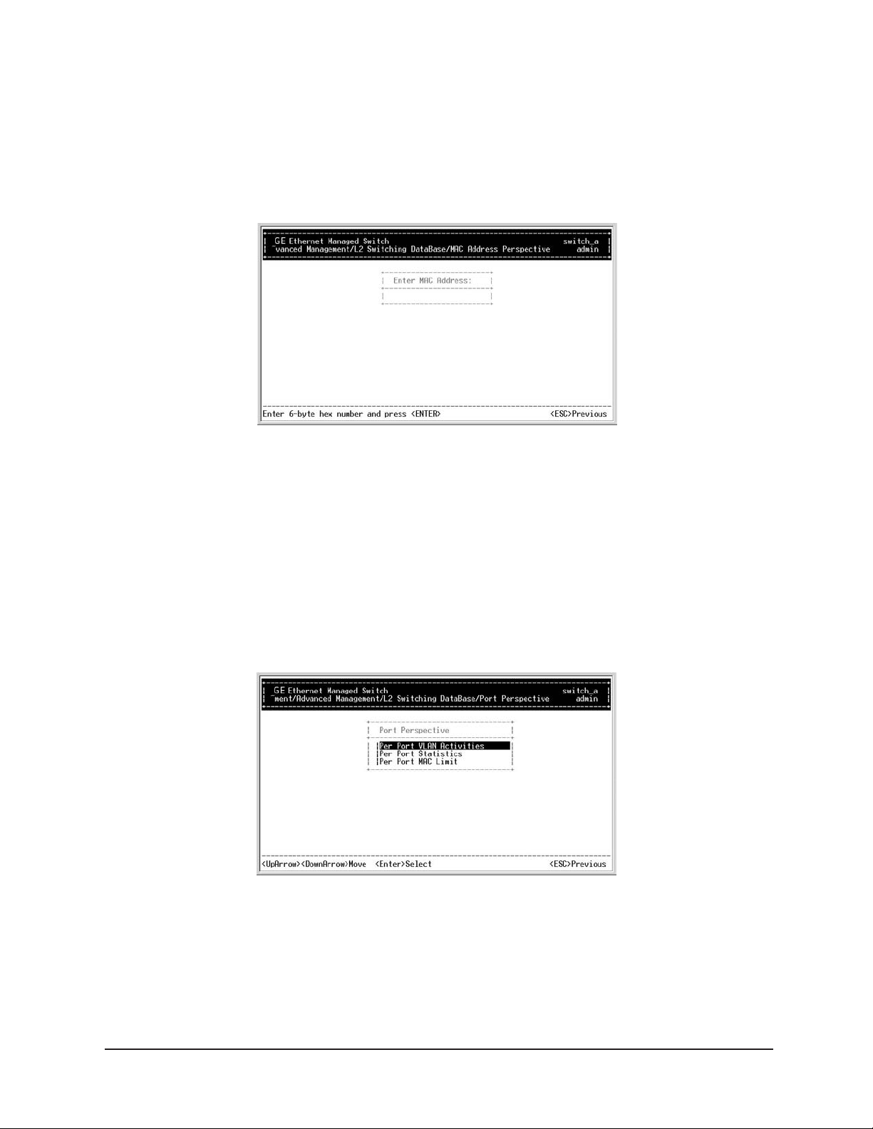
MAC Address Perspective
Step 1:
Move to highlight MAC Address Perspective from L2 Switching Database screen,
and press
<enter>.
Step 2:
Enter a MAC address to view characteristics information, corresponding VLAN’s,
and corresponding ports in the switching database.
t Perspective
Por
Step 1:
Move to highlight Port Perspective from L2 Switching Database screen,
and press
<enter>. You can view VLAN activities and RMON statistics here.
User
’s Manual
37
Page 42
Manageable 8/9-Port Switch
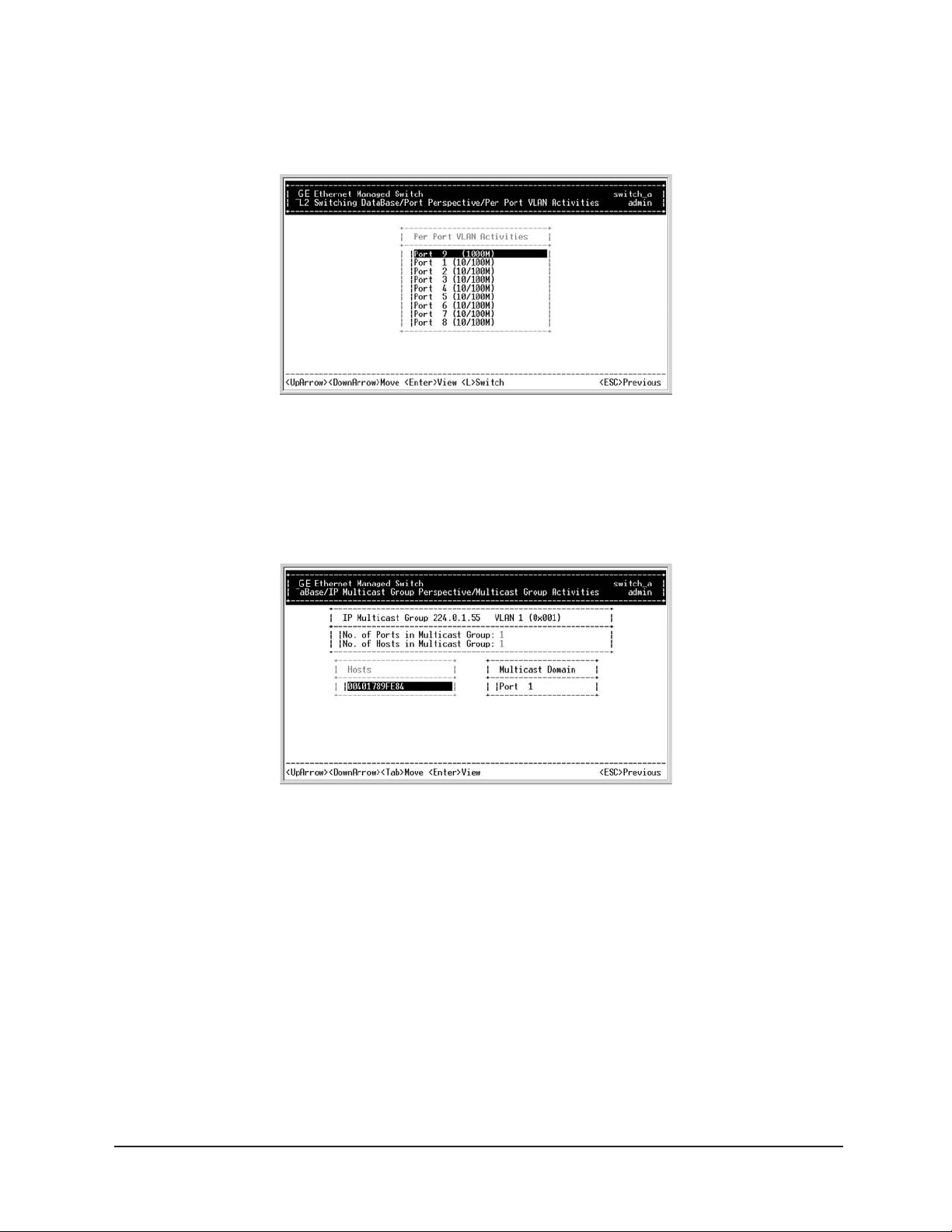
Step 2: Per Port VLAN Activities
Per Port VLAN Activities
is highlighted. Press <enter>.
Step 3:
Move to highlight a port and press <enter>. Example: select Port 1 to view
corresponding VLAN Activities.
Step 4:
View or search by MAC address individually.
Step 5:
Press <esc> to return to a previous screen as shown in Step 1.
’s Manual 38
User
Page 43
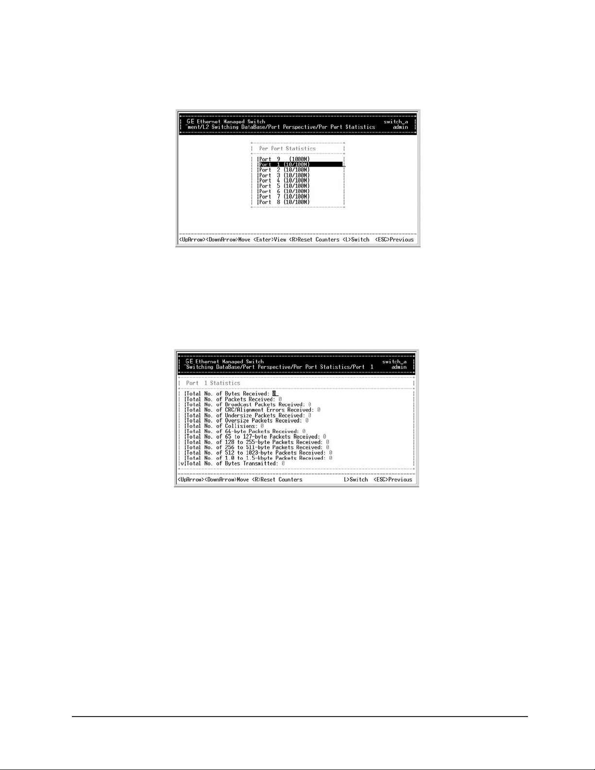
Step 6: Per Port Statistics
Move to highlight Per Port Statistics and press <enter>.
Step 7:
e to highlight a port and press
Mov
VLAN Activities. Press
[R] to reset counter for this port.
<ent
er>.
Example: select Port 1 to view corr
Manageable 8/9-Port Switch
esponding
User
’s Manual
39
Page 44
Manageable 8/9-Port Switch
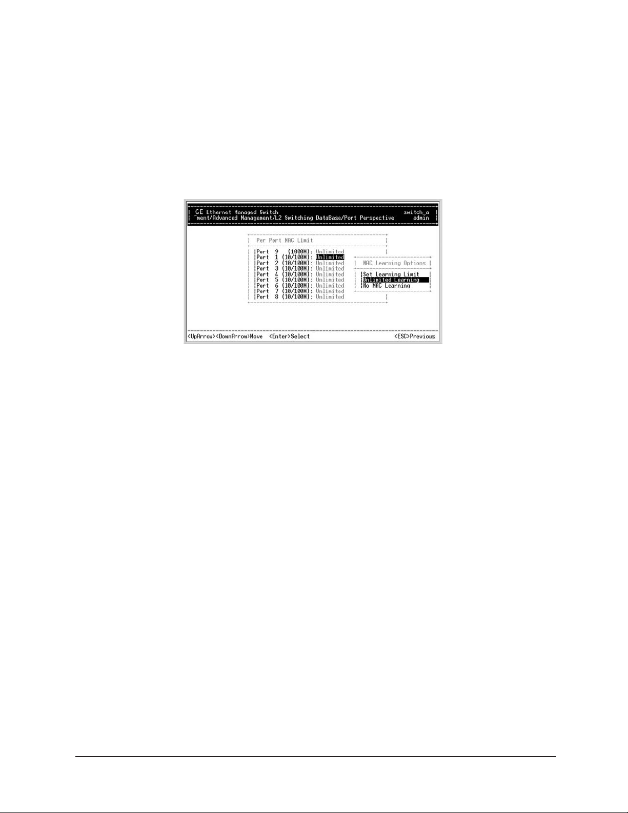
Step 8: Per Port MAC Unit
Move to highlight Per Port Priority and press <enter>.
Step 9:
Move to highlight a port and press <enter>. Example: select Port 1 to view
corresponding priority level.
User
’s Manual
40
Page 45
Manageable 8/9-Port Switch
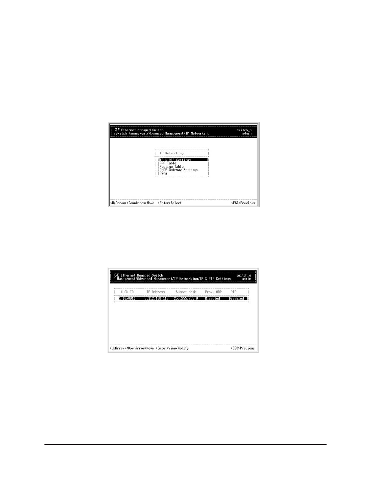
IP Networking
Step 1:
Move to highlight IP Networking from [Advanced Management]
screen, and press <enter>.
Step 2: IP & RIP Settings
Highlight IP & RIP Settings from IP Networking, and press <enter>.
Step 3:
The screen shows a list of VLAN IDs, IP addresses, subnet masks, proxy ARPs, and RIPs
currently defined.
User’s Manual 41
Page 46
Manageable 8/9-Port Switch
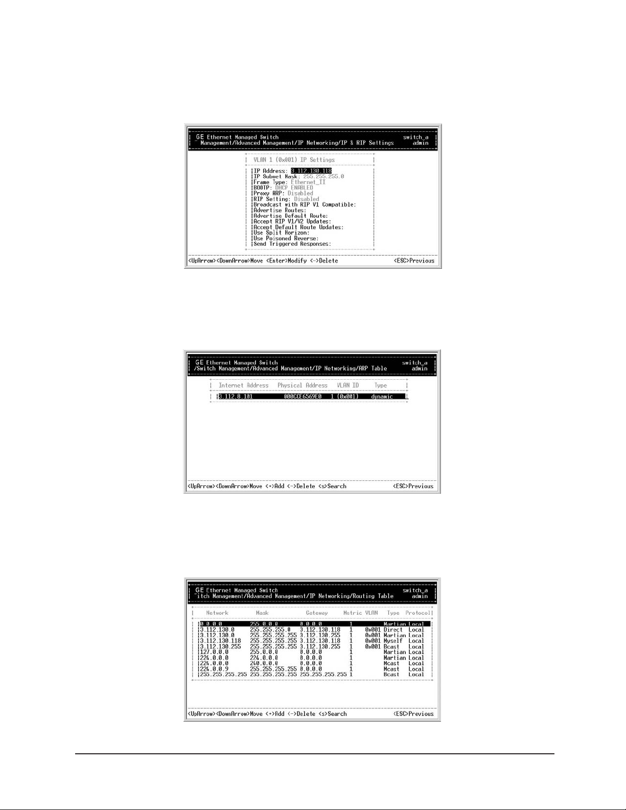
Step 4:
Move to highlight the row that contains the parameters you want to change,
and press
<enter>.
ARP Table
Step 1:
Highlight ARP Table from IP Networking, and press <enter>.
Routing Table
Step 1:
Highlight Routing Table from IP Networking, and press <enter>.
’s Manual 42
User
Page 47
Manageable 8/9-Port Switch
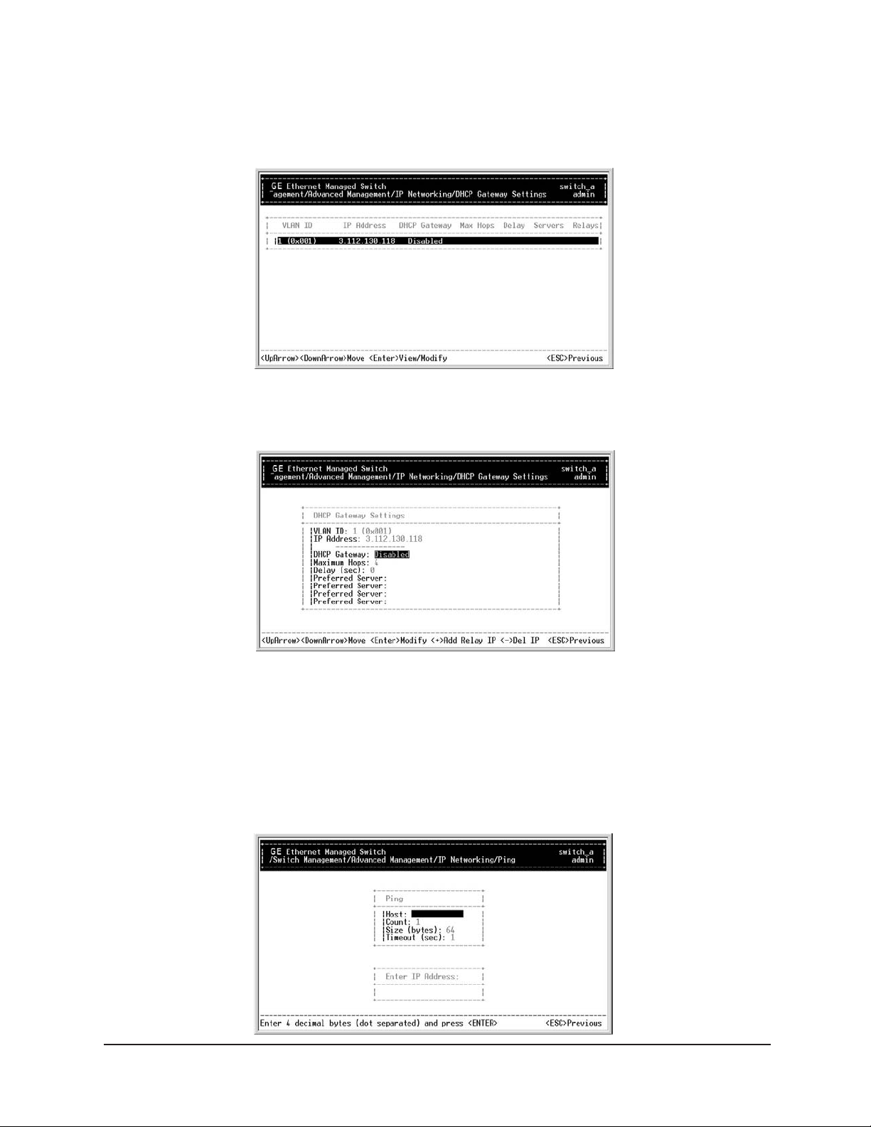
DHCP Gateway
Step 1:
Highlight DHCP Gateway from IP Networking, and press <enter>.
Step 2:
Select VLAN, and press <enter>.
Step 3:
Highlight DHCP Gateway for Enabling or Disabling function.
Ping Settings
Step 1:
Move to highlight Ping from IP Networking, and press <enter>.
User’s Manual 43
Page 48

Manageable 8/9-Port Switch
Step 2: Host
Move to highlight Host, and press <enter>.
Step 3:
Enter 4 decimal bytes (dot separated) as the IP address to ping.
Step 4: Count
Move to highlight Count, and press <enter>.
Step 5:
Specify a packet count number from 1 to 999, or type 0 for an infinite packet count,
and press
<enter>.
Step 6: Size (bytes)
Move to highlight Size, and press <enter>.
Step 7:
Specify a packet size from 0-1500, and press <enter>.
Step 8: Timeout (sec)
Move to highlight Timeout, and press <enter>.
Step 9:
Specify a timeout value from 1-999, and press <enter>.
Step 10:
Press <esc> to start to ping when completed with the ping parameters.
User’s Manual 44
Page 49

Manageable 8/9-Port Switch
Bridging
Step 1:
Move to highlight Bridging from [Advanced Management] screen, and press <enter>.
Step 2: Aging Time
Move to highlight Aging Time, and press <enter>. Enter a decimal number as bridge
aging period in seconds or, enter 0 for no aging.
Step 3: Flood Limits for all Ports
Move to highlight Flood Limit for All Ports, and press <enter>. Enter a decimal
number as flood limit in packets per second or, enter 0 for no limit.
Static Filtering
Step 1:
Move to highlight Static Filtering from [Advanced Management] screen,
and press
<enter>.
’s Manual 45
User
Page 50

Manageable 8/9-Port Switch
Step 2: Source/Destination MAC Address Out-Filters
Move to highlight Source MAC Addresses or Destination MAC Addresses for static filtering,
and press
<enter>.
Source Filter
Destination Filter
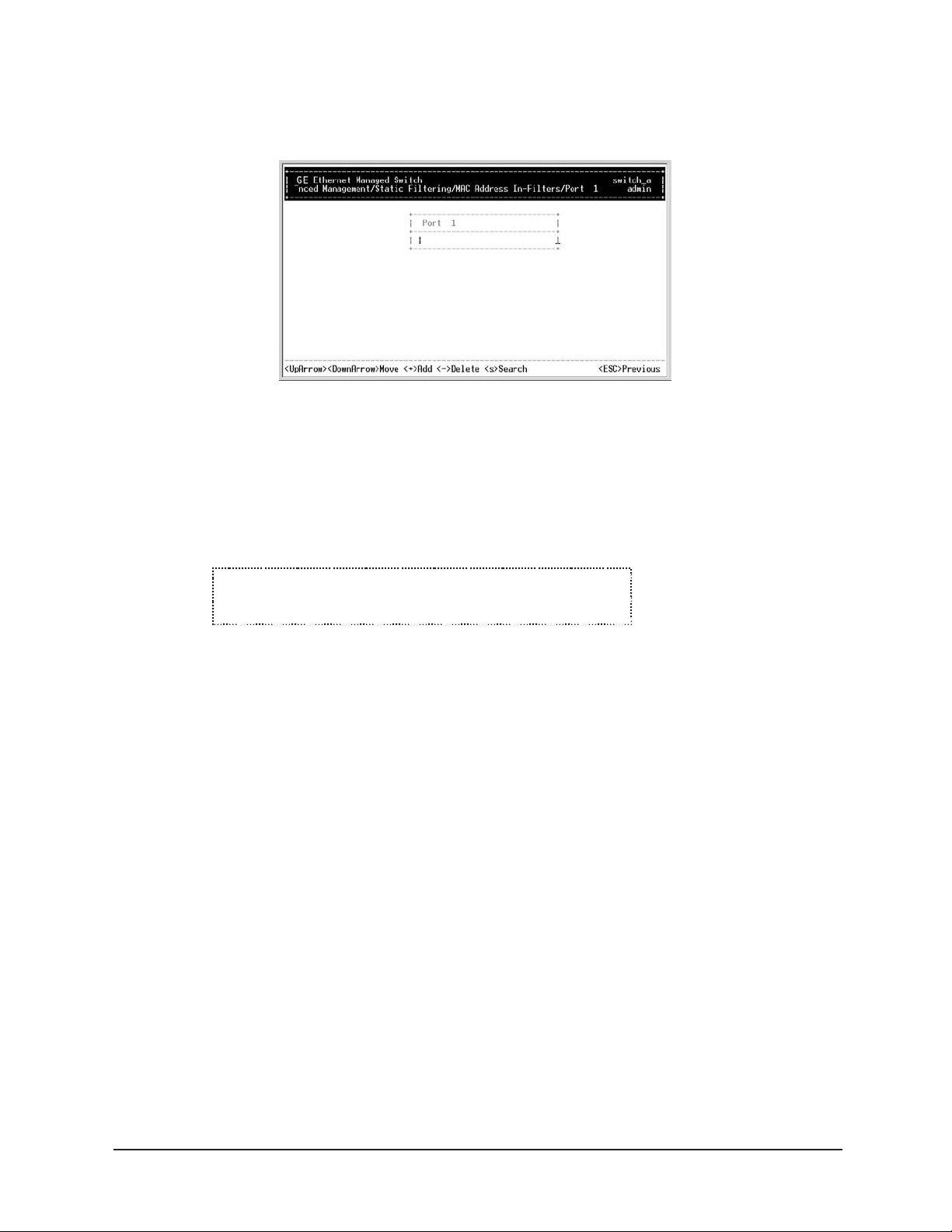
MAC Address in Filters
Step 3:
Move to highlight MAC Address Filters from Static Filtering, and press <enter>.
’s Manual 46
User
Page 51
Manageable 8/9-Port Switch
* No prec autionary message app ears before y ou delet e a specific MAC
address from being filtered.
* Be sure you want to dele te it bef ore doing so.
MAC Address in Filters
Step 4: Add/Delete/Search
Press [+] on keypad to add a specific MAC address to be filtered. Press [-] to delete a specific MAC
address from being filtered. Press
[S] to search through current list of MAC addresses in the static
filtering database. The static filtering database maximum capacity is 64.
Caution:
’s Manual 47
User
Page 52
Manageable 8/9-Port Switch
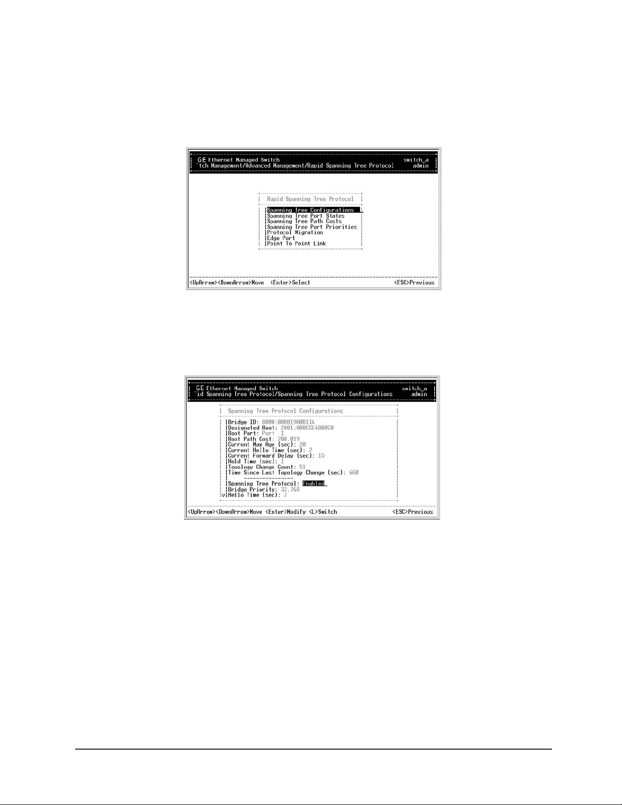
Rapid Spanning Tree Functions
Step 1:
Move to highlight Rapid Spanning Tree from [Advanced Management] screen, and press <enter>.
Step 2: Spanning Tree Configurations
Move to highlight Spanning Tree Configurations if you want to change Spanning Tree Protocol
Configurations.
Step 3: Spanning Tree Protocol
Press <enter> to enter Spanning Tree Options. Decide to have it Disabled or Enabled.
Step 4: Bridge Priority
Move to highlight Bridge Priority, and press <enter>. Type a decimal number for the bridge
priority and press
<enter>.
Step 5: Hello Time (sec)
Move to highlight Hello Time, and press <enter>. Type a decimal number for the hello time, and
press <enter>.
User
’s Manual 48
Page 53

Manageable 8/9-Port Switch
Step 6: Max Age (sec)
Move to highlight Max Age, and press <enter>. Type a decimal number for the max age.
Step 7: Forward Delay (sec)
Move to highlight Forward Delay, and press <enter>. Type a decimal number for the
forward delay.
Spanning Tree Port States
Step 1:
Move to highlight Spanning Tree Port States if you want to change per port administration status,
and press
<enter>.
Step 2:
Move to highlight a port if you want to change its administration status, and press <enter>.
Disabled (Link Down)
denotes Admin Status Up without a link. Forwarding denotes
Admin Status Up with a link. Admin Status Down denotes no TX/RX transmission allowed.
Admin Status Up denotes TX/RX transmission allowed.
Spanning Tree Path Costs
Step 1:
Move to highlight Spanning Tree Path Costs if you want to change the path cost,
and press
<enter>.
’s Manual 49
User
Page 54

Manageable 8/9-Port Switch
Spanning Tree Port Priorities
Step 1:
Move to highlight Spanning Tree Port Priorities if you want to change the priority level per port,
and press
<enter>.
Step 2:
Move to highlight All Ports or each port individually, and press <enter>. For new priority value,
type a decimal number from 0-255, and press
likelihood of becoming a Root por
t.
<enter>. A low value gives the port a greater
Protocol Migration
’s Manual 50
User
Page 55

Edge Port
Point-to-Point Link
Manageable 8/9-Port Switch
SNMP Functions
Step 1:
Move to highlight SNMP from [Advanced Management] screen, and press <enter>.
Step 2: SNMP Options
Move to highlight SNMP, and press <enter>. Decide to have it Disabled or Enabled.
User’s Manual 51
Page 56

Manageable 8/9-Port Switch
Step 3: Get Community Name
Move to highlight Get Community Name, and press <enter>.
Enter text and press <enter>.
Step 4: Set Community Name
Move to highlight Set Community Name, and press <enter>. Enter text and press <enter>.
Step 5: Trap Community Name
Move to highlight Trap Community Name 1 and press <enter>. Enter text and press <enter>.
Repeat to specify up to three more trap community names.
Step 6: Trap Host IP Address
Move to highlight Trap Host 1 IP Address, and press <enter>. Type an IP address for trap host 1
and press
<enter>. Repeat to specify up to two more trap host IP addresses.
Step 7: Cold Start Trap
Move to highlight Cold Start Trap, and press <enter>. Decide to have it Disabled or Enabled.
Step 8: Warm Start Trap
Move to highlight Warm Start Trap, and press <enter>. Decide to have it Disabled or Enabled.
Step 9: Link Down Trap
Move to highlight Link Down Trap, and press <enter>. Decide to have it Disabled or Enabled.
Step 10: Link Up Trap
Move to highlight Link Up Trap, and press <enter>. Decide to have it Disabled or Enabled.
Step 11: Authentication Failure Trap
Move to highlight Authentication Failure Trap, and press <enter>.
Decide to have it Disabled or Enabled.
Step 12: Rising Alarm Trap
Move to highlight Rising Alarm Trap, and press <enter>.
Decide to have it Disabled or Enabled.
Step 13: Falling Alarm Trap
Move to highlight Falling Alarm Trap, and press <enter>.
Decide to have it Disabled or Enabled.
Step 14: Topology Change Trap
Move to highlight Topology Change Trap, and press <enter>.
Decide to have it Disabled or Enabled.
User
’s Manual
52
Page 57

Manageable 8/9-Port Switch
Other Protocols
Step 1:
Move to highlight Other Protocols from [Advanced Management] screen, and press <enter>.
Step 2: GVRP
Move to highlight GVRP, and press <enter>. Decide to have it Disabled or Enabled.
Step 3: IGMP
Move to highlight IGMP, and press <enter>. Decide to have it Disabled or set in either Passive or
Active mode.
Link Aggregation
Step 1:
Move to highlight Link Aggregation from [Advanced Management] screen,
and press
<enter>.
User’s Manual 53
Page 58
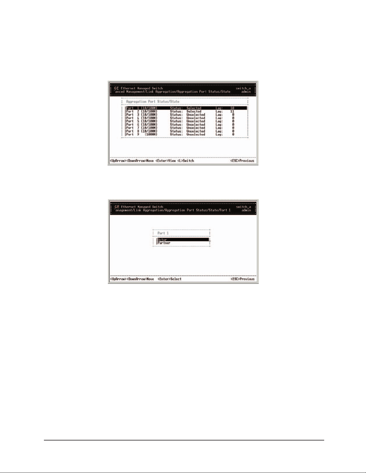
Aggregation Port Status
Step 2:
Move to highlight Aggregation Port Status, and press <enter>.
Step 3:
Select Actor or Partner for the Port selected.
Manageable 8/9-Port Switch
’s Manual 54
User
Page 59
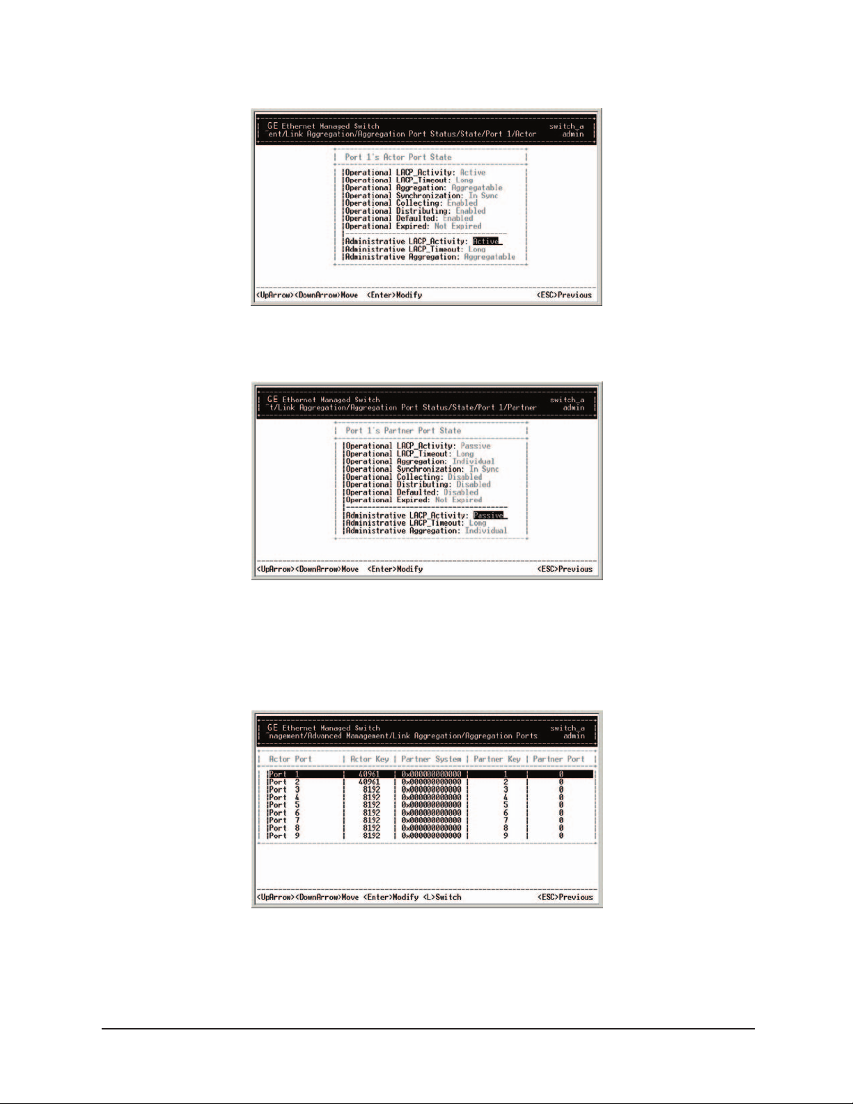
Actor Screen
Partner Screen
Manageable 8/9-Port Switch
Aggregation Port Settings
Step 4:
Move to highlight Aggregation Port Settings, and press <enter>.
User’s Manual 55
Page 60
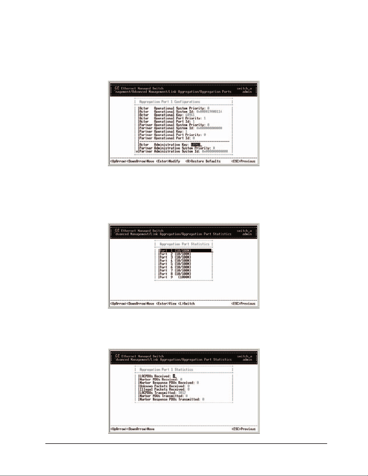
Aggregation Port Settings
Step 5:
Select desired Port.
Aggregation Port Statistics
Manageable 8/9-Port Switch
Step 6:
Move to highlight Aggregation Port Statistics, and press <enter>.
Step 7:
Select desired Port.
User’s Manual 56
Page 61
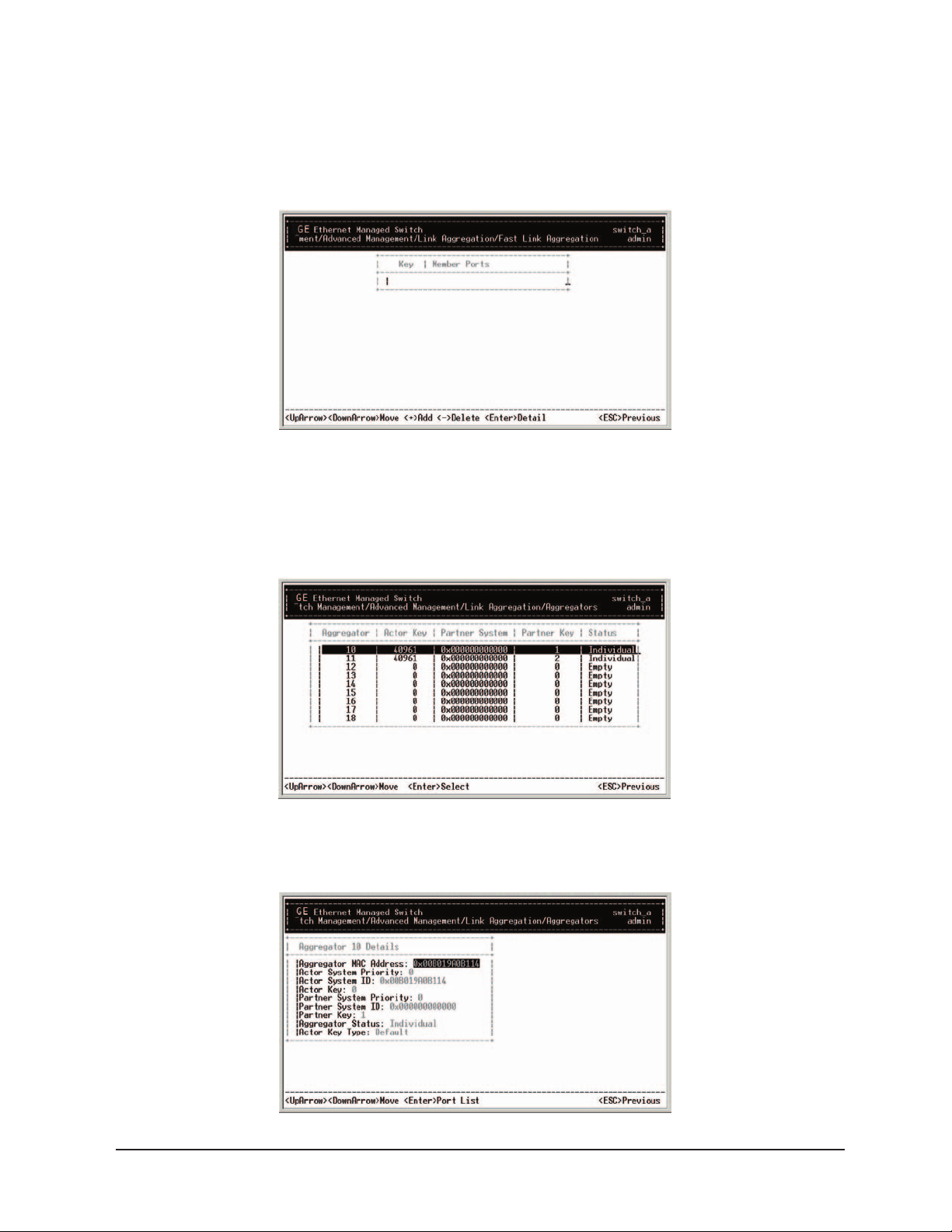
Fast Link Aggregation
Step 8:
Move to highlight Fast Link Aggregation, and press <enter>.
IEEE802.3 Aggregation
Manageable 8/9-Port Switch
Step 9:
Move to highlight IEEE802.3 Aggregation, and press <enter>.
Step 10:
Select desired Aggregator.
’s Manual 57
User
Page 62
Manageable 8/9-Port Switch
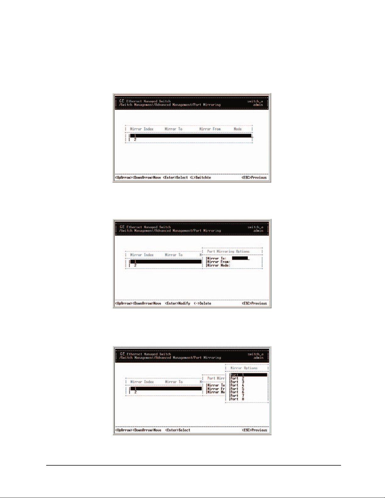
Port Mirroring
Step 1:
Move to highlight Port Mirroring from [Advanced Management] screen, and press <enter>.
You can mirror one port to Port 1.
Step 2:
Press <enter> to enter Port Mirroring Options.
Step 3: Mirror Fr
om
Press <enter> to enter Mirror From Options, listing the ports that can be mirrored from.
User’s Manual 58
Page 63
Manageable 8/9-Port Switch
Step 4:
Move to highlight the port you want to mirror from and press <enter>.
Step 5: Mirror Mode
Move to select Mirror Mode. From Mode Options, decide whether the port to be mirrored
from will be receiving or transmitting.
Step 6:
Press <esc> when completed.
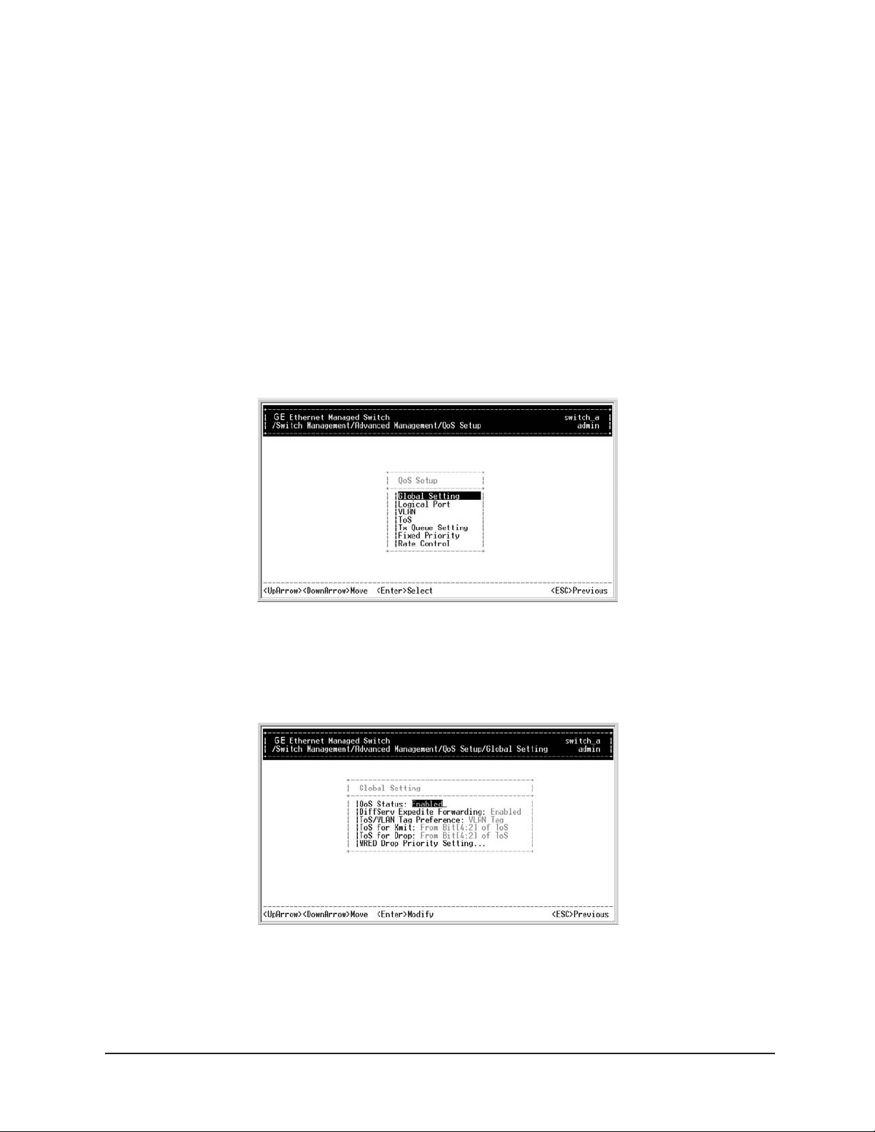
Quality of Service (QoS)
Step 1:
Move to highlight QoS Setup from [Advanced Management] screen, and press <enter>.
Global Setting
Step 2:
Move to highlight Global Setting, and press <enter>.
’s Manual 59
User
Page 64

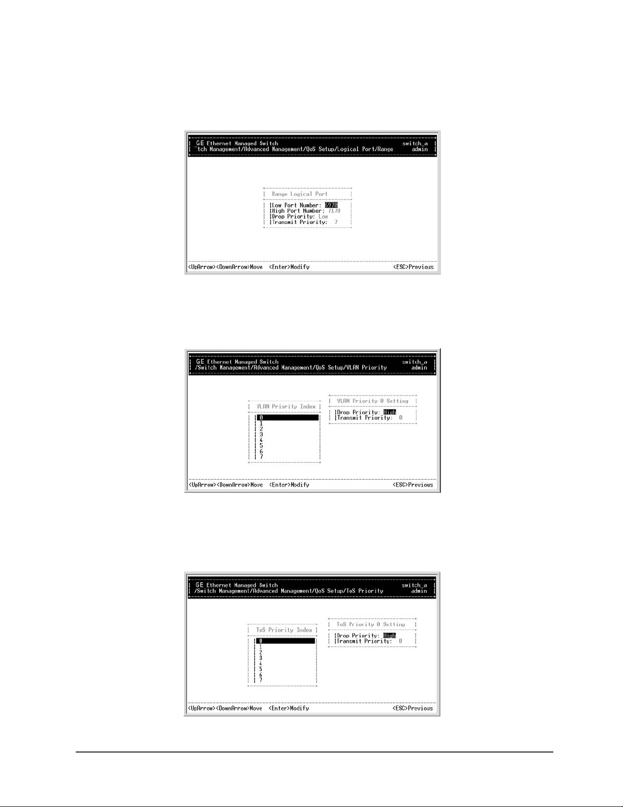
Logical Port
Step 3:
Move to highlight Logical Port, and press <enter>.
Step 4:
Move to highlight User Defined Port.
Manageable 8/9-Port Switch
Step 5:
Select Port to be Defined.
Step 6:
Move to highlight Well-Known Port.
User’s Manual 60
Page 65
Step 7:
Select Port to be Defined.
Step 8: Move to highlight Range Port.
VLAN
Step 1:
Move to highlight VLAN from QoS Setup, and press <enter>.
Step 2: Assign desired port to a VLAN.
Manageable 8/9-Port Switch
ToS
Step 1: Move to highlight ToS from QoS Setup, and press <enter>.
Step 2: Highlight desired port to be set.
’s Manual
User
61
Page 66
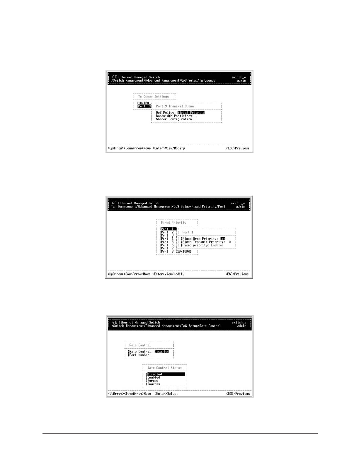
Tx Queue Setting
Step 1:
Step 2:
Move to highlight Tx Queue Setting from QoS Setup, and press <enter>.
Set Queue for optional Port 9.
Fixed Priority
Manageable 8/9-Port Switch
Step 1:
Step 2:
Move to highlight Fixed Priority from QoS Setup, and press <enter>.
Select desired Port.
Rate Control
Step 1: Move to highlight Rate Control from QoS Setup, and press <enter>.
User
’s Manual
62
Page 67
Manageable 8/9-Port Switch
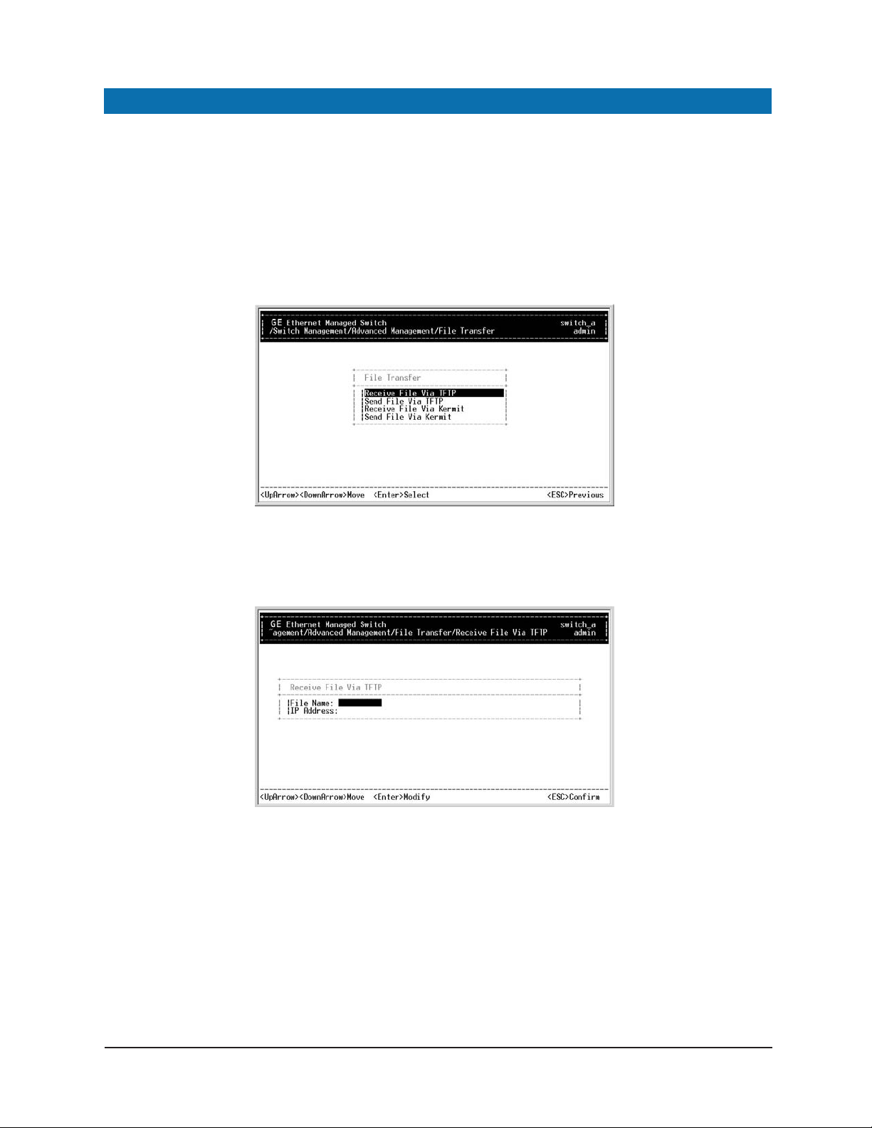
SENDING AND RECEIVING FILES
The TFTP protocol is used to download upgraded software to the switch.
A VLAN with the proper IP address and routing path to the TFTP server must be configured
for the switch to access the specified TFTP server.
Step 1:
Move to highlight File Transfer from [Advanced Management] screen, and press <enter>.
Step 2: Receive File Via TFTP
Move to highlight Receive File Via TFTP and press <enter>.
Step 3:
If the default File Name is not the one you intend to receive, press <enter>.
Type the name of the file you intend to receive and press
<enter>.
Step 4:
Move to highlight IP Address and press <enter>.
Type the IP address from where the file will be obtained.
User’s Manual 63
Page 68
Manageable 8/9-Port Switch
Step 5:
Press <esc> when completed.
Step 6:
A dialog box appears to ask if you want to transfer file now. Highlight [Yes] and
press
Press
<enter> to start file transfer, or move to highlight [No] and press <enter> to deny it.
<esc> to exit.
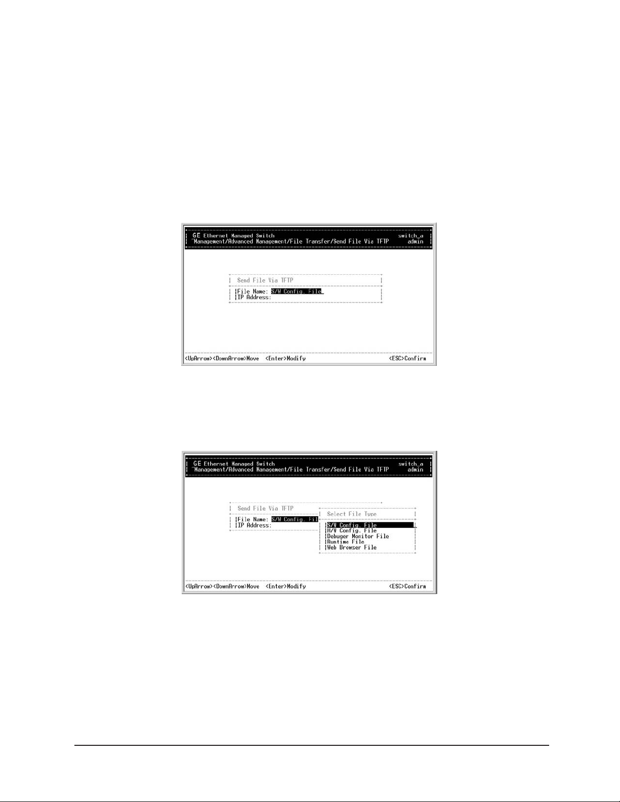
Step 7: Send File Via TFTP
Move to highlight Send File Via TFTP, and press <enter>.
Step 8:
If the default File Type is not the one you intend to send, press <enter>.
Select the file type you intend to send and press <enter>.
Step 9:
Repeat Step 4-6.
User
’s Manual
64
Page 69

Manageable 8/9-Port Switch
Logout
To log out, highlight Logout from [Switch Management] screen, and press <enter>.
Please remember to save settings you have changed before you log out.
Save Settings
To save the current settings and remain in the configuration program, highlight Save Settings from
[Switch Management], and press <enter>.
Restore Default Settings
To restore the factory default settings, highlight Restore Default Settings from
[Switch Management], and press <enter>.
The switch will be rebooted after confirming <Yes> as to restore the default settings.
Reboot
To reboot the switch, highlight Reboot from [Switch Management], and press <enter>.
User’s Manual 65
Page 70
Manageable 8/9-Port Switch
WEB-BASED BROWSER MANAGEMENT
The EtherNav” D7600 switch provides a web-based browser interface for configuring and managing the switch. This interface allows you to access the switch using a preferred web browser.
This section describes how to configure the switch using its web-based browser interface.
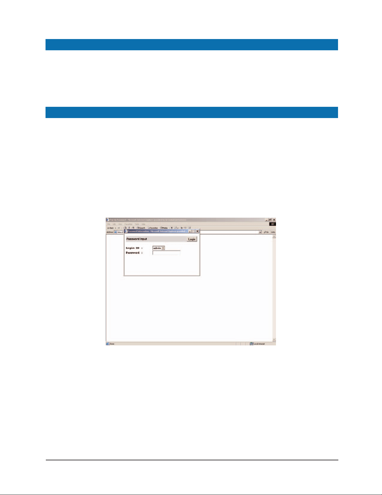
LOGGING ON TO THE SWITCH
Switch IP Address
In your web browser, specify the IP address of the switch.
Login ID
Enter the factory default login ID: admin.
Password
Enter the factory default password (ethernav, click <Login>).
User
’s Manual
66
Page 71

Manageable 8/9-Port Switch
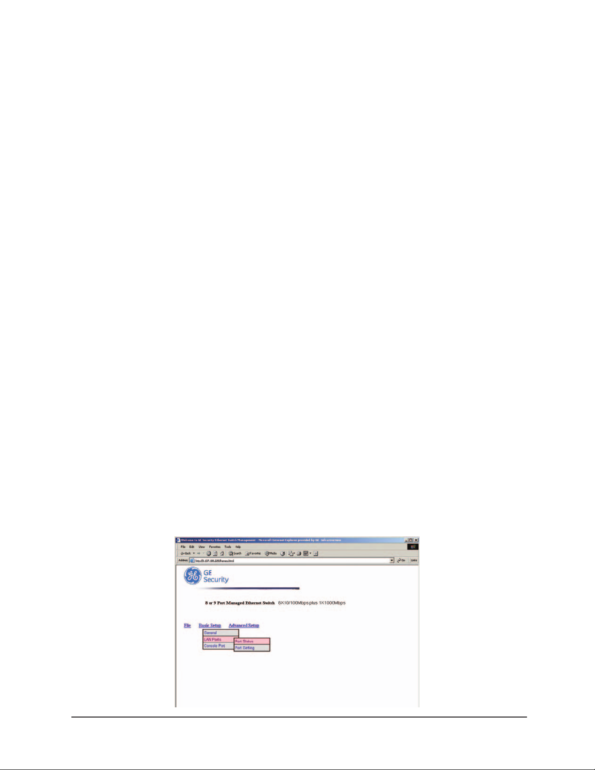
UNDERSTANDING THE BROWSER INTERFACE
The web browser interface provides three point-and-click buttons at the upper field of the screen
for configuring and managing the D-GES7600.
Basic Setup/General parameters appear at the lower field of the screen. These parameters
The
can also be displayed by clicking
Basic Setup button and select General in sub-menu.
File
Save settings configured in the browser interface / download upgraded software via TFTP /
reboot the switch / logout of the browser interface.
Basic Setup
Perform general, LAN port, and console port activities.
Advanced Setup
Perform MAC address management / IP networking / per port statistics / port priority / bridging /
static MAC filters / IP multicast gr
oup / VLAN perspective / spanning tree perspective /
SNMP / other protocols / port trunking / port mirroring.
User
’s Manual
67
Page 72
Manageable 8/9-Port Switch
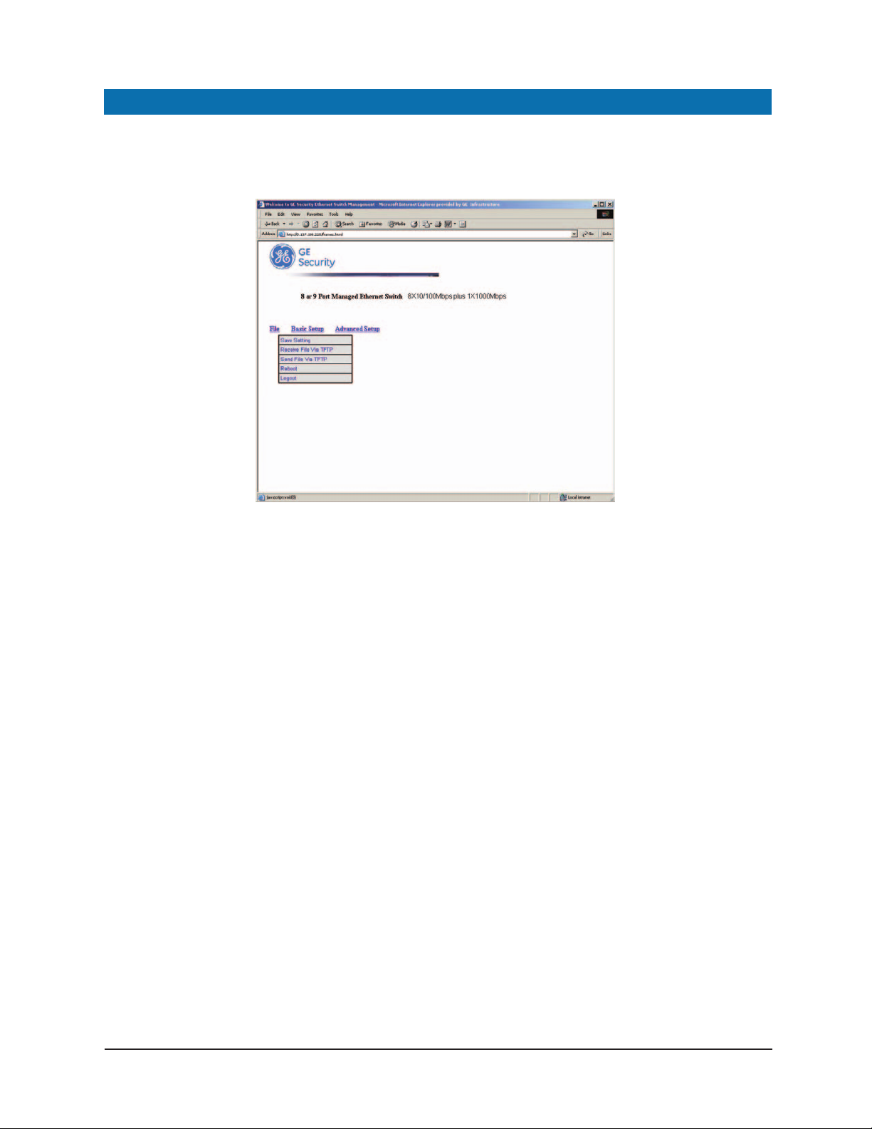
PERFORMING FILE ACTIVITIES
To Perform File Activities:
Click the [File] button at the upper field of the main display, the menu options appear.
Step 1: Saving Setting
Click Saving Setting to save your configuration settings.
Step 2:
When you click it, a message asks "Are you sure you want to save setting? ",
click OK to save it or Cancel to abort it.
Step 1: Receive File Via TFTP
Click Receive File Via TFTP on the [File] display.
Note: The TFTP protocol is used to download upgraded software to the switch.
A VLAN with the proper IP address and routing path to the TFTP server must be
configured for the switch to access the specified TFTP server.
Step 2:
For File Name, type the name of the file you intend to receive.
Step 3:
For IP Address, type the IP address from where the file will be obtained.
Step 4:
Click Receive Now.
User
’s Manual
68
Page 73
Manageable 8/9-Port Switch
Step 1: Reboot
Click Reboot on the [File] display.
Step 2:
When you click it, a message asks "Are you sure you want to save setting?",
OK to save it or Cancel to abort it .
click
Step 1: Logout
Click Logout on the [File] display.
Step 2:
When you click it, a message asks "Are you sure you want to save setting?",
click
OK to save it or Cancel to abort it .
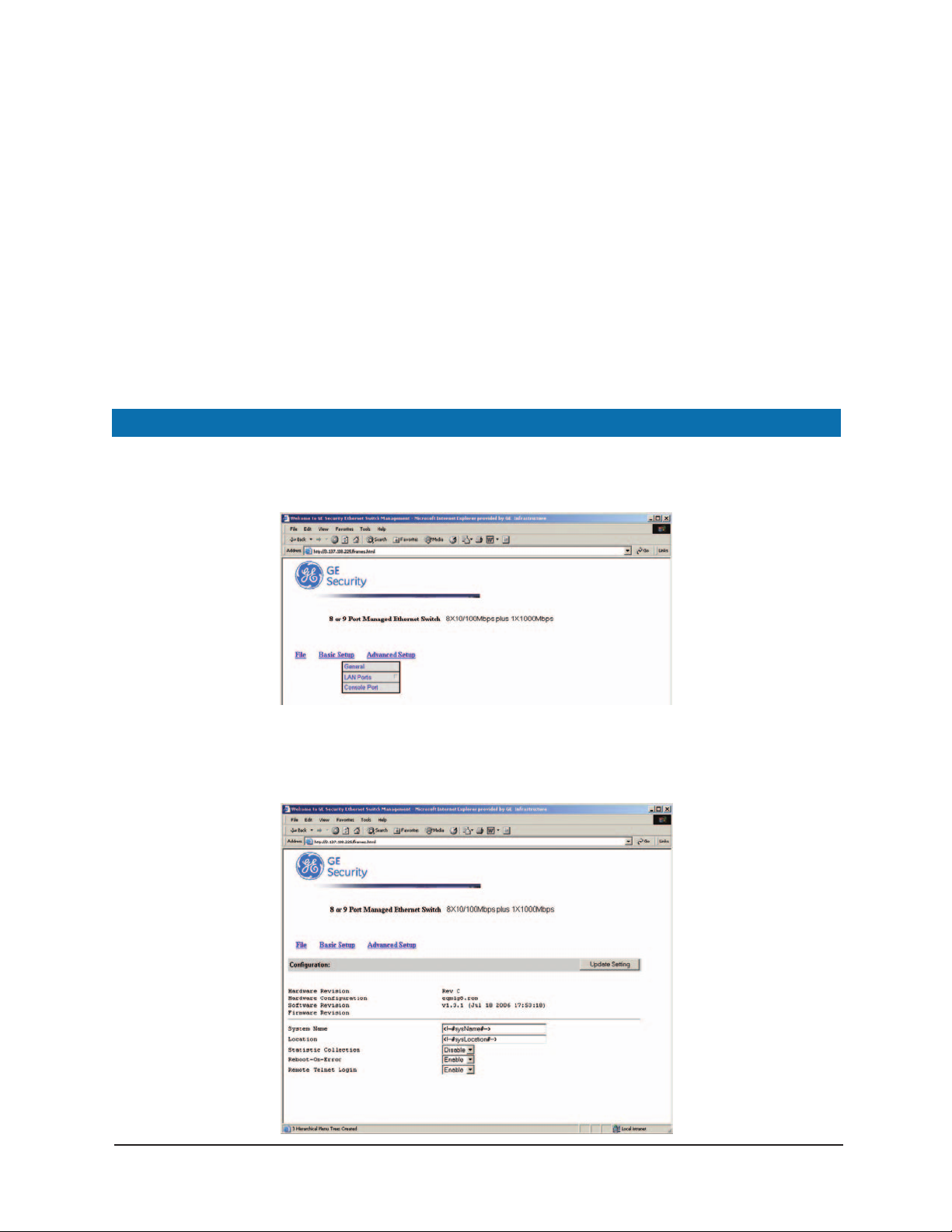
PERFORMING BASIC SETUP ACTIVITIES
To perform Basic Setup Activities:
Click the [Basic Setup] button at the upper field of the main display, the menu options appear.
Step 1: General Management Configuration
Click General and the screen shows’ the Basic Setup/General parameters.
The screen here is the same when you first access the switch browser interface.
’s Manual
User
69
Page 74
Manageable 8/9-Port Switch
Step 2: System Name
Click in System Name text box on the field of Basic Setup/General.
Step 3:
Type a system name if it is blank, or replace the current system name with a new one.
Step 4: Location
Click in Location text box on the field of Basic Setup/General.
Step 5:
Type a location name if it is blank, or replace the current location name with a new one.
Step 6: Statistic Collection
To enable or disable statistics collection at the switch, click the appropriate option from
Statistic Collection drop-down menu.
Step 7: Reboot-On-Error
To allow or prevent the switch from rebooting when a fatal error is detected, click the
appropriate option from
Reboot-On-Error drop-down menu.
Step 8: Remote Telnet Login
To enable or disable access to the switch management program via Telnet
appropriate option from
Remote Telnet Login drop-down menu.
, click the
Step 9:
Click Update Setting. A confirmation window appears.
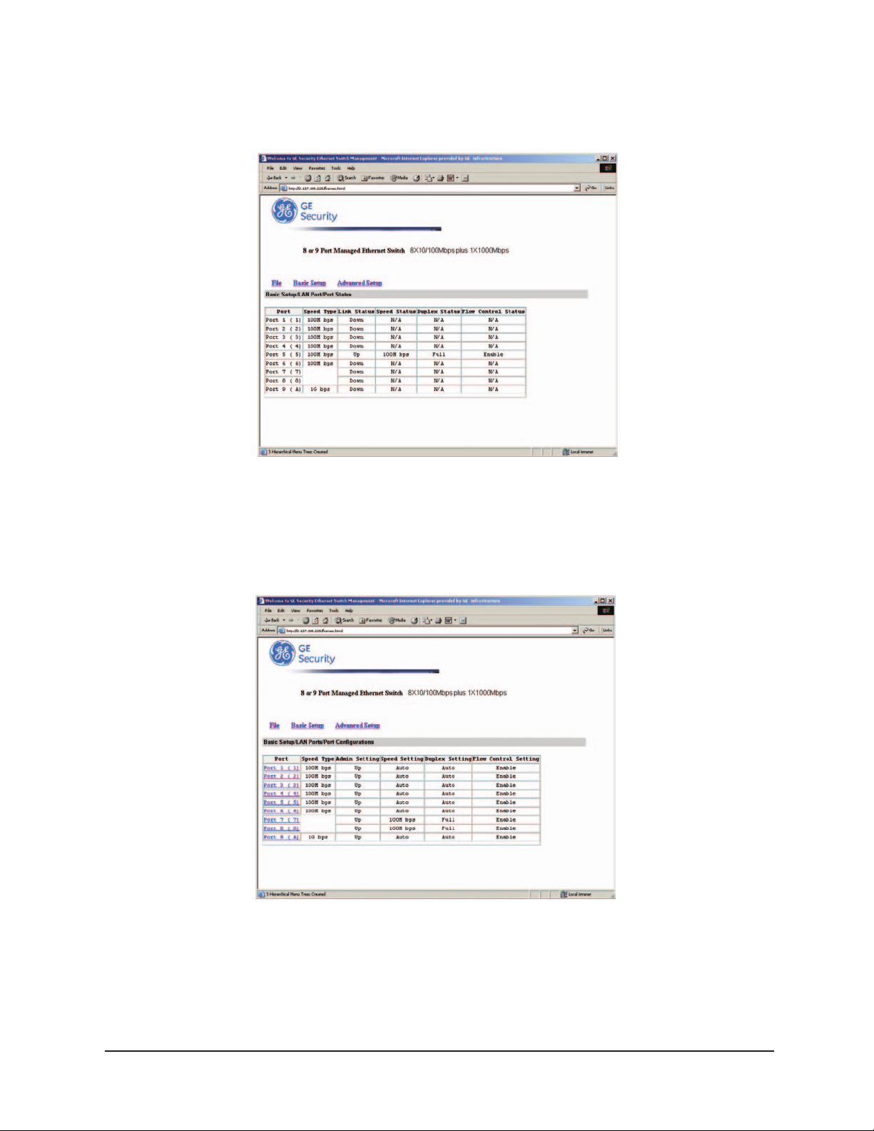
LAN Port Configuration
Step 1:
To access the LAN configuration parameters, click Basic Setup button first and then point
LAN Port and click a suitable option.
to
User
’s Manual
70
Page 75
Manageable 8/9-Port Switch
Step 2: Port Status
Click Port Status to view the line speed and flow control for all ports.
Note: The information displayed automatically updates every 15 seconds, without requiring
you to refresh the window.
Step 3: Por
t Setting
Click Port Setting to access the configuration information for all ports.
Step 4:
In the Port column, click the port you want to configure. E.g. click Port 1.
’s Manual
User
71
Page 76

Manageable 8/9-Port Switch
Step 5:
Click the drop-down menu under Admin Setting, decide to disable or enable it.
Note:
Disable - places the port in DOWN state.
In this state, packets cannot be switches to and from the port.
Enable: places the port in UP state.
In this state, packets can be switched to and from the port.
Step 6:
Click the drop-down menu under Speed/Duplex Options if you want to change
the line speed and duplex settings.
Note:
Auto: allows the switch to automatically ascertain the line speed and duplex mode. All the other
selections force the port to use a specific line speed and duplex mode. ‘HD’ denotes half-duplex
mode; FD denotes full-duplex mode.
Step 7:
Click the drop-down menu under Flow Control Options if you want to configure the flow
control for this port.
Note:
Auto:
allows the switch to automatically decide whether or not to use flow control.
Disable: turns off flow control at all times.
Enable: turns on flow control at all times.
Step 8:
Click Update Setting when completed. A confirmation window appears.
Note:
For your convenience, click the LED’s on the image of the switch and view its
current speed, duplex, and link activity.
User’s Manual 72
Page 77
Manageable 8/9-Port Switch
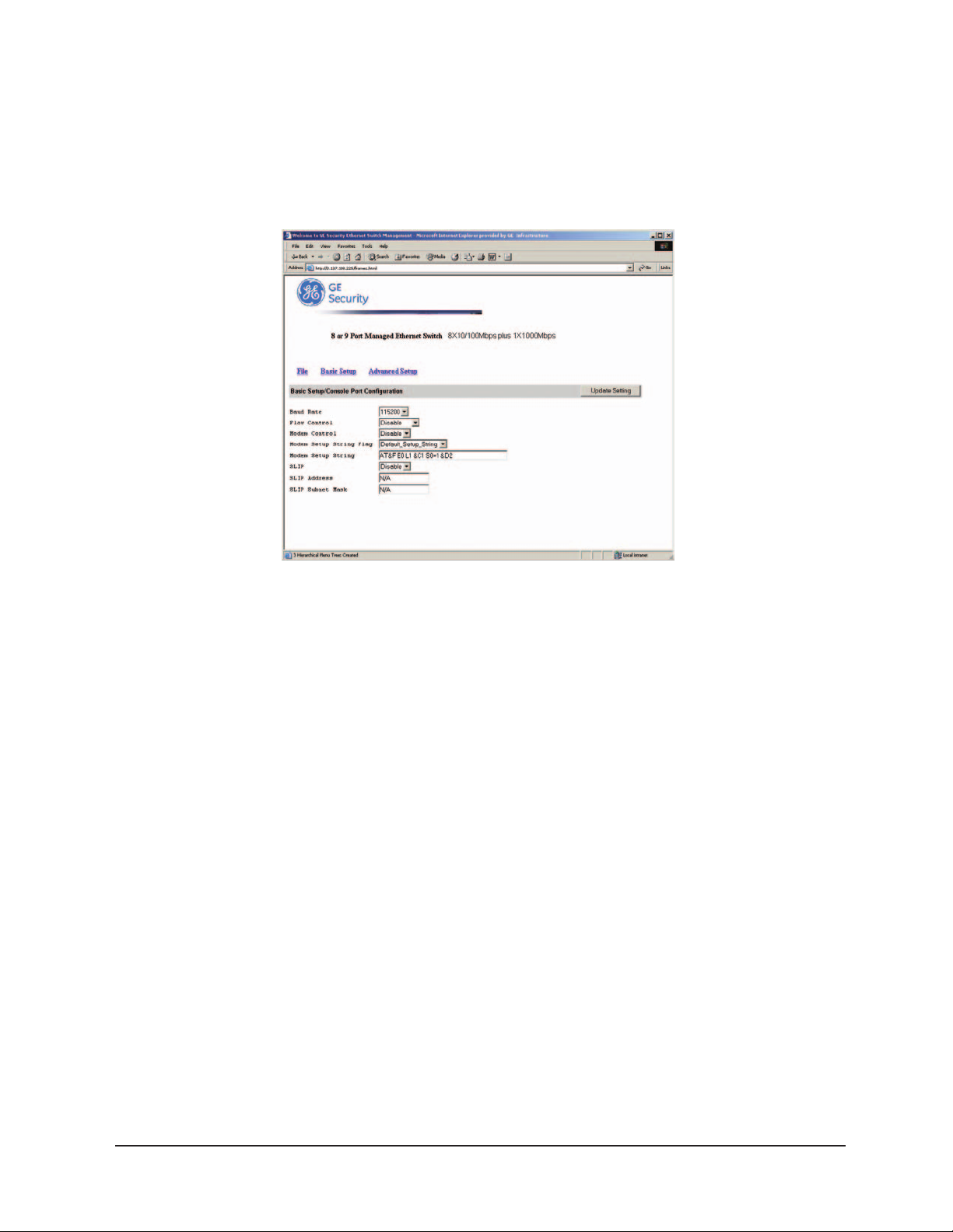
Console Port Configuration
Step 1:
To access the console port configuration parameters, click Basic Setup button first
and then click
Console Port.
Step 2: Baud Rate
Click an appropriate speed from Baud Rate drop-down menu on the field of
Basic Setup/Console Port Configuration.
Note:
Auto:
allows the switch to Auto-baud between 9600bps and 115,200bps
All the other selections force a specific console baud rate.
Step 3: Flow Control
Click a flow control method from Flow Control drop-down menu.
Step 4: Modem Control
Step 5: Modem Setup String Flag
Step 6: Modem Setup String
Step 7:
Click Update Setting when completed. A confirmation window appears.
User’s Manual 73
Page 78
Manageable 8/9-Port Switch
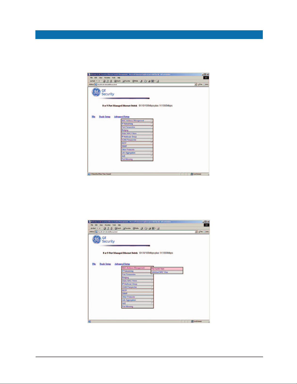
PERFORMING ADVANCED SETUP ACTIVITIES
To Perform Advanced Setup Activities:
Click the [Advanced Setup] button at the upper field of the main display,
the menu options appear.
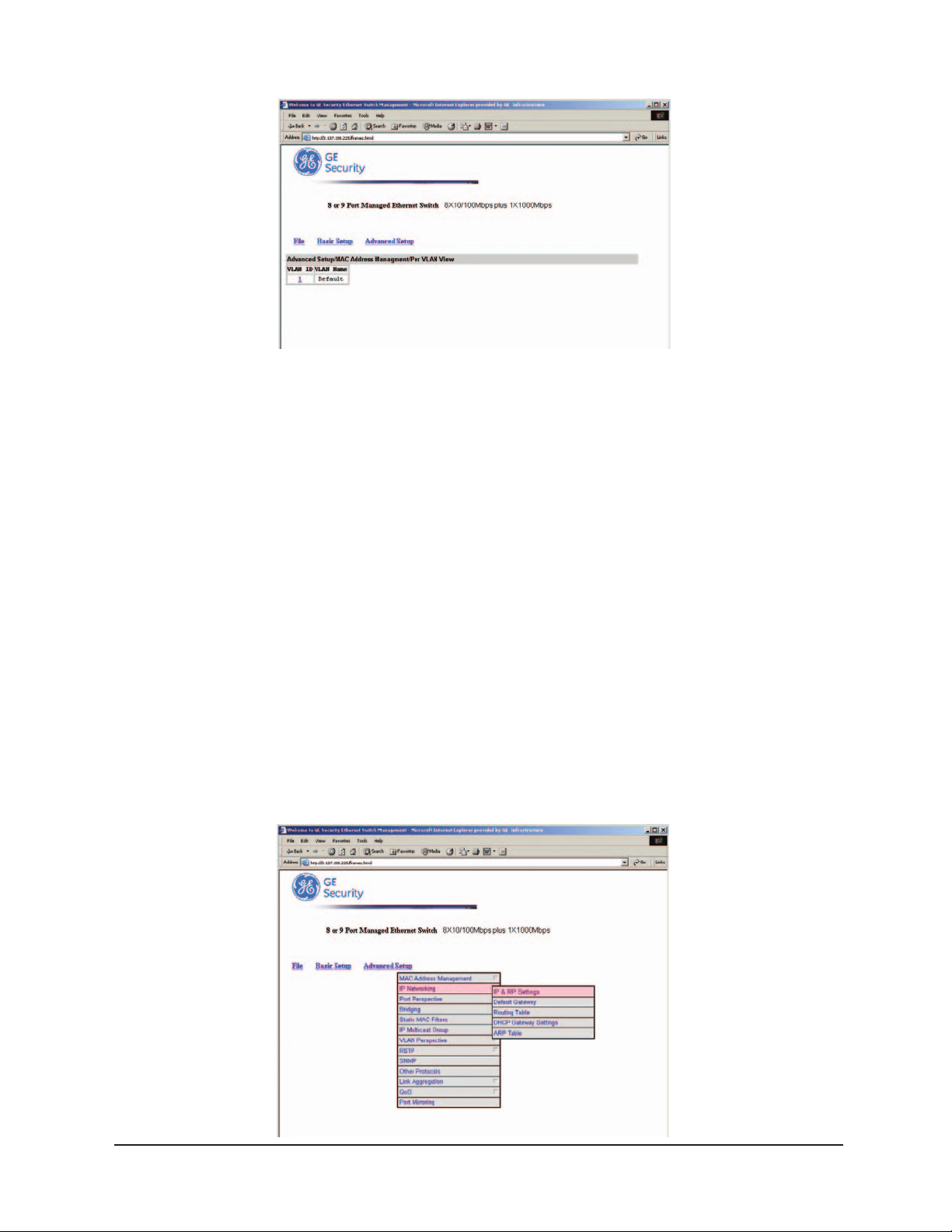
MAC Address Management
Step 1:
From the Advanced Setup menu, point to MAC Address Management to view VLANs and their
associated MAC addresses.
Step 2: Per VLAN View
Click Per VLAN View first and click on the port that you want to view.
Close the
’s Manual
User
VLAN Activities window when finished viewing.
74
Page 79
Manageable 8/9-Port Switch
Step 3: Per Port View
Click Per Port View first and click on the port that you want to view.
Close the
Per Port VLAN Activities window when finished viewing.
Step 4: Individual MAC View
From the Advanced Setup menu as shown in Step 1, point to
MAC Address Management. Click Individual MAC View.
Step 5:
Click in the Enter MAC Address text box and type the MAC address that you want to view.
Then click on the
Get Information button.
Step 6:
Close the Individual MAC View window when finished viewing.
IP Networking
To access the IP networking parameters, click the Advanced Setup button,
and Point to
IP Networking from the selection menu.
User
’s Manual
75
Page 80

Manageable 8/9-Port Switch
* No precautionar y message appears before you delete t he I P
addr ess.
* Be sure you want to delete it before doing so.
* The IP address is not deleted unti l you cl ick Update Setting.
Step 1: IP & RIP Settings
Click IP & RIP Settings to access IP and RIP settings.
A list of VLAN Ids appears, along with their corresponding IP address and subnet mask.
Step 2:
In the VLAN ID column, click a VLAN ID whose settings you want to view and/or change.
Step 3:
To change the IP Address, click in the text box and type a new address.
Alternatively, you can use the
Delete IP button to delete the IP address.
Caution:
Step 4:
To change the IP Subnet Mask, click in the text box and type a new address.
Step 5:
To change the Frame Type, click a value from the drop-down list.
Step 6:
To change the BOOTP selection, click a value from the drop-down list.
Step 7:
To change the Proxy ARP selection, click a value from the drop-down list.
Step 8:
To change the RIP Setting, click a value from the drop-down list.
Step 9:
Specify whether you want to broadcast, multicast, or neither from the dr
Step 10:
Specify whether you want to advertise routes.
Step 11:
Specify whether you want to advertise the default route.
Step 12:
Specify whether you want to accept RIP V1/V2 updates.
op-down list.
Step 13:
Specify whether you want to accept default route updates.
Click to close the confirmation window.
User’s Manual 76
Page 81

Manageable 8/9-Port Switch
Step 14:
Specify whether split horizon is to be used.
Step 15:
Specify whether poisoned reverse is to be used.
Step 16:
Specify whether the switch is to send triggered responses.
Step 17:
When you finished with these selections, click Update Setting.
A confirmation window appears. Click to close the confirmation window.
Per Port Statistics
Step 1:
To access per port statistics, click the Advanced Setup button, and then click Per Port Statistics
from the selection menu.
Step 2:
Click a port to view statistic data.
Step 3:
Click Update Setting when completed.
Port Priority
Step 1:
To access port priority, click the Advanced Setup button, and then click Port Priority
from the selection menu.
Step 2:
Click a port to change the priority level.
Step 3:
Click the drop-down list for setting a proper priority level.
Step 4:
Click Update Setting when completed.
Bridging
Step 1:
To access bridging parameters, click the Advanced Setup button, and then click Bridging
from the selection menu.
’s Manual
User
77
Page 82
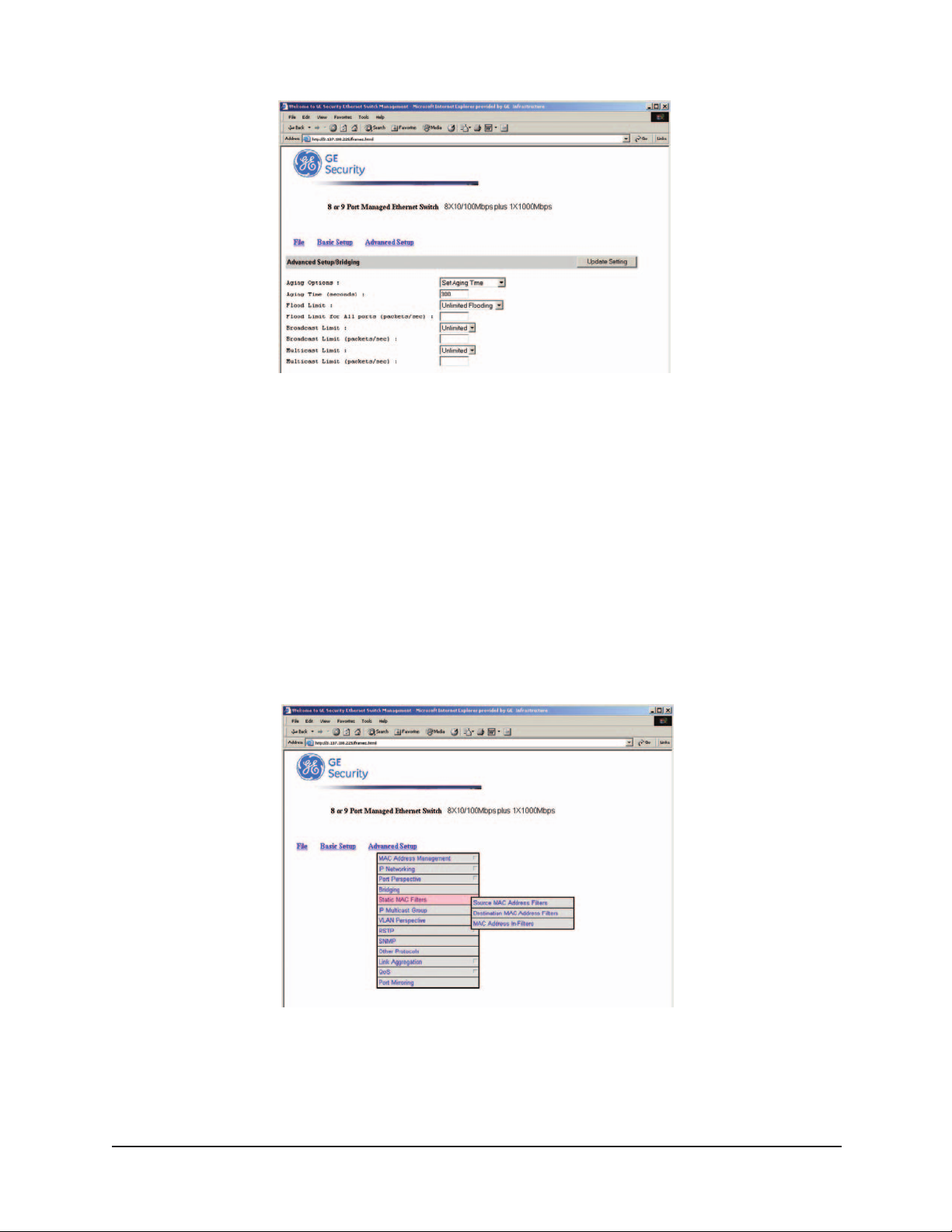
Manageable 8/9-Port Switch
Step 2: Aging Options
Click the drop-down list for Disabled (No Aging) or Set Aging Time.
Step 3: Aging Time
Click the text box and type a decimal number as bridge aging period in seconds.
Step 4: Flood Limit
Click the drop-down list for No Flooding, Controlled Flooding, Unlimited Flooding.
Step 5: Flood Limit for All Ports
Click the text box and type a decimal number as flood limit in packets per second.
Static MAC Filter
To access the static MAC filter parameters, click the Advanced Setup button, and point to Static
MAC Filter in the selection menu.
Step 1: Source MAC Address Filter
Click Source MAC Address Filters.
Step 2:
Click Add MAC Addr button to add a source MAC address for static filtering.
’s Manual 78
User
Page 83

Manageable 8/9-Port Switch
Step 3:
The Static Source MAC Filter window appears. Click in the Source MAC Address Filter text box
and type a unique MAC source address you want to add. Then click the
Add button.
Step 4:
A confirmation window appears. Close the confirmation window.
Step 5:
If you no longer need a source MAC address, click Delete MAC Addr
button to delete it in Step 2.
Step 6:
The Delete Source MAC Address window appears. Click the Select a MAC Address drop-down list
and select the source MAC address you want to delete. Then click the
Delete button.
Step 7:
A confirmation window appears. Close the confirmation window.
Step 1: Destination MAC Address
Click the Advanced Setup button, and point to Static MAC Filter in the selection menu.
Destination MAC Address.
Click
Step 2:
Click Add MAC Addr button to add a destination MAC address for static filtering.
Refer to
Step 2~4 in Source MAC Address section for similar procedure.
Step 3:
Click Delete MAC Addr button to delete a destination MAC address for static filtering.
Refer to Step 5~7 in Source MAC Address section for similar procedure.
IP Multicast Group
To view the IP multicast group addresses, click the Advanced Setup button, and click IP Multicast
Group in the selection menu. The information is read-only.
VLAN Perspective
To view the VLAN configuration information, click the Advanced Setup button, and point to VLAN
Perspective in the selection menu.
User
’s Manual
79
Page 84

Manageable 8/9-Port Switch
IP Multicast Group
To view the IP multicast group addresses, click the Advanced Setup button, and click IP Multicast
Group in the selection menu. The information is read-only.
VLAN Perspective
To view the VLAN configuration information, click the Advanced Setup button, and point to VLAN
Perspective in the selection menu.
Step 1: VLAN Configuration
Click VLAN Configuration.
Step 2:
Click on a VLAN ID whose VLAN configuration you want to change.
Step 3:
The VLAN Information window appears. Click to assign switch ports to VLAN ID 1. For each
switch, the port options include
Tagged Ports, Untagged Ports, or Forbidden Ports.
Step 4:
Click to close the VLAN Information window.
Step 5: Add a VLAN Entry
Click on the Add VLAN button to create a new VLAN.
User’s Manual 80
Page 85

Manageable 8/9-Port Switch
* No precautionar y message appears before you delete a
VLAN .
IP Multicast Group
To view the IP multicast group addresses, click the Advanced Setup button, and click IP Multicast
Group
in the selection menu. The information is read-only.
VLAN Perspective
To view the VLAN configuration information, click the Advanced Setup button, and point to VLAN
Perspective
in the selection menu.
Step 6:
The Add a VLAN Entry window appears.
Step 7:
Click in the VLAN ID text box and specify a new VLAN ID number.
Step 8:
Click in the VLAN Name text box and type a name for this newly created VLAN.
Step 9:
Click to assign switch ports to this VLAN. For each switch, the port options include
Tagged Ports, Untagged Ports, or Forbidden Ports.
Step 10:
Click Add Now button.
Step 11: Delete a VLAN Entry
Click on the Delete VLAN button to delete a VLAN. VLAN ID 1 is the default VLAN and
cannot be deleted.
Step 12:
The Delete a VLAN Entry window appears.
Step 13:
Click the drop-down menu to select a VLAN ID, which you want to delete.
Step 14:
Click the Delete button.
Caution:
User’s Manual 81
Page 86
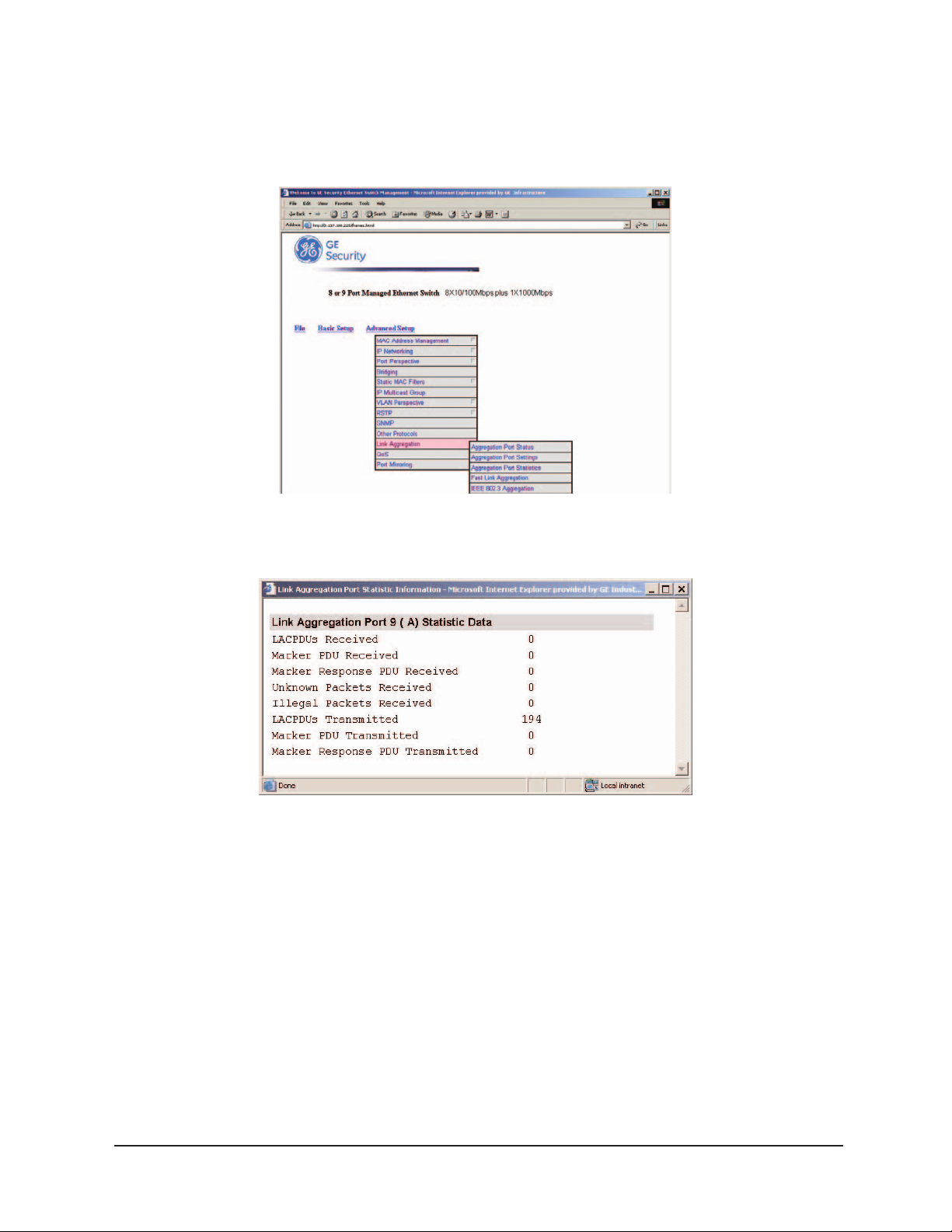
Manageable 8/9-Port Switch
Link Aggregation
To view the spanning tree perspective parameters, click the Advanced Setup button,
and point to
Link Aggregation in the selection menu.
Step 1: Aggregation Port Status
To view and/or change the Aggregation configurations, click Port Link Aggregation
from the above screen.
Step 2:
For Link Aggregation, specify whether you want to have it Disabled or Enabled by clicking
the drop-down list.
Step 3:
For Bridge Priority, click in the text box and type a decimal number between 0 and 65535.
Step 4:
For Hello Time, click in the text box and type a decimal number between 0 and 10.
Step 5:
For Max Age, click in the text box and type a decimal number between 6 and 40.
Step 6:
For Forward Delay, click in the text box and type a decimal number between 4 and 30.
User’s Manual 82
Page 87
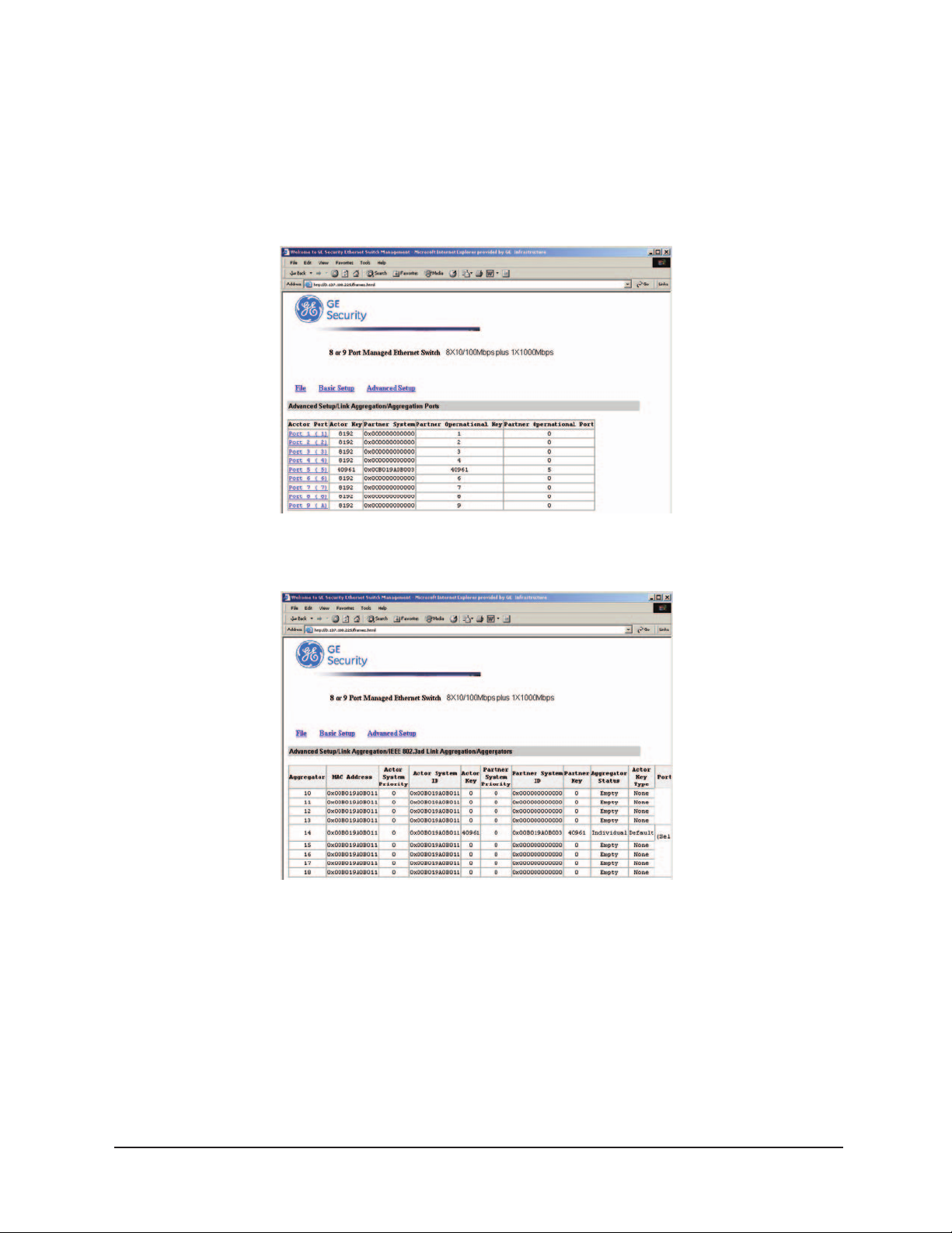
Manageable 8/9-Port Switch
Step 7:
Click Update Setting. A confirmation window appears. Close the confirmation window.
Step 1: Port Setting
To view and/or change the Spanning Tree configurations by port, click the
Advanced Setup button, point to Link Aggregation in the selection menu, and click Aggregation
Port Settings.
Step 2:
In the Port column, click the port whose Aggregation information you want to view.
Step 3:
For Port Priority, click in the text box and type a decimal number between 0 and 255.
A low value gives the port a greater likelihood of becoming a Root port.
Step 4:
For Path Cost, click in the text box and type a decimal number as a new path cost value.
Step 5:
For Port Status, specify whether the port is up or down by clicking the drop-down list.
Step 6:
Click Update Setting. A confirmation window appears. Close the confirmation window.
User’s Manual 83
Page 88
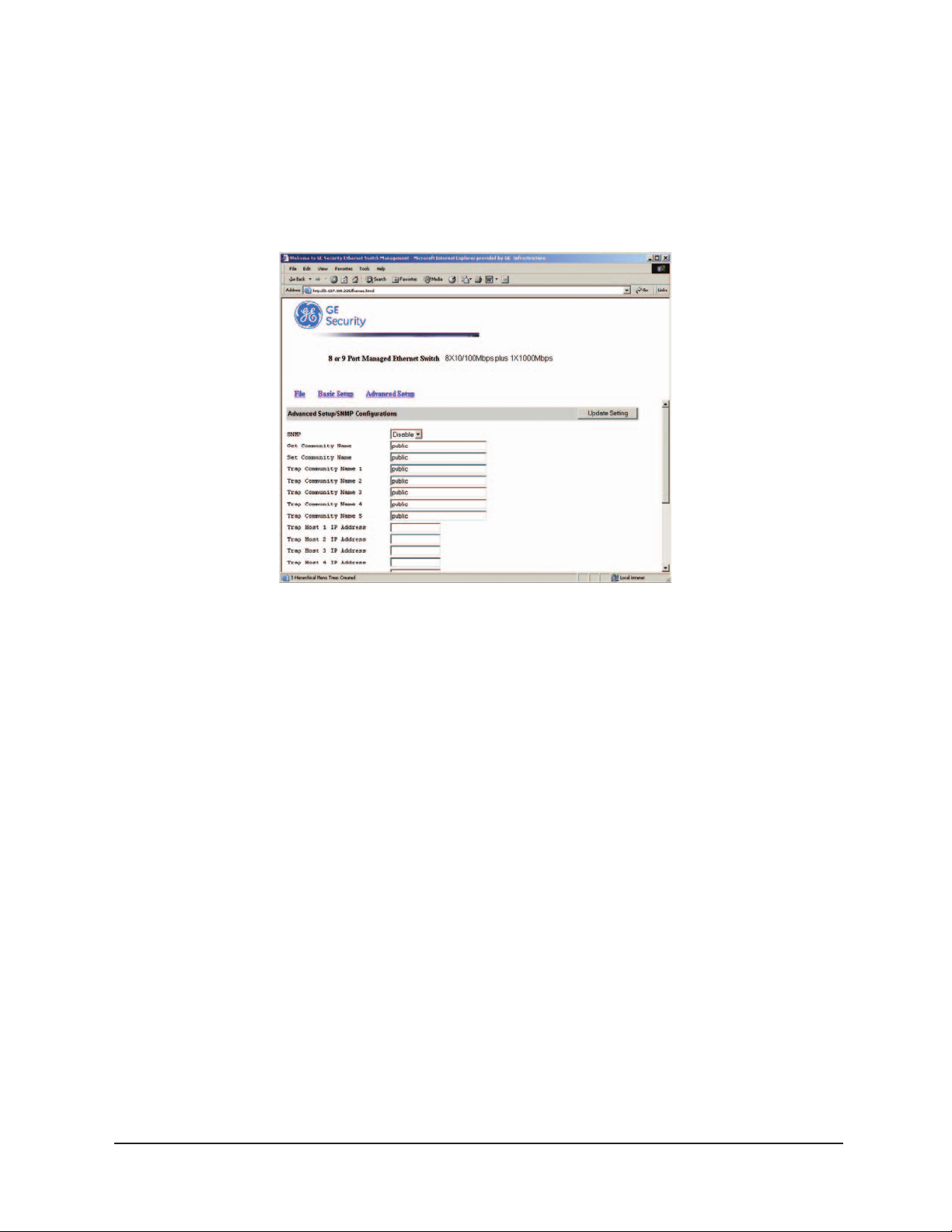
Manageable 8/9-Port Switch
SNMP
To view and/or change all SNMP-related information, click the Advanced Setup button, and
SNMP in the selection menu. The SNMP Configurations window appears.
click
As shown below, the factory-default
SNMP value is enabled and the factory-default
Community Name value is public.
Step 1: SNMP
For SNMP, specify whether it is Disabled or Enabled by clicking the drop-down list.
Step 2: Get Community Name
For Get Community Name, click in the text box and type a get community name.
Step 3: Set Community Name
For Set Community Name, click in the text box and type a set community name.
Step 4: Trap Community Name
For each Trap Community Name, click in the text bo
x and type a trap community name.
Step 5: Trap Host IP Address
For each Trap Host IP Address, click in the text box and type a IP address for trap host 1~4.
Step 6: Cold Start Trap
For Cold Start Trap, specify whether it is Disabled or Enabled by clicking the drop-down list.
Step 7: Warm Start Trap
For Warm Star
t Trap
, specify whether it is Disabled or Enabled by clicking the dr
op-down list.
Step 8: Link Down Trap
For Link Down Trap, specify whether it is Disabled or Enabled by clicking the drop-down list.
User’s Manual 84
Page 89

Manageable 8/9-Port Switch
Step 9: Link Up Trap
For Link Up Trap, specify whether it is Disabled or Enabled by clicking the drop-down list.
Step 10: Authentication Failure Trap
For Authentication Failure Trap, specify whether it is Disabled or Enabled by clicking the
drop-down list.
Step 11: Rising Alarm Trap
For Rising Alarm Trap, specify whether it is Disabled or Enabled by clicking the drop-down list.
Step 12: Falling Alarm Trap
For Falling Alarm Trap, specify whether it is Disabled or Enabled by clicking the drop-down list.
Step 13: Topology Alarm Trap
For Topology Alarm Trap, specify whether it is Disabled or Enabled by clicking the drop-down list.
Step 14: Update Setting
Click Update Setting when completed. A confirmation window appears.
Close the confirmation window.
Other Protocols
To enable or disable the GVRP and/or IGMP protocols, click the Advanced Setup button,
and click
Other Protocols in the selection menu.
Step 1: GVRP
For GVRP, specify whether it is Disabled or Enabled by clicking the drop-down list.
Step 2: IGMP
For IGMP, specify whether it is disabled or Passive or Active by clicking the drop-down list.
Step 3: Update Setting
Click Update Setting when completed. A confirmation window appears.
Close the confirmation window.
User’s Manual 85
Page 90
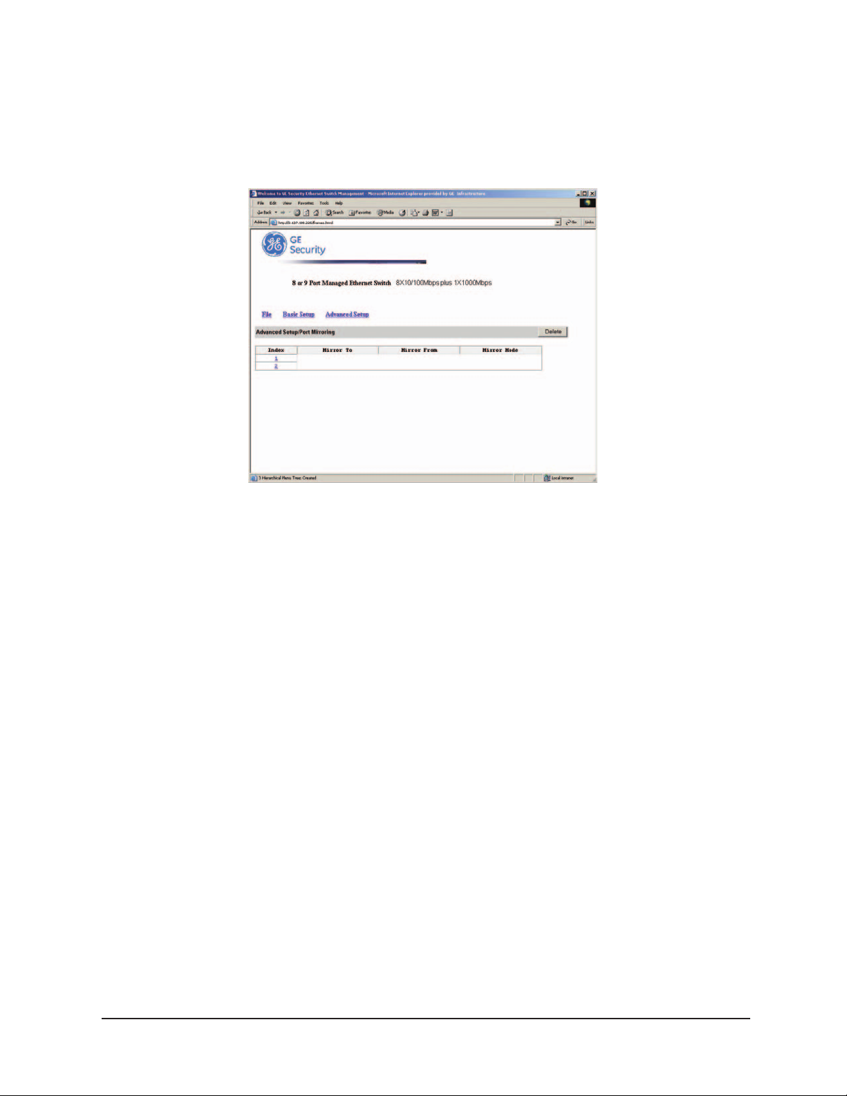
Manageable 8/9-Port Switch
Port Mirroring
To use the switch’s mirroring capability to mirror one port to Port 1, click the Advanced Setup
button, and click Port Mirroring in the selection menu. Click Port 1 in the Mirror To column.
Step 1: Mirror From
In the Mirror From column, select a "mirror from" port by clicking the drop-down list.
Data traffic from this port will mirror to
Port 1.
Step 2: Mirror Mode
In the Mirror Mode column, specify whether the "mirrored from" port will be receiving
or transmitting data by clicking the drop-down list.
Step 3: Update Setting
Click Update Setting when completed. A confirmation window appears.
Close the confirmation window.
User
’s Manual
86
Page 91

Manageable 8/9-Port Switch
SNMP & RMON MANAGEMENT
This section describes the switch’s Simple Network Management Protocol (SNMP) and
Remote Monitoring (RMON) capabilities.
OVERVIEW
RMON is an abbreviation for the Remote Monitoring MIB (Management Information Base).
RMON is a system defined by the Internet Engineering Task Force (IETF)
document RFC 1757, which defines how networks can be monitored remotely.
RMONs typically consist of two components: an RMON probe and a management
workstation:
- The RMON probe is an intelligent device or software agent that continually
collects statistics about a LAN segment or VLAN. The RMON probe transfers
the collected data to a management workstation on request or when a
pre-defined threshold is reached.
- The management workstation collects the statistics that the RMON probe
gathers. The workstation can reside on the same network as the probe, or it
can have an in-band or out-of-band connection to the probe.
The switch provides RMON capabilities that allow network administrators to set
parameters and view statistical counters defined in MIB-II, Bridge MIB, and RMON MIB.
RMON activities are performed at a Network Management Station running an SNMP
network management application with graphical user interface.
SNMP AGENT AND MIB-2 (RFC 1213)
The SNMP Agent running on the switch manager CPU is responsible for:
- Retrieving MIB counters from various layers of software modules according to the
SNMP GET/GET NEXT frame messages.
- Setting MIB variables according to the SNMP SET frame message.
- Generating an SNMP TRAP frame message to the Network Management Station if the
threshold of a certain MIB counter is reached or if other trap conditions (such as the
following) are met:
’s Manual 87
User
Page 92

Manageable 8/9-Port Switch
Warm start
Cold start
Link up
Link down
Authentication failure
Rising alarm
Falling alarm
Topology alarm
MIB-2 defines a set of manageable objects in various layers of the TCP/IP protocol suites. MIB-2
covers all manageable objects from layer 1 to layer 4 and, as a result, is the major SNMP MIB
supported by all vendors in the networking industry. The switch supports a complete
implementation of SNMP Agent and MIB-2.
RMON MIB (RFC 1757) AND BRIDGE MIB (RFC 1493)
The switch provides hardware-based RMON counters in the switch chipset. The switch manager
CPU polls these counters periodically to collect the statistics in a format that complies with the
RMON MIB definition.
RMON Groups Supported
The switch supports the following RMON MIB groups defined in RFC 1757:
- RMON Statistics Group – maintains utilization and error statistics for the
switch port being monitored.
- RMON History Group – gathers and stores periodic statistical samples
from the previous Statistics Group.
- RMON Alarm Group – allows a network administrator to define alarm thresholds for
any MIB variable. An alarm can be associated with Low Threshold, High Threshold,
or both. A trigger can trigger an alarm when the value of a specific MIB variable exceeds
a threshold, falls below a threshold, or exceeds or falls below a threshold.
RMON Event Group – allows a network administrator to define actions based on alarms. SNMP
Traps are generated when RMON Alarms are triggered. The action taken in the Network
Management Station depends on the specific network management application.
User
’s Manual
88
Page 93

Manageable 8/9-Port Switch
Bridge Groups Supported
The switch supports the following four groups of Bridge MIB (RFC 1493):
- The dot1dBase Group – a mandatory group that contains the objects applicable to
all types of bridges.
- The dot1dStp Group – contains objects that denote the bridge’s state with respect to the
Spanning Tree Protocol. If a node does not implement the Spanning Tree Protocol, this group
will not be implemented. This group is applicable to any transparent only, source route, or
SRT bridge that implements the Spanning Tree Protocol.
- The dot1dTp Group – contains objects that describe the entity’s transparent bridging status.
This group is applicable to transparent operation only and SRT bridges.
- The dot1dStatic Group – contains objects that describe the entity’s destination-address
filtering status. This group is applicable to any type of bridge which performs destinationaddress filtering.
User
’s Manual
89
Page 94

SPECIFICATIONS
Manageable 8/9-Port Switch
Manageable
8/9-Port Switch
Applicable Standards
Switching Method
Forwarding Rate
10BaseT:
100BaseTX:
1000BaseTX:
Performance
Cable
110BaseT:
100/1000BaseTX:
100/1000BaseFX:
10/100/1000BaseT/TX auto-negotiating ports
with RJ-45 connectors and 100/1000BaseFX
fiber ports combination
IEEE 802.3 10BaseT
IEEE 802.3u, ab 100/1000BaseTX/FX
Store-and-Forward
10 / 20Mbps half / full-duplex
100 / 200Mbps half / full-duplex
1000/2000Mbps half/ full-duplex
148,80pps for 10Mbps
148,800pps for 100Mbps
1,488,000pps for 1000Mbps
2-pair UTP/STP Cat. 5, 5E, 6
2-pair UTP/STP Cat. 5E Both up to 100m (328ft)
MMF (50 or 62.5_m), SMF (9 or10_m)
LED Indicators
Dimensions
Net Weight
Power Input
Power Consumption
Operating Temperature
Storage Temperature
Humidity
Emissions
Per unit – Power status
Per port – LNK (Link) /ACT (Activity)
FDX/COL
W 8.5 in _ D 7.5 in _ H 1.75 in
4.5 lbs. Approx.
External power adapter 12-24V DC; 1A
12W max.
-40°C to 74° C
-40°C to 85° C
0%-95% non-condensing
FCC part 15 Class A, NEMA TS2, UL,
CE Mark Class A
’s Manual 90
User
Page 95

APPENDIX A - CONNECTOR PINOUTS
Pin arrangement of RJ-45 connectors:
Manageable 8/9-Port Switch
8
1
The following table lists the pin out of 10/100/1000BaseT/TX ports.
Pin Regular Ports Uplink Port
1
2
3
4
5
Input Receive Data +
Input Receive Data -
Output Transmit Data +
NC
NC
Output Transmit Data +
Output Transmit Data -
Input Receive Data +
NC
NC
User
6
7
8
’s Manual
Output Transmit Data -
NC
NC
Input Receive Data -
NC
NC
91
Page 96

Limited Warranty
a. GE Security warrants that its products are free from defects in workmanship and materials, and
will conform to GE Security’s published specifications, subject to the terms of this limited warranty. With respect to any product furnished by GE Security, the foregoing shall apply only to failures
o meet said warranty that appear within the applicable warranty period set forth in the
t
Equipment Return and Warranty Policy Statement
uyer and does not extend to any other party. GE Security is not responsible for conditions or
B
on our website. The warranty extends only to
applications over which GE Security has no control. Defects or problems as a result of such
onditions or applications are not the responsibility of GE Security. Such conditions include nor-
c
mal wear and tear; catastrophe; fault or negligence of the user or a party other than GE Security;
improper installation, application, storage, maintenance, or use of products; other causes external
to products;or failure to conform to any applicable recommendations of GE Security. The warranty does not cover, and GE Security does not warrant, batteries of any type used in connection
with other products furnished. To the extent that any product includes software or firmware,
whether included in a product furnished hereunder or provided separately, GE Security warrants
that such software/firmware will, at the time of delivery by GE security, conform in all material
respects to GE Security’s documentation relating to such software/firmware.
b. If any product fails to meet the limited warranty, GE Security shall, at its option, correct any
such failure by repairing any defective or damaged parts of damaged product, or make available,
FOB shipping point, any necessary repaired or replacement parts. GE Security reserves the right
to replace any product under warranty with new or remanufactured product . GE Security will not
be responsible for labor costs of removal or reinstallation of products. The repaired or replaced
product is then warranted under the terms of the limited warranty for the balance of the term of
the warranty or for 90 days, whichever is longer. For any warranty claim, Buyer should contact
Customer Service and request authorization to return the product.
c. The preceding subsections of this limited warranty set forth the exclusive remedies for claims
based on any defect, failure, malfunction, or any other performance or nonperformance of any
product, whether the claim is in contract , indemnity, warranty, tort (including negligence), strict
liability or otherwise, and however instituted. Upon expiration of the applicable limited warranty
period, any liability of GE security in connection with such exclusive remedies shall terminate, and
Buyer shall have 30 days after the warranty period to give written notice of any defects, failures,
malfunctions, or other performance or nonperformance issue that appeared during the warranty
period. Except as set forth in the section entitled
Patents, the foregoing limited warranty is
exclusive and in lieu of all other warranties, whether written, oral, implied, or statutory. NO
IMPLIED WARRANTY OF MERCHANTABILITY OR FITNESS FOR PARTICULAR PURPOSE SHALL APPLY.
ecurity
S
Customer Support
For assistance in installing, operating, maintaining, and troubleshooting this product,
refer to this document and any other documentation provided. If you still have questions,
please contact technical support during normal business hours (Monday through Friday,
excluding holidays, between 6 a.m. and 5 p.m. Pacific Time).
GE Security
Call: 888 437-3287 (US
, including Alaska and Haw
aii; Puer
Outside the toll-free area: 503 885-5700
Fax: 561 998-6224
www.gesecurity.com
.
S
.
U
T (561) 998-6100
T 888-GE-SECURITY
888 (437-3287)
F 561 998-6224
GESecurity.
.
www
As a company of innovation, GE Security reserves the right to change product specifications without notice.
For the latest pr
D-GES7600 R
com
oduct specifications visit GE Security online at www
eleased 06-OCTOBER-06
E rs-bctinfo@gesecurity.com
.GESecurity.com or contact your GE Sales Representative.
to Rico; Canada)
Canada
T 519-376-2430
F 519-376-7258
Asia
T 852-2907-8108
F 852-2142-5063
Australia
T 61-3-9239-1200
F 61-3-9239-1299
ope
Eur
T 44-113-238-1668
F 44-113-253-8121
Copyright © 2006 General Electric Company. All rights reserved.
Latin America
T 305-593-4301
F 305-593-4300
 Loading...