

Page 1
GE
D25
994-0081
Version 3.00 Revision 21
Grid Solutions
TM
Substation Controller
User's Manual
GE Information
Page 2

D25
User's Manual
GE Grid Solutions
2
are trademarks and service marks
Important
COPYRIGHT NOTICE
© 2003-2017, General Electric Company. All rights reserved.
The information contained in this online publication is the exclusive property of General Electric Company, except as otherwise
indicated. You may view, copy and print documents and graphics incorporated in this online publication (the “Documents”) subject
to the following: (1) the Documents may be used solely for personal, informational, non-commercial purposes; (2) the Documents
may not be modified or altered in any way; and (3) General Electric Company withholds permission for making the Documents or
any portion thereof accessible via the internet. Except as expressly provided herein, you may not use, copy, print, display,
reproduce, publish, license, post, transmit or distribute the Documents in whole or in part without the prior written permission of
General Electric Company.
The information contained in this online publication is subject to change without notice. The software described in this online
publication is supplied under license and may be used or copied only in accordance with the terms of such license.
TRADEMARK NOTICES
GE and
* Trademarks of General Electric Company.
IEC is a registered trademark of Commission Electrotechnique Internationale. Microsoft and Windows are registered trademarks of
Microsoft Corporation. Panasonic is a registered trademark of Matsushita Electric Industrial Co., Ltd. Tadiran is a registered
trademark of Tadiran Israel Electronics Industries Ltd.
Other company or product names mentioned in this document may be trademarks or registered trademarks of their respective
companies.
of General Electric Company.
The circuit boards in the D25 contain many electrostatically sensitive
electronic components.
To prevent damage when handling these products use approved static
control procedures.
994-0081-3.00-21 GE Information
Page 3

GE Grid Solutions
D25
User's Manual
3
Contents
About This Document ................................................................................................................................. 6
Product Support 9
GE Grid Solutions Web Site ............................................................................................... 9
GE Grid Solutions Technical Support Library ................................................................... 9
GE Grid Solutions Technical Support ................................................................................ 9
Product Returns ................................................................................................................. 10
Chapter 1: Before You Start ............................................................................................................. 11
Product Safety ................................................................................................................... 11
Product Overview ............................................................................................................. 14
Restriction of Hazardous Substances (RoHS) .................................................................. 15
Chapter 2: Installing the D25 ............................................................................................................ 18
Installation Tools List ....................................................................................................... 18
Installation Steps ............................................................................................................... 18
First Look at the D25 ........................................................................................................ 19
Physical Mounting ............................................................................................................ 21
LCD Panel Overview ........................................................................................................ 22
Graphic Display Panel (GDP) and Color GDP (CGDP) Overview .................................. 24
Configuration of a GDP .................................................................................................... 27
Set Up of a Color GDP (CGDP) ....................................................................................... 28
Connecting Field Wiring .................................................................................................. 33
Power Supply .................................................................................................................... 33
Digital Inputs .................................................................................................................... 34
Control Outputs ................................................................................................................. 41
DC Analog Inputs ............................................................................................................. 65
AC Analog Inputs ............................................................................................................. 67
Communications Ports ...................................................................................................... 68
Configuring the D25 to work with a DNP3 I/O Module .................................................. 78
Chapter 3: Powering-up and Testing ............................................................................................... 80
Testing Utilities ................................................................................................................. 80
Boot Up ............................................................................................................................. 82
Using WESMAINT .......................................................................................................... 83
Testing Hardware I/O Points ............................................................................................ 85
Chapter 4: Configuring the D25 Software ....................................................................................... 93
D25 Software .................................................................................................................... 93
GE Information 994-0081-3.00-21
Page 4

D25
User's Manual
GE Grid Solutions
4
Downloading a Configuration........................................................................................... 96
Chapter 5: Operating the D25 ......................................................................................................... 105
LED Indicators ................................................................................................................ 105
Controls Switch ............................................................................................................... 106
Using Current-Monitored Digital Outputs ...................................................................... 108
Chapter 6: Servicing the D25 .......................................................................................................... 110
Fuse Replacement ........................................................................................................... 111
Battery Replacement ....................................................................................................... 113
Chapter 7: Upgrading and Replacing D25 Modules ..................................................................... 116
Module Replacement ...................................................................................................... 116
Main Board ..................................................................................................................... 118
DDSP Modules ............................................................................................................... 122
Memory Expansion Board .............................................................................................. 123
Shelf Plate ....................................................................................................................... 123
Configuring Radio Keying Option.................................................................................. 126
D25 Ethernet Card 100Base (10/100Base-T and 100Base-FX) ..................................... 127
Power Supply Card ......................................................................................................... 129
Digital Input Cards .......................................................................................................... 131
Digital Output Card ........................................................................................................ 132
DC Analog Input Card .................................................................................................... 133
CT/PT Modules ............................................................................................................... 134
Reconnecting Power ....................................................................................................... 143
Chapter 8: Troubleshooting ............................................................................................................ 144
Run-time and Startup Problems ...................................................................................... 144
Initialization Errors ......................................................................................................... 146
LAN-Based Problems ..................................................................................................... 147
Reporting Problems ........................................................................................................ 148
Appendix A: Product Specifications .................................................................................................. 152
Electrical Specifications.................................................................................................. 152
Testing and Certification................................................................................................. 156
Approvals ........................................................................................................................ 156
Physical Specifications ................................................................................................... 157
Storage and Battery ......................................................................................................... 158
Appendix B: Engineering Value Calculations .................................................................................. 159
Conversion Formulas ...................................................................................................... 159
994-0081-3.00-21 GE Information
Page 5

GE Grid Solutions
D25
User's Manual
5
Appendix C: Ordering Information ................................................................................................... 161
Appendix D: Installing and Connecting DNP3 I/O Modules .............................................................. 162
Overall Procedure to Install and Connect DNP3 I/O Modules ....................................... 162
Installing DNP3 I/O Modules in a Rack ......................................................................... 163
Connecting DNP3 I/O Modules (Low Voltage) ............................................................. 165
GE Information 994-0081-3.00-21
Page 6

D25
User's Manual
6
About This Document
Purpose
Intended
Audience
Additional
Documents
The purpose of this document is to provide users with information on how to
install and commission a D25* IED. This guide also provides details on the
operation and maintenance of D25 IEDs.
This document is intended for readers who are installing or maintaining a D25
IED. Readers are assumed to have background knowledge of substation
automation equipment and practices.
For further information about the D25 IED, refer to the following documents:
• D25 Plant I/O Subsystem Configuration Guide (P097-0CG)
• 68K Monitor User’s Guide (SWM0023)
GE Grid Solutions
• SGConfig* Online Help
• WESMAINT II+ User’s Guide (B014-1UG)
• All related Product Bulletins
994-0081-3.00-21 GE Information
Page 7

GE Grid Solutions
D25
User's Manual
7
FX
Document
Scope
The following part numbers are not covered by this document. For
information on these parts, please refer to the D25 Multifunction IED
Installation and Maintenance Guide (994-0023).
For upgrading information and understanding the compatibility between the
new parts and obsolete parts, refer to Product Bulletin PRBT-0233 D25 Parts
Compatibility and Upgrade Guide.
Main Boards
504-0005 D25 WESDAC Type II
504-0010 D25 WESDAC Type II, 2MB Flash
Power Supplies
521-0118 D25 HV Power Supply, 140 - 300 VDC / 240 VAC, 24V Wetting
521-0119 D25 Power Supply, 20 - 60 VDC, 48V Wetting
521-0124 D25 Power Supply, 70 - 150 VDC, 24V Wetting
521-0135 D25 Power Supply, 60-150 VDC / 120 VAC, 24V Wetting
521-0136 D25 HV Power Supply, 250 VDC / 220 VAC, 24V Wetting
521-0138 D25 HV Power Supply, 250 VDC / 220 VAC, 48V Wetting
521-0139 D25 Power Supply, 60-150 VDC / 120 VAC, 48V Wetting
DC Analog Card
517-0397 D25 DC Analog I/P 8 Channel ± 5V
517-0404 D25 DC Analog I/P 8 Channel ± 1mA
517-0405 D25 DC Analog I/P 8 Channel ± 5mA
517-0406 D25 DC Analog I/P 8 Channel ± 10mA
517-0407 D25 DC Analog I/P 8 Channel ± 20mA
517-0408 D25 DC Analog I/P 16 Channel ± 1mA
517-0409 D25 DC Analog I/P 16 Channel ± 5mA
Ethernet Card
580-0993 D25 10BASE-FL XCOM Card
580-0994
This card is obsolete and is replaced by 504-0305LF. A 100BASEswitch or converter is required when upgrading from 580-0993 to 5040305LF, since 10BASE-FL is incompatible with 100BASE-FX
580-0994: D25 10BASE-T XCOM CARD
Replaced by 504-0305LF.
GE Information 994-0081-3.00-21
Page 8

D25
User's Manual
GE Grid Solutions
8
Document Scope (continued)
Analog Input Cards
Status Cards
0009 is the Gen 3 Plant I/O DSP Card and
517-0410 D25 DC Analog I/P 16 Channel ± 10mA
517-0411 D25 DC Analog I/P 16 Channel ± 20mA
517-0413 D25 DC Analog I/P 16 Channel ± 5V
517-0416 D25 DC Analog I/P 8 Channel Scalable Adapter
517-0417 D25 DC Analog I/P 16 Channel Scalable Adapter
517-0402 D25 Status Card, 32 Channel, 24V, 5mA
517-0403 D25 Status Card, 32 Channel, 48V, 5mA
517-0425 D25 Status Card, 32 Channel, 12V, 10mA
517-0426 D25 Status Card, 32 Channel, 120V, 0.75mA
517-0427 D25 Status Card, 32 Channel, 12V, 5mA
517-0428 D25 Status Card, 32 Channel, 250V, 0.75mA
517-0431 D25 Status Card, 16 Channel, 48V, 5mA
517-0432 D25 Status Card, 16 Channel, 24V, 5mA
517-0433 D25 Status Card, 16 Channel, 12V, 5mA
517-0434 D25 Status Card, 16 Channel, 120V, 0.75mA
517-0435 D25 Status Card, 16 Channel, 250V, 0.75mA
AC Input
504-0008 D25 Analog Interface Card (Gen 1)
504-0009
D25 Analog Interface Card (Gen 2 and Gen 3).
This card is obsolete. 504does not work with the Gen 4 Plant I/O (P097-0 v4xx or 5xx). In
addition, the 504-0015LF does not work with the Gen 3 Plant I/O
(P097-0 v3xx).
994-0081-3.00-21 GE Information
Page 9

GE Grid Solutions
D25
User's Manual
9
Product Support
If you need help with any aspect of your GE Grid Solutions product, you can:
• Access the GE Grid Solutions Web site
• Search the GE Grid Solutions Technical Support library
• Contact GE Grid Solutions Technical Support
GE Grid Solutions Web Site
The GE Grid Solutions Web site provides fast access to technical information, such as
manuals, release notes and knowledge base topics.
Visit us on the Web at: http://www.gegridsolutions.com
GE Grid Solutions Technical Support Library
This site serves as a document repository for post-sales requests. To get access to the
Technical Support Web site, go to: http://sc.ge.com/*SASTechSupport
GE Grid Solutions Technical Support
GE Grid Solutions Technical Support is open 24 hours a day, seven days a week for you
to talk directly to a GE representative.
In the U.S. and Canada, call toll-free: 1 800 547 8629.
International customers call: +1 905 927 7070
Or send an e-mail to: multilin.tech@ge.com
GE Information 994-0081-3.00-21
Page 10

D25
User's Manual
10
Product Returns
A Return Merchandise Authorization (RMA) number must accompany all
equipment being returned for repair, servicing, or for any other reason. Before
you return a product, please contact GE Grid Solutions to obtain a Return
Merchandise Authorization number and complete instructions for return
shipments.
Have the following information ready to give to GE Grid Solutions Technical
Support:
• Ship to address (the address that the product is to be returned to)
• Bill to address (the address that the invoice is to be sent to)
• Contact name
• Contact phone number
• Contact fax number
• Contact e-mail address
GE Grid Solutions
• Product number / serial number
• Description of problem
Technical Support will provide you with a case number for your reference.
This case number is NOT the RMA number. You will be sent the RMA
number and RMA documents via fax or e-mail. Once you receive the RMA
documents, attach them to the outside of the box that your product is
packaged in and send the product to GE.
Note: Product returns will not be accepted unless accompanied by the Return
Merchandise Authorization number.
994-0081-3.00-21 GE Information
Page 11

GE Grid Solutions
D25
User's Manual
11
Chapter 1: Before You Start
Product Safety
Resolving
Problems
Safety
Precautions
If you attempt to resolve problems with your GE product using methods not
recommended by GE Grid Solutions, this might result in damage or injury to
persons and property.
Follow all safety precautions and instructions in this manual:
• Only qualified personnel should work on the D25. Maintenance personnel
should be familiar with hazards associated with electrical equipment.
• All AC voltage and current terminals are protected from accidental contact by
mechanical safety shields. The D25 is designed so that field wiring does not
have to be touched or disconnected when removing printed circuit boards
(PCBs).
• Always use the puller that is provided to remove Modules that hold potentially
hazardous voltages. This is located inside the D25 front cover on the edge of the
Indicator Switch Card.
• The CONTROLS switch on the front panel of the D25 has a mechanical
protector to prevent accidental operation of the switch. The switch can be locked
in the Local or Remote position.
• All components within the D25 are susceptible to damage from electrostatic
discharge. Observe standard ESD precautions.
GE Information 994-0081-3.00-21
Page 12
D25
User's Manual
12
MAY BE PROTECTED BY ONE OR MORE OF
Product Safety, Continued
GE Grid Solutions
Warning
Symbols on
Enclosure Back
Panel
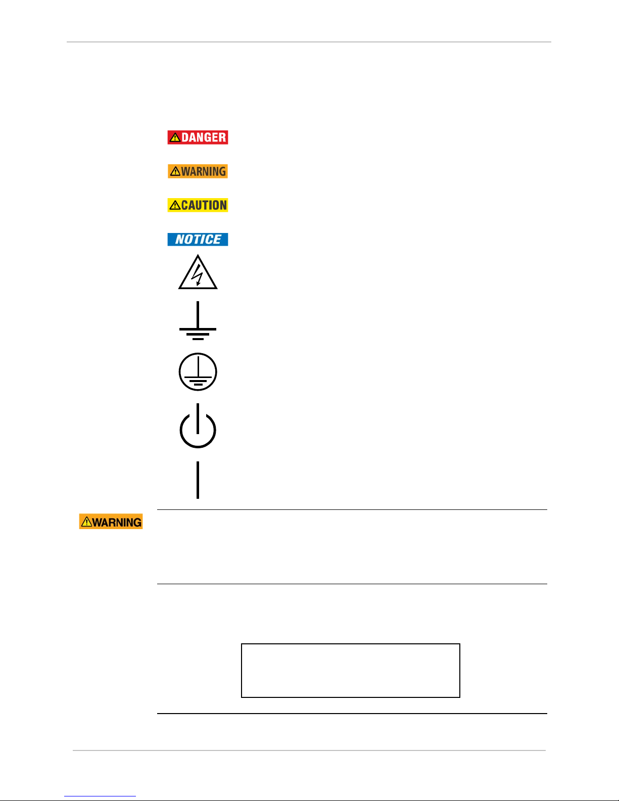
Indicates a hazardous situation which, if not avoided,
will result in death or serious injury.
Indicates a hazardous situation which, if not avoided,
could result in death or serious injury.
Indicates a hazardous situation which, if not avoided,
could result in minor or moderate injury.
Indicates practices that are not related to personal injury.
Caution Risk of electric shock
Earth Ground Terminal
Protective Ground Terminal
Power Supply Off (Stand-by Mode)
Hazardous
Voltages
Patent
Protection
Label
Power Supply On
Hazardous Voltages can cause shock, burns or death.
• Disconnect and lockout all power sources before servicing and removing
components.
• Short all current transformer primaries before servicing.
A label similar to the one shown below on the rear panel of the D25
enclosure. It is a formal notification of the US patents that protect the product
and the technology developed by GE Grid Solutions.
THE FOLLOWING US PATENTS:
5237511, 5303112, 5513061, 5701226
994-0081-3.00-21 GE Information
Page 13
GE Grid Solutions
D25
User's Manual
13
• The D25’s enclosure is intended for indoor use primarily to provide
!
Product Safety, Continued
Operating
Environment
Operation in
Residential
Areas
Protection
During
Maintenance
protection against accidental contact with the enclosed modules and
voltages.
− Do not place the product in environments where unusual conditions
exist (windblown dust and dirt, liquids, etc.) without a secondary
protective enclosure.
• Never operate the D25 in the field with front panel open.
− Operating the unit with the front panel open may alter product
performance specifications, and result in component damage from
debris.
The D25 generates radio frequency energy. If it is not operated and used in
accordance with the instructions provided in this guide, it may cause harmful
interference to radio communications in a residential area. Users are required
to correct interference at their own expense.
Ensure that the D25 is protected from falling debris during maintenance.
Small metallic particles (such as wire clippings) can fall through the
ventilation holes on the top of the unit, possibly damaging or interfering
with the safe and reliable operation of the D25.
If you cover the unit for maintenance, remove the cover before operating
to provide adequate cooling airflow.
Make sure that the metal case is grounded at the protective ground stud
Grounding
located at the top-left corner of the rear of the enclosure.
Connection must be provided with separate green/yellow wire connected
between the D25 and the protective earth system of the facility.
Use of this equipment in a manner not recommended or specified by GE Grid
Solutions may impair the protection provided by the equipment.
The high voltage area of the D25 High Current KE Digital Output Module is
in close proximity to the D25 chassis. Ensure that relay contacts are deenergized before removing the D25 HCKE DO Module.
GE Information 994-0081-3.00-21
Page 14
D25
User's Manual
14
Digital
Outputs
Analog
Processor
.....Future
Ethernet LAN
RS-232/485
Metering
Power Quality
LogicLinx
Digital Fault Recording
Substation Monitoring &
Diagnostics
Digital Inputs
AC/DC Analog
Inputs
IED 2
IED 1
UTC
WESMAINT
Auxiliary
Outputs
Communications
Options
Inpu/Output
Options
Direct CT
and PT
Trip/Close
Raise/Lower
COS
SOE
ACC
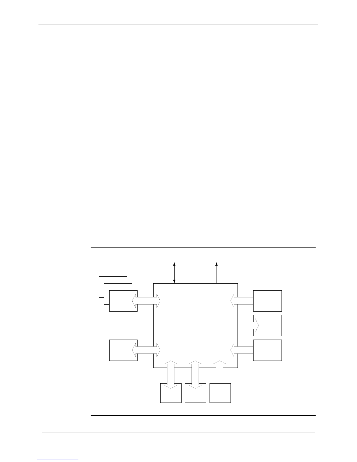
Product Overview
GE Grid Solutions
What is the
D25?
Main Features
and Options
Functional
Overview
The D25 is a standalone intelligent electronic device that can operate as:
• Programmable logic controller (PLC)
• Substation LAN node
• IED gateway
• Bay level controller
• Power quality monitor
• Fault/event (waveform) recorder
It is suitable for various power system applications, including:
• Substation monitoring
• Control
• Automation applications
The multi-processor design allows many functional options:
• Expansion cards
• Configurable digital inputs, digital outputs, AC and DC analog inputs
• LCD and Graphics Display front panels
Communication plug-in options:
• LAN: connection to iSCS Ethernet LAN with fiber optic, twisted pair or coaxial
• Serial: user selectable from RS-232 or RS-485
994-0081-3.00-21 GE Information
Page 15
GE Grid Solutions
D25
User's Manual
15
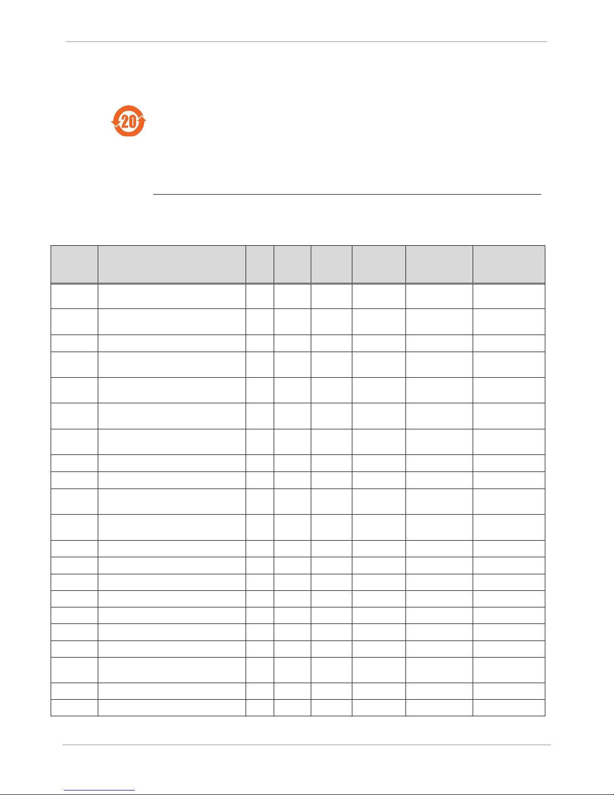
The environmental protection use period (EPUP), as defined in PRC
RoHS Material Declaration Data Content by PCB Assembly
GE Part
Description
Lead
Mercury
Cadmium
Hexavalent
Polybrominated
Polybrominated
450-0083
Transformer, 63.5V Nom 158.75V Max
X
450-0084
Transformer, 120V Nom, 300V Max Panel
X
O O O O O
450-0085
Transformer, 69.3V Nom, 173.25 Max
Panel
X
O O O O O
450-0088
Transformer, 5A Nom, 10A Max Panel
X
O O O O O
450-0090
Transformer, 220V Nom. 550V Max Panel
X
O O O O O
450-0105
XRFM, 1A Nom 2A Max, 400R, Panel
X
O O O O O
504-0009
D25 AIF/DSP-II Card
X
O O O O O
504-0013
D25 Main Bus Termination Card
X
O O O O O
504-0014LF
D25 MEMX 20M Card Lead Free
O O O O O
O
504-0015
D25 Dual DSP-50 2MB RAM Card
X O O O O
O
504-0306LF
D25 TYPE IV WESDAC Module, CE Mark
O O O O O
O
517-0401
D25 PT Module
X O O O O
O
Restriction of Hazardous Substances (RoHS)
SJ/T11363-2006, for the D25 hardware assemblies listed in the table below is
in excess of 20 years.
The following table shows the RoHS Material Declaration Data Content by
PCB Assembly
Table: RoHS
Compliance
Number
160-0081 512KX8 OTP EPROM 120NS PLCC IND
TEMP
Panel
450-0086 Transformer, 110V Nom, 146.67V FS.
Panel
450-0087 Transformer, 5A Nom, 10A Max Panel
Short
Long
450-0107 Transformer 1A Nom, 42A Max, 100R
Burden, CE Mark
450-0108 Transformer 5A NOM, 210A Max, 100R
Burden, CE Mark
(Pb)
(Hg)
O
O O O O O
O O O O O
X
O O O O O
X
O O O O O
X
O O O O O
X
O O O O O
(Cd)
Chromium
(Cr6)
biphenyls (PBB)
diphenyl ethers
(PBDE)
504-0207 D25 Type III WESDAC Module, CE Mark X O O O O O
504-0305LF D25 100FX and 10/100TX XCOM Card O O O O O O
580-0939 RAYMAR/Telenetic Standalone Digital Fast
Poll Modem
517-0400 D25 CT Module X O O O O O
X O O O O O
GE Information 994-0081-3.00-21
Page 16

D25
User's Manual
GE Grid Solutions
16
GE Part
Description
Lead
Mercury
Cadmium
Hexavalent
Polybrominated
Polybrominated
517-0401
D25 PT Module
X O O O O
O
517-0441
D25 CT Module - 400 Ohms Burden
X O O O O
O
517-0443
D25KE Control Module FACE 40
X O O O O
O
517-0449
D25 KE Control Module, DB25, 16 Channel
X O O O O
O
517-0452
D25 KE Control Module, FACE40, 16
X O O O O
O
517-0469
D25, 16ADC 5V Input Card SMT
X O O O O
O
517-0470
D25, 16ADC 1MA Input Card SMT
X O O O O O 517-0474
D25, 16 ADC 10MA Input Card SMT
X
517-0478
D25, 16 ADC Socketed Input Card SMT
X O O O O
O
517-0485
D25 32CH Status Input Module, 12V
X O O O O O 517-0486
D25 32CH Status Input Module, 24V
X O O O O O 517-0487
D25 32CH Status Input Module, 48V
X O O O O O 517-0488
D25 32CH Status Input Module, 120V
X O O O O O 517-0489
D25 32CH Status Input Module, 250V
X O O O O O 517-0490
D25 32CH Status Input Module, 10mA, 24V
X O O O O
O
517-0492
D25 HC KE 32 Control w 8 SEAL-IN
X O O O O
O
521-0131
D25 PSA Card
X O O O O
O
521-0143
D25 120VAC/60-150VDC Power Supply,
X O O O O O 521-0144
D25 120VAC/60-150VDC Power Supply,
X O O O O
O
521-0146
D25 220VAC/250VDC Power Supply, 48V
X O O O O
O
530-0003
Analog Adaptor, Input 20MA/1V
X O O O O O 530-0004
Analog Adaptor, Input Voltage
X O O O O
O
530-0025
1.2MA/1V Input Analog Adaptor
X O O O O
O
Number
(Pb)
(Hg)
(Cd)
Chromium
biphenyls (PBB)
(Cr6)
517-0429 D25 High Accuracy CT Module X O O O O O
517-0447 D25KE Control Module DB25 X O O O O O
Channel
517-0456 D25 X42 CT X O O O O O
517-0476 D25, 16 ADC 20MA Input Card SMT X O O O O O
Wetting, CE Mark
diphenyl ethers
(PBDE)
Wetting, CE Mark
Wetting, CE Mark
Wetting, CE Mark
Wetting, CE Mark
Wetting, CE Mark
521-0119 D25 20-60VDC/48 Wetting Power Supply X O O O O O
24V Wetting, CE Mark
48V Wetting, CE Mark
521-0145 D25 220VAC/250VDC Power Supply, 24V
Wetting, CE Mark
Wetting, CE Mark
X O O O O O
530-0005 Analog Adaptor, Input 1MA/1V X O O O O O
994-0081-3.00-21 GE Information
Page 17

GE Grid Solutions
D25
User's Manual
17
GE Part
Description
Lead
Mercury
Cadmium
Hexavalent
Polybrominated
Polybrominated
530-0030
1.5MA/1V Input Analog Adaptor
X O O O O
O
530-0073
5MA/1V Input Analog Adaptor
X O O O O
O
530-0090
Analog Adaptor, I/P 1MA/5V
X O O O O O 530-0091
1.1MA/5V Input Analog Adaptor
X O O O O
O
530-0095
Analog Adaptor, Input 1.5MA/5V
X O O O O O 530-0108
Analog Adaptor, 2MA/5V I/P .01%
X O O O O
O
530-0141
Analog Adaptor, Input 10V
X O O O O
O
540-0248
Graphics LCD Assembly
X O O O O
O
540-0412
D25 IND Switch Card
X O O O O O 580-0894
D25 IEDRTC Card
X O O O O
O
580-0993
D25 10BASE-FL XCOM Card
X O O O O
O
580-3429
Multii-language touch screen LCD 512KB
X O O O O
O
580-3570
Graphic Display, Color, 5.7 inch, 640 x 480
X O O O O
O
580-3500
GDP OP-7100 600 Series Firmware with
X O O O O
O
955-9017
D25 Enclosure Type II
O O O O O
O
Number
(Pb)
(Hg)
(Cd)
Chromium
biphenyls (PBB)
(Cr6)
530-0045 Analog Adaptor, Input 2MA/1V X O O O O O
530-0052 Analog Adaptor, Input 20MA/5V X O O O O O
530-0073 5MA/1V I/P Analog Adaptor X O O O O O
530-0094 Analog Adaptor, Input 1.25MA/5V X O O O O O
530-0131 Analog Adaptor 12.8MA/5V X O O O O O
540-0256 D25 Data Display Assembly X O O O O O
diphenyl ethers
(PBDE)
580-0991 D25 SERIAL XCOM Card STD X O O O O O
580-0994 D25 10BASE-T XCOM Card X O O O O O
DNP Protocol (version 6.03)
O Indicates that this toxic or hazardous substance contained in all of the homogeneous materials for this item
is below the limit required in PRC SJ/T11363-2006 and EU Directive 2002/95/EC (RoHS)
X: Indicates that this toxic or hazardous substance contained in at least one of the homogeneous materials
used for this item is above the limit requirement in PRC SJ/T11363-2006 and EU Directive 2002/95/EC (RoHS)
The maximum concentration limits (MCV's) apply.
Lead (Pb) 0.1% by weight = 1000 mg/kg = 1000 ppm
Mercury (Hg) 0.1% by weight = 1000 mg/kg = 1000 ppm
Cadmium (Cd) 0.01% by weight = 100 mg/kg = 100 ppm
Chromium VI (Cr6) 0.1% by weight = 1000 mg/kg = 1000 ppm
PBB, PBDE 0.1% by weight = 1000 mg/kg = 1000 ppm
GE Information 994-0081-3.00-21
Page 18

D25
User's Manual
18
Multi-meter (for testing points)
Procedure
Follow these steps to install the D25:
Step
Action
1
Unpack the D25.
2
Using the First Look at the D25 section of this guide, inspect the D25
Product Safety for contact details.
3
Loosen the D25 front panel and remove the battery “PULL” tabs (one
place to insulate the battery during shipment.
4
Install the D25. Follow the procedure set out in section: Connecting
5
Carry out all field wiring connections and jumper settings
Input and output pinouts
6
Power-up the D25 and check for normal operation. See section:
the self-diagnostics and ascertain what is malfunctioning.
Chapter 2: Installing the D25
Installation Tools List
GE Grid Solutions
Installation
Tools List
Before you begin the install of the D25, gather the following:
• A Flat Screwdriver with 0.6x3.5 mm blade (for terminal block wiring)
• A #2 Phillips Screwdriver (for rack mounting the unit)
• Wire Cutters
• Wire Strippers
• Wire Crimping Tool
• Tie-wraps (for gathering extra wire)
•
Installation Steps
for damage.
Note: Report any damage immediately to GE Grid Solutions. See:
for the Mainboard battery, and one for the optional Memory
Expansion card battery). The D25 is delivered with these tabs in
Field Wiring.
configuration as set out in section: Configuring the D25 to work with
a DNP3 I/O Module:
• Power
• Serial and Ethernet communication
•
Configuring the D25 to work with a DNP3 I/O Module. Some testing
requires that code and configuration files have been downloaded to
the D25.
If the front panel Power and Run LEDs do not show normal
operation, then use WESMAINT to inspect the error messages from
994-0081-3.00-21 GE Information
Page 19
GE Grid Solutions
D25
User's Manual
19
WESMAINT
STATUS
CONTROLS
SWITCH
KEYPAD
LCD or Touch
Screen Graphical
Installation Steps, Continued
7 If the FLASH memory has been deleted or corrupted, then you
need to download the code and configuration files. See Chapter 4:
Configuring the D25 Software.
8 If you have to download code and configuration files, then go back
to step 5 and verify that the D25 is now operating correctly.
Note
If you are replacing a component that is already installed on the D25 or
upgrading a specific component, then see Chapter 7: Upgrading and
Replacing D25 Modules.
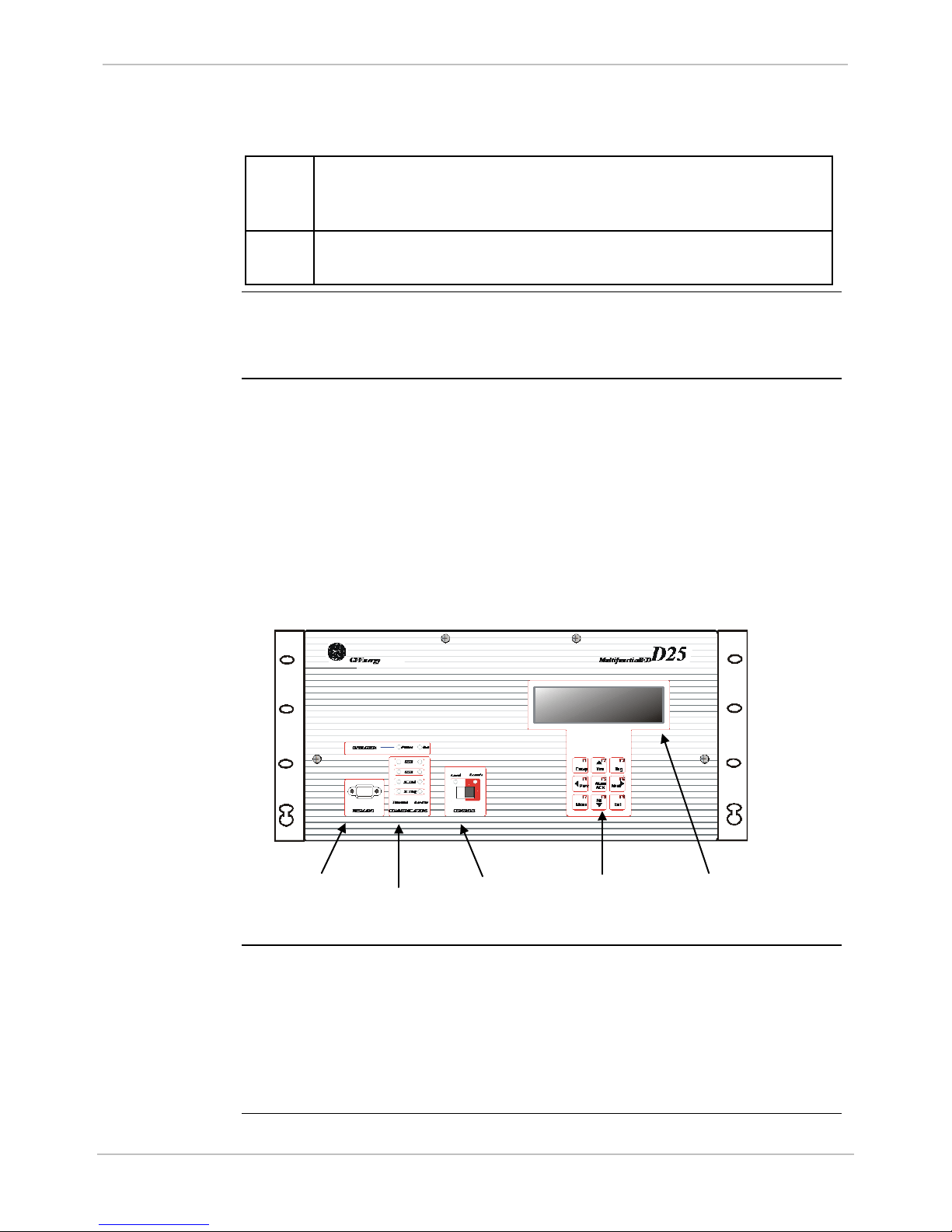
First Look at the D25
Front Panel
Back Panel
• WESMAINT II+ connector for connecting a maintenance terminal or PC
• LEDs for information on status, operation and traffic on communication ports
• CONTROLS switch for setting Local or Remote operational state of the digital
output module
• Optional LCD Display to display selected data stored in the D25 database
• Keypad for using the menus shown on the LCD Display. Only present if LCD
option is included
CONNECTOR
INDICATOR
DISPLAY
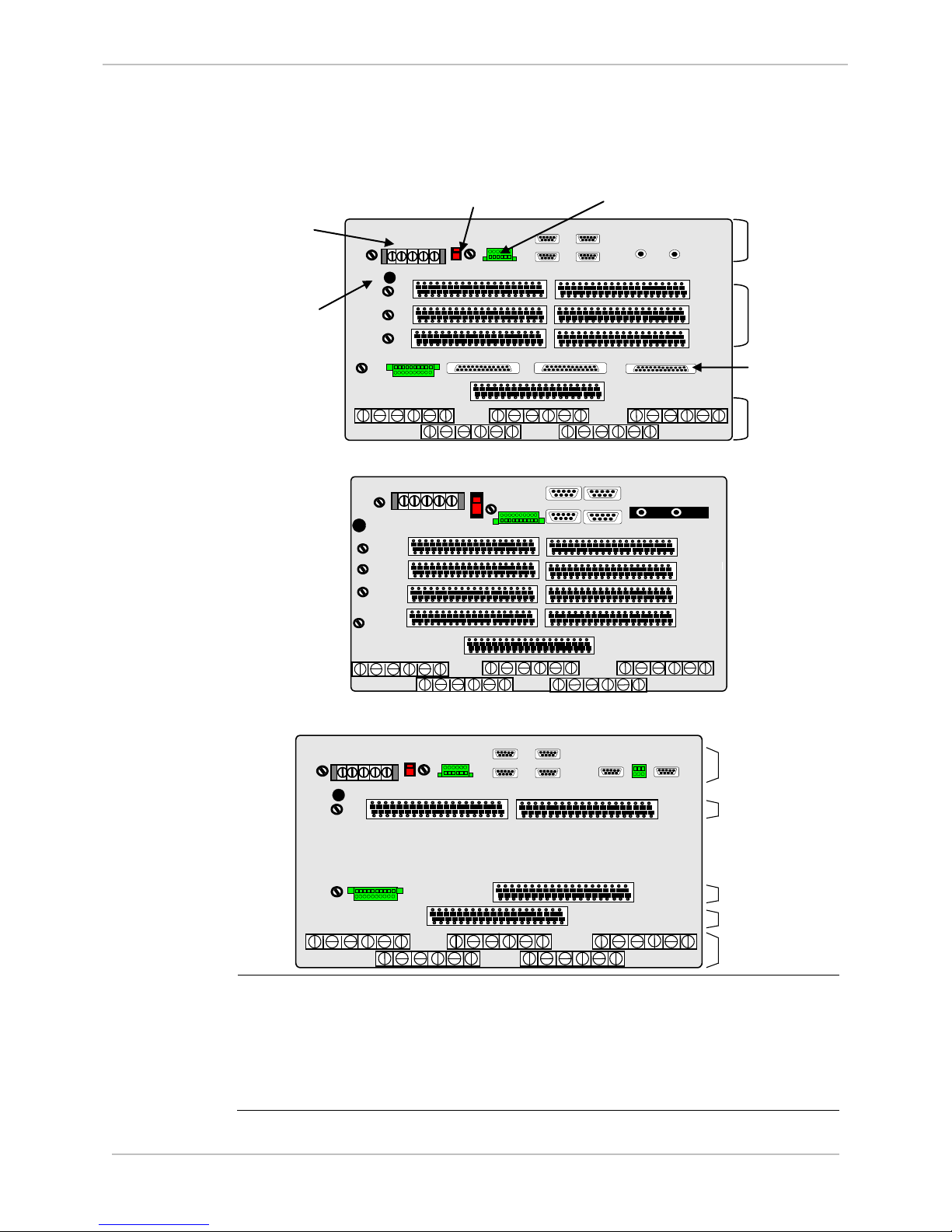
The D25 back panel is modular with removable sections. The types and
number of connectors are specified when the unit is ordered but can be
changed in the field.
There are two back panel options for the D25KE control board:
• Termination with six DB-25 connectors
• Termination with two FACE40 connectors
GE Information 994-0081-3.00-21
Page 20
D25
User's Manual
20
With six DB-25 connectors:
ON
OFF
POWER
A
D25 MAINT
IED 1
IED 2
UTC
C
E
B
D
F
DC
INPUTS
GND
XCOM 1
XCOM 2
J1 J2 J3
P1 P3 P5 P7 P9
P2 P4 P6 P8
1 3 5 7 9 11 13 15 17 19 21 23 25 27 29 31 33 35 37 39
2 4 6 8 10 12 14 16 18 20 22 24 26 28 30 32 34 36 38 40
2 1 2 1 2 1
FAIL AUX KEY
SYS RADIO
1 3 5 7 9 11 13 15 17 19 21 23 25 27 29 31 33 35 37 39
2 4 6 8 10 12 14 16 18 20 22 24 26 28 30 32 34 36 38 40
1 3 5 7 9 11 13 15 17 19 21 23 25 27 29 31 33 35 37 39
2 4 6 8 10 12 14 16 18 20 22 24 26 28 30 32 34 36 38 40
STATUS 1
FUSE - F3
STATUS 2 –
FUSE - F4
STATUS 3: -
FUSE - F5
FIELD
OUTPUT
FUSE – F1
PS FUSE
F2
AUXILIARY CONTROLS
B
D
F
H
DC ANALOG
INPUTS
P1 P3 P5 P7 P9
P2 P4 P6 P8
2 4 6 8 10 12 14 16 18 20 22 24 26 28 30 32 34 36 38 40
1 3 5 7 9 11 13 15 17 19 21 23 25 27 29 31 33 35 37 39
2 4 6 8 10 12 14 16 18 20 22 24 26 28 30 32 34 36 38 40
1 3 5 7 9 11 13 15 17 19 21 23 25 27 29 31 33 35 37 39
2 4 6 8 10 12 14 16 18 20 22 24 26 28 30 32 34 36 38 40
G
CONTROL
OUTPUTS
2 4 6 8 10 12 14 16 18 20 22 24 26 28 30 32 34 36 38 40
AC ANALOG
INPUTS
DC ANALOG
INPUTS
CONTROL
OUTPUTS
DIGITAL
INPUTS
COMMUNICATION
PORTS
XCOM 1 XCOM 2TB 31
CTRL PWR
FUSE – F6
ON
OFF
POWER
D25 MAINT
IED 1
IED 2
UTC
2 1 2 1 2 1
FAIL AUX KEY
SYS RADIO
FIELD
OUTPUT
FUSE – F1
PS FUSE
F2
A
GND
STATUS 1
FUSE - F3
POWER
A
D25 MAINT
IED / HOST 1
IED / HOST 2
UTC
C
B
D
DC ANALOG
INPUTS
GND
XCOM 1
XCOM 2
SYS
FAIL AUX KEY
6 5 4 3 2 1
RADIO
1 3 5 7 9 11 13 15 17 19 21 23 25 27 29 31 33 35 37 39
2 4 6 8 10 12 14 16 18 20 22 24 26 28 30 32 34 36 38 40
1 3 5 7 9 11 13 15 17 19 21 23 25 27 29 31 33 35 37 39
2 4 6 8 10 12 14 16 18 20 22 24 26 28 30 32 34 36 38 40
1 3 5 7 9 11 13 15 17 19 21 23 25 27 29 31 33 35 37 39
2 4 6 8 10 12 14 16 18 20 22 24 26 28 30 32 34 36 38 40
H
E F
G2
G1
GROUND STUD
POWER
CONNECTIONS
POWER SWITCH
DIGITAL INPUTS
COMMUNICATION
AC ANALOG
CONTROL
AUXILIARY CONTROLS
First Look at the D25, Continued
Back Panel
Diagrams
GE Grid Solutions
PORTS
OUTPUTS
With two FACE-40 connectors:
Legacy System Back Panel:
INPUTS
Part Number
The part number label on the rear of the enclosure identifies the D25 options
at the time of delivery (See Appendix C: Ordering Information):
• Each digit in the part number indicates the options included in the D25
• If the D25 is modified after delivery, the part number may no longer represent
• Update the part number label to match any option changes made after delivery
the options accurately
994-0081-3.00-21 GE Information
Page 21

GE Grid Solutions
D25
User's Manual
21
!
Physical Mounting
19” Rack
Physical
Mounting
Rack Spacing
Required
Clearances
Wiring Rod
Installation
To mount the D25 in a rack:
1. Align the D25 in the desired position in a 19-inch mounting rack.
2. Holding the D25 firmly in place in the rails of the mounting rack, install and
tighten the four rack screws.
You are now ready to connect all power and field wiring to the back of the D25, see
0 Connecting Field Wiring.
When mounting multiple D25s in a rack (or if mounting a D25 in a rack with other
equipment) verify that there is at least one rack unit (RU) space above and below the
D25 to allow for cooling airflow.
1 RU = 1.75 inches (44.5mm)
The exterior dimensions of the standard D25 enclosure are:
• 19” length x 9” deep x 8.75” high (483mm x 227mm x 222mm)
Clearance:
• Allow approximately 14 inches (356 mm) of total cabinet depth to provide
clearance for hardware on the front panel, and interface cables on the rear.
The optional D25 Wiring Rod assembly supports field wiring and prevents undue
stress on the connectors on the rear of the D25.
You require:
• Wire Rod Assembly, Part Number: 953-4029
• 2 - 6-32 - ½ inch LG Screws (screws removed from enclosure may be re-used, if
they are ½ inch long)
Mount the Wiring Rod on the back of the unit at a height where it will support cables
attached to the DB-25 or FACE-40 connectors.
GE Information 994-0081-3.00-21
Page 22
D25
User's Manual
22
M ultifunct ion IED
D25
COMM UN ICA TION S
WES MA IN T
Tra ns mit Receiv e
XCOM
2
XCOM
1
IED 2
IED 1
Power
Run
OPERATI ON
Local
Remot e
CONTROL S
F1 F2
Escape YesF3To g
F4 F5 F6
F7 F8 F9
Pre v
ACK
Alarm
Next
Menu
No
Ent
GE Energy Services
F
+
+ +
+
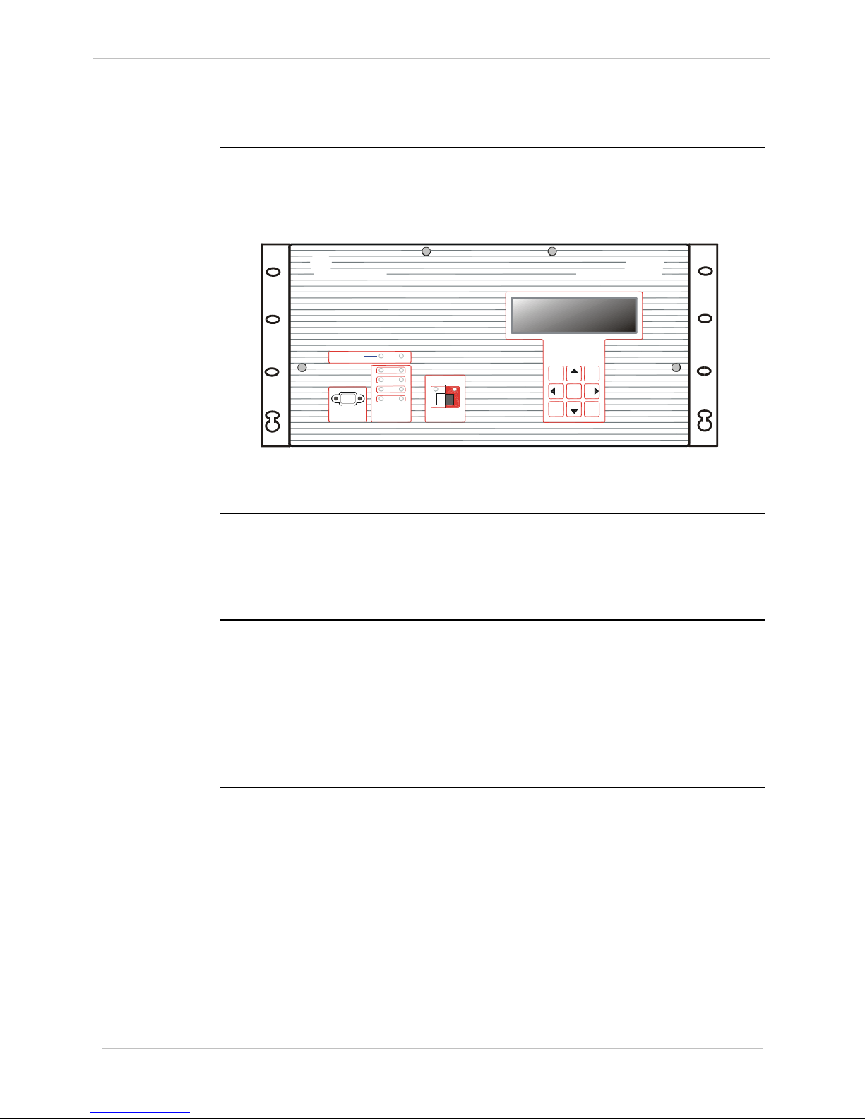
LCD Panel Overview
LCD Panel
Diagram
A Liquid Crystal Display Panel (LCD) option has been made available for
applications where alphanumeric front-panel display of analog and digital
system input points is desired.
GE Grid Solutions
Detailed
Description
Components of
an LCD Panel
System
This diagram shows a D25 front panel with the LCD option installed.
The touch-sensitive keypad below the LCD display can be used to navigate
through the display to show a set of select analog and digital input points.
The Data Display panel option is also available in a rack-mounted version
that can be linked, using the RS-485 multidrop technique.
A D25 must have these components to support an LCD system:
Hardware: Part #
− D25 Front Panel 953-3135
− LCD Text Display 540-0248
− LCD Circuit Board Assembly. 540-0256
− Ribbon Cable Assembly 976-0125
Continued on next page
994-0081-3.00-21 GE Information
Page 23

GE Grid Solutions
D25
User's Manual
23
LCD Panel Overview, Continued
Configuring
The Software
LCD Hardware
Connections
A D25 fitted with an LCD panel must be equipped with the Data Display
DTA (B062) application software to communicate with the panel.
Using SGConfig, specific D25 database input points are mapped into this
software.
A flat ribbon cable (Part # 976-0125) connects from the LCD card (Part #
540-0256) to the Indicator Switch card (Part # 540-0412) which is also
mounted on the inside of the front door of the D25 enclosure.
This cable is both the data and power connection to the LCD card.
GE Information 994-0081-3.00-21
Page 24
D25
User's Manual
GE Grid Solutions
24
M ultifunct ion IED
D25
COMM UN ICA TION SWES MA IN T
Tra ns mit Receive
XCOM 2
XCOM 1
IED 2
IED 1
Power
Run
OPERATI ON
Disabl e
Enable
CONTROL S
GE Energy Services
F
+
++
+
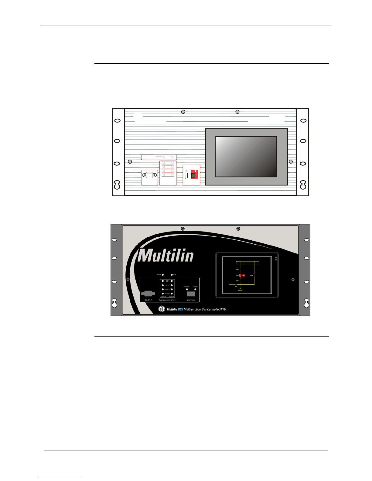
Graphic Display Panel (GDP) and Color GDP (CGDP) Overview
GDP/CGDP
Diagrams
A Graphic Display Panel (GDP) or a Color Graphic Display Panel (CGDP)
option has been made available for applications where graphic front-panel
display and control of system inputs and outputs is desired.
This diagram shows a D25 front panel with the GDP option installed.
This diagram shows a D25 front panel with the CGDP option installed.
Detailed
Description
The touch-sensitive GDP/CGDP can display a selection of customized
graphic displays, each representing a set of analog and digital input and
output points.
Using the touch-sensitive screen, an operator can select various displays,
select points to monitor and issue control commands
994-0081-3.00-21 GE Information
Page 25

GE Grid Solutions
D25
User's Manual
25
Graphic Display Panel (GDP) and Color GDP (CGDP) Overview,
Continued
Components of
a GDP/CGDP
A D25 must have these components to support a GDP system:
Hardware: Part #
− D25 Front Panel 953-3136
− GDP module 580-1186
− Ribbon Cable Assembly 976-0126
− Ribbon Cable Assembly 976-0127
− PSA module 521-0131
A D25 must have these components to support a CGDP system:
Hardware: Part #
− D25 Front Panel 504-0308LF
− CGDP module 580-3570
− Color GDP Cable Assembly 977-0548
GE Information 994-0081-3.00-21
Page 26

D25
User's Manual
GE Grid Solutions
26
!
Graphic Display Panel (GDP) and Color GDP (CGDP) Overview,
Continued
What Can a
GDP/CGDP be
Used For?
The GDP/CGDP can eliminate the need for discrete substation devices.
For example, the GDP/CGDP can be used in place of the following devices:
• circuit breaker control switch and semaphore
• disconnector / earth switch and semaphore
• ammeter, and ammeter selector switch
• voltmeter, and voltmeter selector switch
• MW meter
• power factor meter
• alarm annunciator panel
• mimic diagram.
There are jumper settings at the back of the GDP/CGDP unit that are set at
the factory. These settings shall not be changed and any modification to them
may cause damage to the GDP/CGDP or other modules of the D25.
IMPORTANT
A D25 equipped with a GDP/CGDP has these limitations:
• Only external status wetting can be used when the GDP/CGDP is installed.
− the D25’s power supply field O/P is used exclusively to power the
GDP/CGDP.
− connecting another external load to the field O/P will affect isolation, and
possibly overload the power supply.
• The GDP/CGDP reduces the normal -20° to +70°C operational temperature
rating of the D25 to 0° to +50°C.
• The 20-60 V
D25 power supply is not available with the GDP/CGDP.
DC
994-0081-3.00-21 GE Information
Page 27

GE Grid Solutions
D25
User's Manual
27
Configuration of a GDP
Configuring a
GDP’s
Software
GDP Hardware
Connections
A D25 fitted with a GDP must be equipped with the DNP 3.0 DPA
application software and will use the COM1 (D25 MAINT port) to
communicate with the GDP. Using SGConfig, some or all of the D25’s
database points are mapped into this communication software.
Inside the GDP, these points are then mapped into the GDP graphic objects.
For detailed information about configuring the DNP 3.0 DPA, refer to the
B021-0CG Configuration Guide.
For detailed information about setting up and configuring the GDP, refer to
the “IGPM 16200 Operation and Configuration Manual” (document number
16200-MOC-09-08-E).
To access the GDP manual:
1. Go to GE Grid Solutions Technical Support at:
http://www.gegridsolutions.com/TDSASSupport
2. Log in to the Technical Support Library.
3. Navigate to Substation Automation Products > D25 > GDP –
Monochrome > FW 603 Upgrade > Substation Bay Config Tool Ver
5.01.
4. Download and extract the file; the manual is located in the Manual
folder.
Please contact GE Grid Solutions to learn more about the configuration tools
and settings available for the GDP.
When installed, the PSA module (part # 521-0131) is mounted over the righthand side of the D25’s DAC board, where it plugs onto the three sets of
digital input wetting jumpers (see Low-Voltage Digital Input Card Wetting on
p. 120 for more detail on these jumpers). The PSA taps into the main D25
power supply’s field output through these jumpers.
A flat ribbon cable (Part # 976-0126) connects from the PSA card to the
Indicator Switch card (Part # 540-0412) mounted on the inside the front door
of the D25 enclosure. This cable is the data connection to the GDP.
Another cable (Part # 976-0127) links the PSA card to the GDP. This cable is
both the DC power connections from the PSA to the GDP, as well as the RS485 data interface.
GE Information 994-0081-3.00-21
Page 28
D25
User's Manual
28
PC
SGConfig
SBC Tool
300
D25 CGDP
RS-485
D25 Configuration
SB Viewer 300
(DNP DCA)
DNP PACKETs
SB Viewer 300 Configuration
DNP DPA
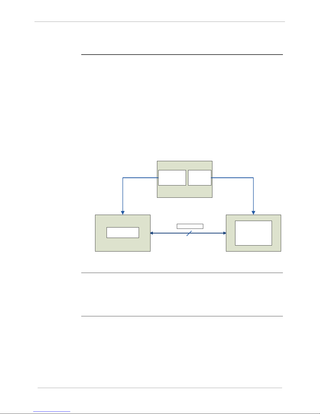
Set Up of a Color GDP (CGDP)
Overview
This section describes how to set up the Color Graphical Display Panel
(CGDP) on your D25*. The CGDP uses a licensed software package named
the GDP 300 from Quasar Controls, which you must register as part of the
setup procedure. The CGDP software includes system firmware named the
Substation Bay Viewer™ 300 (SB Viewer 300) that runs on the D25 CGDP
and a Windows-based editor named the Substation Bay Config Tool™ 300
(SBC Tool 300) that runs on a PC.
The diagram below shows the relationship between the PC, D25 and CGDP
(SB Viewer 3 00). The SB Viewer 300 and D25 communicate with each
other using the DNP protocol over RS-485. The SB Viewer 300 is configured
using the SBC Tool 300 running on the PC. The D25 is configured using
SGConfig which also run on the PC.
GE Grid Solutions
Prerequisites
Install the:
• Compact Flash Card (GE part number 160-0125) which includes
Windows Embedded CE and SB Viewer 300
• SBC Tool 300 in Windows 7 or Windows Server 2008
994-0081-3.00-21 GE Information
Page 29
GE Grid Solutions
D25
User's Manual
29
1. Go to the Quasar Controls website at:
Set Up of a Color GDP (CGDP), Continued
Set Up
Procedure
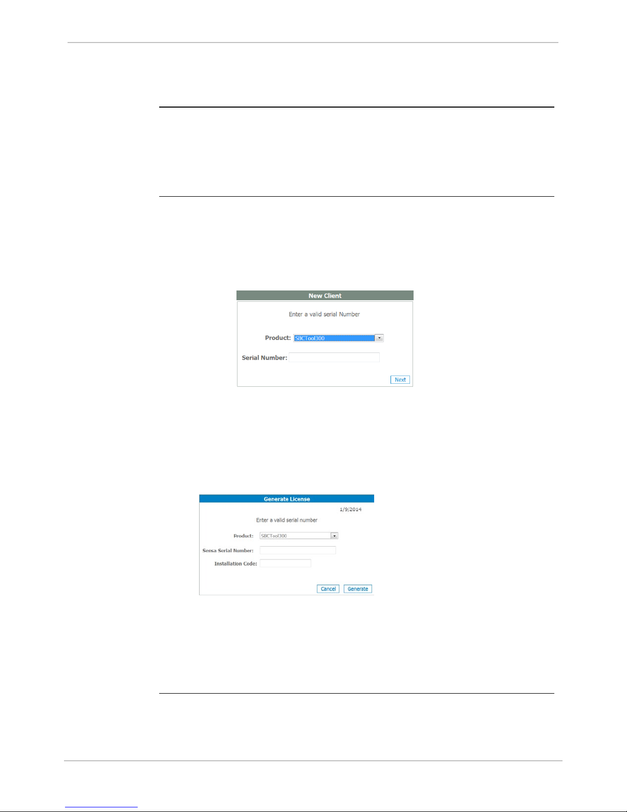
To Register the
SBC Tool 300
online:
Setting up the CGDP requires the following tasks:
1. Register the SBC Tool 300.
2. Create the configuration file using the SBC Tool 300.
3. Load the configuration file onto the CGDP.
http://200.23.18.184/LicenseReg/AllUsers/Login.aspx?ReturnUrl=%2fLicen
seReg%2fClientes%2fGenerarClave.aspx.
2. If you are a new client, you need to register.
a. Click Register.
Result: The New Client entry fields appear.
3. Sign in to the client account.
4. Click Generate Licenses.
Result: The Generate License window appears.
5. Input your valid Serial Number and Installation Code.
6. Click the Generate button.
Result: The license information appears. Also, Quasar Controls sends an
email to your client email address containing the license information.
Note: The SBC Tool 300 includes a 30-day trial license. You must register the
software with Quasar Controls within 30 days, or the license is de-activated.
b. Type in valid Serial Number for the SBC Tool 300.
c. Follow the web page instructions to complete the registration.
Result: After completing the registration or you have a new client
account.
GE Information 994-0081-3.00-21
Page 30

D25
User's Manual
30
When using the SBC Tool 300, refer to Section 4 of the “GDP 300 Operation
Set Up of a Color GDP (CGDP), Continued
To create the
configuration
file using the
SBC Tool 300:
and Configuration Manual” (document number 16300-MOC-13-4).
To access this manual:
1. Go to GE Grid Solutions Technical Support at:
http://www.gegridsolutions.com/TDSASSupport
2. Log in to the Technical Support Library.
3. Navigate to Substation Automation Products > D25 > GDP 300 –
Color > GDP 300 Operation and Configuration Manual.pdf.
A D25 fitted with the CGDP must be running DNP 3.0 DPA application
software and will use COM1 (D25 MAINT port) to communicate with the
CGDP (refer to the DNP V3.00 DPA Configuration Guide (B021-0CG)).
Using SGConfig, some or all of the D25’s database points are mapped into
this communication software. Inside the CGDP, these points are then mapped
into the CGDP graphic objects.
GE Grid Solutions
For DNP communications between the CGDP and the D25, both units must
use a matching serial port baud rate and DNP addresses.
Please contact GE Technical Support to learn more about the configuration
tools and settings available for CGDP.
994-0081-3.00-21 GE Information
Page 31

GE Grid Solutions
D25
User's Manual
31
1. On your PC, open your project in the SBC Tool 300.
Set Up of a Color GDP (CGDP), Continued
To load a
configuration
file onto the
CGDP from a
USB flash
drive:
2. From the SBC Tool 300 menu, click Transfer > Send configuration.
Result: The Send Configuration window appears.
3. Select the USB option.
4. Connect a USB flash drive to your computer.
5. Click the Refresh button in the Send configuration window.
Result: The connected drives are listed.
6. Select the location to which the configuration file is to be downloaded from
the USB drive. If you:
• Single-click the drive designation, the project is downloaded to the
root directory of the drive, creating a folder with the project name.
• Double-click, the system prompts you to select the exact path to
which the configuration file is to be downloaded from the USB flash
drive and creates a folder with the project name.
7. Click the Ok button.
Result: When the configuration file has been downloaded, an
acknowledgement window appears.
8. Click OK.
9. Power down the D25 and open the front panel.
10. Insert the USB flash drive into the CGDP.
11. Power on the D25 and copy the project folder from the USB flash drive to
the CGDP’s path.
12. Power down the D25, unplug the USB flash drive, and close the D25 front
panel.
13. Power on the D25 and select the configuration you just downloaded from the
CGDP screen.
Note: Alternatively, the configuration can be loaded through Ethernet. For details,
refer to the Section 4.5 in the “GDP 300 Operation and Configuration Manual”
(Digital document number 16300-MOC-13-4).
GE Information 994-0081-3.00-21
Page 32

D25
User's Manual
32
The CGDP software package makes the following software components available for
If you need help with any aspect of the GDP 300 firmware or configuration tool,
Set Up of a Color GDP (CGDP), Continued
Additional
Documentation
Software
License
Information
• GDP 300 Operation and Configuration Manual (document number
16300-MOC-13-4)
• DNP V3.00 DPA Configuration Guide (GE document number B021-
0CG).
use:
Software Component Description License Requirements
GE Grid Solutions
Quasar Controls
Product Support
Substation Bay Config
Tool 300 (SBC Tool
300)
Substation Bay Viewer
300 (SB Viewer 300)
contact:
Quasar Controls, S.A de C.V
Av. Morelos Oriente 2216,
Col. Centro Torreon,
Coahuila, Mexico C.P. 27000
Sales: +52 (871) 718-60-90
Customer Service: +52 (871) 718-60-90
Web Site: http://www.caname.org.mx/index.php/quasar-controls-s-a-de-c-v
PC-based tool to
create and download
a configuration file to
the CGDP.
Firmware program
that runs on the CGDP.
30-day trial license. Register within
30 days to obtain a licensed version.
See procedure, “To Register the SBC
Tool 300 online”.
License has already been applied.
994-0081-3.00-21 GE Information
Page 33

GE Grid Solutions
D25
User's Manual
33
-- Wetting
+ Wetting
+/L
-- /N
Aux.
Ground
• Positive if using DC power supply
• Negative if DC power supply
!
Connecting Field Wiring
This Section
Use this section to:
• Make all field wiring connections
• Set external jumper configurations
• Configure Serial and Ethernet ports
Power Supply
Power Supply
+ Wetting
Supply Output
- Wetting
Supply Output
+/L Input
-/N Input
Grounding
External
Overcurrent
Protection
A label on the back panel outlines the actual power connection points for the
Power Supply option installed.
Term # 1 2 3 4 5
Either +24V or +48V according to the power supply option specified.
Either -24V or -48V according to the power supply option specified.
• Line if AC power supply
• Neutral if AC power supply
Connect the protective ground stud before operating the D25. Tighten the
ground stud to a torque value between 4.2 to 5.0 in-lb [0.475 to 0.565 Nm]
Use the ground stud for shielding.
The D25 power supply input must be externally protected:
• AC mains supplies shall be fused at no more than 15A, or
• DC mains supplies shall be fused at no more than 10A
GE Information 994-0081-3.00-21
Page 34

D25
User's Manual
34
• An IEC® 60947 compliant main disconnect switch (or other equivalent device
Power Supply, Continued
Power Supply
Source
complying with IEC 60947-1/60947-3) must be as electrically close as practical
to the D25 power supply.
• For the switching power supply to operate correctly, the input voltage must be
within specified limits prior to turning on the power switch.
• DC power supply modules draw an inrush current upon start-up.
− Ensure the field source can supply this start-up current without overloading.
• Use the field supply outputs only when external supplies are not available.
− Use of an external supply improves immunity to EMI and increases power
supply efficiency.
Digital Inputs
Digital Input
Module
Note: The inputs of all variants of the S Cards are not polarity sensitive: they
are bipolar, and are isolated from the D25’s internal power supply.
GE Grid Solutions
Digital Inputs
Wetting Types
The D25 can have up to 96 digital inputs in three banks of 32:
• Digital Inputs 1 to 32 are on connectors A and B
• Digital Inputs 33 to 64 are on connectors C and D
• Digital Inputs 65 to 96 are on connectors E and F
All digital inputs require an input voltage signal large enough to turn on an
optical switch. The input levels required for each D25 digital input card type
are shown in the table below.
• Low Voltage Digital Input cards can each be set to use:
− Externally routed PSU supplied wetting (Supplied Wetting)
− External wetting
− Externally applied input voltage (Voltage Detect)
• High Voltage Digital Input cards can each be set to use:
− External wetting
− Externally applied input voltage (Voltage Detect)
994-0081-3.00-21 GE Information
Page 35

GE Grid Solutions
D25
User's Manual
35
Low Voltage Digital Input Cards
Digital Inputs, Continued
Digital Input
Thresholds
The table shows the on and off state thresholds for each of the listed D25
digital input card options. Before connecting field wiring, refer to the table to
determine the suitability of the installed option.
Verify that inputs do not exceed the maximum overload voltage, or damage to
the card may result.
Card Type 32 Input
Part #s
12V / 5 mA 517-0485 >8 V <4 V 16.8 V 130 mW
24V / 5 mA 517-0486 >18 V <10 V 33.6 V 210 mW
24V / 10 mA 517-0490 >18 V <10 V 33.6 V 530 mW
48V / 5 mA 517-0487 >35 V <16 V 67.2 V 470 mW
120V / 1.6 mA 517-0488 >80 V <40 V 144 V 290 mW
250V / 1.2 mA 517-0489 >160 V <80 V 300 V 450 mW
Note
The inputs of all variants of the D25 digital input cards are not polarity
On Threshold Off Threshold Overload
Voltage
High Voltage Digital Input Cards
Max. Power
Dissipation/
Input
sensitive: they are bipolar, and are isolated from the D25’s internal power
supply.
Fuse
Monitoring
D25 digital input modules include circuitry that detects the presence of
wetting voltage after it has passed through the fuse F1.
Software in the D25 Plant I/O Subsystem (P097 V2.30 or greater) responds to
the signals from each of the three D25 digital input modules and creates
pseudo digital inputs that can be seen in the D25 System Point Database.
If fuse F1 opens or the wetting voltage is removed from the digital input
module for any reason, the pseudo DI for that module will change state and
set an alarm. If a D25 digital input module is not present, the pseudo DI point
will remain in the Off state.
Note: Fuse monitoring can only detect a wetting voltage if the D25 digital
input module is configured for supplied or external wetting.
If the module is configured for voltage detect the fuse monitoring
circuitry will not sense any wetting voltage, and remains in the Off
state
GE Information 994-0081-3.00-21
Page 36

D25
User's Manual
36
!
DI Connector A
1 2 3 4 39 40
Input #1
Contacts
Power Supply Term. Block
1 2 3 4 5
+ Wetting
- Wetting
Digital Inputs, Continued
Digital Input
Field
Connections
Digital Input
Wetting
Selection
External Power
Sources
Digital Inputs
Supplied
Wetting
(Externally
routed)
Field wiring for all variations of Digital Input modules are made through two
FACE-40 connectors for each module on the backplane of the D25 enclosure.
These connectors are provided only if a digital input module is installed in the
D25.
Wetting supply source must be provided externally and independently for
each digital input card.
To use external or supplied wetting:
• Connect external wetting supply to pins 1 and 2 on FACE-40 Connector A, C
and/or E.
To use the voltage detect input:
• Connect (jumper) pins 1 and 2 on Connector A, C and/or E for each module(s).
Note: Internal wetting voltage to Digital Cards is no longer available. Please
refer to Product Bulletin PRBT-213.
While all of the 32 inputs are bipolar and not polarity sensitive, the “B” sides
of all inputs are linked together.
• Use care when connecting multiple external power sources.
For external wetting, the three digital input modules can have independent
wetting configurations and wetting voltage sources.
Supplied Wetting is when the voltage applied to the inputs originates from the
power supply internal to the D25, routed externally to the DI Cards. The
digital input is “turned on” simply by closing a contact across the two input
termination points.
Connections for digital input point number 1.
GE Grid Solutions
Notes
This option is available for 24 and 48V low-voltage DI cards, only. Supplied
Wetting option is not available if the Graphics Display panel is installed
because it reduces the isolation, increasing the D25 unit’s susceptibility to
EMI and transient interference.
994-0081-3.00-21 GE Information
Page 37

GE Grid Solutions
D25
User's Manual
37
DC
Connector
A
Pin # 1 2 3 4 39 40
Input #1
Contacts
External Wetting
Power Supply
Digital Inputs, Continued
Digital Inputs
External
Wetting
Voltage Detect
With External Wetting, operation of the digital inputs is essentially the same
as for Supplied Wetting, except that the voltage that is switched at the input
terminals is supplied by an external (non-D25) source. The external power
source is connected to pins 1 and 2 of Connector(s) A, C or E, for each of the
three Digital Input cards respectively.
Connections for digital input point number 1:
In this type of input, the D25 does not provide the wetting power source, from
either its own power supply, or from an external battery.
Note: Pins 1 and 2 of Connector(s) A, C or E are jumpered for each board
using this configuration.
If using more than one external power source, they must share a common
return, and it must be connected to the “B” input termination for each input
point.
Connections for digital input point number 1:
GE Information 994-0081-3.00-21
Page 38

D25
User's Manual
38
1
Wetting Voltage
Reserved
2
Wetting Voltage
Reserved
3
DI 1A
DI 17A
4
DI 1B
DI 17B
5
DI 2A
DI 18A
6
DI 2B
DI 18B
7
DI 3A
DI 19A
8
DI 3B
DI 19B
9
DI 4A
DI 20A
10
DI 4B
DI 20B
11
DI 5A
DI 21A
12
DI 5B
DI 21B
13
DI 6A
DI 22A
14
DI 6B
DI 22B
15
DI 7A
DI 23A
16
DI 7B
DI 23B
17
DI 8A
DI 24A
18
DI 8B
DI 24B
19
Reserved
Reserved
20
Reserved
Reserved
21
Reserved
Reserved
22
Reserved
Reserved
23
Reserved
Reserved
24
Reserved
Reserved
25
DI 9A
DI 25A
26
DI 9B
DI 25B
27
DI 10A
DI 26A
28
DI 10B
DI 26B
29
DI 11A
DI 27A
30
DI 11B
DI 27B
31
DI 12A
DI 28A
32
DI 12B
DI 28B
33
DI 13A
DI 29A
34
DI 13B
DI 29B
35
DI 14A
DI 30A
36
DI 14B
DI 30B
37
DI 15A
DI 31A
38
DI 15B
DI 31B
39
DI 16A
DI 32A
40
DI 16B
DI 32B
Digital Inputs, Continued
GE Grid Solutions
Table: Digital
Inputs Pinouts
1-32
Pinouts for Digital Inputs 1 through 32:
Pin Connector A Connector B
994-0081-3.00-21 GE Information
Page 39

GE Grid Solutions
D25
User's Manual
39
1
Wetting Voltage
Reserved
2
Wetting Voltage
Reserved
3
DI 33A
DI 49A
4
DI 33B
DI 49B
5
DI 34A
DI 50A
6
DI 34B
DI 50B
7
DI 35A
DI 51A
8
DI 35B
DI 51B
9
DI 36A
DI 52A
10
DI 36B
DI 52B
11
DI 37A
DI 53A
12
DI 37B
DI 53B
13
DI 38A
DI 54A
14
DI 38B
DI 54B
15
DI 39A
DI 55A
16
DI 39B
DI 55B
17
DI 40A
DI 56A
18
DI 40B
DI 56B
19
Reserved
Reserved
20
Reserved
Reserved
21
Reserved
Reserved
22
Reserved
Reserved
23
Reserved
Reserved
24
Reserved
Reserved
25
DI 41A
DI 57A
26
DI 41B
DI 57B
27
DI 42A
DI 58A
28
DI 42B
DI 58B
29
DI 43A
DI 59A
30
DI 43B
DI 59B
31
DI 44A
DI 60A
32
DI 44B
DI 60B
33
DI 45A
DI 61A
34
DI 45B
DI 61B
35
DI 46A
DI 62A
36
DI 46B
DI 62B
37
DI 47A
DI 63A
38
DI 47B
DI 63B
39
DI 48A
DI 64A
40
DI 48B
DI 64B
Digital Inputs, Continued
Table: Digital
Inputs Pinouts
33-64
Pinouts for Digital Inputs 33 through 64:
Pin Connector C Connector D
GE Information 994-0081-3.00-21
Page 40

D25
User's Manual
40
1
Wetting Voltage
Reserved
2
Wetting Voltage
Reserved
3
DI 65A
DI 81A
4
DI 65B
DI 81B
5
DI 66A
DI 82A
6
DI 66B
DI 82B
7
DI 67A
DI 83A
8
DI 67B
DI 83B
9
DI 68A
DI 84A
10
DI 68B
DI 84B
11
DI 69A
DI 85A
12
DI 69B
DI 85B
13
DI 70A
DI 86A
14
DI 70B
DI 86B
15
DI 71A
DI 87A
16
DI 71B
DI 87B
17
DI 72A
DI 88A
18
DI 72B
DI 88B
19
Reserved
Reserved
20
Reserved
Reserved
21
Reserved
Reserved
22
Reserved
Reserved
23
Reserved
Reserved
24
Reserved
Reserved
25
DI 73A
DI 89A
26
DI 73B
DI 89B
27
DI 74A
DI 90A
28
DI 74B
DI 90B
29
DI 75A
DI 91A
30
DI 75B
DI 91B
31
DI 76A
DI 92A
32
DI 76B
DI 92B
33
DI 77A
DI 93A
34
DI 77B
DI 93B
35
DI 78A
DI 94A
36
DI 78B
DI 94B
37
DI 79A
DI 95A
38
DI 79B
DI 95B
39
DI 80A
DI 96A
40
DI 80B
DI 96B
Digital Inputs, Continued
GE Grid Solutions
Table: Digital
Inputs Pinouts
65-96
Pinouts for Digital Inputs 65 through 96.
Pin Connector E Connector F
994-0081-3.00-21 GE Information
Page 41

GE Grid Solutions
D25
User's Manual
41
!
Caution
Control Outputs
Control Module
T/C or DO
(R/L) Sensing
Fuse
Monitoring
The control module can be configured for two basic modes of operation:
• Trip/Close (T/C) – excluding D25 High Current KE Control Card
• Digital Output (DO)
Any other type of operation, such as Raise/Lower, uses the Digital Output
hardware configuration.
D25 software detects what type of digital output command has been received,
and uses the Master Trip and Master Close relays when appropriate.
External jumpering is provided to route the external Control Voltage through
the correct relays for each mode of operation.
The control module includes circuitry that detects the presence of control
voltage on the load side of the fuses. Software in the D25 Plant I/O
Subsystem (P097 V2.30 or greater) responds to the signal from the control
module and creates a pseudo digital input that can be seen in the D25 System
Point Database.
If a fuse opens, or the control voltage is removed from the digital output
module for any reason, the pseudo digital input (DI) for that module will
change state and set an alarm.
Note
If the control module is not present, the pseudo DI point will remain in the Off
state.
Note 1: The fuse monitoring circuitry can only detect a control voltage above
approximately 10 Vdc. If the control voltage is less than this level,
the fuse monitoring circuitry will not sense any voltage, and the
pseudo DI point will remain in the Off state.
Note 2: Fuse monitoring works with positive or negative grounded systems.
Note 3: For D25s with Plant I/O Version 2.30, the fuse-monitoring feature
will only work with DC control voltages. Versions greater than 2.30
support AC control voltage monitoring.
Note 4: The D25 High Current Control Card does not have a fuse and a fuse
monitoring circuit.
The fuse monitoring circuitry has been engineered to detect control voltages
up to the supported maximum specifications of the module. Do not exceed
this level of control voltage. Damage to the module may result.
The D25 KE control module does not require hardware configuration to use
the fuse-monitoring feature.
GE Information 994-0081-3.00-21
Page 42

D25
User's Manual
42
• Insert wire jumpers in the rear 8-pin compression type connector P1 to configure
Control Outputs, Continued
GE Grid Solutions
D25KE Module
External
Connections
D25KE
Variations
About D25 KE
Rear Panels
Output Options
External
Jumper
Configuration
The D25KE Control Module contains (up to) 32 digital output relays, either:
• divided into (up to) 4 groups of 8 relays
− each group is separately configurable as trip/close (T/C) pairs, or raise/lower
(R/L) pairs via field selectable jumpers
• divided into (1 or) 2 groups of 8 pairs of relays (D25KE-4Z Card)
− each group is separately configurable as T/C or R/L
The D25KE control modules are available in two variations:
• with 6 DB-25 connectors for field wiring and one 8-pin compression terminal
block for optioning
• with up to 2 FACE-40 connectors for field wiring and optioning
All DB-25 type D25KE modules are installed in a D25 enclosure that has six
DB-25 connectors on the backplane, regardless of how many channels the KE
board has.
• a 16 channel DB-25 KE module will have two DB-25 connectors that will not be
used.
A D25 KE module installed in an enclosure with FACE-40 connectors will
only have the connectors necessary to support the number of channels in use.
• 32 channel D25 KE module will have two FACE-40 connectors, 16 channel
module will have only one FACE-40 connector installed.
The 32 D25KE digital outputs are divided into up to four groups of eight
relays.
• Each of the four groups is independently configurable as Trip/Close pairs or
Raise/Lower Digital Outputs.
the D25KE DB-25 module.
Note: Use GE Grid Solutions quad-wire jumper, part # 970-0264, or make
an equivalent jumper, as desired.
• Jumper the two FACE-40 connectors G1 and G2 to configure the D25KE FACE-
40 module.
994-0081-3.00-21 GE Information
Page 43

GE Grid Solutions
D25
User's Manual
43
Control Outputs, Continued
Table: D25KE
DB-25
Connector
Pinouts J1 to J3
The DB-25 connector pinouts for D25KE outputs 1 through 16.
Note: TRPx = Trip output point x
CLSx = Close output point x
NC = Not Connected
J1 DB-
25 Pin
1 TRP1 1 TRP9 1 TRP1
2 CLS1 2 CLS9 2 TRP2
3 TRP2 3 TRP10 3 TRP3
4 CLS2 4 CLS10 4 TRP4
5 TRP3 5 TRP11 5 TRP5
6 CLS3 6 CLS11 6 TRP6
7 TRP4 7 TRP12 7 TRP7
8 CLS4 8 CLS12 8 TRP8
9 TRP5 9 TRP13 9 TRP9
10 CLS5 10 CLS13 10 TRP10
11 TRP6 11 TRP14 11 TRP11
12 CLS6 12 CLS14 12 TRP12
13 TRP7 13 TRP15 13 TRP13
14 CLS7 14 CLS15 14 TRP14
15 TRP8 15 TRP16 15 TRP15
16 CLS8 16 CLS16 16 TRP16
17 NC 17 NC 17-25 NC
18-25 COIL_SUP_RTN 18-25 COIL_SUP_RTN
Signal J2 DB-
25 Pin
Signal J3 DB-
25 Pin
Signal
GE Information 994-0081-3.00-21
Page 44

D25
User's Manual
44
Control Outputs, Continued
GE Grid Solutions
Table: D25KE
DB-25
Connector
Pinouts J4 to J6
The DB-25 connector pinouts for D25KE outputs 17 through 32.
J4 DB-
25 Pin
1 TRP17 1 TRP25 1 TRP17
2 CLS17 2 CLS25 2 TRP18
3 TRP18 3 TRP26 3 TRP19
4 CLS18 4 CLS26 4 TRP20
5 TRP19 5 TRP27 5 TRP21
6 CLS19 6 CLS27 6 TRP22
7 TRP20 7 TRP28 7 TRP23
8 CLS20 8 CLS28 8 TRP24
9 TRP21 9 TRP29 9 TRP25
10 CLS21 10 CLS29 10 TRP26
11 TRP22 11 TRP30 11 TRP27
12 CLS22 12 CLS30 12 TRP28
13 TRP23 13 TRP31 13 TRP29
14 CLS23 14 CLS31 14 TRP30
15 TRP24 15 TRP32 15 TRP31
16 CLS24 16 CLS32 16 TRP32
17 NC 17 NC 17-25 NC
18-25 COIL_SUP_RTN 18-25 COIL_SUP_RTN
Signal J5 DB-
25 Pin
Signal J6 DB-
25 Pin
Signal
994-0081-3.00-21 GE Information
Page 45

GE Grid Solutions
D25
User's Manual
45
1 2 3 4 5 6 7 8
Control Outputs, Continued
Table: D25KE
DB-25 Control
Function
Terminal
Block – P1
Phoenix 8-pin terminal block – P1 Pinout:
P1
Pin
1 COIL_SUP Control Voltage Interposer Relay Coil Power Supply
2 COIL_SUP_R
3 JMP1 Relays 1-8 mode
4 JMP2 Relays 9-16 mode
5 +VC Control Voltage (fused) Jumper to JMP1 through 4 for R/L
6 MT Master Trip Bus Jumper to JMP1 through 4 for T/C
7 JMP3 Relays 17-24 mode
8 JMP4 Relays 25-32 mode
Signal Function Comments
Control Voltage return
TN
jumper point
jumper point
jumper point
jumper point
connections
Jumper to Pin 1-5 (+VC) for R/L
Jumper to Pin 1-6 (MT) for T/C
Jumper to Pin 1-5 (+VC) for R/L
Jumper to Pin 1-6 (MT) for T/C
Jumper to Pin 1-5 (+VC) for R/L
Jumper to Pin 1-6 (MT) for T/C
Jumper to Pin 1-5 (+VC) for R/L
Jumper to Pin 1-6 (MT) for T/C
GE Information 994-0081-3.00-21
Page 46

D25
User's Manual
46
POWER
A
D25 M
UT
C
E
DC ANALOG
INPUTS
GND
SYS
FAIL AUX KEY
6 5 4 3 2 1
RADIO
J1 J2 J3
1 3 5 7 9 11 13 15 17 19 21 23 25 27 29 31 33 35 37 39
2 4 6 8 10 12 14 16 18 20 22 24 26 28 30 32 34 36 38 40
1 2 3 4 5 6 7 8
2 Jumpers Required
to provide Control
Voltage from D25
Power Supply
Connect from D25
Power Supply:
-Term 1 to P1-1
-Term 2 to P1-2
P1
1 3 5
2 4
1 3 5 7 9 11 13 15 17 19 21 23 25 27 29 31
2 4 6 8 10 12 14 16 18 20 22 24 26 28 30 32
H
Control Outputs, Continued
GE Grid Solutions
D25KE DB-25
Control Voltage
Connections
Control voltage can be supplied by either an external power supply, or the
D25’s own power supply. In either case, connect the control voltage to P1
pins 1 and 2.
To provide control voltage using the D25 internal supply, connect as shown:
Note: The (external) control voltage can be up to 75 Vdc or 50 Vac.
994-0081-3.00-21 GE Information
Page 47

GE Grid Solutions
D25
User's Manual
47
P1
1 2 3 4 5 6 7 8
Voltage
Control Outputs, Continued
D25KE DB-25
Trip/Close
Configuration
P1 connections
for Trip/Close
Through the use of “Master” relays, the 32 digital outputs can be configured
as four groups of eight Trip/Close pairs, that is, 64 output connections.
Note: The Control Voltage can be up to 75 Vdc or 50 Vac. See page 152
for specifications of control outputs.
Use jumper wires on the Control Function Terminal block P1 to configure:
Group 1:
• connect between MT (P1-6) and JMP1 (P1-3)
Group 2:
• connect between MT (P1-6) and JMP2 (P1-4)
Group 3:
• connect between MT (P1-6) and JMP3 (P1-7)
Group 4:
• connect between MT (P1-6) and JMP4 (P1-8)
Control
Control
Voltage
Return
T/C 9 - 16
T/C 1 - 8
T/C 17 - 24
T/C 25 - 32
GE Information 994-0081-3.00-21
Page 48

D25
User's Manual
48
Control Outputs, Continued
GE Grid Solutions
About the DB25 Option
Note
Note
Trip/Close
Connections to
Interposing
Relay Panels
The D25KE DB-25 connector option is for use primarily with WESTERM
D20 KI interposing relay panels (part numbers 517-0146 and 517-0147LF).
For this connection use a multi-conductor shielded DB-25 cable assembly.
Ensure that the multi-conductor cable’s shield drain wire is connected to pin
17 of the WESTERM D20 KI DB-25 connector.
Pin 17 of the D25KE DB-25 connector is not connected internally, and
therefore, cannot be used as a drain connection.
For Trip/Close operation, the cables used to connect the D25 control outputs
to the D20 KI panels must have all DB-25 pins connected end-to-end.
• Use GE Grid Solutions part number 977-0208, or equivalent.
The D25KE module requires four WESTERM KI interposing relay panels to
support 32 pairs of Trip/Close digital outputs.
Note: For all KI relay panels, one of the Z1 jumpers must be installed to
provide a return path for the control voltage. KI panels have these
jumpers installed.
First group of eight digital outputs:
• Connect a DB-25 cable from J1 of the D25KE to J2 of the first WESTERM KI
interposing relay panel.
Second group of eight digital outputs:
• Connect a DB-25 cable from J2 of the D25KE to J2 of the second WESTERM
KI interposing relay panel.
Third group of eight digital outputs:
• Connect a DB-25 cable from J4 of the D25KE to J2 of the third WESTERM KI
interposing relay panel.
Fourth group of eight digital outputs:
• Connect a DB-25 cable from J5 of the D25KE to J2 of the fourth WESTERM KI
interposing relay panel
994-0081-3.00-21 GE Information
Page 49

GE Grid Solutions
D25
User's Manual
49
D25KE
CONTROL
OUTPUTS
GROUNDING
POINT for D25
TB9
J1
J2 J3
Z1
Z2
Z3
Z4
Z5
Z6
Z7
Z8
Z9
D20 KI
Trip/Close
Points 9 - 16
Interposing
Relay Panel
TB9
J1
J2 J3
Z1
Z2
Z3
Z4
Z5
Z6
Z7
Z8
Z9
POWER
A
D25 MAINT
IED / HOST 1
IED / HOST 2
UTC
C
E
B
D
F
DC ANALOG
INPUTS
GND
XCOM 1
XCOM 2
SYS
FAIL AUX KEY
6 5 4 3 2 1
RADIO
J1 J2 J3
1 3 5 7 9 11 13 15 17 19 21 23 25 27 29 31 33 35 37 39
2 4 6 8 10 12 14 16 18 20 22 24 26 28 30 32 34 36 38 40
1 2 3 4 5 6 7 8
P1
1 3 5 7 9 11 13 15 17 19 21 23 25 27 29 31 33 35 37 39
2 4 6 8 10 12 14 16 18 20 22 24 26 28 30 32 34 36 38 40
1 3 5 7 9 11 13 15 17 19 21 23 25 27 29 31 33 35 37 39
2 4 6 8 10 12 14 16 18 20 22 24 26 28 30 32 34 36 38 40
H
J4 J5 J6
D20 KI
Trip/Close
Points 1 - 8
Interposing
Relay Panel
To:
D20 KI
Trip/Close
Points 17 - 24
Interposing
Relay Panel
To:
D20 KI
Trip/Close
Points 25 - 32
Interposing
Relay Panel
Control Outputs, Continued
D25KE
Trip/Close
Connection
Diagram
Shows the connections used when configuring a D25KE module for
Trip/Close operation using up to four-D20 KI interposing relay panels.
GE Information 994-0081-3.00-21
Page 50

D25
User's Manual
50
The 32 digital outputs can be configured as four groups of four Raise/Lower
P1
1 2 3 4 5 6 7 8
Voltage
Control Outputs, Continued
D25KE DB-25
Raise/Lower
Configuration
P1 connections
for
Raise/Lower
pairs.
Note: The (external) control voltage can be up to 75 Vdc or 50 Vac, at 2 A
maximum.
Use jumper wires on the Control Function Terminal block to configure:
Group 1:
• connect between +VC (P1-5) and JMP1 (P1-3)
Group 2:
• connect between +VC (P1-5) and JMP2 (P1-4)
Group 3:
• connect between +VC (P1-5) and JMP3 (P1-7)
Group 4:
• connect between +VC (P1-5) and JMP4 (P1-8)
GE Grid Solutions
Note
Raise/Lower
Connections to
Interposing
Relay Panels
Control
Control
Voltage
Return
R/L 12 - 9
R/L 16 - 13
R/L 8 - 5
R/L 4 - 1
Raise/Lower Digital Outputs are numbered in the reverse order: Lower point
#1 is Digital Output point #32
The D25KE module requires two WESTERM KI interposing relay panels to
support 16 pairs of Raise/Lower digital outputs. To configure and connect
the digital outputs:
• Connect a DB-25 cable from J3 of the D25KE to J1 of the first WESTERM KI
interposing relay panel.
• Connect another DB-25 cable from J6 of the D25KE to J1 of the second
WESTERM KI interposing relay panel.
• Connect a Control Voltage Return connection from the D25KE’s P1-2 to each of
the D20 KI’s TB9-1
• Set both WESTERM KI’s Jumpers Z2 – 9 to 2 - 3
994-0081-3.00-21 GE Information
Page 51

GE Grid Solutions
D25
User's Manual
51
D25KE
CONTROL
OUTPUTS
GROUNDING
POINT for D25
TB9
J1
J2 J3
Z1
Z2
Z3
Z4
Z5
Z6
Z7
Z8
Z9
TB9
J1
J2 J3
Z1
Z2
Z3
Z4
Z5
Z6
Z7
Z8
Z9
POWER
A
D25 MAINT
IED / HOST 1
IED / HOST 2
UTC
C
E
B
D
F
DC ANALOG
INPUTS
GND
XCOM 1
XCOM 2
SYS
FAIL AUX KEY
6 5 4 3 2 1
RADIO
J1 J2 J3
1 3 5 7 9 11 13 15 17 19 21 23 25 27 29 31 33 35 37 39
2 4 6 8 10 12 14 16 18 20 22 24 26 28 30 32 34 36 38 40
1 2 3 4 5 6 7 8
P1
1 3 5 7 9 11 13 15 17 19 21 23 25 27 29 31 33 35 37 39
2 4 6 8 10 12 14 16 18 20 22 24 26 28 30 32 34 36 38 40
1 3 5 7 9 11 13 15 17 19 21 23 25 27 29 31 33 35 37 39
2 4 6 8 10 12 14 16 18 20 22 24 26 28 30 32 34 36 38 40
H
J4 J5 J6
D20 KI
Raise/Lower
Points 9 - 16
Interposing
Relay Panel
Connect P1-2
to TB9-1 of
both
Interposing
Relay Panels
as a control
voltage return
Jumpers Z1 - 9
in position 2-3
for Raise/
Lower
D20 KI
Raise/Lower
Points 1 - 8
Interposing
Relay Panel
Control Outputs, Continued
D25KE
Raise/Lower
Connection
Diagram
Shows the connections used when configuring for Raise/Lower operation
using two D20 KI interposing relay panels.
GE Information 994-0081-3.00-21
Page 52

D25
User's Manual
52
P1
1 2 3 4 5 6 7 8
Voltage
Control Outputs, Continued
GE Grid Solutions
D25KE DB-25
Combined R/L
and T/C
Note
Combined T/C
and R/L
Example #1
P1 connections
for Combined
Raise/Lower
and Trip/Close
Trip/Close and Raise/Lower digital outputs can be used on the same D25KE
DB-25 module.
The three examples shown below are the only recommended configuration
options for combining trip/close and raise/lower in one D25KE.
Do Not configure raise/lower points with point numbers lower than the
trip/close point numbers as it may result in wiring problems, and interposing
relay connection problems.
In the following example, the first 24 digital outputs are configured as
trip/close, and the last 8 are configured as 4 raise/lower pairs.
Control
Control
Voltage
Return
T/C 9 - 16
T/C 1 - 8
T/C 17 - 24
R/L 4 - 1
994-0081-3.00-21 GE Information
Page 53

GE Grid Solutions
D25
User's Manual
53
P1
1 2 3 4 5 6 7 8
Voltage
P1
1 2 3 4 5 6 7 8
Voltage
Control Outputs, Continued
Combined T/C
and R/L
Example #2
P1 connections
for Combined
Trip/Close and
Raise/Lower
Combined T/C
and R/L
Example #3
P1 connections
for Combined
Trip/Close and
Raise/Lower
This example shows the P1 jumpers when the first 16 digital outputs are
configured as trip/close, and the second 16 outputs are configured as 8
raise/lower pairs.
Control
T/C 9 - 16
T/C 1 - 8
Control
Voltage
Return
R/L 8 - 5
R/L 4 - 1
This example shows the P1 jumpers when the first 8 digital outputs are
configured as trip/close, and the second 24 outputs are configured as 12
raise/lower pairs.
GE Information 994-0081-3.00-21
Control
Control
Voltage
T/C 1 - 8
R/L12 - 9
R/L 8 - 5
Return
R/L 4 - 1
Page 54

D25
User's Manual
54
Control Outputs, Continued
GE Grid Solutions
Table:
Connector G1
Pinouts
Table:
Connector G2
Pinouts
D25KE Digital Output Connections: Pinouts for FACE-40 Connector G1,
outputs 1 to 16.
G1 Pin Signal G1 Pin Signal G1 Pin Signal
1 COIL_SUP 15 CLS7 29 CLS14
2 COIL_RTN 16 TRP7 30 TRP14
3 CLS1 17 CLS8 31 CLS15
4 TRP1 18 TRP8 32 TRP15
5 CLS2 19 CLS9 33 CLS16
6 TRP2 20 TRP9 34 TRP16
7 CLS3 21 CLS10 35 VCA
8 TRP3 22 TRP10 36 VCA
9 CLS4 23 CLS11 37 JMP1
10 TRP4 24 TRP11 38 JMP2
11 CLS5 25 CLS12 39 MTA
12 TRP5 26 TRP12 40 MTA
13 CLS6 27 CLS13
14 TRP6 28 TRP13
Pinouts for FACE-40 Connector G2 outputs 17 to 32.
G2 Pin Signal G2 Pin Signal G2 Pin Signal
1 VCB 15 CLS20 29 CLS27
2 VCB 16 TRP20 30 TRP27
3 JMP3 17 CLS21 31 CLS28
4 JMP4 18 TRP21 32 TRP28
5 MTB 19 CLS22 33 CLS29
6 MTB 20 CLS22 34 TRP29
7 MCA 21 CLS23 35 CLS30
8 MCB 22 TRP23 36 TRP30
9 CLS17 23 CLS24 37 CLS31
10 TRP17 24 TRP24 38 TRP31
11 CLS18 25 CLS25 39 CLS32
12 TRP18 26 TRP25 40 TRP32
13 CLS19 27 CLS26
14 TRP19 28 TRP26
994-0081-3.00-21 GE Information
Page 55

GE Grid Solutions
D25
User's Manual
55
Control Outputs, Continued
Table: D25KE
FACE-40
Board Control
Optioning
Specific pins of both FACE-40 Connectors, G1 and G2, are used to configure
the D25KE module for trip/close or raise/lower operation: as listed below:
Pin Signal Function Comments
G1 1 COIL_SUP Control Voltage input Control Voltage Power Supply connections
G1-2
G1-35,
G1-36
G1-37 JMP1 O/P Relays 1-8 mode
G1-38 JMP2 O/P Relays 9-16 mode
G1-39,
G1-40
G2-1,
G2-2
G2-3 JMP3 O/P Relays 17-24 mode
G2-4 JMP4 O/P Relays 25-32 mode
G2-5,
G2-6
G2-7 MCA Master Close Bus for
G2-8 MCB Master Close Bus for
COIL_SUP_RTN
Control Voltage return
Control Option Jumpers – Points 1 to 16
VCA R/L Control Voltage for
MTA Trip Bus For Channels
O/P 1-16 (fused)
jumper point
jumper point
1 to 16
Control Option Jumpers – Points 17 to 32
VCB R/L Control Voltage for
MTB Trip Bus For Channels
O/P 17 to 32 (fused)
jumper point
jumper point
17 to 32
Master Close Relay Monitoring Points
Channels 1 to 16
Channels 17 to 32
Jumper to Pin G1-35 (VCA) for
Raise/Lower
Jumper to Pin G1-39 (MTA) for T/C
operation
Jumper to Pin G1-36 (VCA) for
Raise/Lower
Jumper to Pin G1-40 (MTA) for T/C
operation
Jumper to Pin G2-1 (VCB) for Raise/Lower
Jumper to Pin G2-5 (MTB) for T/C
operation
Jumper to Pin G2-2 (VCB) for Raise/Lower
Jumper to Pin G2-6 (MTB) for T/C
operation
Do not connect to load or power supply.
Use only for monitoring.
Do not connect to load or power supply.
Use only for monitoring.
GE Information 994-0081-3.00-21
Page 56

D25
User's Manual
56
POWER
A
C
DC ANALOG
INPUTS
GND
SYS
FAIL AUX KE
6 5 4 3 2
RAD
1 3 5 7 9 11 13 15 17 19 21 23 25 27 29 31 33 35 37 39
2 4 6 8 10 12 14 16 18 20 22 24 26 28 30 32 34 36 38 4
2 Jumpers Required
to provide Control
Voltage from D25
Power Supply
Connect from D25
Power Supply:
-Term 1 to G1-1
-Term 2 to G1-2
1 3 5 7 9 11 13 15 17 19 21
2 4 6 8 10 12 14 16 18 20 22
H
E
G1
Control Outputs, Continued
GE Grid Solutions
D25KE FACE40 Module
Control Voltage
Connections
Control voltage can be supplied by either an external power supply, or the
D25’s own power supply. Connect the control voltage to G1 pins 1 and 2.
Note: The (external) control voltage can be up to 120 Vdc. See page 152
for specifications of control outputs.
To provide control voltage using the D25 internal power supply, connect as
shown:
994-0081-3.00-21 GE Information
Page 57

GE Grid Solutions
D25
User's Manual
57
1 3 5 7 9 11 13 15 17 19 21 23 25 27 29 31 33 35 37 39
2 4 6 8 10 12 14 16 18 20 22 24 26 28 30 32 34 36 38 40
G1
1 3 5 7 9 11 13 15 17 19 21 23 25 27 29 31 33 35 37 39
2 4 6 8 10 12 14 16 18 20 22 24 26 28 30 32 34 36 38 40
G2
Control Outputs, Continued
D25KE FACE40 Trip/Close
Configuration
G1 and G2
Connections for
Trip/Close
Through the use of “Master” relays, the 32 digital outputs can be configured
as four groups of eight Trip/Close pairs: 64 output connections.
Note: The control voltage can be up to 120 Vdc. See page 152 for
specifications of control outputs.
Use jumper wires on the FACE-40 terminal block G1 to configure groups 1
and 2.
• Group 1:
− connect between MTA (G1-39) and JMP1 (G1-37)
• Group 2:
− connect between MTA (G1-40) and JMP2 (G1-38)
Use jumper wires on the FACE-40 terminal block G2 to configure groups 3
and 4.
• Group 3:
− connect between MTB (G2-5) and JMP3 (G2-3)
• Group 4:
− connect between MTB (G2-6) and JMP4 (G2-4)
GE Information 994-0081-3.00-21
Page 58

D25
User's Manual
58
1 3 5 7 9 11 13 15 17 19 21 23 25 27 29 31 33 35 37 39
2 4 6 8 10 12 14 16 18 20 22 24 26 28 30 32 34 36 38 40
G1
1 3 5 7 9 11 13 15 17 19 21 23 25 27 29 31 33 35 37 39
2 4 6 8 10 12 14 16 18 20 22 24 26 28 30 32 34 36 38 40
G2
Control Outputs, Continued
GE Grid Solutions
D25KE FACE40
Raise/Lower
Configuration
G1 and G2
Connections for
Raise/Lower
The 32 digital outputs can be configured as four groups of four Raise/Lower
pairs.
Note: The control voltage can be up to 120 Vdc. See page 152 for
specifications of control outputs.
Use jumper wires on the FACE-40 terminal block G1 to configure groups 1
and 2.
• Group 1:
− connect between VCA (G1-35) and JMP1 (G1-37)
• Group 2:
− connect between VCA (G1-36) and JMP2 (G1-38)
Use jumper wires on the FACE-40 terminal block G2 to configure groups 3
and 4.
• Group 3:
− connect between VCB (G2-1) and JMP3 (G2-3)
• Group 4:
− connect between VCB (G2-2) and JMP4 (G2-4)
994-0081-3.00-21 GE Information
Page 59

GE Grid Solutions
D25
User's Manual
59
1 3 5 7 9 11 13 15 17 19 21 23 25 27 29 31 33 35 37 39
2 4 6 8 10 12 14 16 18 20 22 24 26 28 30 32 34 36 38 40
G1
1 3 5 7 9 11 13 15 17 19 21 23 25 27 29 31 33 35 37 39
2 4 6 8 10 12 14 16 18 20 22 24 26 28 30 32 34 36 38 40
G2
Control Outputs, Continued
D25KE FACE40 Combined
R/L and T/C
Note
G1 and G2
Connections
for: 3 Groups
of Trip/Close,
and One Group
of Raise/Lower
Trip/Close and Raise/Lower digital outputs can be used on the same D25KE
FACE-40 unit.
When assigning raise/lower groups, always start with group 4, then group 3,
and lastly group 2.
Remember that raise/lower points number in the reverse direction from other
point types: point 32 will become lower point 1.
Configuring raise/lower groups with numbers lower than the trip/close group
numbers, or between trip/close groups can result in a very complex and
confusing wiring scheme.
Jumpering is required to configure a D25KE FACE-40 module for 3 groups
of trip/close, and one group of raise/lower:
Use jumper wires on the FACE-40 terminal block G1 to configure groups 1
and 2.
• Group 1:
− connect between MTA (G1-39) and JMP1 (G1-37)
• Group 2:
− connect between MTA (G1-40) and JMP2 (G1-38)
Use jumper wires on the FACE-40 terminal block G2 to configure groups 3
and 4.
• Group 3 for trip/close:
− connect between MTB (G2-5) and JMP3 (G2-3)
• Group 4 for raise/lower:
− connect between VCB (G2-2) and JMP4 (G2-4)
GE Information 994-0081-3.00-21
Page 60

D25
User's Manual
60
Control Outputs, Continued
GE Grid Solutions
Table:
D25KE Configuration Summary
Configuration
Product
517-0443 D25KE Control Module
FACE40 32 Channel
517-0452 D25KE Control Module
FACE40 16 Channel
517-0447 D25KE Control Module
DB25 32 Channel
517-0449 D25KE Control Module
DB25 16 Channel
Note: Use GE part number 970-0264 Quad-Wire Jumper or plain wire of appropriate gauge to configure D25KE card.
Configuration
Relays 1-8 Relays 9-16 Relays 17-24 Relays 25-32
T/C R/L JMP1 JMP2 JMP3 JMP4
32 0 G1/37-G1/39 G1/38-G1/40 G2/3-G2/5 G2/4-G2/6
24 4 G1/37-G1/39 G1/38-G1/40 G2/3-G2/5 G2/2-G2/4
16 8 G1/37-G1/39 G1/38-G1/40 G2/1-G2/3 G2/2-G2/4
8 12 G1/37-G1/39 G1/36-G1/38 G2/1-G2/3 G2/2-G2/4
0 16 G1/35-G1/37 G1/36-G1/38 G2/1-G2/3 G2/2-G2/4
16 0 G1/37-G1/39 G1/38-G1/40 N/A N/A
8 4 G1/37-G1/39 G1/36-G1/38 N/A N/A
0 8 G1/35-G1/37 G1/36-G1/38 N/A N/A
32 0 P1/3-P1/6 P1/4-P1/6 P1/6-P1/7 P1/6-P1/8
24 4 P1/3-P1/6 P1/4-P1/6 P1/6-P1/7 P1/5-P1/8
16 8 P1/3-P1/6 P1/4-P1/6 P1/5-P1/7 P1/5-P1/8
8 12 P1/3-P1/6 P1/4-P1/5 P1/5-P1/7 P1/5-P1/8
0 16 P1/3-P1/5 P1/4-P1/5 P1/5-P1/7 P1/5-P1/8
16 0 P2/3-P1/6 P2/4-P2/6 N/A N/A
8 4 P2/3-P1/6 P2/4-P2/5 N/A N/A
0 8 P2/3-P1/5 P2/4-P2/5 N/A N/A
Jumper position
994-0081-3.00-21 GE Information
Page 61

GE Grid Solutions
D25
User's Manual
61
!
• The D25 High Current KE module can be used only with a D25 using the
Control Outputs, Continued
Note: D25HC
KE with
WESDAC Type
III DAC
Important!
The high voltage area of the D25 High Current KE Digital Output Module is in close
proximity to the D25 chassis. Ensure that relay contacts are de-energized before
removing the D25 HCKE DO Module.
WESDAC Type III DAC board revision 06A or higher.
• When seal-in is in effect only a software request or an external current
interruption in the respective circuit (e.g. auxiliary breaker contacts) can
open the affected relay
• Outputs with connected current supervision must be configured in SGConfig
as well.
• The control outputs are not fused; in order to protect the D25 HCKE Module
from overcurrent, you should add an external protection device. GE
recommends the use of a maximum 5A, 20-second time delay fuse.
• The current supervision is connected to the appropriate control output
channel. The software does not support the use of only the current
monitoring input for other purposes.
GE Information 994-0081-3.00-21
Page 62

D25
User's Manual
62
• 1 Form C (Control Outputs #1 through #8)
NO C NC
1 Form C
A B
1 Form A
C
NO NO >I
1 Form A with Current
Monitoring Circuit
Current
Monitor
Types of Inputs
Implemented
on High
Current KE
Card (HCKE)
GE Grid Solutions
• 1 Form A (Control Outputs #9 through #24)
• 1 Form A with Current Monitoring (Control Outputs #25 through #32)
• When current supervision is required, the load shall be connected between
terminals C and NO >I. Otherwise the load should be connected between
terminals C and NO of the appropriate channel
• When current supervision is required, the load must be wired to terminal C and
NO >I of channels 25 to 32.
Table:
Connector G1
D25 High Current KE Digital Output Connections: Pinouts for FACE-40
Connector G1 and G2, outputs 1 to 32.
& G2 Pinouts
on HCKE
Connector G1 Connector G2
Pin Signal Description Pin Signal Description
G1-1 1NO Channel # 1 NO terminal G2-1 17A Channel # 17 NO A terminal
G1-2 1C Channel # 1 Common terminal G2-2 17B Channel # 17 NO B terminal
G1-3 1NC Channel # 1 NC terminal G2-3 18A Channel # 18 NO A terminal
G1-4 2NO Channel # 2 NO terminal G2-4 18B Channel # 18 NO B terminal
G1-5 2C Channel # 2 Common terminal G2-5 19A Channel # 19 NO A terminal
G1-6 2NC Channel # 2 NC terminal G2-6 19B Channel # 19 NO B terminal
G1-7 3NO Channel # 3 NO terminal G2-7 20A Channel # 20 NO A terminal
994-0081-3.00-21 GE Information
Page 63

GE Grid Solutions
D25
User's Manual
63
Connector G1 Connector G2
Pin Signal Description Pin Signal Description
G1-8 3C Channel # 3 Common terminal G2-8 20B Channel # 20 NO B terminal
G1-9 3NC Channel # 3 NC terminal G2-9 21A Channel # 21 NO A terminal
G1-10 4NO Channel # 4 NO terminal G2-10 21B Channel # 21 NO B terminal
G1-11 4C Channel # 4 Common terminal G2-11 22A Channel # 22 NO A terminal
G1-12 4NC Channel # 4 NC terminal G2-12 22B Channel # 22 NO B terminal
G1-13 5NO Channel # 5 NO terminal G2-13 23A Channel # 23 NO A terminal
G1-14 5C Channel # 5 Common terminal G2-14 23B Channel # 23 NO B terminal
G1-15 5NC Channel # 5 NC terminal G2-15 24A Channel # 24 NO A terminal
G1-16 6NO Channel # 6 NO terminal G2-16 24B Channel # 24 NO B terminal
G1-17 6C Channel # 6 Common terminal G2-17 25C Channel # 25 Common terminal
G1-18 6NC Channel # 6 NC terminal G2-18 25NO Channel # 25 NO terminal
G1-19 7NO Channel # 7 NO terminal G2-19 25NO >I
G1-20 7C Channel # 7 Common terminal G2-20 26NO >I
G1-21 7NC Channel # 7 NC terminal G2-21 26C Channel # 26 Common terminal
G1-22 8NO Channel # 8 NO terminal G2-22 26NO Channel # 26 NO terminal
G1-23 8C Channel # 8 Common terminal G2-23 27C Channel # 27 Common terminal
G1-24 8NC Channel # 8 NC terminal G2-24 27NO Channel # 27 NO terminal
G1-25 9A Channel # 9 NO A terminal G2-25 27NO >I
G1-26 9B Channel # 9 NO B terminal G2-26 28NO >I
G1-27 10A Channel # 10 NO A terminal G2-27 28C Channel # 28 Common terminal
G1-28 10B Channel # 10 NO B terminal G2-28 28NO Channel # 28 NO terminal
G1-29 11A Channel # 11 NO A terminal G2-29 29C Channel # 29 Common terminal
G1-30 11B Channel # 11 NO B terminal G2-30 29NO Channel # 29 NO terminal
G1-31 12A Channel # 12 NO A terminal G2-31 29NO >I
G1-32 12B Channel # 12 NO B terminal G2-32 30NO >I
G1-33 13A Channel # 13 NO A terminal G2-33 30C Channel # 30 Common terminal
Channel # 25 NO Current
monitoring terminal
Channel # 26 NO Current
monitoring terminal
Channel # 27 NO Current
monitoring terminal
Channel # 28 NO Current
monitoring terminal
Channel # 29 NO Current
monitoring terminal
Channel # 30 NO Current
monitoring terminal
G1-34 13B Channel # 13 NO B terminal G2-34 30NO Channel # 30 NO terminal
G1-35 14A Channel # 14 NO A terminal G2-35 31C Channel # 31 Common terminal
G1-36 14B Channel # 14 NO B terminal G2-36 31NO Channel # 31 NO terminal
G1-37 15A Channel # 15 NO A terminal G2-37 31NO >I
G1-38 15B Channel # 15 NO B terminal G2-38 32NO >I
GE Information 994-0081-3.00-21
Channel # 31 NO Current
monitoring terminal
Channel # 32 NO Current
monitoring terminal
Page 64

D25
User's Manual
GE Grid Solutions
64
1
DO173DO18
5
DO197DO209DO2111DO2213DO2315DO2417DO25
19
DO32
21
DO2623DO27
25
DO31
27
DO2829DO2931DO30
33 35 37 39
C
M
C
M
C
M
C
M
CMCM CM CM
2 4 6 8 10 12 14 16 18 20 22 24 26 28 30 32 34 36 38 40
Connector G2
1
DO13DO2
5
DO15
7
DO12
9
DO311DO4
13
DO11
15
DO5
17
DO6
19
DO16
21
DO723DO8
25
DO14
27
DO929DO10
31
DO13
33 35 37 39
2 4 6 8 10 12 14 16 18 20 22 24 26 28 30 32 34 36 38 40
Connector G1
Connector G1 Connector G2
Pin Signal Description Pin Signal Description
G1-39 16A Channel # 16 NO A terminal G2-39 32C Channel # 32 Common terminal
G1-40 16B Channel # 16 NO B terminal G2-40 32NO Channel # 32 NO terminal
Figure:
Connectors G1
& G2 Pinouts
Layout
994-0081-3.00-21 GE Information
Page 65

GE Grid Solutions
D25
User's Manual
65
• All DC Analog Card options are available with 16 inputs.
!
Input Option
Displayed
Digital
Count
DC Analog Inputs
DC Analog
Inputs
Shielding
Table: Digital
Counts
• The inputs may be voltage or current.
• With the exception of the 517-0478 and 517-0479 cards that use adapter
modules, there are no on-board option jumpers; each option requires a different
card.
All inputs should have shield connected at source of signal. Shields can
alternately be connected to the auxiliary ground on D25 power supply
terminal block. DO NOT ground at both ends of cable.
Table of typical digital counts stored in the D25 System Point Database
representing inputs at several input levels, and scaling settings, for each DC
Analog board option:
± 5V .5V 1.25V 2.5V 3.75V 5V 6V
± 1 mA .1 mA .25 mA .5 mA .75 mA 1 mA 1.2 mA
± 5 mA .5 mA 1.25 mA 2.5 mA 3.75 mA 5 mA 6 mA
± 10 mA 1 mA 2.5 mA 5 mA 7.5 mA 10 mA 12 mA
± 20 mA 2 mA 4 mA 10 mA 15 mA 20 mA 24 mA
@ 83.333% Scaling 2731 6826 13653 20479 27306 32767
@ 100% Scaling 3277 8192 16383 24575 32767 >32767
@ 200% Scaling 6553 16383 32767 >32767 >32767 >32767
10% 25% 50% 75% Nom 120%
GE Information 994-0081-3.00-21
Page 66

D25
User's Manual
66
1 3 5 7 9 11 13 15 17 19 21 23 25 27 29 31 33 35 37 39
2 4 6 8 10 12 14 16 18 20 22 24 26 28 30 32 34 36 38 40
DC Analog Inputs, Continued
Table: DC
Analog Input
Connector
Pinout
Location of adapters on the module’s PCB for each input:
GE Grid Solutions
Connector H
Pin #
1 Ain 1+ 2 Ain 1- M1
3 Ain 2+ 4 Ain 2- M2
5 Ain 3+ 6 Ain 3- M3
7 Ain 4+ 8 Ain 4- M4
9 Ain 5+ 10 Ain 5- M5
11 Ain 6+ 12 Ain 6- M6
13 Ain 7+ 14 Ain 7- M7
15 Ain 8+ 16 Ain 8- M8
17 N/C 18 N/C
19 N/C 20 N/C
21 N/C 22 N/C
23 N/C 24 N/C
25 Ain 9+ 26 Ain 9- M9
27 Ain 10+ 28 Ain 10- M10
29 Ain 11+ 30 Ain 11- M11
31 Ain 12+ 32 Ain 12- M12
33 Ain 13+ 34 Ain 13- M13
35 Ain 14+ 36 Ain 14- M14
37 Ain 15+ 38 Ain 15- M15
39 Ain 16+ 40 Ain 16- M16
SIGNAL Connector H
Pin #
SIGNAL Input Adapter
Location
994-0081-3.00-21 GE Information
Page 67

GE Grid Solutions
D25
User's Manual
67
AC INPUTS
PT4, PT 5, PT 6
or
CT10, CT11, CT12
TB 2 (1 - 6)
AC INPUTS
PT1, PT 2, PT 3
TB 1 (1 - 6)
PT7, PT 8, PT 9
TB 3 (1 - 6)
CT4, CT 5, CT6
TB 4 (1 - 6)
CT7, CT 8, CT9
TB 5 (1 - 6)
or
CT1, CT2, CT3
PT10, PT11, PT 12
or
PT13,
PT14,
PT15
or
AC Analog Inputs
AC Analog
Inputs
Note: AC
Analog Inputs
configured as
PT inputs
AC Analog
Circuit
Mapping
The D25 accepts up to 15 AC analog inputs, which are grouped into five sets
of three each.
The D25 can support virtually any combination of CTs and PTs.
The only restrictions are:
• TB1 inputs must be PTs
• Each group of 3 transformers must be of the same type
If no AC inputs are specified, AC Input configuration is disabled.
Disabled parameters appear in dark green in the SGConfig I/O Configuration
window
When configuring a D25 device with all AC inputs configured as PT inputs,
add a CT input to the AC Circuit and set up as “voltage circuit only”. See the
D25 AC Configuration properties > Circuits tab > Circuit 1 Properties >
Voltage Only Circuit check-box in SGConfig.
A flexible AC input mapping feature, called E-Z Map, is included.
• It allows you to configure, for each input of an AC circuit, the physical AC input
that supplies the required signal.
• It gives you complete flexibility in wiring the AC inputs and assigning them to
the appropriate circuit inputs.
AC Analog
Physical Input
Connections
GE Information 994-0081-3.00-21
Page 68

D25
User's Manual
68
!
AC Analog Inputs, Continued
GE Grid Solutions
Table: Input
Connections
Caution!
TB1, TB2, TB3, TB4 and TB5 connections.
TB 1 Signal TB 3 Signal TB 5 Signal
1 PT1A 1 PT7A/CT1A 1 PT13A/CT7A
2 PT1B 2 PT7B/CT1B 2 PT13B/CT7B
3 PT2A 3 PT8A/CT2A 3 PT14A/CT8A
4 PT2B 4 PT8B/CT2B 4 PT14B/CT8B
5 PT3A 5 PT9A/CT3A 5 PT15A/CT9A
6 PT3B 6 PT9B/CT3B 6 PT15B/CT9B
TB 2 Signal TB 4 Signal
1 PT4A/CT10A 1 PT10A/CT4A
2 PT4B/CT10B 2 PT10B/CT4B
3 PT5A/CT11A 3 PT11A/CT5A
4 PT5B/CT11B 4 PT11B/CT5B
5 PT6A/CT12A 5 PT12A/CT6A
6 PT6B/CT12B 6 PT12B/CT6B
Use extreme caution when connecting field wiring to the AC inputs.
A D25 can have a wide variety of input options, and there are no obvious
indications on the rear of the D25 enclosure to identify the type of inputs
installed.
Connecting a CT to a voltage input (or vice versa) may cause equipment
damage and/or severe injury
Communications Ports
Serial and LAN
Options
WESMAINT
Connector
The D25 is very configurable for communications, offering serial and LAN
interface options.
The WESMAINT II+ connector on the front panel provides a serial interface
to access the WESMAINT II+ maintenance facility.
Using WESMAINT you can:
• perform local maintenance and diagnostic functionality
• download configuration data from the PC-based SGConfig software
• upload diagnostic and operational information from the D25
WESMAINT II+ serial interface supports RS-232 signaling, and operates at a
fixed rate of 9600 bps.
994-0081-3.00-21 GE Information
Page 69

GE Grid Solutions
D25
User's Manual
69
Terminal - DB-9 Female
WESM
N/C
RXD
TXD
N/C
COM
N/C
N/C
N/C
N/C
1
2
3
4
5
6
7
8
9
Communications Ports, Continued
Serial
WESMAINT
Cable
To connect a PC to the D25, use a WESMAINT II+ cable (GE part number
977-0048/96), or equivalent. Attach the 9-pin female jack of the
WESMAINT II+ cable to the D25, and the other end of the WESMAINT II+
cable to a PC,
Schematic for this cable:
COM1
D25 MAINT
Display Port
The DB-9-F D25 MAINT display interface option provides a local port for
optional display devices.
This port located on the back panel provides:
• fixed communication parameters
• RS-485 interface
• 2-wire or 4-wire interface, selected using SGConfig
− a 2-wire cable is required for 2-wire operation, see cable schematic below.
GE Information 994-0081-3.00-21
Page 70

D25
User's Manual
70
Description PIN # PIN # Description
1
2
3
4
5
6
7
8
9
1
2
3
4
5
6
7
8
9
N/C
Data Data -
N/C
Common Ground
N/C
Data +
Data +
Earth Ground
N/C
Data Data N/C
Common Ground
N/C
Data +
Data +
Earth Ground
Communications Ports, Continued
GE Grid Solutions
Table: D25
MAINT Port
Pinout
2-Wire RS-485
Cable
Pinout of the D25 MAINT DB-9 connector.
DB-9 Pin RS-485
1 N/C
2 RX-
3 TX-
4 N/C
5 Com GND
6 N/C
7 TX+
8 RX+
9 EARTH GND
Schematic of the cable wiring necessary for 2-Wire RS-485 connection.
COM2
Universal Time
Code (UTC)
Port
The Universal Time Code (UTC) port located on the back panel provides a
connection to a satellite time-code receiver, or equivalent.
• The DB-9-F UTC port can be selected for receive-only RS-232 or RS-422
interface, using SGConfig.
• Supported UTC Port protocols are IRIG-B and Rugby
• Communication parameters are determined by the protocol application.
Note
Many IRIG-B receivers are available with modulated and/or unmodulated
output options.
• IRIG-B is received on CTS port.
• The input to the UTC port must be unmodulated.
• If the unmodulated output of the receiver is a coaxial connection, a converter
will be required to interface the D25.
994-0081-3.00-21 GE Information
Page 71

GE Grid Solutions
D25
User's Manual
71
Communications Ports, Continued
Table: UTC
Port Pinout
COM3 and
COM4
IED1 and IED2
Serial Ports
How to connect to the UTC Port DB-9 connector for either RS-232 or RS-422
interface.
Note: Pins 7 and 8 are tied together internally.
DB-9 Pin RS-422 Signal RS-232 Signal
1 T_RX+ N/C
2 T_RX- RX
3 N/C N/C
4 N/C N/C
5 COM GND COM GND
6 CLKE+ N/C
7 CLKE- N/C
8 N/C CTS
9 EARTH GND EARTH GND
Two general-purpose, on-board communication ports are available on the
back panel of the D25, and use female DB-9-F style connectors. The IED
ports provide:
• Variable communication parameters
• Optional software flow control
• Optional hardware flow control
• Out-of-sequence transmission of one byte of data
• Support for several I/O timers
Transmission of break characters
Both IED ports RS-232 and RS-485 (for multi-drop applications) are
supported on the same physical connector.
Note: The input resistance 12 KΩ is used for all serial ports in D25
(UTC/IED/XCOM) when configured as RS485. The typical resistance
is 24 KΩ, but use 12 KΩ as maximum burden. This is very important
for daisy chaining D25s, especially for IRIG-B signals.
IED Serial
Ports Options
The COM3 and COM4 serial ports are programmed via SGConfig for:
− RS-232 or RS-485 selection
− RS-485 2-Wire / 4-Wire selection
Note: The 2 to 4- Wire selection in SGConfig Device Properties only
affects the internal software control (handshaking) of the interface.
It does not change the physical characteristics of the communication
ports.
GE Information 994-0081-3.00-21
Page 72

D25
User's Manual
72
Description PIN # PIN # Description
1
2
3
4
5
6
7
8
9
1
2
3
4
5
6
7
8
9
N/C
Data Data -
N/C
Common Ground
N/C
Data +
Data +
Earth Ground
N/C
Data Data N/C
Common Ground
N/C
Data +
Data +
Earth Ground
Communications Ports, Continued
GE Grid Solutions
Table: Serial
Port Pinouts
2-Wire RS-485
Cable
Pinouts for COM3 and COM4 serial ports for both RS-232 to RS-485
configurations:
DB-9 Pin RS-232 RS-485
1 CD N/C
2 RX RX-
3 TX TX-
4 N/C N/C
5 GND Com GND
6 N/C N/C
7 RTS TX+
8 CTS RX+
9 EARTH GND EARTH GND
Schematic of the cable wiring necessary for 2-Wire RS-485 operation.
994-0081-3.00-21 GE Information
Page 73

GE Grid Solutions
D25
User's Manual
73
Communications Ports, Continued
Configuring
RS-485 2-Wire
Control Signal
Digital Outputs
System Fail
Output
In RS-485 two-wire mode, the RTS line internal to the D25 controls the transmitter
(the RTS signal is not propagated on to the serial cable, but is present inside the
hardware).
While RTS is active, the transceiver is in transmit mode. The “preamble” and
“postamble” timers determine the delay prior to transmission, and the amount of time
following transmission that the transmitter remains in control of the RS-485 line.
When the RTS line drops, the RS-485 port is placed back in receive mode until the
next time the D25 requests a transmission.
There is a third timer used to configure the amount of time the receiver must be idle
before the transmitter can be engaged. Although this timer is configurable, most
software applications do not have this timer in their configurations, and thus it is left
at its default value.
There are three digital outputs available through the Auxiliary Controls connector:
• System fail output
• Radio keying output
• Auxiliary control output
The contacts of the relays provide electrical and mechanical isolation for all three
signals.
This output will be activated during the Power On Self Test (POST) that runs
whenever the D25 is reset via software or through cycling of power.
Radio Keying
Output
For the Electrical Specifications for Auxiliary Digital Outputs see page 154.
Note: Contact wetting which must be supplied from a source external to the D25
Radio Keying Output emulates “push-to-talk” whenever the D25 is configured to use
radio communications equipment that requires this feature.
For the Electrical Specifications for Auxiliary Digital Outputs see page 154.
Note: Contact wetting which must be supplied from a source external to the D2
GE Information 994-0081-3.00-21
Page 74

D25
User's Manual
74
Communications Ports, Continued
GE Grid Solutions
Radio Keying
Operation
Auxiliary
Digital Output
Note
Serial XCOM
Interfaces
Serial XCOM
Connection
If enabled by configuring jumper JP1 on the IED/UTC card, the Radio
Keying Output activates whenever the RTS line of XCOM1 is asserted.
Refer to Configuring Radio Keying Option on Page 126 for details.
Auxiliary Digital Output can be used for control functions when use of a
standard digital output is not practical.
For the Electrical Specifications for Auxiliary Digital Outputs see page 154.
Contact wetting must be supplied from a source external to the D25
When operating the Auxiliary Digital Output using WESMAINT, Only On or
Off (latch) commands are supported.
Attempting any other mode of operation will result in an error code being
displayed.
If an Ethernet or a Serial XCOM external communication module is installed
in the D25, the XCOM interfaces are designated COM5 and COM6,
respectively.
The Serial XCOM (part numbers 580-0991 and special order 580-0933) cards
have two DB-9-F interfaces, labeled XCOM1 and XCOM2.
They both have these characteristics:
• External power connection
• Programmed via SGConfig for:
− RS-232 or RS-485
− RS-485 2-Wire or 4-Wire
Note: The 2 to 4-Wire wire selection in SGConfig Device Properties only
affects the internal software control (handshaking) of the interface.
It does not change the physical characteristics of the ports.
994-0081-3.00-21 GE Information
Page 75

GE Grid Solutions
D25
User's Manual
75
Description PIN #
PIN # Description
1
2
3
4
5
6
7
8
9
1
2
3
4
5
6
7
8
9
N/C
Data Data -
N/C
Common Ground
N/C
Data +
Data +
Earth Ground
N/C
Data Data N/C
Common Ground
N/C
Data +
Data +
Earth Ground
1
6
5 4
1
6
5 4
3 2 1
GND -12V +12V
External Power
Communications Ports, Continued
Table: Serial
XCOM Port
Pinouts
2-Wire RS-485
Cable
Pinouts for COM5 and COM6 serial ports for both RS-232 and RS-485
configurations:
DB-9 Pin RS-232 RS-485
1 CD N/C
2 RX RX-
3 TX TX-
4 (+12V) (+12V)
5 GND Com GND
6 (-12V) (-12V)
7 RTS TX+
8 CTS RX+
9 EARTH GND EARTH GND
Schematic for the cable wiring necessary for 2-Wire RS-485 operation.
External ±12
Volt Supply
The XCOM card part number 580-0931 is equipped with a 3-pin terminal
(Phoenix) block, where the power for modems attached to the DB-9
connectors can be externally supplied.
Note
The power connections are labeled ±12 V, and can be used to provide a
variety of AC or DC voltages.
GE Information 994-0081-3.00-21
Use care not to exceed connector or cable specifications.
Page 76

D25
User's Manual
76
!
• Cable: “Thin” Coax RG-58
Communications Ports, Continued
The 580-0933 type of serial XCOM is available only through special order.
It provides power for external communication devices, such as modems, from
Caution
580-0933
Special Order
Only
Difference
Between IED
and Serial
XCOM Ports
Note
the D25 internal power supply. This violates the isolation specifications of
the card, and can lead to two problems, if not accounted for:
• an external surge of voltage, such as a lightning strike, can be passed from a
modem into the D25 internal circuitry where damage may occur
• inadvertent connection of power to the card’s external 3-pin terminal block may
cause damage to the D25 power system
The XCOM ports provide the same functionality as the IED Ports, with this
difference:
• XCOM ports run at a lower priority than the IED ports. It is therefore most
efficient to put the heaviest communication on the XCOM ports.
If you place the heaviest traffic on the IED ports, the higher priority IED ports
will often delay servicing of the XCOM ports.
GE Grid Solutions
Connecting
Ethernet
XCOM
Interfaces
10BASE2 Card
Connections &
Indicators
Constant high-volume traffic on the IED ports can cause the XCOM ports to
lose data. By placing the lower traffic connections on the IED ports, you
ensure that XCOM ports always get serviced in a timely manner. Heavier
traffic on the XCOM ports will be interrupted only momentarily (and within
the buffering ability of the XCOM card) by small bursts on the higher priority
IED ports.
Three variations of Ethernet / 802.3 XCOM cards are available:
• 10BASE2 (obsolete and available as Special Order – see Product Bulletin
PRBT-0252)
• 10BASE-FL
• 100FX and 10/100TX XCOM Card, two multimode ST fiber optic ports and
two RJ45 ports. See page 127 for details.
All have dual interfaces, labeled XCOM1 and XCOM2.
• Connection is BNC-type.
• First and last units on coaxial cable need 50Ω termination
Note: The 10BASE2 XCOM card has no LED indicators on its back panel.
This option is obsolete and available as Special Order – see Product
Bulletin PRBT-0252)
994-0081-3.00-21 GE Information
Page 77

GE Grid Solutions
D25
User's Manual
77
• Unshielded Twisted-Pair (UTP) wire
correct.
are disabled.
• Fiber-optic media
Communications Ports, Continued
10BASE-T
Card
Connections &
Indicators
• RJ-type connectors used
• Either a point-to-point or star network topology using multi-port repeater, or
Hub.
The 10BASE-T module has six LEDs on the back panel.
LED Function Comments
RCV Transceiver is receiving Turns on when connection is
made, indicating receiver is
unsquelched.
Blinks when traffic is received.
10BASE-FL
Card
Connections &
Indicators
XMT Transceiver is
Flashes only when transmitting
transmitting
JAB Network Jabber status Normally off. Transmitter is
disabled when on.
CLS Collision is taking place
on network
Indicates a JAM signal is being
broadcast on LAN.
POL Receive Polarity Off when receive polarity is
LTF Link Test Fail Low signal level received.
Both the transmitter and receiver
• ST-type connectors.
The 10BASE-FL module has six LEDs on the back panel.
LED Function Comments
RCV Transceiver is receiving Blinks when traffic is received
XMT Transceiver is
Flashes only when transmitting
transmitting
PWR Power is applied Normally on
JAB Network Jabber status Transmitter is disabled when on
CLS Collision is taking place
LMO Link Monitor Indicates low light level
GE Information 994-0081-3.00-21
on network
Indicates a JAM signal is being
broadcast on LAN
received
Page 78

D25
User's Manual
78
Configuring the D25 to work with a DNP3 I/O Module
GE Grid Solutions
Introduction
Your D25 RTU Master communicates with your DNP3 I/O modules through
the DNP3 Data Collection Application (DCA B023). The DNP DCA collects
data from, and sends control requests to, the DNP3 I/O modules.
Refer to 0 Appendix D: Installing and Connecting DNP3 I/O Modules for
installation and connection instructions.
Use SGConfig to configure the DNP3 DCA in the D25 so that it
communicates with your DNP3 I/O module. There are three tables to
configure:
• Remote Device Table: This table contains one record for each DNP
I/O module in the system. The Remote Device Table specifies the
remote devices with which the DCA communicates, the polling
parameters for each remote device, and the points configured on each
remote device. Each record in the Remote Device Table references the
appropriate Remote Device Point Mapping Table(s) and Remote
Device Polling Table(s).
• Remote Device Point Mapping Table: Specifies the number and type
of data points associated with each DNP I/O module.
• Remote Device Polling Table: Specifies the polling type and frequency
for each DNP I/O module.
Instructions and guidelines for configuring your DNP3 DCA can be found in
the following documentation:
• DNP V3.00 DCA - Configuration Guide (B023-0CG)
• SGConfig online help.
Note: When configuring the Time Sync option:
• Disable Time Sync for the D20A and D20K modules
• If Time Sync is enabled on a D20S module, the polling rate may be a
minimum of 2 seconds (it takes about 850ms to do a Time Sync for each
device).
994-0081-3.00-21 GE Information
Page 79

GE Grid Solutions
D25
User's Manual
79
For example, when configuring your D25 RTU Master to work with a DNP
Configuring the D25 to work with a DNP3 I/O Module, continued
Example
Configuration
Digital Input Module, assume that you have a DNP Digital Input Module:
• That is factory-configured with 64 digital inputs
• That has DNP address 0032
• Which is to be polled every 500 ms.
• With every poll, we want a full status update.
To meet these requirements, you would configure the DNP DCA as shown in
the below table:
Table Parameter Value
Remote Device Table Application Address 0032
Remote Device Point
Mapping Table
Remote Device Polling Table Poll Data Type Integrity
DCA Object Type Binary Input
Number of Device Points 64
Poll Interval 500 ms
GE Information 994-0081-3.00-21
Page 80

D25
User's Manual
GE Grid Solutions
80
Chapter 3: Powering-up and Testing
Power-up and
test the D25
Note
Once you have completed all field wiring and communication connections
and the necessary hardware configuration, the next step is to power-up the
D25 and verify that it is functioning properly.
Use this section of the guide to prepare for powering-up and learn how to
correctly perform the power-up and other tests:
• What is needed to test: WESMAINT II+, 68K Monitor and SGConfig
• How to power-up the D25 and conduct the BOOT Test: Power On Self-Test
• Digital Input Verification Test
• Digital Output Verification Test
• DC Analog Input Test
• AC Voltage and Current Input Test
If power-up and test reveals that the D25 is not functioning properly due to
software malfunction and you need to download code and configuration files
to the FLASH memory, see D25 Software.
Before any of the tests and procedures in this section can be performed, a
valid configuration file must be loaded into the D25’s NVRAM.
If you have replaced the main board of the D25, then you need to restore the
configuration file so that verification tests can be performed.
If you need help restoring your configuration file, refer to the SGConfig On
Line Help.
Testing Utilities
Testing Utilities
WESMAINT
II+
The following utilities are used to configure and test the D25:
• WESMAINT II+
• 68K Monitor
• SGConfig Configuration system
There is some functional overlap between these components.
Each operational D25 unit includes a WESMAINT II+ facility that allows
you to go on-line with the D25 to examine the database, applications and
communications, and to manipulate the data.
For example, the state of a digital input data can be examined, or a digital
output forced on or off.
994-0081-3.00-21 GE Information
Page 81

GE Grid Solutions
D25
User's Manual
81
Testing Utilities, Continued
Accessing
WESMAINT
II+ Using a
Terminal
Note
68K Monitor
SGConfig
You can use a VT100-compatible terminal or a terminal emulation program
to directly access the WESMAINT II+ facility. Examples of suitable terminal
emulation programs are:
• The third party terminal emulation software included on the SGConfig CD
• The SGConfig configuration system’s Terminal Emulator
If your PC (or similar platform) has a TELNET terminal emulation software
package, it can be used to connect to the D25 through an Ethernet network
link.
Note: For further information about using WESMAINT II+ software to
perform any of the test procedures in this section, refer to the
WESMAINT II+ User’s Guide.
Microsoft® Windows® HyperTerminal can be used for terminal emulation
but it is NOT recommended because code and configuration file download
time is considerably increased.
The 68K Monitor is a debugging and diagnostics tool that is accessible in two
ways:
• As a menu selection in WESMAINT II+.
• Upon start-up of a D25 that has not been previously configured.
Note: For further information about using the 68K Monitor, refer to the
68K Monitor User’s Guide.
The SGConfig Configuration System is used to define the operational
parameters of the D25. SGConfig can be used to download configuration
files to the D25 through a serial connection, or through the optional Ethernet
TELNET connection available to Windows users.
Note: For further information about SGConfig, refer to the SGConfig On
Line Help.
GE Information 994-0081-3.00-21
Page 82

D25
User's Manual
82
Boot Up
GE Grid Solutions
Procedure:
BOOT Test:
Power On Self
Test (POST)
The software installed at the factory includes a Power On Self-Test (POST)
process. This test, which you can initiate before the D25 is installed or
connected remotely, verifies that all circuitry is responding and all internal
connections are firmly in place.
You may need to do this after maintenance work has been carried out, such as
a board replacement or upgrade.
Steps to verify the POST process:
Step Action
1 Move the CONTROLS switch on the front panel of the D25 to the
REMOTE position.
2 Verify that power cable is properly connected to the D25, and the
proper power is available.
See Power Supply for power connection details.
3 Locate the power switch on the back of the D25, and toggle it to
the ON position.
Results: The POWER indicator, a green LED on the front panel
lights when power to the D25 is turned on.
System
Diagnostics
Note
Diagnostics
Completed
The D25 automatically boots, conducting a series of self-diagnostic tests as
soon as the power is turned on.
Note: If the D25 fails to function, it might have sustained internal damage
during shipping. Contact GE Grid Solutions for assistance.
The LOCAL LED, POWER LED and RUN LED all light up during the selfdiagnostic sequence.
See Front Panel Indicators for more information on LEDs on startup.
Self-diagnostic testing is complete when:
• The Software Application list appears on the PC monitor, if connected
• If a control card is installed, the REMOTE indicator LED lights up, and the
LOCAL LED turns off.
994-0081-3.00-21 GE Information
Page 83

GE Grid Solutions
D25
User's Manual
83
Using WESMAINT
On-Line Startup Test
Note
Procedure:
Setup Terminal
for
WESMAINT
When the D25 is powered-up or restarted, internal processes perform a series
of routines, starting with self-tests, followed by the spawning of all the
software applications that reside in the unit’s memory.
Many of these processes will output progress messages to the 68K monitor, as
they are performed. Having a terminal set up to view these start-up messages
can provide useful information about the operational status of the unit.
Terminal emulation software is not part of the D25 system, but terminal
software, such as SGConfig’s Terminal Emulator, can be used for viewing
system messages.
For complete instructions about using the emulation software in your standalone PC or laptop, refer to the documentation provided with the software.
Steps to setup a PC to act as a WESMAINT II+ terminal.
Step Action
1 Open the VT100 compatible terminal emulation software you are
going to use.
2 Verify (or set) terminal communications settings as follows:
• Data Rate
• Data Bits
• Stop Bits
• Parity
• Flow Control
• Connector settings
9600 bps
8
1
None
Xon/Xoff (software)
(COM1, COM2) as required by the
computer being used
Results: Your terminal emulator settings are now configured.
GE Information 994-0081-3.00-21
Page 84

D25
User's Manual
84
switch on the front panel of the D25 to the
WESMAINT
Using WESMAINT, Continued
GE Grid Solutions
Procedure:
Connect to the
WESMAINT
CONNECTOR
Step Action
1 Connect a WESMAINT II+ cable to the female DB-9
WESMAINT II+ port on the front panel of the D25.
2 Attach the other end of the WESMAINT II+ cable to the selected
serial communications port of the PC or terminal.
D25 Hardware Setup
Note
3 Move the CONTROLS
REMOTE position.
4 Verify that power cable is properly connected to the D25, and the
proper power is available.
See Power Supply above.
5 Locate the power switch on the back of the D25, and toggle it to
the ON position.
Results: The POWER indicator, a green LED on the front panel
lights when power to the D25 is turned on.
6 Monitor the terminal display.
Results: A series of text scripts display as the POST routines are
performed. If the text does not display, check
connections and repeat this procedure.
The D25 automatically boots as soon as the power is turned on.
If the D25 fails to function, it might have sustained internal damage during
shipping. Contact GE Grid Solutions for assistance.
994-0081-3.00-21 GE Information
Page 85

GE Grid Solutions
D25
User's Manual
85
!
• User name and password shown are factory defaults. If you cannot log in,
Testing Hardware I/O Points
Testing
Hardware I/O
Points
Data Points
Procedure:
Login to
WESMAINT
To test I/O points:
• Login to WESMAINT
• Navigate to the specific WESMAINT display for the type of points you want to
test
• Follow the instructions given below for testing specific types of points
The Plant I/O software application version in the D25’s firmware determines
the quantity and relative position of data points in the System Point Database
The actual point number that you want to test can be determined by:
• Viewing the point descriptions that are displayed in WESMAINT
• Referring to the SGConfig configuration tables for this specific D25.
Note: Actual point descriptions displayed in WESMAINT depend on
changes made to the point descriptions in the running configuration
file.
When the POST is complete, login to WESMAINT to test I/O points.
Step Action
1 Press ENTER on the PC keyboard
Results: The Welcome screen appears, including a Login prompt.
Note: If the Welcome banner does not appear, and only a
<D25S prompt is displayed, a valid code and/or
configuration file is not loaded into the D25’s memory.
Stop this procedure and review procedures for restoring
files: see D25 Software.
2 Type the User Name: westronic and Press ENTER. (*)
3 Type the Password: rd and Press ENTER. (*)
Results: The WESMAINT II+ Main Menu appears.
4 If a time-out occurs, press ENTER again, to return to login prompt.
WESMAINT
Tips
contact your system administrator to obtain new user name and password.
• To select an option from the menus, use the up and down arrow keys to highlight
and item and press
• Press
CTRL+L at any time to log out of WESMAINT II+.
ENTER, or type the menu item number.
• For further information, see the WESMAINT II+ User’s Guide
GE Information 994-0081-3.00-21
Page 86

D25
User's Manual
86
To conduct this test the code and configuration file must be downloaded to
• Press N to move to the Next page.
Testing Hardware I/O Points, Continued
GE Grid Solutions
Digital Input
Verification
Test
Procedure:
Verify Digital
Input
Testing Digital Inputs: Digital input changes are displayed in WESMAINT.
the D25’s FLASH memory.
Note: The following procedure assumes that the digital inputs for the D25
are configured to use supplied wetting. Refer to page 36 for
configuration information.
From the WESMAINT II+ Main Menu:
Step Action
1 On the Main Menu, type 1 — System Data Display.
Results: The System Data Menu appears.
2 On the System Data Menu, type 1 — Digital Input Display.
Results: The point numbers and (optionally) point descriptions
appear on the WESMAINT II+ display.
3 Use the arrow keys to move up or down to highlight the desired
point number.
4 Use a wire jumper to short out the desired input point, and verify
that WESMAINT shows that the point status has changed to On.
5 Go back to Step 3 and repeat the test as necessary to test other
available digital points.
Navigating
through screens
• Press P to move to the Previous page.
• Press
ESC to back up to the previous menu level.
994-0081-3.00-21 GE Information
Page 87

GE Grid Solutions
D25
User's Manual
87
!
Testing Hardware I/O Points, Continued
Digital Output
Verification
Test
Caution!
Procedure:
Verify Digital
Output
Testing Digital Outputs: You can force digital outputs from WESMAINT.
Use caution when testing digital output points that are connected
to external equipment.
This test may damage external devices, such as relays or
reclosers, and may injure personnel.
To conduct this test the code and configuration file must be downloaded to
the D25’s FLASH memory.
From the WESMAINT II+ Main Menu:
Step Action
1 On the Main Menu, type 1 — System Data Display.
Results: The System Data Menu appears.
2 On the System Data Menu, type 2 — Digital Output Display.
Results: The point numbers and (optionally) point descriptions
appear on the WESMAINT II+ display.
3 Use the arrow keys to move up or down to highlight the desired
point number.
Results: The cursor should now be flashing on the specified point
number.
4 Press CTRL+F when you are ready to force-change the state of the
digital output point.
Extra Security
5 At the Password prompt, type control (*) and press ENTER.
Results: The Digital Output Force Display appears.
6 Press CTRL+U to change (update) the relay state.
GE Information 994-0081-3.00-21
Page 88

D25
User's Manual
88
Procedure: Verify Digital Output (continued)
• The number of times that a control will operate is N+1, where N is the number of
Testing Hardware I/O Points, Continued
Step Action
GE Grid Solutions
Notes
Test Failure
Repeat Test
7
Press the SPACE BAR to select Pulse and press ENTER
8 In the Off time field, type 500 and press ENTER
9 In the On time field, type 500 and press ENTER
10 In the Repeat Command field, type 10 and press ENTER twice
Results: Listen carefully for an audible click of the point relay.
The test is considered successful if the relays click when
forced.
repeats entered in the Repeat command field
Examples: For a single operation (i.e., no repeats) type 0;
for two operations, type 1
No error message appears in WESMAINT if the test fails. If relays do not
operate:
1. Ensure that the CONTROLS switch is in the REMOTE position.
2. Reboot the D25, and repeat the procedure.
3. Call GE Grid Solutions for assistance.
To repeat the test sequence, press CTRL+U. Press ENTER.
Values entered for the previous test are retained until you exit the menu.
Test Next Point
To test another point, use the up or down arrow keys to cycle through points,
then press CTRL+U to repeat test.
Note
The same test procedure can be applied when testing the Aux. Output.
994-0081-3.00-21 GE Information
Page 89

GE Grid Solutions
D25
User's Manual
89
• These reference values are monitored by D25 software.
Testing Hardware I/O Points, Continued
DC Analog
Input Test
Procedure:
Verify Analog
Input
Testing DC Analog Inputs: the first part of this test verifies that the internal
Analog References are operating within the nominal range.
Analog Input changes are displayed in WESMAINT.
To conduct this test the code and configuration file must be downloaded to
the D25’s FLASH memory.
First, check the Analog Reference values. From the WESMAINT Main
Menu:
Step Action
1 On the Main Menu, type 1 — System Data Display.
Results: The System Data Menu appears.
2 On the System Data Menu, use the up and down arrow keys, or
type the menu number 3, to select Analog Input Display, then
press ENTER.
Results: The point numbers and (optionally) point descriptions
appear on the WESMAINT II+ display.
3 Use the arrow keys to move up or down to highlight a D25 Plant
I/O Analog Reference point.
Table: Analog
Reference
Values
Notes
4 Verify that the points display a value close to the values shown in
this table:
Use this table to verify the DC analog reference values.
Description Nominal Value
Positive DC Analog Reference 4095 (± 230)
Negative DC Analog Reference -4095 (± 230)
Zero DC Analog Reference 0 (± 164)
• When the D25 software detects an invalid DC analog reference, it sets the value
of the field DC analog points to zero and sets the over-range attribute on those
points.
GE Information 994-0081-3.00-21
Page 90

D25
User's Manual
90
• Full-scale for all displayed DC analogs is represented by a range of 32767 to
Testing Hardware I/O Points, Continued
GE Grid Solutions
Procedure:
Verify Analog
Input (cont’d)
On the Analog Input Display:
Step Action
5 Press CTRL+G and type the number of the first input point (if
known), or use the up and down arrow keys to scroll to the desired
analog input point.
6 Connect one end of testing leads to a calibrated voltage or current
source.
7 Connect the other end of the leads to the first analog input point on
the DC analog input termination.
8 Using the following table as a reference, adjust input voltage or
current to these levels:
• 0% of full scale
• 5% of full scale
• 95% of full scale
9 Verify that the values displayed in WESMAINT fall near the
values shown in the following table.
Table: DC
Analog Input
Values
Notes
10 Go back to Step 5 and repeat as desired for other points on the DC
analog input termination.
Use this table to verify the DC analog input values.
DC Input
Option
5 V 0 V
1 mA 0 mA 0.05 mA 0.95 mA
5 mA 0 mA 0.25 mA 4.75 mA
10 mA 0 mA 0.50 mA 9.5 mA
20 mA 0 mA 1.0 mA 19 mA
-32768 (15-bit plus sign value).
• Full-scale of DC Voltage and Current measurements is the nominal value.
0% FS Nominal
Displayed
Count
0
5% FS Nominal
Displayed
Count
0.25V
1638
95% FS Nominal
Displayed
Count
4.75V
31129
994-0081-3.00-21 GE Information
Page 91

GE Grid Solutions
D25
User's Manual
91
Testing Hardware I/O Points, Continued
AC Voltage and
Current Input
Test
Procedure: Test
AC Voltage and
Current Input
Testing AC Analog Inputs: Changes are displayed in WESMAINT.
To conduct this test, the code and configuration file must be downloaded to
the D25’s FLASH memory.
Note: The actual point descriptions displayed in WESMAINT depend on
the circuit configuration (i.e., line-to-line or line-to-neutral, etc.) and
any changes made to the point descriptions in the running
configuration file.
To verify that the correct AC voltage and current values are displayed in
WESMAINT:
Step Action
1 Navigate to the WESMAINT II+ System Data Menu.
2 On the System Data Menu, type 3 — Analog Input Display.
PT input test
3 Press the down arrow key to scroll to the point named RMS
Voltage Phase A Circuit 1. (see Note: above)
4 Apply nominal voltage to the first AC voltage input termination
points.
5 Verify that the measured counts are close to their nominal value.
6 Go back to Step 3 and repeat for other points on the AC voltage
(PT) input termination.
CT input test
7 When voltage input tests are complete, press the down arrow key
to scroll to the point named RMS Current Phase A Circuit 1
8 Apply nominal current to the first AC current input termination
points.
9 Verify that the measured counts are close to their nominal value.
10 Go back to Step 7 and repeat for other points on the AC current
(CT) input termination.
GE Information 994-0081-3.00-21
Page 92

D25
User's Manual
92
Testing Hardware I/O Points, Continued
GE Grid Solutions
Note
Table:
Reference
Values
Only points used by the Plant I/O, based on downloaded configuration, will
display values.
Unused points will be off-line.
Use this table as example references for the AC analog input verification test.
Note: Nominal values can be determined by reviewing SGConfig’s P097
Plant I/O configuration tables for this device.
Point Description Nominal Value
Voltage Phase A Circuit 1 13107
Voltage Phase B Circuit 1 13107
Voltage Phase C Circuit 1 13107
Current Phase A Circuit 1 2048
Current Phase B Circuit 1 2048
Current Phase C Circuit 1 2048
Neutral Current Circuit 1 2048
Voltage Phase A-B Circuit 2 13107
Notes
Voltage Phase B-C Circuit 2 13107
Current Phase A-B Circuit 2 2048
Current Phase B-C Circuit 2 2048
Neutral Current Circuit 2 2048
• Full-scale for all AC analog values displayed in WESMAINT is represented by a
count of 32767 (15-bit plus sign value).
• Full-scale of voltage measurements is 2.5 times the nominal value.
• Full-scale of current measurements is 16 times the nominal value.
• For more detailed information, refer to the D25 Plant I/O Subsystem
Configuration Guide.
994-0081-3.00-21 GE Information
Page 93

GE Grid Solutions
D25
User's Manual
93
Chapter 4: Configuring the D25 Software
D25 Software
D25 Software
Overview
The D25 is factory configured and tested. It contains all software required to
be a fully functional system and upload and download configuration
databases.
You may need to download configuration files to your D25:
• If the D25 has performed self-diagnostics and determined that the FLASH
memory is either erased or corrupted
• Other test messages indicate that the FLASH memory has been erased or
corrupted
• After maintenance or replacement work which has deleted the FLASH code files
Use this section as a guide for:
• An overview of the software and software tools you will use
• Information and procedures for maintaining code and configuration files
• How to test the functionality of the inputs and outputs controlled by the D25
Plant I/O
• A discussion of code and configuration files
• How to remove configuration files from memory
• How to install new or replacement code files using a serial connection
The D25 system software consists of two distinct components:
1. Base System
2. Applications
Base System
Software
The Base System Software resident in the D25 provides a consistent, stable
operating environment for the Applications that provide specific functionality
to the D25.
The Base System Software consists of:
• Software that is resident on the BootROM
• Base Applications that are required for the operation of the hardware.
GE Information 994-0081-3.00-21
Page 94

D25
User's Manual
94
D25 Software, Continued
GE Grid Solutions
D25 BootROM
Base
Applications
WIN
BootROM software is stored in replaceable EPROM. The BootROM
contains:
• pSOS operating system software
• Device drivers to interface the pSOS with the system hardware and software
• Diagnostic tests required to verify the integrity of the D25
• The monitor interface for examining the system in a non-operational mode
• Startup code that verifies and initializes the application software
• A stand-alone system for low-level maintenance and troubleshooting.
− All of the code in the D25 BootROM is duplicated in the standard Base
application load. When the D25 is operating the BootROM applications, it
does not refer to the applications in the FLASH code, and vice versa.
Standard D25 Base Applications that are present in every D25 are:
• WIN: the system database manager
• WESMAINT II+: allows an operator to examine and control data locally on the
D25 system
• 68K Monitor: low-level system maintenance and diagnostic tools
The WESDAC Interface Node (WIN) is the database manager for the D25’s
System Point Database.
WESMAINT
II+
Front Panel
LCD Software
Configuration
The System Point Database is central to the D25 software system All data
flowing through the unit is stored in the WIN before passing on to its
destination.
The WESMAINT II+ is the D25’s primary maintenance and diagnostic tool.
WESMAINT can be accessed in three ways:
1. Via the serial port on the front of the D25
2. Through a modem or other serial connection to a programmed COM port
on the rear of the D25
3. Over a LAN or serial PPP connection, as a TELNET session from a
remote network station
See above: WESMAINT II+, Accessing WESMAINT II+ Using a Terminal.
A D25 fitted with an LCD panel must be equipped with the Data Display
DTA (B062) application software to communicate with the panel.
Using SGConfig, specific D25 database input points are mapped into this
software.
994-0081-3.00-21 GE Information
Page 95

GE Grid Solutions
D25
User's Manual
95
Front Pane
Graphic
Display Panel
Software
Configuration
A D25 fitted with a GDP must be equipped with Modbus DPA (A059) or
DNP 3.0 DPA application software to communicate with the GDP. Using
SGConfig, some or all of the D25’s database points are mapped into this
communication software.
Inside the GDP, these points are then mapped into the GDP graphic objects.
Note: Please contact GE for assistance in order to learn more about the
configuration tools and settings available for GDP.
GE Information 994-0081-3.00-21
Page 96

D25
User's Manual
96
!
Downloading a Configuration
The D25’s 68K
Monitor
Using 68K
Monitor
The 68K Monitor, available through WESMAINT, contains diagnostic tools
that allow access to system level functions.
The D25’s Monitors are resident in both the BootROM and the application
bank (Flash memory):
• When operating from BootROM, the prompt that appears is D25S>
− This mode is accessed only while the D25 is in a maintenance state
− Forcing a D25 into this monitor will terminate any applications that are
running
• When operating from Flash, the prompt that appears is D25A>.
− This is the normal mode of operation, and can be accessed via WESMAINT
at any time while the unit is operational
Using the Monitor requires detailed knowledge of the D25 architecture and
functionality — both alone and as part of a larger system.
Refer to the 68K Monitor User’s Guide for complete instructions about
command usage and availability.
GE Grid Solutions
994-0081-3.00-21 GE Information
Page 97

GE Grid Solutions
D25
User's Manual
97
!
Downloading a Configuration, Continued
About Code
and
Configuration
Files
Extremely
Important
How can
Configuration
and Code File
Mismatch
Happen?
How can
Mismatch be
Prevented?
All D25 units require two distinctly different files to be loaded into memory
before the unit will become operational:
• Code File
− This file is created using GE Grid Solutions’ Software Development
System, and is used to define the applications that can be used in a D25
system.
• Configuration File
− This file is generated using the SGConfig configuration tool, and is used to
enable and configure the operational characteristics of the applications
defined by the code file.
The Code File and the Configuration File loaded into any D25 must match
perfectly:
• The applications and application versions used in the configuration files created
using SGConfig must be the same as the applications and application versions
used to make the code file.
Any differences between the applications in the code and configuration files
may result in erratic or unpredictable behavior of the D25
Here are some common ways that this can occur:
1. The wrong configuration file is accidentally downloaded into a unit. For
example, based on a D25 that has a different code file installed. This can happen
either:
− Through a local serial SGConfig download, or
− Remotely over a LAN connection using TELNET or BootP
2. A code file is downloaded that does not match the configuration file that is
presently resident in the D25’s NVRAM
3. Either the code file or the configuration file has been corrupted, either before or
during download
1. Wrong configuration file: usually a result of operator or BootP Server
configuration error, and can only be prevented by exercising care.
2. Mismatched code file: can be prevented by erasing any configuration file that
may be resident in NVRAM before downloading a new code file.
3. Corruption: may require the regeneration of one or both files, and re-
downloading.
GE Information 994-0081-3.00-21
Page 98

D25
User's Manual
98
Downloading a Configuration, Continued
GE Grid Solutions
What Happens
when the Files
do not Match?
How Does the
D25 React to
This type of
Error?
Why is This
Done?
A mismatch error between Code and Configuration files causes the D25 to
reboot.
The D25’s base system performs this procedure after each reboot:
1. Every time the D25 is rebooted, a counter is incremented.
2. If the D25 runs for 2 minutes without a reboot, this counter is cleared.
3. If the counter ever reaches 20, the base system invalidates the
configuration by writing "KILL" into the configuration file without
recalculating the file’s CRC.
4. The base system then forces a system reset.
5. When the unit comes back up, the base system detects a configuration that
is now invalid and creates a default configuration instead (or loads a
stored back-up configuration, if it is available in memory).
This process is designed to protect systems that have fatal errors that cause
the system to reset before the user can get into WESMAINT to fix the
problem
While a user can always directly default the configuration by pressing <ESC>
during the start-up sequence, this only works if the customer is physically
present and connected to the WESMAINT port.
When to Erase
a Configuration
Since the D25 has the ability to receive files remotely over a LAN, the
problem may occur when a user is downloading remotely and logging in over
TELNET. An error that causes the system to constantly reboot could
potentially continue forever, filling up NVRAM with many error messages.
This process enables the D25 to eventually settle down on its own.
Rule: If the code file is not exactly the same as the one that was in use
before the download, then erase a configuration file from the D25’s
NVRAM before downloading a new code file into FLASH memory.
994-0081-3.00-21 GE Information
Page 99

GE Grid Solutions
D25
User's Manual
99
default configuration [y\n]?
Downloading a Configuration, Continued
Procedures:
Ways to erase a
Configuration
One Way
Second Way
There are three ways to erase a configuration file from the D25’s NVRAM:
Step Action
1. Reboot the D25, and while it is starting, press the ESCAPE key.
Results: This message pops-up:
Are you sure you wish to generate a
2. Type Y and press ENTER
Results: The configuration will now be defaulted.
Step Action
1. With a terminal connected to the D25’s monitor, type DHW
(Display HardWare) or SI (System Information) on older units.
Results: A listing of information, including the start address and
size of the NVRAM used for the configuration file is
displayed.
The NVRAM end address can be calculated by adding
the NVRAM size to the NVRAM start address.
Third Way
D25
Locked-up?
2. Type F 00 <NVRAM Start Address> <NVRAM End Address>
and press ENTER
Results: The specified range of NVRAM will be filled with 0s,
erasing any configuration file.
Step Action
1. With the power removed from the D25, remove the battery on the
WESDAC board for at least 15 minutes.
Refer to page 113, Battery Replacement for a detailed procedure
for removing and replacing batteries.
Use the Third Way to unlock a D25 that has been locked up through a
code/configuration file mismatch.
GE Information 994-0081-3.00-21
Page 100

D25
User's Manual
100
Downloading a Configuration, Continued
GE Grid Solutions
Downloading
Code Files:
When to
Download
Choice of Three
Processes
Insufficient
Memory
There are two reasons for downloading firmware code files:
• If the D25 has performed self-diagnostics and determined that the FLASH
memory is either erased or corrupt, then it will display the D25S> prompt on the
system monitor when it requires code files to be downloaded.
• If the D25 software program features need to be changed or upgraded, the
existing FLASH memory can be erased, and new code downloaded.
Three techniques for programming the FLASH memory are available. The
technique to use depends on system options and network type.
The choices are:
1. A serial connection from a PC to the WESMAINT port, using third-party
communications software.
− This procedure is described below.
2. Use SGConfig, either via a serial connection to the WESMAINT port, or
via Ethernet using a TELNET and TFTP procedure.
− These options are described in the SGConfig On Line Help.
3. A third-party USB port adapter and software utility is available to connect
directly to the BDM port on the D25 WESDAC Board, which permits
very quick downloads.
− This is the procedure used during manufacture of the D25.
When a new code image is downloaded into the FLASH memory of a D25,
the amount of memory reserved for the configuration’s data region, also
referred to as the “Base” region, may not be large enough.
If this occurs, then the D25 locks-up and a message similar to this will be
displayed:
The configuration’s data region overlaps the current
Configuration Header (NVHEADER). Relocate the
Configuration Header / NVRAM to <address>, or set data
size to <size> and re-download. Application will NOT
be started.
If this message appears:
• Unlock the D25
• Increase the base region memory. Consult the SGConfig Online Help for how to
set the D25’s Device Properties to increase the Base Region size.
994-0081-3.00-21 GE Information
 Loading...