

GE CyberDome Series Installation Manual
CyberDome Series
Installation Manual

Copyright Copyright © 2006, GE Security Inc. All rights reserved.
This document may not be copied or otherwise reproduced, in whole or in part, except as
specifically permitted under US and international copyright law, without the prior written
consent from GE.
Document number/revision: 1033921C (May 2006).
Disclaimer THE INFORMATION IN THIS DOCUMENT IS SUBJECT TO CHANGE WITHOUT NOTICE. GE ASSUMES
NO RESPONSIBILITY FOR INACCURACIES OR OMISSIONS AND SPECIFICALLY DISCLAIMS ANY
LIABILITIES, LOSSES, OR RISKS, PERSONAL OR OTHERWISE, INCURRED AS A CONSEQUENCE,
DIRECTLY OR INDIRECTLY, OF THE USE OR APPLICATION OF ANY OF THE CONTENTS OF THIS
DOCUMENT. FOR THE LATEST DOCUMENTATION, CONTACT YOUR LOCAL SUPPLIER OR VISIT US
ONLINE AT WWW.GESECURITY.COM.
This publication may contain examples of screen captures and reports used in daily operations.
Examples may include fictitious names of individuals and companies. Any similarity to names
and addresses of actual businesses or persons is entirely coincidental.
Trademarks and patents GE and the GE monogram are registered trademarks of General Electric.
Other trade names used in this document may be trademarks or registered trademarks of the
manufacturers or vendors of the respective products.
Intended use Use this product only for the purpose it was designed for; refer to the data sheet and user
FCC compliance This equipment has been tested and found to comply with the limits for a Class A digital device,
documentation. For the latest product information, contact your local supplier or visit us online
at www.gesecurity.com.
pursuant to part 15 of the FCC Rules. These limits are designed to provide reasonable
protection against harmful interference when the equipment is operated in a commercial
environment. This equipment generates, uses, and can radiate radio frequency energy and, if
not installed and used in accordance with the instruction manual, may cause harmful
interference to radio communications.
You are cautioned that any changes or modifications not expressly approved by the party
responsible for compliance could void the user's authority to operate the equipment.

CyberDome Series Installation Manual Preface
TABLE OF CONTENTS
Preface ........................................................................................................................................... 4
Introduction ................................................................................................................................... 5
Description ............................................................................................................................................................... 5
Operation Requirements ...........................................................................................................................................5
Cable Requirements ................................................................................................................................................. 6
Power Requirements ................................................................................................................................................. 6
Power Cable Size and Length ................................................................................................................................... 6
Housing Installation ...................................................................................................................... 7
6-inch Flush-mount Housing Installation .................................................................................................................... 8
Installation into T-Bar Ceilings ............................................................................................................................................. 8
Installation in a Non-Removable False Ceiling ................................................................................................................. 11
Installation by Attaching the Housing to the Superstructure. .............................................................................................. 15
7-inch Pendant-mount Housing Installation ............................................................................................................. 17
CyberMount Installation ...................................................................................................................................................... 17
Swing Mount Installation ..................................................................................................................................................... 21
Pipe Installation .................................................................................................................................................................. 25
Heavy-duty Housing (CyberDome HD) Installation ................................................................................................... 28
PTZ and Dome Installation .......................................................................................................... 31
RS422 Termination ................................................................................................................................................. 31
Installing the Pan/Tilt Assembly .............................................................................................................................. 31
Setting the CyberDome Site Address DIP Switch ................................................................................................... 33
Installing the Dome Assembly ................................................................................................................................. 33
Programming and Operating the CyberDome .......................................................................................................... 34
Appendix A: Accessory Installation .......................................................................................... 37
KTA-25/KTA-25W Corner Adapter............................................................................................................................ 37
KTA-26/KTA-26W Pole Adapter ...............................................................................................................................37
KTA-24 Power Supply ............................................................................................................................................. 38
KTP-24-8 Multiple Output Power Supply ................................................................................................................. 39
Operation ............................................................................................................................................................................ 39
KTA-27/KTA-27 Roof-mount Adapter........................................................................................................................ 40
KTA-24-6 and KTA-10-8 T-Bar Support Kits ............................................................................................................. 41
E Option (Heater/Fan) ............................................................................................................................................. 42
KTA-20/KTA-20T CyberMount (Side Conduit Entry) ................................................................................................. 43
Appendix B: Mirrored Dome Handling ..................................................................................... 45
Appendix C: 8-inch Pendant-mount Housing Installation ...................................................... 47
A06-8SG0/B/April2006/1033921C
3
Preface CyberDome Series Installation Manual
PREFACE
This document includes an overview of the product and detailed instructions explaining how to
install and operate the unit. There is also information describing how to contact technical
support if you have questions or concerns.
To use this document effectively, you should have the following minimum qualifications:
• a basic knowledge of CCTV systems and components; and
• a basic knowledge of electrical wiring and low-voltage electrical hookups.
Read these instructions and all ancillary documentation entirely before installing or operating
this product. The most current versions of this and related documentation may be found on
our website.
NOTE: A qualified service person, complying with all applicable codes, should perform all
required hardware installation.
These terms may appear in this manual:
*
WARNING:
Improper use of this equipment can cause severe bodily injury or equipment damage.
**
CAUTION:
Improper use of this equipment can cause equipment damage.
NOTE: Notes contain important information about a product or procedure.
* This symbol indicates electrical warnings and cautions.
** This symbol indicates general warnings and cautions.
4
A06-8SG0/B/April2006/1033921C
CyberDome Series Installation Manual Introduction
INTRODUCTION
This manual provides step-by-step installation instructions for all CyberDome™ cameras,
housings and accessories.
NOTE: This manual does not include procedures for installing any other components of the Digiplex
system, nor does it include cable routing procedures. Refer to individual component manuals.
Description
A CyberDome is a variable speed PTZ (pan/tilt/zoom) dome camera used in CCTV systems
for discreet surveillance of a remote area. A CyberDome’s operational features are customized
and stored within its own on-board programmable nonvolatile memory. CyberDomes are programmed using GE Security KTD-404/KTD-304 or KTD-400/KTD-300 controller keypads.
The CyberDome integrates a variety of camera and housing options. Available cameras include: the CyberDome Select color 12X optical zoom lens with 2X digital zoom; the CyberDome
Classic color or black-and-white 16X optical zoom lens with 2X-8X digital zoom; and the
CyberDome Day-Nite color/monochrome 18X optical zoom lens with 4X digital zoom. Available housings include: a 6-inch flush-mount housing, the new 7-inch integrated pendantmount housing (which replaces the 8-inch pendant-mount housing), and an 8-inch heavy-duty
tamper-resistant housing (CyberDome HD).
NOTE: This manual will continue to provide instructions supporting the 8-inch pendant-mount
housing until no longer necessary.
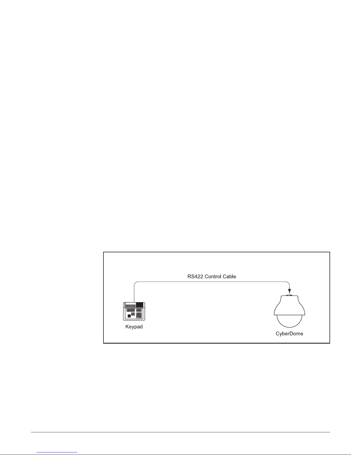
Operation Requirements
The CyberDome contains a built-in receiver that decodes commands originating from a KTD-404/
KTD-304 or KTD-400/KTD-300 controller keypad. A minimum of one keypad is required for
operation. See Figure 1. From the keypad, an operator can pan the CyberDome 360o, tilt it
90o, control its motorized lens, find preset positions, and initiate predefined camera tours.
Figure 1: Basic Application
A06-8SG0/B/April2006/1033921C
5
Introduction CyberDome Series Installation Manual
Cable Requirements
For operation, CyberDomes require video, power and data cables as described below:
1) The video cable carries the video signal to the remote viewing site. If sending video via
coaxial cable, a 75-ohm coaxial cable is typically used. If sending video via twisted-pair
cable, an unshielded, 22 gauge (0.64 mm) twisted-pair cable is needed.
2) The 24VAC cable powers the CyberDome and the camera. To determine cable size, refer
to the Power Cable Size and Length subsection of the Introduction.
3) The RS422 control cable carries commands from the Digiplex keypad to the CyberDome.
An unshielded, two-conductor, twisted-pair cable is required. Recommended cable size
is 22 gauge (0.64 mm).
NOTE: When using the UTP interface modules, the unshielded twisted-pair video and RS422 control
wires can share the same wire jacket, but must remain as separate twisted pairs.
Power Requirements
CAUTION!
For optimal video performance, all CyberDomes must be powered from an isolated 24 VAC power
source—fused outputs are not adequate. Allowable voltage range is 20 to 28 volts.
All domes require a 24VAC power supply that provides isolated outputs to operate the domes’
pan/tilt drive, camera, and optional heater/fan (E Option). The total power requirement varies
depending on the model of the CyberDome.
Dome power requirements (at 24 VAC):
• All domes without a heater/fan require 16 VA
• 7-inch domes with heater/fan require 51 VA
• Heavy-duty domes with heater/fan require 68 VA.
Power Cable Size and Length
It is important to choose the proper gauge of the cable that supplies 24 volts to the CyberDome.
An inadequate gauge will cause a voltage drop resulting in improper operation.
Table 1 gives the recommended cable lengths of varying wire gauges for a CyberDome with a
color camera. Note that the heater and fan (E Option) reduces maximum cable length substantially.
Table 1. Recommended maximum cable lengths.
Maximum Cable Length
Wire Gauge
(awg) (mm2) Feet Meters Feet Meters Feet Meters
10 2.60 3000 915 900 274 630 192
12 2.05 1900 580 570 174 400 122
14 1.62 1200 365 360 110 250 76
16 1.29 750 230 230 70 160 49
18 1.02 465 142 145 44 100 30
200.812909090276219
220.641855660184012
All Domes
without Heater/Fan
(16VA)
7-inch Domes
with Heater/Fan
(51VA)
Heavy-duty Domes
with Heater/Fan
(91VA)
6
A06-8SG0/B/April2006/1033921C
CyberDome Series Installation Manual Housing Installation
HOUSING INSTALLATION
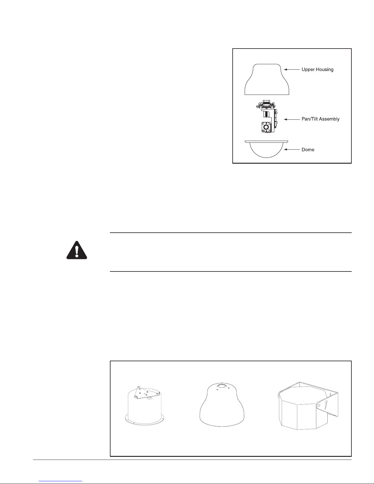
A complete CyberDome consists of an upper housing, a pan/tilt assembly with a built-
Figure 2: A Complete CyberDome
in receiver and camera, and an acrylic dome.
See Figure 2.
In General
The method of installation depends on which
upper housing is being used. Installation involves securing the upper housing, making
cable connections, mounting the pan/tilt assembly, and fastening the acrylic dome.
The Interface Module
All CyberDome cable connections (video,
RS422, and 24VAC) are made to one of
several interface modules. When sending
video via coaxial cable, connections are made to a coaxial interface module. When sending
video via unshielded twisted-pair wire, connections are made to a UTP interface module.
There are two CyberMount interface modules—one for coaxial video transmission and one for
UTP video transmission. These are integrated into the CyberMount. There are also two
CyberDome interface modules. Again, one for coaxial and one for UTP video transmission.
These are used for all other installations, except for the heavy-duty dome. Which has its own
integrated coaxial/UTP interface module.
CAUTION!
Even though a complete CyberDome assembly weighs less than 5 lb (HD less than 15 lb), for
safety reasons GE Security recommends that all mechanical components used to support the
CyberDome assembly be able to support a 35 lb (15.88 kg) load. The heavy-duty dome assembly
must be able to support a 75 lb (35.02 kg) load.
Installation procedures are listed in separate sections for each housing style. Determine
which style is being used and proceed directly to the appropriate section.
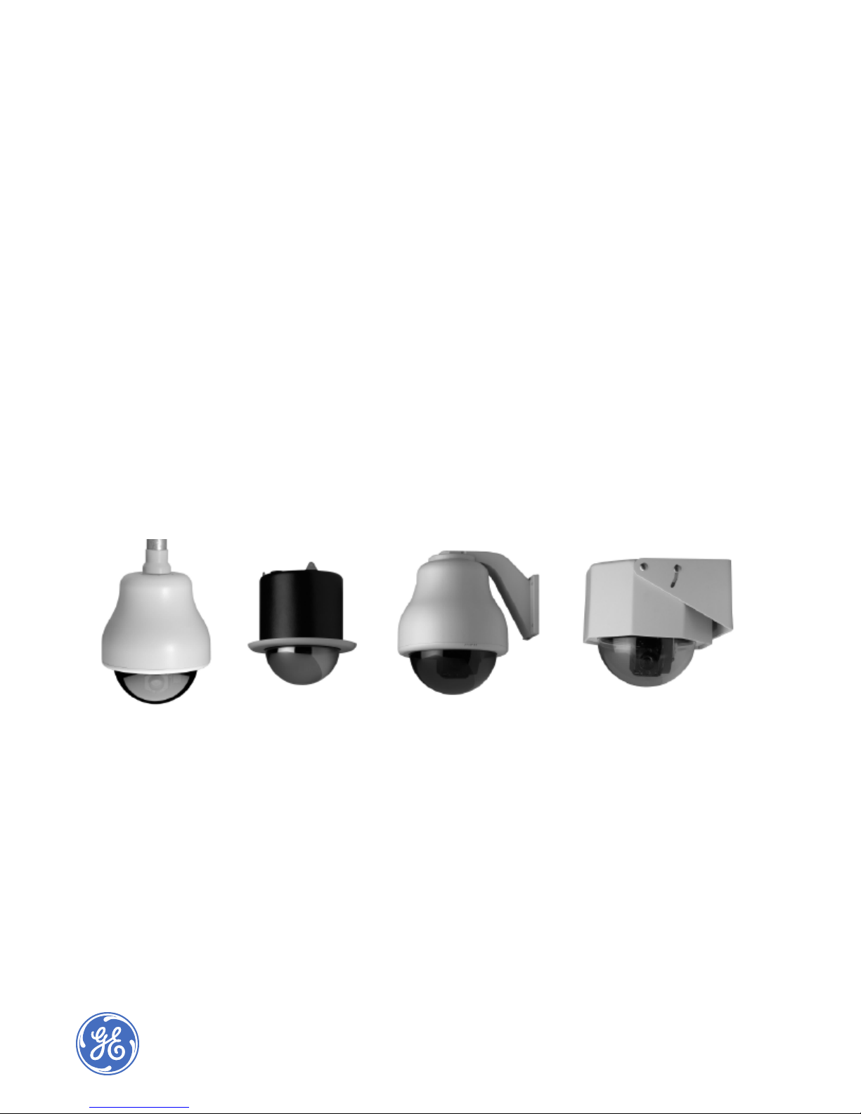
The upper housing is available in three styles (see Figure 3):
• The flush-mount housing is designed for false ceiling applications. Refer to page 8.
• The 7-inch (formally 8-inch) pendant-mount housing is designed to suspend from the end
of a 1.25 in. NPT pipe or a variety of arm brackets. Refer to page 17.
• The heavy-duty housing is designed for areas where the CyberDome might be susceptible
to vandalism—it contains its own reinforced mounting bracket. Refer to page 28.
Figure 3: CyberDome Housing Styles
6-inch Flush-mount
A06-8SG0/B/April2006/1033921C
Housing
7-inch Pendant-mount
Housing
Heavy-duty
Housing
7
Housing Installation CyberDome Series Installation Manual
6-inch Flush-mount Housing Installation
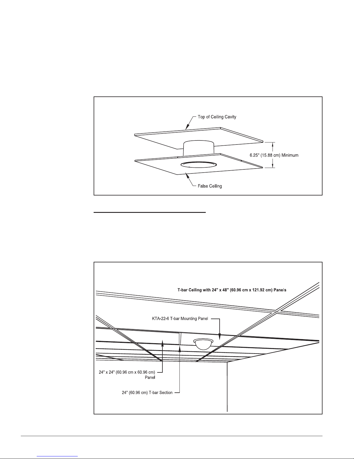
The indoor flush-mount housing can be installed into most types of ceilings, provided there is
sufficient clearance for the unit. See Figure 4. The method of installation depends on the type
of ceiling into which the CyberDome is being mounted. Methods are:
• Method 1 – Into T-bar ceilings
• Method 2 – Into non-removable false ceilings (page 11)
• Method 3 – With superstructure attachment (page 15)
Figure 4: False Ceiling Clearance
(page 8)
Method 1: Installation Into T-Bar Ceilings
A T-bar type ceiling consists of a metal grid, which is used to suspend removable panels.
See Figure 5. The panels will be either 24 in. x 24 in. (60.96 cm x 60.96 cm) or 24 in. x 48 in.
(60.96 cm x 121.92 cm). Installation into this type of ceiling requires a KTA-22-6 T-bar Mounting Panel (24 in. x 24 in., i.e., 60.96 cm x 60.96 cm) or a KTA-24-6 T-Bar Support Kit (refer to
Appendix A). The KTA-22-6 was formerly the KTA-00-6, and the KTA-24-6 the KTA-10-6.
Figure 5: T-Bar Ceiling with Mounting Panel
8
A06-8SG0/B/April2006/1033921C
CyberDome Series Installation Manual Housing Installation
For installation, proceed as follows:
CAUTION!
DO NOT provide power to the housing until all installation steps are complete.
Step 1) Determine where the CyberDome is to be located and remove the ceiling panel at
that location.
Step 2) If the removed ceiling panel is the smaller 24 in. x 24 in. (60.96 cm x 60.96 cm)
size, continue with step 3.
If the panel is the larger 24 in. x 48 in. (60.96 cm x 121.92 cm) size, cut the panel
into two 24 in. x 24 in. (60.96 cm x 60.96 cm) sections and install a 24 in.
(60.96 cm) T-bar across the center of the ceiling opening. Refer to Appendix A:
KTA-24-6 and KTA-24-8/KTA-10-8 T-Bar Support Kits. See Figure 5.
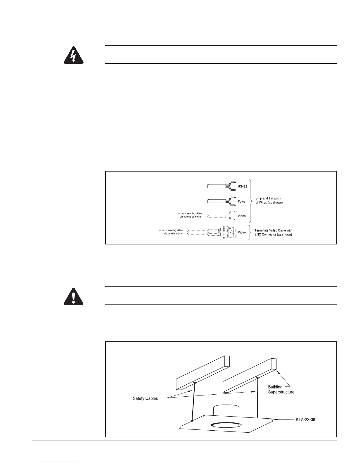
Step 3) Feed the video, 24VAC, and RS422 control cables through the ceiling to the
vacated panel location.
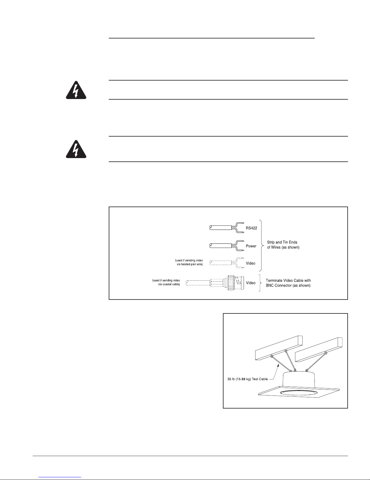
Step 4) Prepare the cables as shown in Figure 6.
Figure 6: Preparing the Cables
Step 5) Attach the CyberDome housing to the KTA-22-6 panel using the three 10-32
flathead screws provided.
Step 6) Place the housing/panel assembly in the ceiling.
CAUTION!
Each safety cable in step 7 (below) must be able to support a 35 lb (15.88 kg) load.
Step 7) Attach two metal safety cables between the KTA-22-6 and the ceiling’s super-
structure to insure that the mounting panel cannot fall. See Figure 7. Holes are
located in each side of the panel for this purpose.
Figure 7: Attaching the Safety Cables
A06-8SG0/B/April2006/1033921C
9
Housing Installation CyberDome Series Installation Manual
CAUTION!
DO NOT connect the 24VAC power cable to the video or RS422 connection in step 8 (below), or the
CyberDome will be damaged.
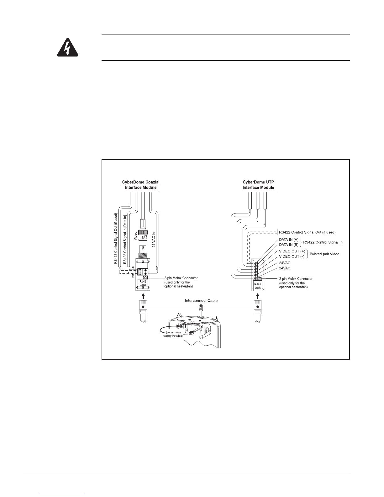
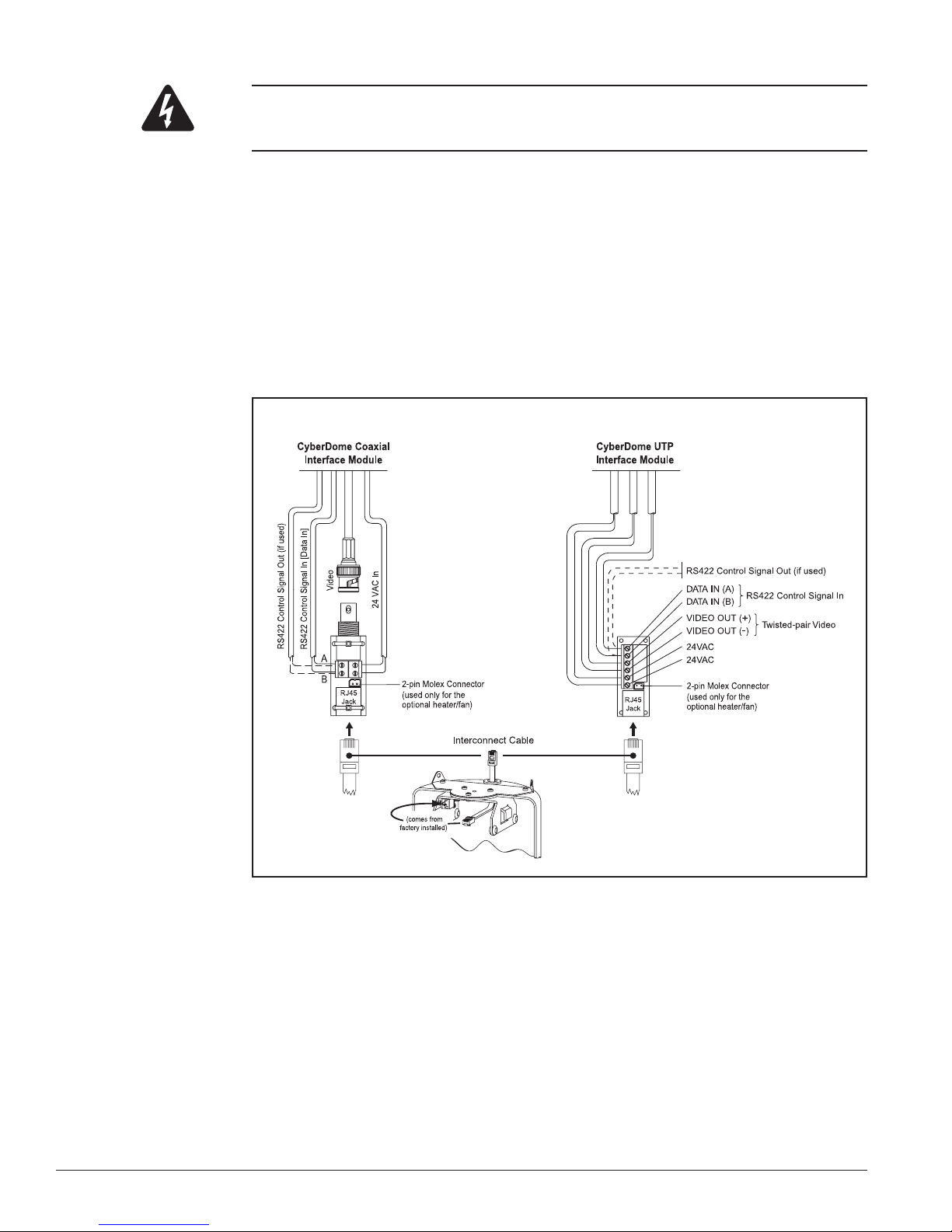
Step 8) Connect the prepared cables to the interface module. See Figure 8.
There are two versions of the CyberDome interface module depending on whether
video is being sent via coaxial cable (CyberDome Coaxial Interface Module) or
unshielded twisted-pair wire (CyberDome UTP Interface Module).
NOTE: When using the CyberDome UTP Interface Module, the unshielded twistedpair video and RS422 control wires can share the same wire jacket, but must remain
as separate twisted pairs.
Step 9) Insert the interconnect cable from the CyberDome into the RJ45 jack in the inter-
face module. See Figure 8.
Figure 8: Connecting the Cables to Either CyberDome Interface Module
Step 10) Reinstall any removed ceiling panels.
Step 11) Proceed to RS422 Termination on page 31.
10
A06-8SG0/B/April2006/1033921C
CyberDome Series Installation Manual Housing Installation
Method 2: Installation Into A Non-Removable False Ceiling
Note:
This method of installation should be used only when the false ceiling is sturdy enough to support
the weight of a complete CyberDome assembly.
The KTA-23-6 Ceiling Ring (formerly the KTA-01-6) is used to install the flush-mount housing
in a non-removable type false ceiling. The ring allows installation by a single person and does
not require that the person enter the ceiling cavity (except for cable routing).
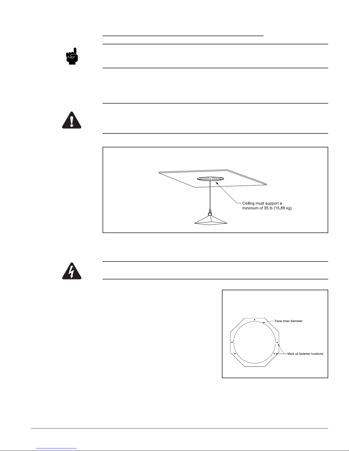
CAUTION!
The KTA-23-6 distributes the weight of the CyberDome around the perimeter of the ceiling cutout.
The ceiling must be strong enough to support a minimum of 35 lb (15.88 kg), as illustrated in
Figure 9.
Figure 9: Minimum Ceiling Strength
To install the upper housing using the KTA-23-6 Ceiling Ring, proceed with the following steps:
CAUTION!
DO NOT provide power to the housing until all installation steps are complete.
Step 1) Hold the ceiling ring in the de-
sired location on the ceiling with
Figure 10: Fastener Hole Locations
the flat surface facing away from
the ceiling.
Step 2) Use a pencil to trace the inside
of the ceiling ring and to mark
all five fastener hole locations (as
shown in Figure 10).
A06-8SG0/B/April2006/1033921C
11
Housing Installation CyberDome Series Installation Manual
CAUTION!
Before drilling or cutting holes, be certain there is a minimum of 6.25 in. (15.88 cm) of clearance
above all installation holes and that no electrical cables, pipes, or other obstacles are present.
Step 3) Using a 3⁄16 in. drill bit, drill all five fastener holes. Be certain that all holes are
drilled perpendicular to the ceiling.
Step 4) Cut a hole in the ceiling using the penciled outline as a guide.
Step 5) Bend the ceiling ring just enough to clear the hole. Bend it flat again and place it
in the ceiling with its smooth side down and its mounting holes aligned with the
drilled holes in the ceiling.
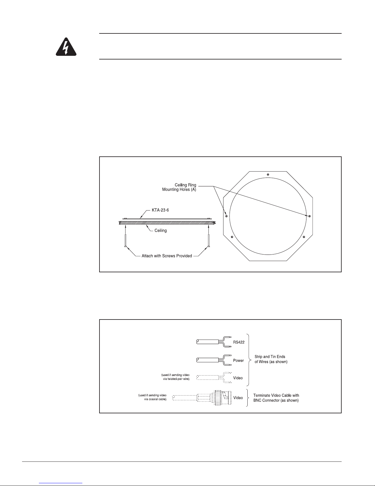
Step 6) Using the mounting holes (A in Figure 11), secure the ceiling ring in place with
two of the 6-32 x 2 in. flathead screws provided. Tighten the screws enough to
draw them flush with the ceiling surface.
Figure 11: Mounting the Ceiling Ring
Step 7) Feed the video, 24VAC, and RS422 control cables from the ceiling through the
hole.
Step 8) Prepare the cables as shown in Figure 12.
Figure 12: Preparing the Cables
12
A06-8SG0/B/April2006/1033921C
CyberDome Series Installation Manual Housing Installation
CAUTION!
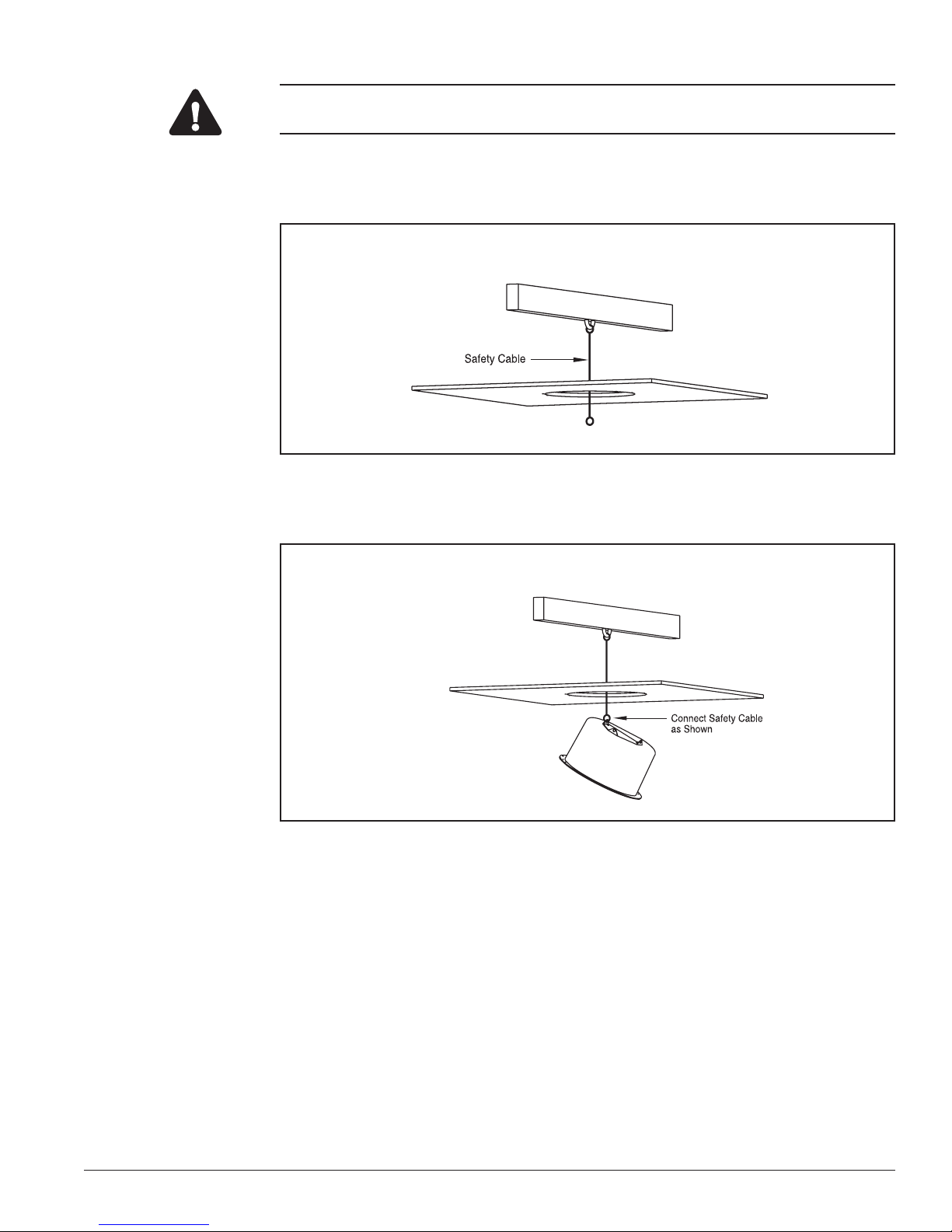
The safety cable in step 9 (below) must be able to support a 35 lb (15.88 kg) load.
Step 9) Attach a 35 lb (15.88 kg) test metal safety cable to the ceiling’s superstructure
and feed it through the hole. See Figure 13.
Figure 13: Attaching the Safety Cable to the Superstructure
Step 10) Bring the housing to just below the hole opening and attach the safety cable. See
Figure 14.
Figure 14: Connecting the Safety Cable to the Housing
A06-8SG0/B/April2006/1033921C
13
Housing Installation CyberDome Series Installation Manual
CAUTION!
DO NOT connect the 24VAC power cable to the video or RS422 connection in step 11 (below), or the
CyberDome will be damaged.
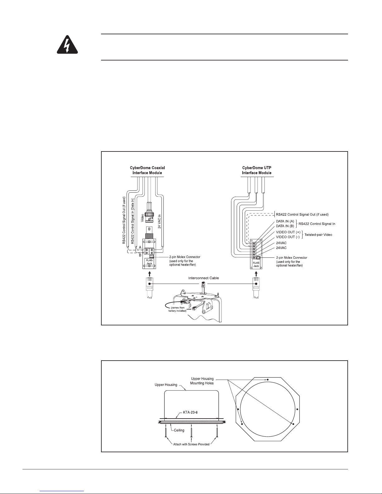
Step 11) Connect the prepared cables to the interface module. See Figure 15.
There are two versions of the CyberDome interface module depending on whether
video is being sent via coaxial cable (CyberDome Coaxial Interface Module) or
unshielded twisted-pair wire (CyberDome UTP Interface Module).
NOTE: When using the CyberDome UTP Interface Module, the unshielded twistedpair video and RS422 control wires can share the same wire jacket, but must remain
as separate twisted pairs.
Step 12) Insert the interconnect cable from the CyberDome into the RJ45 jack in the inter-
face module. See Figure 15.
Figure 15: Connecting the Cables to Either CyberDome Interface Module
Step 13) Push the CyberDome upper housing through the hole and position the housing’s
Figure 16: Securing the Upper Housing
Step 14) Proceed to RS422 Termination on page 31.
14
three mounting holes to match those in the ceiling. Use the remaining three
screws to secure the housing to the ring.
A06-8SG0/B/April2006/1033921C
CyberDome Series Installation Manual Housing Installation
Method 3: Installation By Attaching The Housing To The Superstructure
When a non-removable false ceiling is not sturdy enough to support the weight of the CyberDome, the housing must be suspended from the ceiling superstructure with metal cables.
This normally requires two installers, one to hold the upper housing in place while the second
attaches and tightens the cables in the ceiling cavity. Proceed as follows:
CAUTION!
DO NOT provide power to the housing until all installation steps are complete.
Step 1) Determine the desired location on the ceiling for mounting the CyberDome and
use a pencil to trace a 6 3⁄8 in. (16.19 cm) diameter hole outline.
CAUTION!
Before drilling or cutting holes, be certain there is a minimum of 6.5 in. (16.51 cm) of clearance
above all installation holes and that no electrical cables, pipes, or other obstacles are present.
Step 2) Cut the hole in the ceiling.
Step 3) Feed the video, 24VAC, and RS422 control cables to the hole location and pre-
pare them for connection. See Figure 17.
Figure 17: Preparing the Cables
Step 4) Push the upper housing
through the hole and attach
securely to the ceiling’s superstructure with 35 lb
(15.88 kg) test cables, as
shown in Figure 18.
Figure 18: Attaching the Test Cables
A06-8SG0/B/April2006/1033921C
15
Housing Installation CyberDome Series Installation Manual
CAUTION!
DO NOT connect the 24VAC power cable to the video or RS422 connection in step 5 (below), or the
CyberDome will be damaged.
Step 5) Connect the prepared cables to the interface module. See Figure 19.
There are two versions of the CyberDome interface module depending on whether
video is being sent via coaxial cable (CyberDome Coaxial Interface Module) or
unshielded twisted-pair wire (CyberDome UTP Interface Module).
NOTE: When using the CyberDome UTP Interface Module, the unshielded twistedpair video and RS422 control wires can share the same wire jacket, but must remain
as separate twisted pairs.
Step 6) Insert the interconnect cable from the CyberDome into the RJ45 jack in the inter-
face module. See Figure 19.
Figure 19: Connecting the Cables to Either CyberDome Interface Module
Step 7) Proceed to RS422 Termination on page 31.
16
A06-8SG0/B/April2006/1033921C
 Loading...