

GE PVS21KSEBFSS, PGS25KSEAFSS, CWS21SSEBFSS Owner’s Manual
N
L..
LL.
E
0
0
L..
0
GEAppliances.com
Safety Instructions ............ 2, 3
Operating Instructions
Additional Features .................. 9
Automatic Icemaker ............. 12,13
Care and Cleaning .............. 13,14
Controls .......................... 4,5
Crispers and Pans .................. 10
Freezer ............................ 11
Replacing the Light Bulbs ........... 15
Shelves and Bins .................. 8, 9
Water Dispenser ................... 13
Water Filter ......................... 6
Water Filter ......................... 7
Installation Instructions
Installing the Anti-Tip
Floor Bracket ................... 19, 20
Installing the Refrigerator ....... 21-25
Installing the Water Line ........ 34-35
Preparing to Install
the Refrigerator .................... 18
Removing and Replacing the
Freezer Drawer ................ 26, 27
Reversing the Door Swing ...... 28-30
Removing and Replacing
the Doors ..................... 31-33
Trim Kits and Decorator Panels.... 16, 17
Models 27 and25
Congelateur inferieur
Refr
La section francaise commence a la page 45
Congelador inferior
La seccion en espahol empieza en /a pagina 89
rs
L.
Troubleshooting Tips ...... 37-41
Normal Operating Sounds .......... 37
Consumer Support
Consumer Support ........ Back Cover
Performance Data Sheet ........... 43
State of California Water
Treatment Device Certificate ........ 44
Warranty for Canadian
Customers ......................... 42
Warranty for U.S.Customers ........ 41
Write the model and serial
numbers here:
Model #
Serial #
These numbers are found onalabel
located on upper left or right side of
refrigerator compartment
200D9366P026 49-60675-2 07-74 GE
IMPORTANT SAFETYINFORMATION.
READALL INSTRUCTIONSBEFOREUSING.
A WARNING!
Use this appliance only for its intended purpose as described in this Owner's Manual.
SAFETYPRECAUTIONS
When using electrical appliances, basic safety precautions should be followed, including the following.
This refrigerator must be properly installed
and located in accordance with the Installation
Instructions before it is used.
Do not allow children to climb, stand or hang
on the shelves in the refrigerator. They could damage
the refrigerator and seriously injure themselves.
Do not touch the cold surfaces in the freezer
compartment when hands are damp or wet.
Skin may stick to these extremely cold surfaces.
Do not store or use gasoline or other flammable
vapors and liquids in the vicinity of this or any other
appliance.
Keep fingers out of the "pinch point" areas;
clearances between the doors and between the
doors and cabinet are necessarily small. Be careful
closing doors when children are in the area.
, In refrigerators with automatic icemakers, avoid
contact with the moving parts of the ejector
mechanism, or with the heating element that
releases the cubes. Do not place fingers or hands
on the automatic icemaking mechanism while the
refrigerator is plugged in.
Unplug the refrigerator before cleaning and making
repairs,
NOTE: We strongly recommend that any servicing be
performed by a qualified individual,
Setting either or both controls to 0 (off) does not
remove power to the light circuit,
Do not refreeze frozen foods which have thawed
completely.
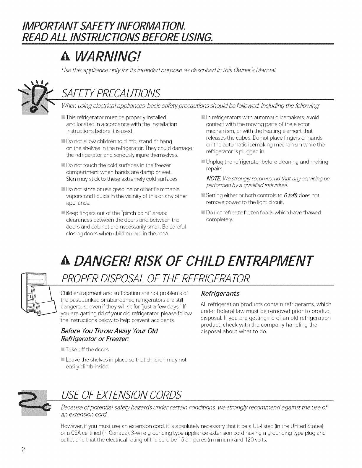
A DANGER! RISK OF CHILD ENTRAPMENT
PROPERDISPOSALOF THEREFRIGERATOR
Child entrapment and suffocation are not problems of
the past. Junked or abandoned refrigerators are still
dangerous...even if they will sit for 'lust a few days." If
you are getting rid of your old refrigerator, please follow
the instructions below to help prevent accidents.
Before You Throw Away Your Old
Refrigerator or Freezer:
Take off the doors.
Leave the shelves in place so that children may not
easily climb inside,
Refrigerants
All refrigeration products contain refrigerants, which
under federal law must be removed prior to product
disposal. If you are getting rid of an old refrigeration
product, check with the company handling the
disposal about what to do.
USEOFEXTENSIONCORDS
Because of potential safety hazards under certain conditions, we strongly recommend against the use of
an extension cord.
However, if you must use an extension cord, it is absolutely necessary that it be a UL-listed (in the United States)
or a CSA certified (in Canada), 3-wire grounding type appliance extension cord having a grounding type plug and
outlet and that the electrical rating of the cord be 15 amperes (minimum) and 120 volts.
GEApplMnces.com
A WARNING!
HOW TOCONNECTELECTRICITY
Do not.,under any circumstances, cut or remove the third (ground) prong from the power cord.
For personal safety, this appliance must be properly grounded.
The power cord of this appliance is equipped with a
3-prong (grounding) plug which mates with a standard
3-prong (grounding) wall outlet to minimize the
possibility of electric shock hazard from this appliance,
Have the wall outlet and circuit checked by a qualified
electrician to make sure the outlet is properly grounded,
Where a standard 2-prong wall outlet is encountered, it
is your personal responsibility and obligation to have it
replaced with a properly grounded 3-prong wall outlet,
The refrigerator should always be plugged into its own
individual electrical outlet which has a voltage rating
that matches the rating plate,
This provides the best performance and also prevents
overloading house wiring circuits which could cause a
fire hazard from overheated wires,
Never unplug your refrigerator by pulling on the power
cord, Always grip plug firmly and pull straight out from
the outlet,
Repair or replace immediately all power cords that have
become frayed or otherwise damaged, Do not use a
cord that shows cracks or abrasion damage along its
length or at either end,
When moving the refrigerator away from the wall, be
careful not to roll over or damage the power cord,
READAND FOLLOW THIS.SAFETYINFORMATIONCAREFULLY.
SAVETHESEINSTRUCTIONS
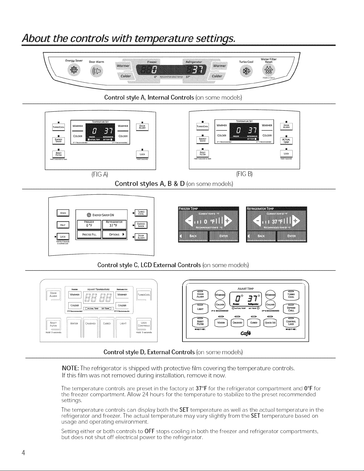
About the controls with temperature settin s.
Control style A, Internal Controls (on some models)
WARMER T_MPERATURE SET WARMER
(FIGA) (FIG B)
Control styles A, B & D (on some models)
_ ENERGY SAVER ON
_REEZER I REFRIGERATOR
F_q
Control style C, LCD External Controls (on some models)
_
iL...................
@ ......o-__o........
HO_d 3 _.e onds No[d 3 _nd
Control style D, External Controls (on some models)
NOTE: The refrigerator is shipped with protective film covering the temperature controls.
If this film was not removed during installation, remove it now.
The temperature controls are preset in the factory at 37°F for the refrigerator compartment and 0°F for
the freezer compartment, Allow 24 hours for the temperature to stabilize to the preset recommended
settings,
The temperature controls can display both the SET temperature as well as the actual temperature in the
refrigerator and freezer, The actual temperature may vary slightly from the SET temperature based on
usage and operating environment,
Setting either or both controls to OFF stops cooling in both the freezer and refrigerator compartments,
but does not shut off electrical power to the refrigerator,
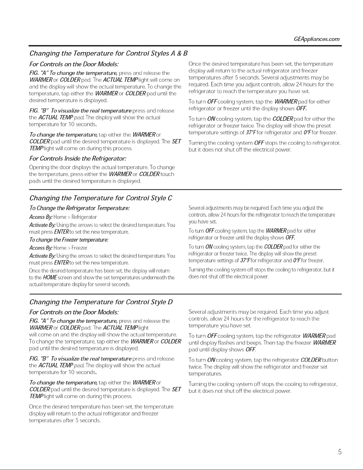
Changing the Temperature for Control Styles A & B
For Controls on the Door Models:
FIG. "A" To change the temperature, press and release the
WARMER or COLDER pad, The ACTUAL TEMPlight will co me on
and the display will show the actual temperature, To change the
temperature, tap either the WARMERor COLDERpad until the
desired temperature is displayed,
FIG. "B" To visualize the real temperature press and release
the ACTUAL TEMPpad. The display will show the actual
temperature for 10 seconds.
To change the temperature, tap either the WARMER or
COLDERpad until the desired temperature is displayed, The SET
TEMPlight will come on during this process,
For Controls Inside the Refrigerator:
Opening the door displays the actual temperature. To change
the temperature, press either the WARMERor COLDERtouch
pads until the desired temperature is displayed.
Changing the Temperature for Control Style C
To Change the Refrigerator Temperature:
Access By:Home > Refrigerator
Activate By:Usingthe arrows to selectthe desired temperature. You
must pressENTERtoset the new temperature.
Tochange the Freezertemperature:
Access By:Home > Freezer
Activate By:Usingthe arrows to selectthe desired temperature. You
must pressENTERtoset the new temperature.
Once the desired temperature has been set,the display will return
to the HOMEscreen and show the set temperatures underneath the
actual temperature display for several seconds.
GEAppliances.com
Once the desired temperature has been set, the temperature
display will return to the actual refrigerator and freezer
temperatures after 5 seconds. Several adjustments may be
required. Each time you adjust controls, allow 24 hours for the
refrigerator to reach the temperature you have set.
To turn OFFcooling system, tap the WARMERpad for either
refrigerator or freezer until the display shows OFF.
To turn ONcooling system, tap the COLDERpad for either the
refrigerator or freezer twice. The display will show the preset
temperature settings of 37°Ffor refrigerator and O°Ffor freezer.
Turning the cooling system OFFstops the cooling to refrigerator,
but it does not shut off the electrical power,
Severaladjustments may berequired, Each timeyou adjust the
controls, allow 24 hours for the refrigerator to reach the temperature
you have set,
Toturn OFFcooling system,tap the WARMERpad for either
refrigerator or freezer until the display shows OFF.
Toturn ONcooling system,tap the COLDERpad for either the
refrigerator or freezer twice, Thedisplay will show the preset
temperature settings of 37°Ffor refrigerator and O°Ffor freezer,
Turning the cooling system off stops the cooling to refrigerator, but it
does not shut offthe electrical power,
Changing the Temperature for Control Style D
For Controls on the Door Models:
FIG. "A" To change the temperature, press and release the
WARMERor COLDERpad. The ACTUAL TEMPlight
will come on and the display will show the actual temperature.
To change the temperature, tap either the WARMERor COLDER
pad until the desired temperature is displayed.
FIG. "B" To visualize the real temperature press and release
the ACTUAL TEMPpad. The display will show the actual
temperature for 10 seconds.
To change the temperature, tap either the WARMER or
COLDERpad until the desired temperature is displayed. The SET
TEMPlight will come on during this process.
Once the desired temperature has been set, the temperature
display will return to the actual refrigerator and freezer
temperatures after 5 seconds.
Several adjustments may be required, Each time you adjust
controls, allow 24 hours for the refrigerator to reach the
temperature you have set,
To turn OFFcooling system, tap the refrigerator WARMERpad
until display flashes and beeps, Then tap the freezer WARMER
pad until display shows OFF,
To turn ONcooling system, tap the refrigerator COLDERbutton
twice. The display will show the refrigerator and freezer set
temperatures.
Turning the cooling system off stops the cooling to refrigerator,
but it does not shut off the electrical power.
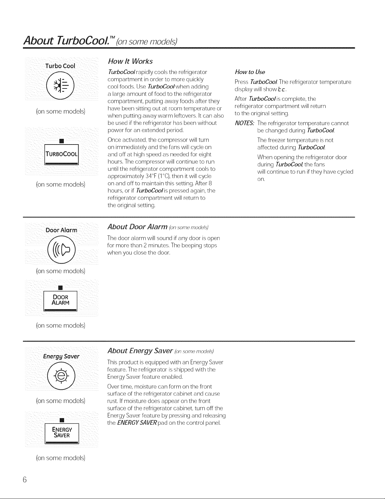
About TurboCool. TM som mod ,'s
How It Works
TurboCoolrapidly cools the refrigerator
compartment in order to more quickly
cool foods, Use TurboCoolwhen adding
a large amount of food to the refrigerator
compartment, putting away foods after they
(on some models)
iii°R°°c°°____z
/ iiii_i_/_i_iii_i_i_ i_i_iii_iII
(onsome models)
have been sitting out at room temperature or
when putting away warm leftovers, It can also
be used if the refrigerator has been without
power for an extended period,
Once activated, the compressor will turn
on immediately and the fans will cycle on
and off at high speed as needed for eight
hours, The compressor will continue to run
until the refrigerator compartment cools to
approximately 34°F (1°C),then it will cycle
on and off to maintain this setting, After 8
hours, or if TurboCoolis pressed again, the
refrigerator compartment will return to
the original setting,
How to Use
Press TurboCooZ The refrigerator temperature
display will show be,
After TurboCoolis complete, the
refrigerator compartment will return
to the original setting,
NOTES: The refrigerator temperature cannot
be changed during TurboCoo!
The freezer temperature is not
affected during TurboCooZ
When opening the refrigerator door
during TurboCoo/, the fans
will continue to run if they have cycled
on,
Door Alarm
(on some models)
DOOR
ALARM
(on some models)
(on some models)
i i i i i _ii
ENERGV
SAwR
About Door Alarm (onsomemodel.s)
The door alarm will sound if any door is open
for more than 2 minutes, The beeping stops
when you close the door,
About Energy Saver (onsom_modal.s)
This product is equipped with an Energy Saver
feature, The refrigerator is shipped with the
Energy Saver feature enabled,
Over time, moisture can form on the front
surface of the refrigerator cabinet and cause
rust, If moisture does appear on the front
surface of the refrigerator cabinet, turn off the
Energy Saver feature by pressing and releasing
the ENERGYSA VERpad on the control panel,
(on some models)
About the water filter. (onsomemodels} GEAppliances.com
Water filter cartridge
The water filter cartridge is located in the back upper right corner of
the refrigerator compartment.
When to replace the filter on models I!_
with a replacement indicator light
There isa replacement indicator light for the water filter cartridge
on the dispenser. This light will turn orange to
tell you that you need to replace the filter soon.
The filter cartridge should be replaced when the replacement
indicator light turns red or ifthe flow of water to the dispenser or
icemaker decreases.
When to replace the filter on models
without a replacement indicator light
The filter cartridge should be replaced every six months
or earlier if the flow of water to the dispenser or
icemaker decreases.
Removing the filter cartridge
Ifyou are replacing the cartridge, first remove the old one
by slowly turning it to the left. Do not pull down on the cartridge, A
small amount of water may drip down,
CAUTION: To reduce the risk associated with property damage due
to water leakage, read and follow instructions before installation
and use of this system, Installation and use MUST comply with all
state and local plumbing codes,
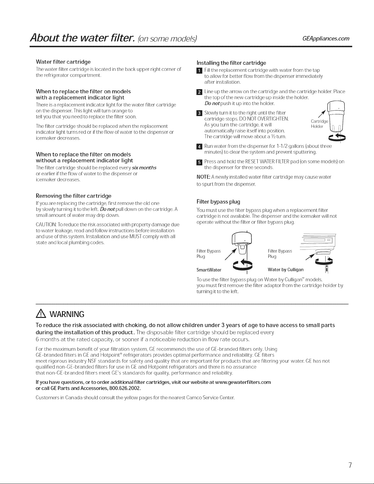
Installing the filter cartridge
El Fillthe replacement cartridge with water from the tap
to allow for better flow from the dispenser immediately
after installation.
Line up the arrow on the cartridge and the cartridge holder. Place
the top of the new cartridge up inside the holder.
Slowly turn it to the right until the filter
cartridge stops. DO NOT OVERTIGHTEN.
Do notpush it up into the holder. Ca/_c,__ _
As you turn the cartridge, it will
automatically raise itself into position.
The cartridge will move about a YJturn.
Run water from the dispenser for 1-1/2 gallons (about three
E!
minutes) to clear the system and prevent sputtering.
Press and hold the RESETWATERFILTERpad (on some models) on
m
the dispenser for three seconds.
NOTE: A newly installed water filter cartridge may cause water
to spurt from the dispenser.
Filter bypass plug
You must use the filter bypass plug when a replacement filter
cartridge is not available. The dispenser and the icemaker will not
operate without the filter or filter bypass plug.
Filter Bypass
Plug
SmartWater
To use the filter bypass plug on Water by Culligan 'Mmodels,
you must first remove the filter adaptor from the cartridge holder by
turning it to the left.
, WatorbyCu,igar,IllI
Filter Bypass
Plug /'_d"
/
,A WARNING
To reduce the risk associated with choking, do not allow children under 3 years of age to have access to small parts
during the installation of this product. The disposable filter cartridge should be replaced every
6 months at the rated capacity, or sooner if a noticeable reduction in flow rate occurs,
For the maximum benefit of your filtration system, GE recommends the use of GE-branded filters only, Using
GE-branded filters in GE and Hotpoint P_refrigerators provides optimal performance and reliability, GE filters
meet rigorous industry NSF standards for safety and quality that are important for products that are filtering your water, GE has not
qualified non-GE-branded filters for use in GE and Hotpoint refrigerators and there is no assurance
that non-GE-branded filters meet GE's standards for quality, performance and reliability,
Ifyou have questions, or to order additional filter cartridges, visit our website at www.gewaterfilters.com
or call GEParts and Accessories, 800.626.2002.
Customers in Canada should consult the yellow pages for the nearest Camco Service Center.
About the shelves and bins.
Not all features are on a// models.
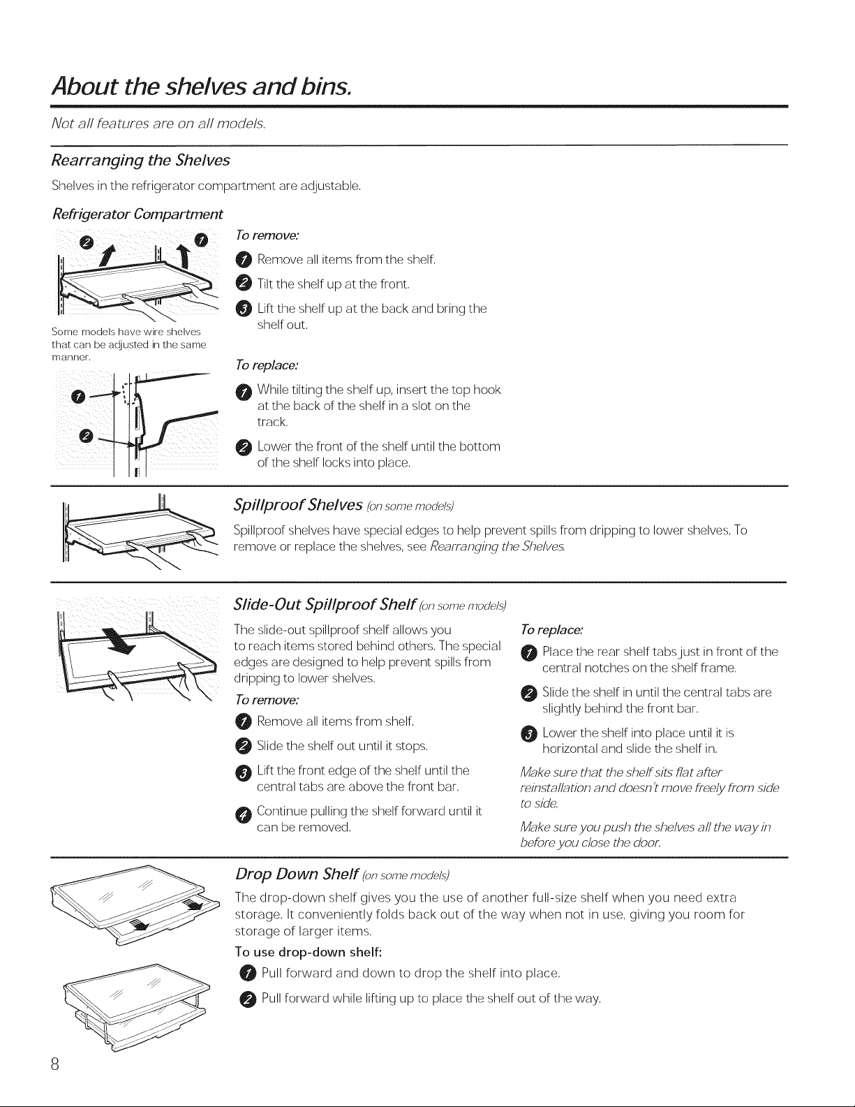
Rearranging the Shelves
Shelves in the refrigerator compartment are adjustable.
Refrigerator Compartment
Toremove:
0 Remove all items from the shelf.
0 Tilt the shelf up at the front.
Lift the shelf up at the back and bring the
Some models have wire shelves
that can be adjusted in the same
manner.
shelf out.
Toreplace:
While tilting the shelf up, insert the top hook
at the back of the shelf in a slot on the
track.
Lower the front of the shelf until the bottom
of the shelf locks into place.
Spfllproof Shelves fon.somemodal.s)
Spillproof shelves have special edges to help prevent spills from dripping to lower shelves. To
remove or replace the shelves, see Rearranging the Shelve_
Slide- Out Spfllproof Shelf fon.s-omemodal.s)
The slide-out spillproof shelf allows you
to reach items stored behind others. The special
edges are designed to help prevent spills from
dripping to lower shelves.
Toremove:
Remove all items from shelf.
Slide the shelf out until it stops.
Lift the front edge of the shelf until the
central tabs are above the front bar.
Continue pulling the shelf forward until it
can be removed.
Toreplace:
Place the rear shelf tabsjust in front of the
central notches on the shelf frame.
Slide the shelf in until the central tabs are
slightly behind the front bar.
Lower the shelf into place until it is
horizontal and slide the shelf in.
M_?kesure that the shelfsits fl_?tafter
reinsmll_tion and doesn't move f/'eely f/'om side
to side,
M_?kesure you push the shelves a# the way in
before you close the door,
Drop Down Sheff (on.somemodel.s)
The drop-down shelf gives you the use of another full-size shelf when you need extra
storage. It conveniently folds back out of the way when not in use, giving you room for
storage of larger items.
To use drop-down shelf:
Pull forward and down to drop the shelf into place.
Pull forward while lifting up to place the shelf out of the way.
About the shelves and bins. GEApplia.ces.com
()//i i ¸¸
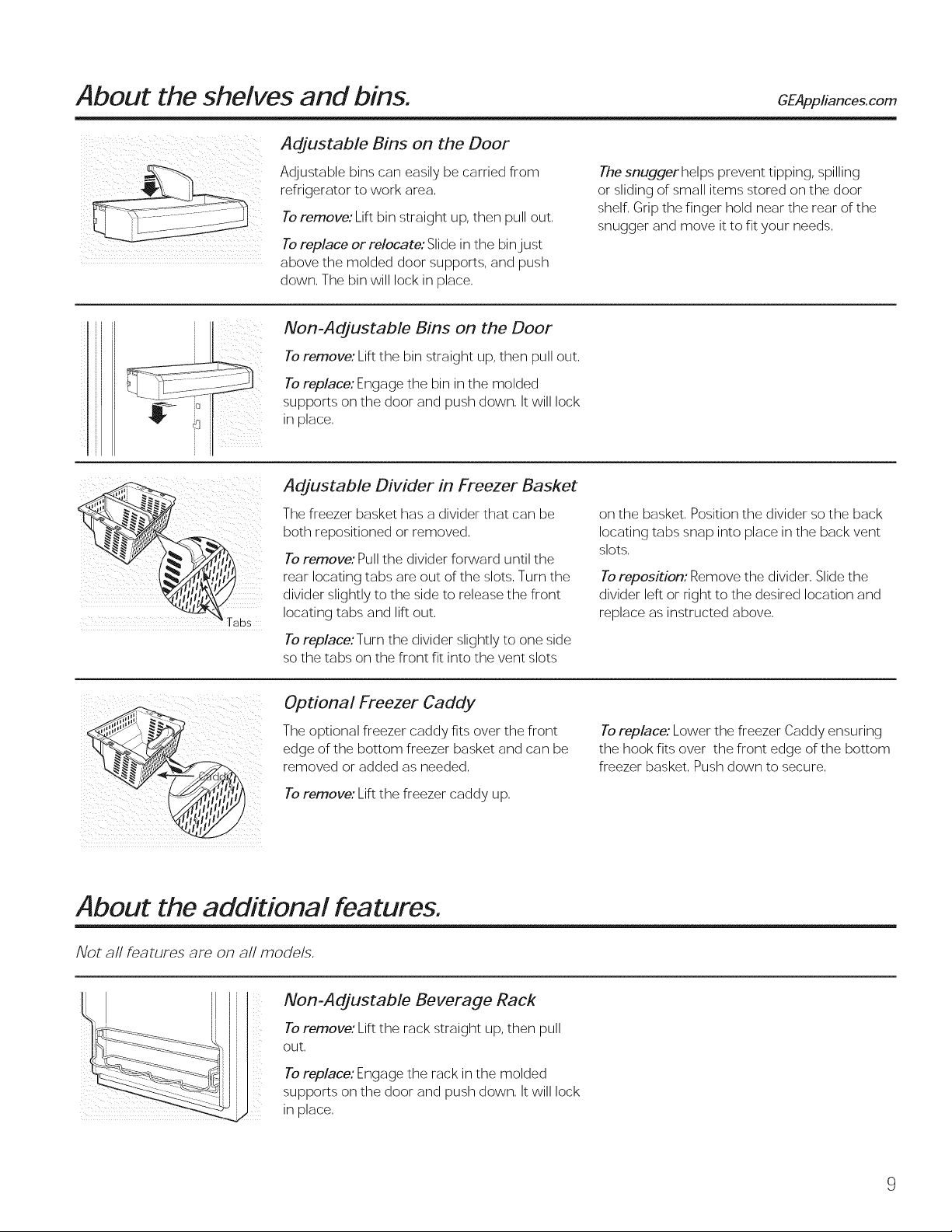
Adjustable Bins on the Door
Adjustable bins can easily be carried from
refrigerator to work area,
Toremove: Lift bin straight up, then pull out.
Toreplace or relocate: Slide in the binjust
above the molded door supports, and push
down. The bin will lock in place.
Non-Adjustable Bins on the Door
Toremove: Lift the bin straight up, then pull out,
Toreplace: Engage the bin in the molded
supports on the door and push down, It will lock
in place,
Adjustable Divider in Freezer Basket
The freezer basket has a divider that can be
both repositioned or removed.
Toremove: Pull the divider forward until the
rear locating tabs are out of the slots. Turn the
divider slightly to the side to release the front
locating tabs and lift out.
The snuggerhelps prevent tipping, spilling
or sliding of small items stored on the door
shelf. Grip the finger hold near the rear of the
snugger and move it to fit your needs.
on the basket. Position the divider so the back
locating tabs snap into place in the back vent
slots.
Toreposition: Remove the divider. Slide the
divider left or right to the desired location and
replace as instructed above.
Toreplace:Turn the divider slightly to one side
so the tabs on the front fit into the vent slots
Optional Freezer Caddy
The optional freezer caddy fits over the front
edge of the bottom freezer basket and can be
removed or added as needed.
Toremove: Lift the freezer caddy up.
About the additional features.
Not all features are on a// models.
Non-Adjustable Beverage Rack
Toremove: Lift the rack straight up, then pull
out.
Toreplace: Engage the rack in the molded
ili
supports on the door and push down. It will lock
in place.
Toreplace: Lower the freezer Caddy ensuring
the hook fits over the front edge of the bottom
freezer basket. Push down to secure.
About the crispers and pans.
Not all features are on a// models.
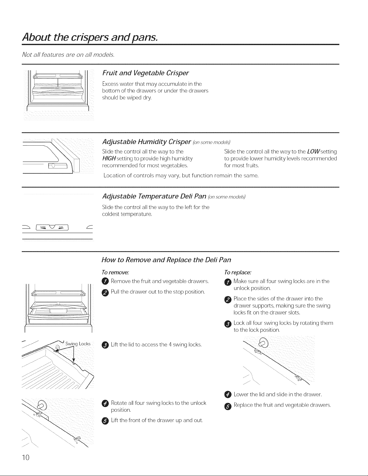
Fruit and Vegetable Crisper
Excess water that may accumulate in the
bottom of the drawers or under the drawers
should be wiped dry.
Adjustable Humidity Crisper (on.somemod_/._)
Slide the control all the way to the Slide the control all the way to the LOWsetting
H/GHsetting to provide high humidity to provide lower humidity levels recommended
recommended for most vegetables, for most fruits.
Location of controls may vary, but function remain the same,
Adjustable Temperature Deft Pan (on.somemodal3)
Slide the control all the way to the left for the
coldest temperature.
_gLocks
How to Remove and Replace the Deli Pan
Toremove:
0 Remove the fruit and vegetable drawers,
0 Pull the drawer out to the stop position,
0
Lift the lid to access the 4 swing locks.
Rotate all four swing locks to the unlock
position.
Lift the front of the drawer up and out,
Toreplace:
Make sure all four swing locks are in the
unlock position.
Place the sides of the drawer into the
drawer supports, making sure the swing
locks fit on the drawer slots.
Lock all four swing locks by rotating them
to the lock position.
Lower the lid and slide in the drawer.
Replace the fruit and vegetable drawers.
10
About the freezer. GEAppliances.com
Not all features are on all models.
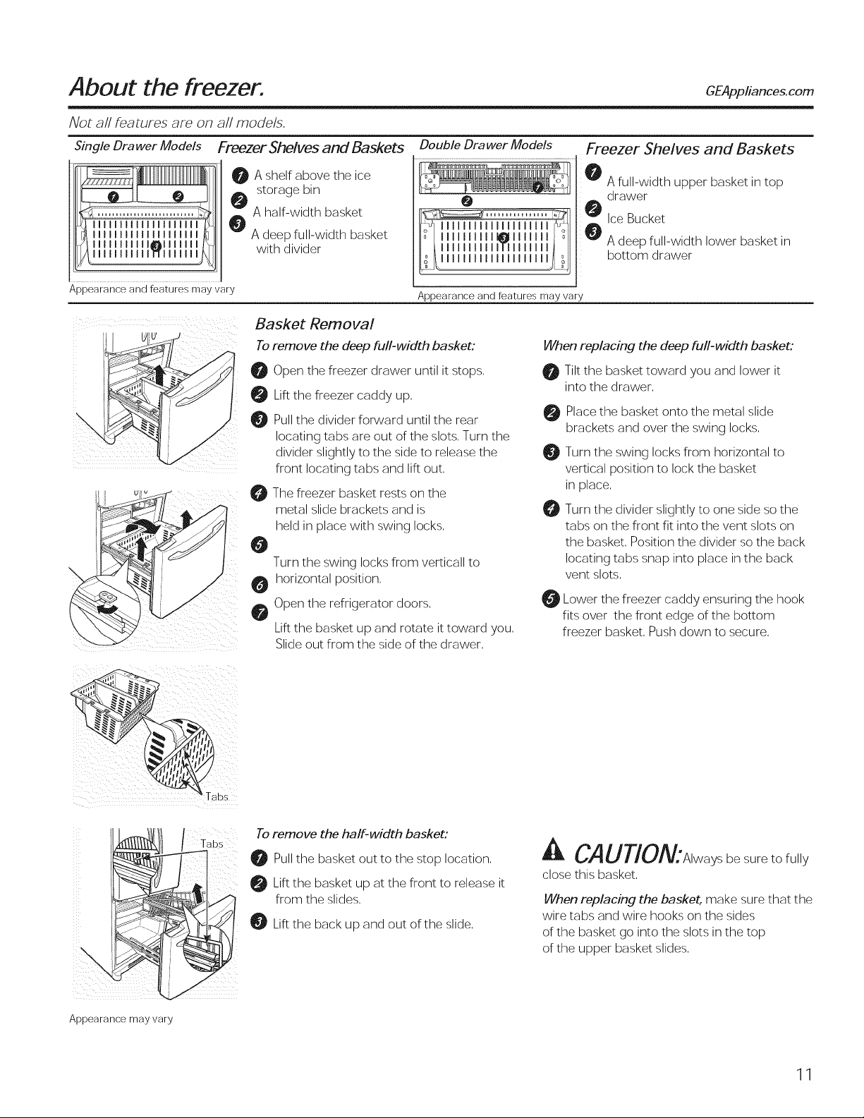
Single Drawer Models Freezer Shelves and Baskets Double Drawer Models Freezer Shelves and Baskets
a
_'_ A full-width upper basket in top
Ice Bucket
_ drawer
A deep full-width lower basket in
bottom drawer
Illlllllllllllllllll
IIIIIIIIIIIIIIIIIIII
lllllllIll
0 A shelf above the ice
storage bin
A half-width basket
A deep full-width basket
with divider
e
11111111111011111111_11
IIIIIIIIIIIfllllllll
III I IIIIII it-ll
Appearance and features may vary
Appearance and features may vary
Basket Removal
Toremove the deep full-width basket:
_1 Open the freezer drawer until it stops,
0 Lift the freezer caddy up,
Pullthe divider forward until the rear
locating tabs are out of the slots, Turn the
divider slightly to the side to release the
front locating tabs and lift out,
The freezer basket rests on the
metal slide brackets and is
held in place with swing locks,
0
Turn the swing locks from verticall to
horizontal position,
Open the refrigerator doors,
Lift the basket up and rotate it toward you,
Slide out from the side of the drawer,
When replacing the deep full-width basket:
Tilt the basket toward you and lower it
into the drawer,
Place the basket onto the metal slide
brackets and over the swing locks,
Turn the swing locks from horizontal to
vertical position to lock the basket
in place,
O
Turn the divider slightly to one side so the
tabs on the front fit into the vent slots on
the basket, Position the divider so the back
locating tabs snap into place in the back
vent slots,
Lower the freezer caddy ensuring the hook
fits over the front edge of the bottom
freezer basket, Push down to secure,
\
Appearance may vary
Tabs
Toremove the half-width basket:
Pullthe basket out to the stop location,
Lift the basket up at the front to release it
from the slides,
0 Lift the back up and out of the slide,
A CAUTiON:Alwaysbesuretofully
close this basket,
When replacing the basket, make sure that the
wire tabs and wire hooks on the sides
of the basket go into the slots in the top
of the upper basket slides,
11
About the automatic icemaker.
A newly installed refrigerator may take 72 to 24 hours to begin making ice.
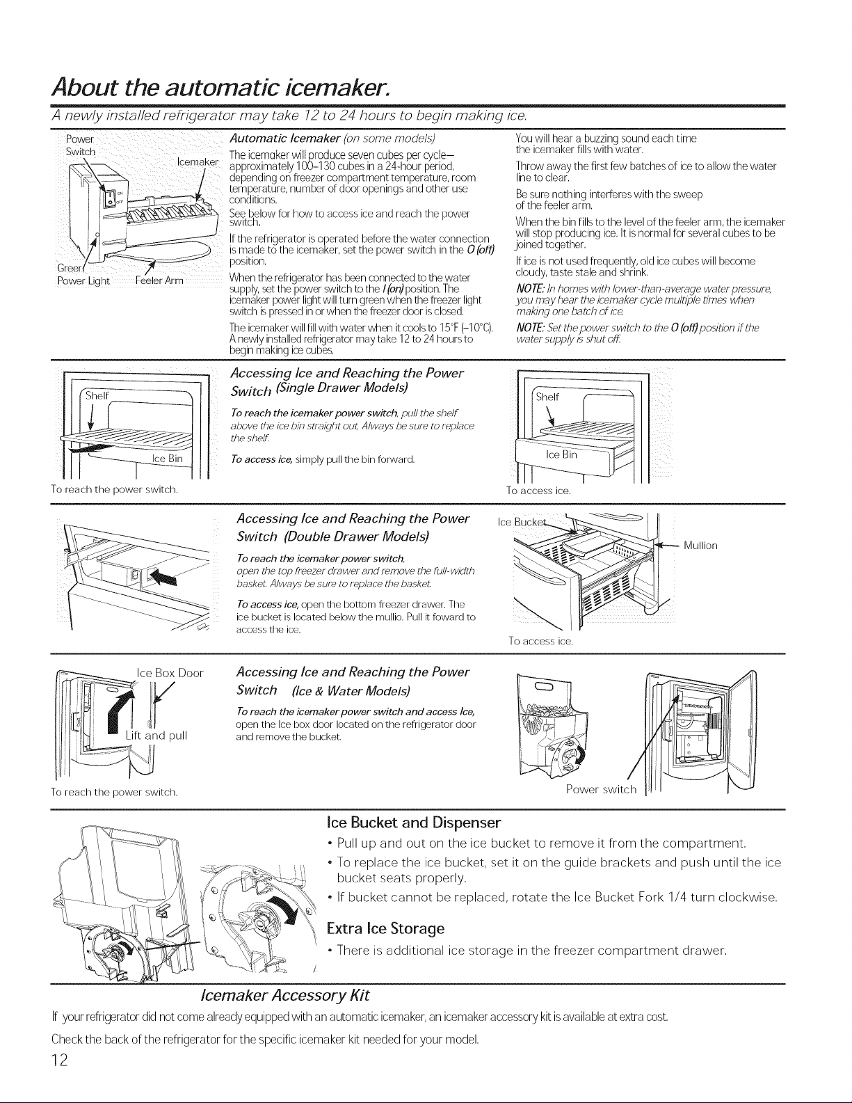
Power
Switch
\_ IcemuKer
Greer_
Power Liqnt Feeler Arm When the refrigerator has beenconnected tothe water
" supply,_t the power switch to the I(on)position, The
Automatic Icemaker (on some models)
The icemaker willproduce seven cubes per cycle-
approximately 100-130 cubes in a 24-hour period,
depending on freezer compartment temperature, room
temperature, number of door openings and other u_
conditions,
See below for how to access ice and reach the power
switch.
Ifthe refrigerator isoperated before the water connection
ismade to the icemaker, set the power switch inthe O (oft)
position,
icemaker power light will turn greenwhen the freezer light
switch ispres_d in or when the freezer door iscloud,
The icemaker will fill with water when it cools to 15°F(-10°C),
A newly installed refrigerator may take 12 to 24 hours to
begin making icecubes,
Accessing Ice and Reaching the Power
Switch (Single Drawer Models)
You will hear a buzzing sound each time
the icemaker fills with water,
Throw away the first few batches of ice to allow the water
of the feeler arm,
When the bin fills to the level of the feeler arm, the icemaker
will stop producing ice, It is normal for several cubes to be
,joinedtogether,
cloudy, taste stale and shrink,
you may hear the icemaker cyclemultiple dines when
lineto clear,
Besure nothing interferes with the sweep
Ifice is not used frequently, old ice cubes will become
NOTE:/n homes with lower-than-average water pressure,
making one batch ofice
NOTE."Setthe power switch to the 0 (oil)position if the
water supply isshut off
To reach the power switch.
Ice Box Door
Lift and pull
To reach the power switch.
To reach the icemaker power switch, pull the shelf
above the ice bin straight out, Always be sure to replf_ce
the shelf
To access ice, simply pull the bin forward.
Accessing Ice and Reaching the Power
Switch (Double Drawer Models)
Toreach the icemaker power switch,
open the top freezer drawer and remove the full-width
baske_ Always be sure to replace the baskeL
To access ice, open the bottom freezer drawer. The
ice bucket is located below the mullio. Pull it foward to
access the ice.
Accessing Ice and Reaching the Power
Switch (Ice & Water Models)
Toreach the icemaker power switch and access Ice,
open the Ice box door located on the refrigerator door
and remove the bucket.
iiii__i
ii_xl
i!i
iIi-_
To access ice.
To accessice.
Ice Bucket and Dispenser
, Pull up and out on the ice bucket to remove it from the compartment,
, To replace the ice bucket, set it on the guide brackets and push until the ice
bucket seats properly,
, If bucket cannot be replaced, rotate the Ice Bucket Fork 1/4 turn clockwise,
Extra Ice Storage
There is additional ice storage in the freezer compartment drawer,
/
Icemaker Accessory Kit
If your refrigerator did not come already equipped with an automatic icemaker, an icemaker acce,%ory kit isavailable at extra cost,
Check the back of the refrigerator for the specific icemaker kit needed for your model,
12
About the ice and water dispenser. (onsomemodels) GEAppliances.com
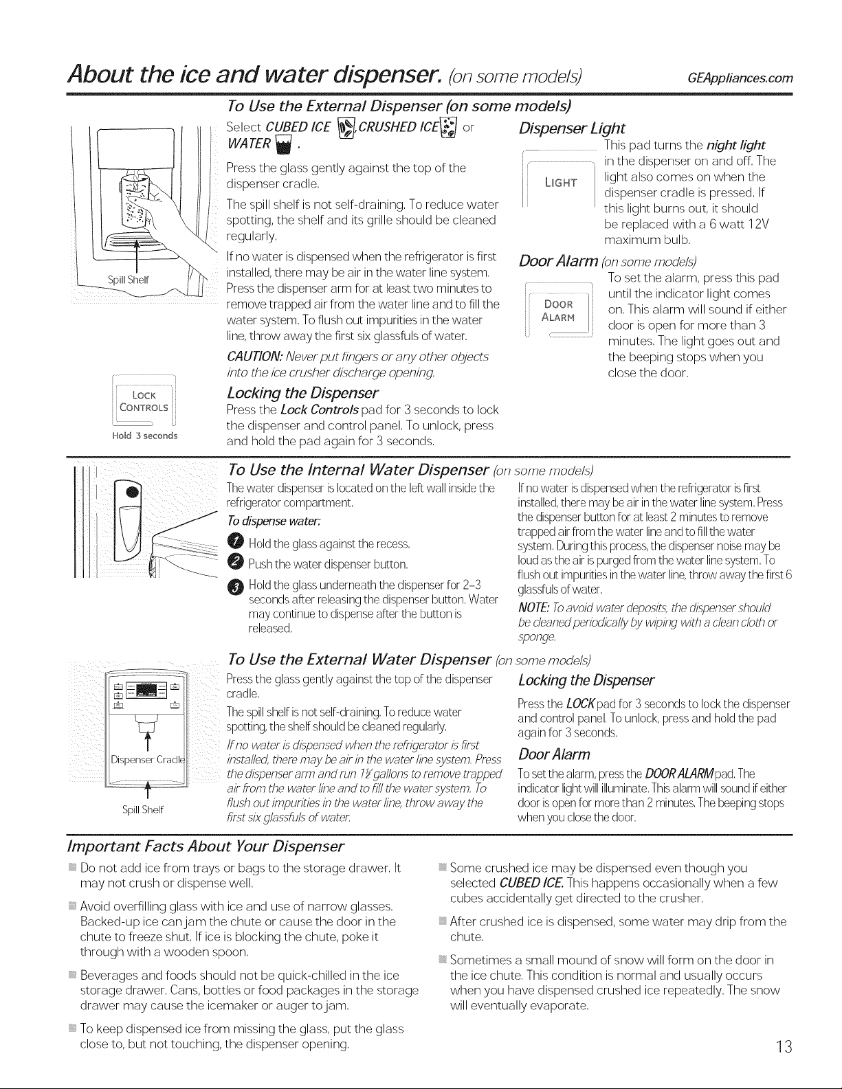
To Use the External Dispenser (on some models)
i 7
Lock
CONTROLS
Ho_d 3 secor_ds
Jt
L
i} ¸¸ il :
<_ iiiI
Dispenser Cradk
Spill Shelf
Select CUBED ICE _,CRUSHED ICE_ or
WATER
Press the glass gently against the top of the i t
dispenser cradle, L_GHT
The spill shelf is not self-draining, To reduce water
spotting, the shelf and its grille should be cleaned
regularly,
Ifno water is dispensed when the refrigerator isfirst
installed, there may be air in the water line system,
Pressthe dispenser arm for at least two minutes to
remove trapped air from the water line and to fillthe DOOR
water system, To flush out impurities in the water
line,throw away the first six glassfuls of water, ,-
CAUT/ON: Never put fingers or any other objects
into the ice crusher discharge opening,
Locking the Dispenser
Press the Lock Controls pad for 3 seconds to lock
the dispenser and control panel, To unlock, press
and hold the pad again for 3 seconds,
To Use the Internal Water Dispenser (on some mode/s)
Thewater dispenserislocated onthe left wall insidethe
refrigerator compartment,
Todispense water:
O Holdthe glassagainst the recess,
O Pushthe water dispenser button,
Holdthe glassunderneath the dispenserfor 2-3
secondsafter releasingthe dispenser button, Water
may continue to dispenseafter the button is
released,
To Use the External Water Dispenser (on
Pressthe glass gently against the top of the dispenser
cradle,
Thespillshelfisnot self-draining,Toreducewater
spotting, the shelf should becleaned regularly,
if no water isdispensed when the refrigerator Lsfirst
installed,there may beair inthe water linesystem,Press
the dLspenserarm and run lYgatlons toremove trapped
air from the water lineand to fill the water system, To
flush out impurities in the water line,throw away the
first six glassfuls of water,
Dispenser Light
i
This pad turns the night light
in the dispenser on and off, The
light also comes on when the
dispenser cradle is pressed, If
this light burns out, it should
be replaced with a 6 watt 12V
maximum bulb,
Door Alarm (onsome models)
To set the alarm, press this pad
until the indicator light comes
ALARM
Ifno water isdispensedwhen the refrigerator isfirst
installed,there maybe air inthewater linesystem,Press
the dispenserbutton forat least2minutes to remove
trapped air from the water line and to fillthe water
system,Duringthis process,the dispensernoisemay be
loud as the air ispurged from thewater linesystem,To
flushout impuritiesinthe water line,throw away the first6
glassfulsof water,
on, This alarm will sound if either
door is open for more than 3
minutes, The light goes out and
the beeping stops when you
close the door,
NOTE..Toavoid water deposits,the dispensershould
be cleanedperiodically by wiping with a cleancloth or
,sponge,
some models)
Locking the Dispenser
Pressthe LOCKpad for 3 seconds to lock the dispenser
and control panel, To unlock, press and hold the pad
again for 3seconds,
Door Alarm
Toset the alarm,pressthe DOORALARMpad,The
indicator lightwill illuminate,Thisalarmwill sound ifeither
door is openfor more than 2 minutes,Thebeepingstops
when you closethe door,
Important Facts About Your Dispenser
Do not add ice from trays or bags to the storage drawer, It
may not crush or dispense well,
, Avoid overfilling glass with ice and use of narrow glasses,
Backed-up ice can jam the chute or cause the door in the
chute to freeze shut, If ice is blocking the chute, poke it
through with a wooden spoon,
i Beverages and foods should not be quick-chilled in the ice
storage drawer, Cans, bottles or food packages in the storage
drawer may cause the icemaker or auger to jam,
i To keep dispensed ice from missing the glass, put the glass
close to, but not touching, the dispenser opening,
Some crushed ice may be dispensed even though you
selected CUBED ICE. This happens occasionally when a few
cubes accidentally get directed to the crusher,
After crushed ice is dispensed, some water may drip from the
chute,
Sometimes a small mound of snow will form on the door in
the ice chute, This condition is normal and usually occurs
when you have dispensed crushed ice repeatedly, The snow
will eventually evaporate,
13
About the ice and water dispenser. (cont)
Precise Fill (on some models)
Thiswater dispenser isequipped with afeature called Precise Fill,This
feature allows you to choose a preciseamount of water, Units include
ounces, cups, pints or liters,
Models with External Dispensers
Access By:Home > PreciseFill > SetAmount
Activate By:Using the arrow buttons to select the desired amount,
PressMOREUNITSto select between CUPS,OUNCES,PINTSor LITERS,
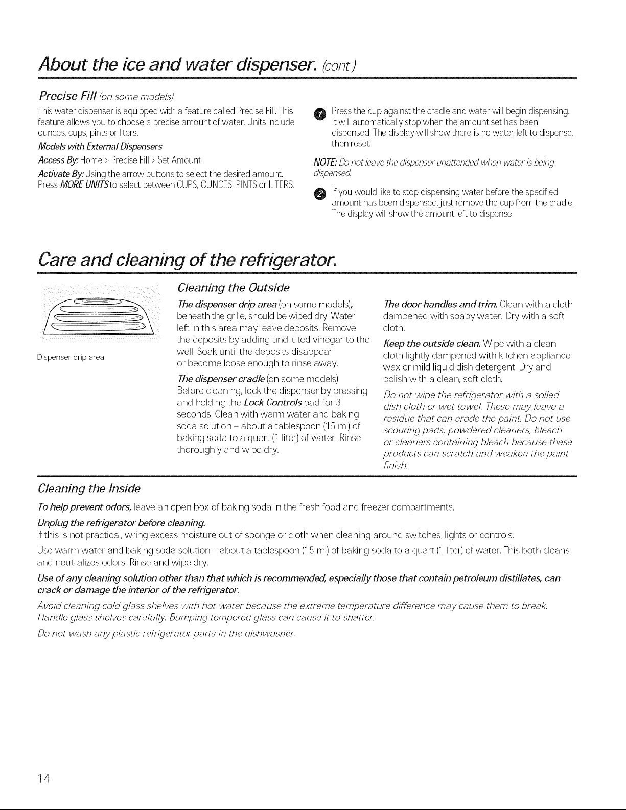
Care and cleaning of the refrigerator.
Cleaning the Outside
The dispenser drip area (on some models),
beneath the grille, should be wiped dry, Water
left in this area may leave deposits, Remove
the deposits by adding undiluted vinegar to the
Dispenser drip area
well, Soak until the deposits disappear
or become loose enough to rinse away,
The dispenser cradle (on some models),
Before cleaning, lock the dispenser by pressing
and holding the Lock Controls pad for 3
seconds, Clean with warm water and baking
soda solution - about a tablespoon (15 ml) of
baking soda to a quart (1 liter) of water, Rinse
thoroughly and wipe dry,
Pressthe cup against the cradle and water will begindispensing,
0
Itwill automatically stop when the amount set hasbeen
dispensed,The display will show there is no water leftto dispense,
then reset,
NOTE."Do not leave the dispenserunattended when water Lsbeing
dLspensed
0 Ifyou would liketo stop dispensingwater before the specified
amount has been dispensed,just remove the cup from the cradle,
The displaywill show the amount left to dispense,
The door handles and trim. Clean with a cloth
dampened with soapy water, Dry with a soft
cloth,
Keep the outside clean. Wipe with a clean
cloth lightly dampened with kitchen appliance
wax or mild liquid dish detergent, Dry and
polish with a clean, soft cloth,
Do not wipe the refi'igerator with a soiled
dish cloth or wet towel, These may leave a
residue that can erode the paint, Do not use
scouring pads, powdered cleaners, bleach
or cleaners containing bleach because these
products can scratch and weaken the paint
finish,
Cleaning the Inside
Tohelp prevent odors, leave an open box of baking soda in the fresh food and freezer compartments,
Unplug the refrigerator before cleaning.
If this is not practical, wring excess moisture out of sponge or cloth when cleaning around switches, lights or controls,
Use warm water and baking soda solution - about a tablespoon (15 ml) of baking soda to a quart (1 liter) of water, This both cleans
and neutralizes odors, Rinse and wipe dry,
Use of any cleaning solution other than that which is recommended, especially those that contain petroleum distillates, can
crack or damage the interior of the refrigerator.
Avoid cleaning cold glass shelves with hot water because the extreme temperature diffhrence may cause them to break,
Handle glass shelves careful_, Bumping tempered glass can cause it to shatter,
Do not wash any plastic refHgerator parts in the dishwasher,
14
Replacing the light bulbs. GEApplia.ces.com
Turning the contro/ to the 0 (off) position does not remove power to the light circuit.
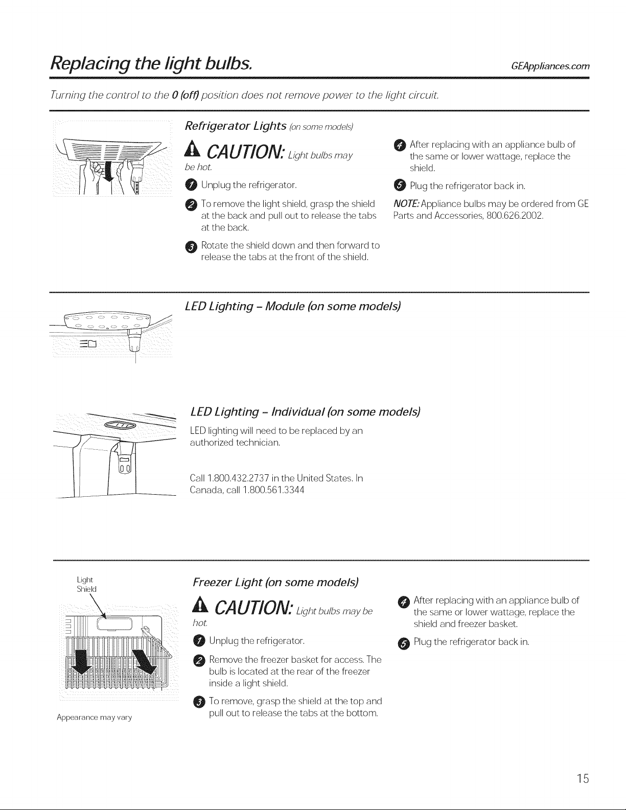
Refrigerator Lights (onsomemodd.s)
CAUTION:L/g. b.,bs
be hot,
After replacing with an appliance bulb of
the same or lower wattage, replace the
shield.
O Unplug the refrigerator.
To remove the light shield, grasp the shield
at the back and pull out to release the tabs
at the back.
Rotate the shield down and then forward to
release the tabs at the front of the shield.
LED Lighting - Module (on some models)
LED Lighting - Individual (on some models)
LED lighting will need to be replaced by an
authorized technician.
Call 1.800.432.2737 in the United States. In
Canada, call 1.800.561.3344
Plug the refrigerator back in.
NOTE'Appliance bulbs may be ordered from GE
Parts and Accessories, 800.626.2002.
Light
Shield
Appearance may vary
Freezer Light (on some models)
A CAUTION:L g , b./bs
hot.
Unplug the refrigerator.
Remove the freezer basket for access. The
bulb is located at the rear of the freezer
inside a light shield.
To remove, grasp the shield at the top and
pull out to release the tabs at the bottom.
After replacing with an appliance bulb of
the same or lower wattage, replace the
shield and freezer basket.
Plug the refrigerator back in.
15
Trim kits and decorator panels.
For panel-required models
Read these instructions completely and carefully.
Before YouBegin
Some models are equipped with trim kits that allow you to install door panels. You can order pre-cut
black or white decorator panels from GE Parts and Accessories, 800.626.2002, or you can add wood
panels to match your kitchen cabinets.
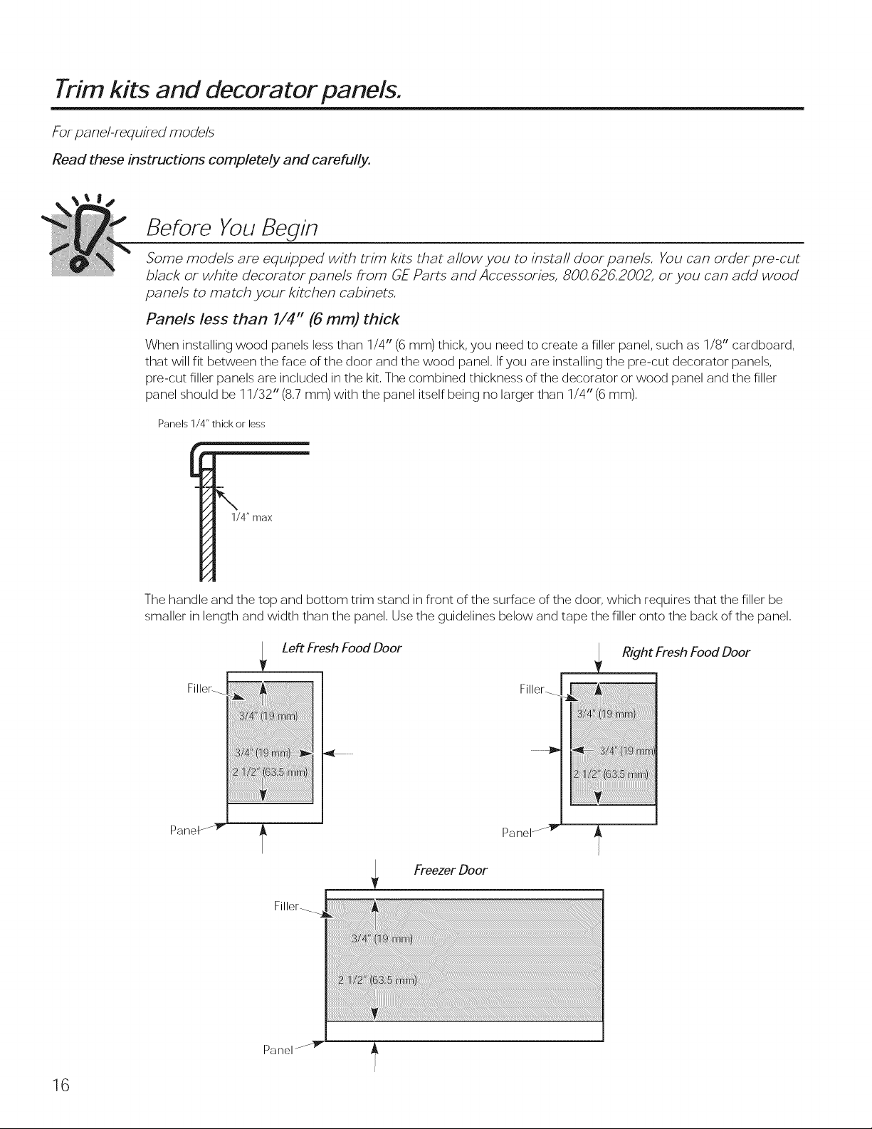
Panels less than 1/4" (6 ram) thick
When installing wood panels less than 1/4" (6 ram) thick, you need to create a filler panel, such as 1/8" cardboard,
that will fit between the face of the door and the wood panel, Ifyou are installing the pre-cut decorator panels,
pre-cut filler panels are included in the kit, The combined thickness of the decorator or wood panel and the filler
panel should be 11/32" (8,7 mm) with the panel itself being no larger than 1/4" (6 mm),
Panels 1/4" thick or less
1/4" max
The handle and the top and bottom trim stand in front of the surface of the door, which requires that the filler be
smaller in length and width than the panel, Use the guidelines below and tape the filler onto the back of the panel,
Panel
Filler-
Left Fresh Food Door
Filler_
Paneb
Freezer Door
Filler_
Right Fresh Food Door
16
Panel-
Trim kits and decorator panels. GEApp ancescom
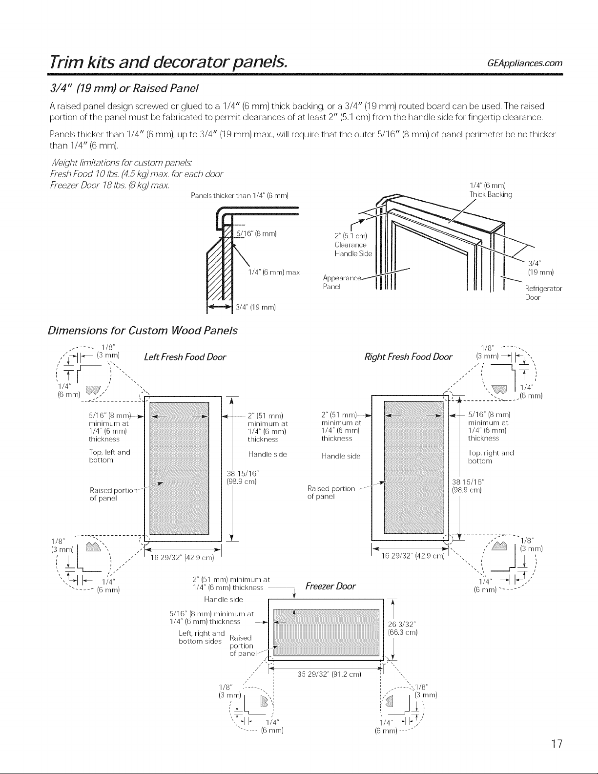
3/4" (19 mm) or Raised Panel
A raised panel design screwed or glued to a 1/4" (6 mm) thick backing, or a 3/4" (19 mm) routed board can be used, The raised
portion of the panel must be fabricated to permit clearances of at least 2" (5,1 cm) from the handle side for fingertip clearance,
Panels thicker than 1/4" (6mm), up to 3/4" (19 mm) max,, will require that the outer 5/16" (8 mm) of panel perimeter be no thicker
than 1/4" (6 mm),
Weight limitations for custom panels:'
FreshFood 10Ibs,(4,5kg)max, for each door
Freezer Door 78 Ibs, (8 kg) max,
Panels thicker than 1/4" (6 mm)
_. 7_Thick Backing
1/4" (6 mm)
Dimensions for Custom Wood Panels
. .... - 1/8"
1/4"
(6mm)_'"
____'2.......... 2
5/1 6" (8 mm)
minimum at
1/4" (6 mm)
thickness
Top, left and
bottom
Raised
of panel
Left Fresh Food Door
€
6" (8 mm)
1/4" (6 mm) max
3/4" (19 mm)
..........2" (51 mm)
minimum at
1/4" (6 mm)
thickness
Handle side
3_ 15/16"
(98.9 cm)
2" (5.1 cm)
Clearance
Handle Side
Panel
2"(51
minimum at
1/4" (6 mm)
thickness
Handle side
Raised portion
of panel
Right Fresh Food Door
[[[[ I Refrigerator
Door
1/8 ...... -.
(;smm/_'1I__",,
t _-',
|
1/4"
.(6 mm)
5/16" (8 mm)
minimum at
1/4" (6 mm)
thickness
Top, right and
bottom
38 15/16"
(98.9 cm)
16 29/32" (42.9 cm)
2" (51 mm) minimum at
1/4" (6 mm) thickness
Handle side
5/16" (8 mm) minimum at
1/4" (6 mm)thickness
Left, right and .
bottom sides Raised
pomon
of panel "i
_"_ 3529/32"(91,2cm) '"_l-
1/8"/]--
(3 mm) "" "
...... (6 mm)
Freezer Door
3/32
! ,[._(66.3 cm)
l
i ........ ",.,1/8"
/ (3mm)
1/4" _1 _'"
(6 mm) .....
"_ .... -1/8"
1/4"
(6 rnrn) ......
17
Installation
efrigerator
Instructions
Questions? Call 800.GE.CARES (800.432.2737) or visit our Website at: GEAppliances.com
In Canada, call 1.800.561.3344 or visit our Website at: www.GEAppliances.ca
BEFORE YOU BEGIN
Read these instructions completely and carefully.
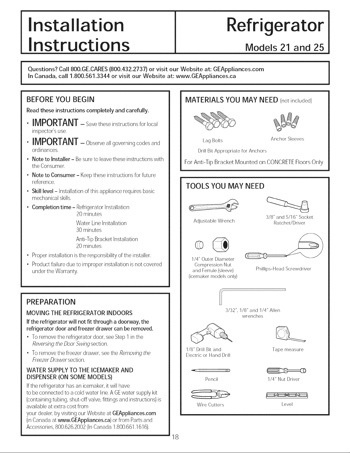
MATERIALSYOU MAY NEED (notincluded)
Models 21 and 25
• IMPORTANT- Savetheseinstructionsforlocal
inspector's use,
• IMPORTANT- Observea,governingcodesand
ordinances,
• Note to Installer - Besureto leavethese instructions with
the Consumer,
• Note to Consumer- Keepthese instructions for future
reference,
• Skill level- Installationof this appliance requires basic
mechanical skills,
• Completion time- RefrigeratorInstallation
20 minutes
Water Line Installation
30 minutes
For Anti-Tip Bracket Mounted on CONCRETEFloors Only
LagBolts
DrillBitAppropriate for Anchors
TOOLS YOU MAY NEED
Adjustable Wrench
Anchor Sleeves
3/8" and 5/16" Socket
Ratchet/Driver
Anti-Tip Bracket Installation
20 minutes
• Proper installation isthe responsibilityof the installer,
• Product failure dueto improper installation isnot covered
under the Warranty,
PREPARATION
MOVING THE REFRIGERATOR INDOORS
If the refrigerator will not fit through a doorway, the
refrigerator door and freezer drawer can be removed.
• To remove the refrigerator door, seeStep 1 inthe
Reversingthe Door Swing section,
• To remove the freezerdrawer, seethe Removingthe
FreezerDrawer section,
WATER SUPPLY TO THE ICEMAKER AND
DISPENSER (ON SOME MODELS)
Ifthe refrigerator has an icemaker, it will have
to beconnected to a cold water line,A GEwater supplykit
(containing tubing, shut-off valve,fittings and instructions)is
available at extra costfrom
your dealer,by visitingour Website at GEAppliances.com
(inCanada at _ww.GEAppliances.ca) or from Parts and
Accessories,800,626,2002(InCanada 1,800,661,1616),
1/4" Outer Diameter
Compression Nut
and Ferrule (sleeve)
(icemaker models only)
1/8" Drill Bit and
Electric or Hand Drill
18
Phillips-Head Screwdriver
3/32", 1/8" and 1/4" Allen
wrenches
Tape measure
Pencil 1/4" NutDriver
Wire Cutters
Level
Installation Instructions
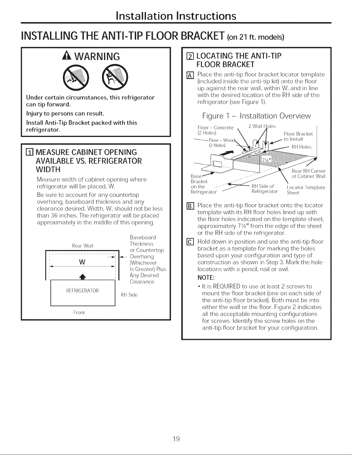
INSTALLINGTHEANTI-TIP FLOOR BRACKET(on21ft.models)
WARNING
Under certain circumstances, this refrigerator
can tip forward.
Injury to persons can result.
Install Anti-Tip Bracket packed with this
refrigerator.
[] MEASURECABINET OPENING
AVAILABLE VS. REFRIGERATOR
WIDTH
Measure width of cabinet opening where
refrigerator will be placed, W.
Be sure to account for any countertop
overhang, baseboard thickness and any
clearance desired. Width, W, should not be less
than 36 inches. The refrigerator will be placed
approximately in the middle of this opening.
Baseboard
Rear Wall
W
REFRIOERATOR
Front
41 _ Overhang
,_i (Whichever
Thickness
Is Greater) Plus
or Countertop
Any Desired
Clearance
RHSide
LOCATING THE ANTI-TIP
[]
FLOOR BRACKET
Place the anti-tip floor bracket Iocator template
%
(included inside the anti-tip kit) onto the floor
up against the rear wall, within W, and in line
with the desired location of the RH side of the
refrigerator (see Figure 1).
Figure 1 - Installation Overview
Refrigerator _ Refrigerator Sheet
Place the anti-tip floor bracket onto the Iocator
m
template with its RH floor holes lined up with
the floor holes indicated on the template sheet,
approximately 71/4" from the edge of the sheet
or the RH side of the refrigerator.
F1
Hold down in position and use the anti-tip floor
bracket as a template for marking the holes
based upon your configuration and type of
construction as shown in Step 3. Mark the hole
locations with a pencil, nail or awl.
NOTE:
• It is REQUIREDto use at least 2 screws to
mount the floor bracket (one on each side of
the anti-tip floor bracket). Both must be into
either the wall or the floor. Figure 2 indicates
all the acceptable mounting configurations
for screws. Identify the screw holes on the
anti-tip floor bracket for your configuration.
19
Installation Instructions
INSTALLINGTHEANTI-TIP FLOOR BRACKET(on21ft.models)(Cont.)
I_l LOCATING THE ANTI-TIP
FLOOR BRACKET(cont.)
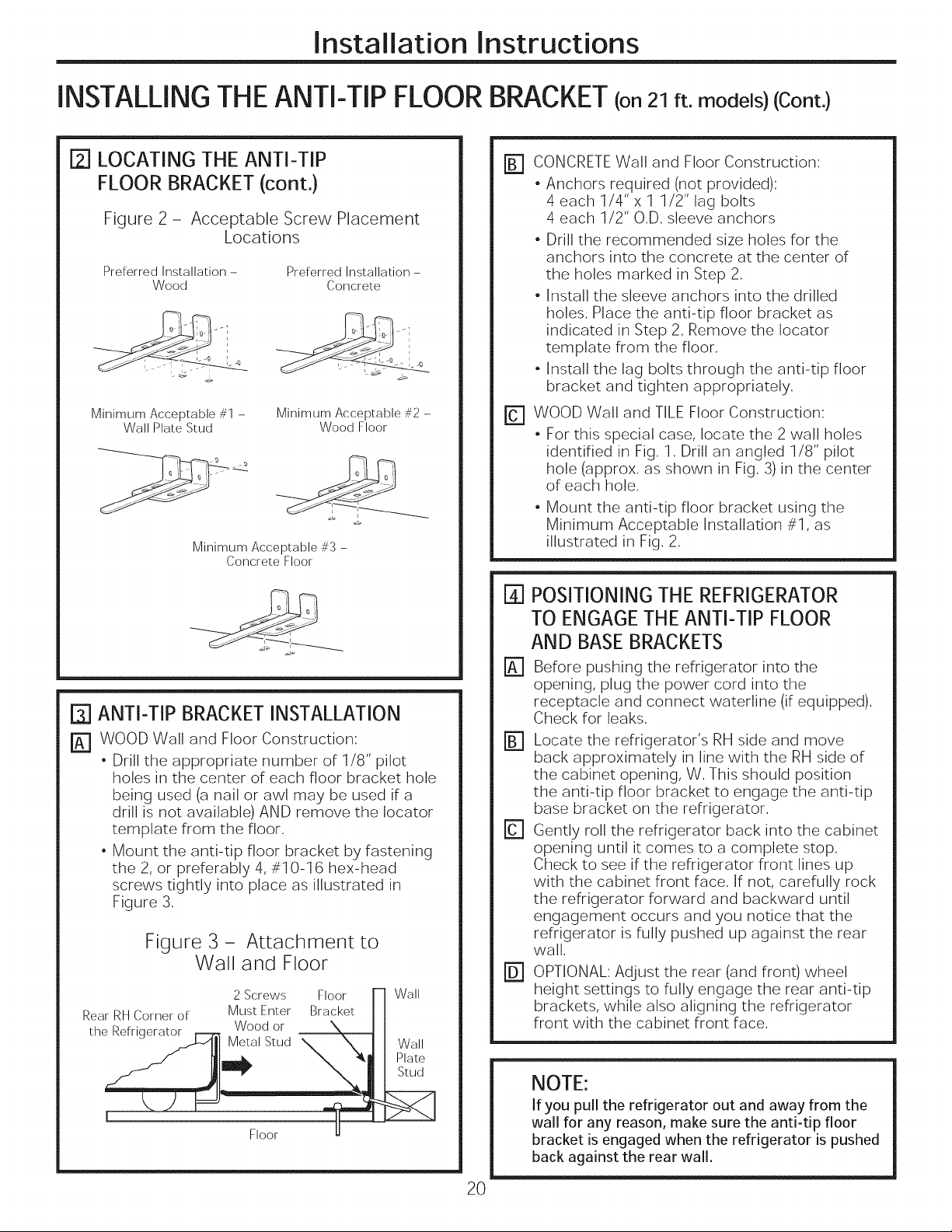
Figure 2 - Acceptable Screw Placement
Locations
Preferred Installation-
Wood
Minimum Acceptable #1 -
Wall Plate Stud
Minimum Acceptable #3 -
Concrete Floor
Preferred Installation-
Concrete
Minimum Acceptable #2 -
Wood Floor
[] ANTI-TIP BRACKETINSTALLATION
_] WOOD Wall and Floor Construction:
• Drill the appropriate number of 1/8" pilot
holes in the center of each floor bracket hole
being used (a nail or awl may be used if a
drill is not available) AND remove the Iocator
template from the floor.
• Mount the anti-tip floor bracket by fastening
the 2, or preferably 4, #10-1 6 hex-head
screws tightly into place as illustrated in
Figure 3.
Figure 3 - Attachment to
Wall and Floor
2 Screws Floor
Rear RHCorner of
the Refrigerator
Must Enter Bracket
Wood or
Floor
Wall
Wall
Plate
Stud
[] CONCRETEWall and Floor Construction:
• Anchors required (not provided):
4 each 1/4"x 1 1/2" lag bolts
4 each 1/2" O.D. sleeve anchors
• Drill the recommended size holes for the
anchors into the concrete at the center of
the holes marked in Step 2.
• Install the sleeve anchors into the drilled
holes. Place the anti-tip floor bracket as
indicated in Step 2. Remove the Iocator
template from the floor.
• Install the lag bolts through the anti-tip floor
bracket and tighten appropriately.
r_ WOOD Wall and TILE Floor Construction:
• For this special case, locate the 2 wall holes
identified in Fig. 1. Drill an angled 1/8" pilot
hole (approx. as shown in Fig. 3)in the center
of each hole.
• Mount the anti-tip floor bracket using the
Minimum Acceptable Installation #1, as
illustrated in Fig. 2.
%
POSITIONINGTHE REFRIGERATOR
TO ENGAGETHE ANTI-TIP FLOOR
AND BASEBRACKETS
%
Before pushing the refrigerator into the
opening, plug the power cord into the
receptacle and connect waterline (if equipped).
Check for leaks.
Locate the refrigerator's RH side and move
back approximately in line with the RH side of
the cabinet opening, W. This should position
the anti-tip floor bracket to engage the anti-tip
base bracket on the refrigerator.
Gently roll the refrigerator back into the cabinet
opening until it comes to a complete stop.
Check to see if the refrigerator front lines up
with the cabinet front face. If not, carefully rock
the refrigerator forward and backward until
engagement occurs and you notice that the
refrigerator is fully pushed up against the rear
wall.
OPTIONAL: Adjust the rear (and front) wheel
@
height settings to fully engage the rear anti-tip
brackets, while also aligning the refrigerator
front with the cabinet front face.
NOTE:
If you pull the refrigerator out and away from the
wall for any reason, make sure the anti-tip floor
bracket is engaged when the refrigerator is pushed
back against the rear wall.
2O
Installation Instructions
INSTALLING THE REFRIGERATOR
REFRIGERATOR LOCATION
• Do not install the refrigerator where the temperature will
go below 60°F(16°C)becauseitwill not run often enough
to maintain proper temperatures,
• Do not install the refrigerator where the temperature will
go above 100°F(37°0)because it will not perform properly,
• Install iton afloor strong enough to support it fully loaded,
CLEARANCES
Allowthe following clearances for easeof installation, proper
air circulation and plumbing and electrical connections,
Standard Depth Counter Depth
Models Models
Sides 1/8" (3mm) 1/8" (3mm)
Top 1" (25mm) 1" (25mm)
Back 2" (50mm) 2" (50mm)
REMOVETOPCAP(onsome models)
• IMPORTANTNOTE:This refrigerator is34-I/2" deep.
Doors and passageways leading to the installation
location must be at least 36" wide in order to leavethe
doors and handles attached to the refrigerator while
transporting it into the installation location. If
passageways are lessthan 36", the refrigerator doors
and handles can easily be scratched and damaged.
Thetop cap and doors can be removed to allow the
refrigerator to be safely moved indoors. Start with Step A.
• If it is not necessary to remove doors, skip StepA. Leave
tape and all packaging on doors until the refrigerator is
in the final location.
• SKIDREMOVAL:Tilt refrigerator to each side to remove
skid.
• NOTE:Usea padded hand truck to move this refrigerator.
Placethe refrigerator on the hand truck with a side
against the truck. We strongly recommend that TWO
PEOPLEmove and complete this installation.
[_ Locateand remove the two Phillipshead screwson the
top of the refrigerator, Removethe two screws on each
sideat the rear of the top cap,
Liftoff and remove top cap,
FB] Removethe fresh-food door,Referto Steps1 through 3
of "Reversingthe DoorSwing"section,
r_ Removethe bottom freezer drawer, Referto "Removing
FreezerDrawer"section,
rD-1 Moverefrigerator to the installation location,
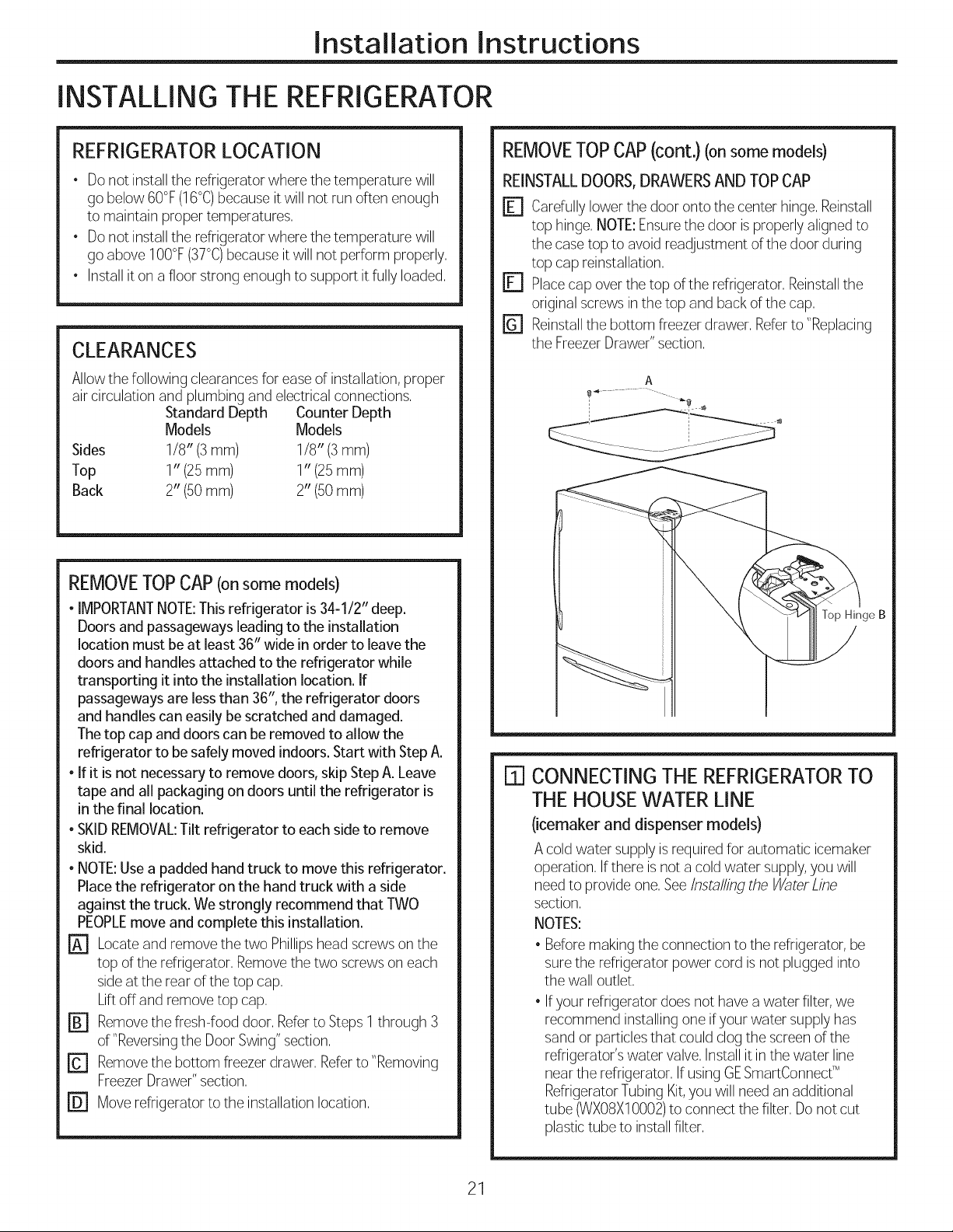
REMOVETOPCAP(cont.) (onsome models)
REINSTALLDOORS,DRAWERSANDTOPCAP
r_ Carefullylower the door onto the center hinge, Reinstall
top hinge,NOTE:Ensurethe door is properlyaligned to
the casetop to avoid readjustment of the door during
top cap reinstallation,
[] Placecap over the top of the refrigerator, Reinstallthe
original screws inthe top and back of the cap,
r_ Reinstallthe bottom freezerdrawer, Referto "Replacing
the FreezerDrawer"section,
A
Top Hinge B
[] CONNECTING THE REFRIGERATORTO
THE HOUSEWATER LINE
(icemaker and dispenser models)
A cold water supply is required for automatic icemaker
operation, Ifthere is not a cold water supply,you will
need to provide one, See/nstalling the _ater Line
section,
NOTES:
• Beforemaking the connection to the refrigerator, be
surethe refrigerator power cord isnot plugged into
the wall outlet,
Ifyour refrigerator does not have a water filter,we
recommend installing one ifyour water supply has
sand orparticlesthat could clog the screen of the
refrigerator'swater valve,Install it in the water line
near the refrigerator, If usingGESmartConnecfM
RefrigeratorTubing Kit,you will need an additional
tube (WXOSX10002)toconnect the filter, Donot cut
plastictube to install filter,
21
Installation Instructions
INSTALLING THE REFRIGERATOR(cont.}
I_1 CONNECTING THE REFRIGERATOR TO
THE HOUSE WATER LINE (cont.)
[_] If you are using copper tubing, place a
compression nut and ferrule (sleeve) onto the
end of the tubing coming from the house cold
water supply.
If you are using the GE SmartConnect"
tubing, the nuts are already assembled to
the tubing.
rBI If you are using copper tubing, insert
the end of the tubing into the refrigerator
connection, at the back of the refrigerator,
as far as possible. While holding the tubing,
tighten the fitting.
If you are using GE SmartConnect " tubing,
insert the molded end of the tubing into the
refrigerator connection, at the back of the
refrigerator, and tighten the compression nut
until it is hand tight. Then tighten one additional
turn with a wrench. Overtightening may cause
leaks.
r_ Fasten the tubing into the clamp provided to
hold it in position. You may need to pry open
the clamp.
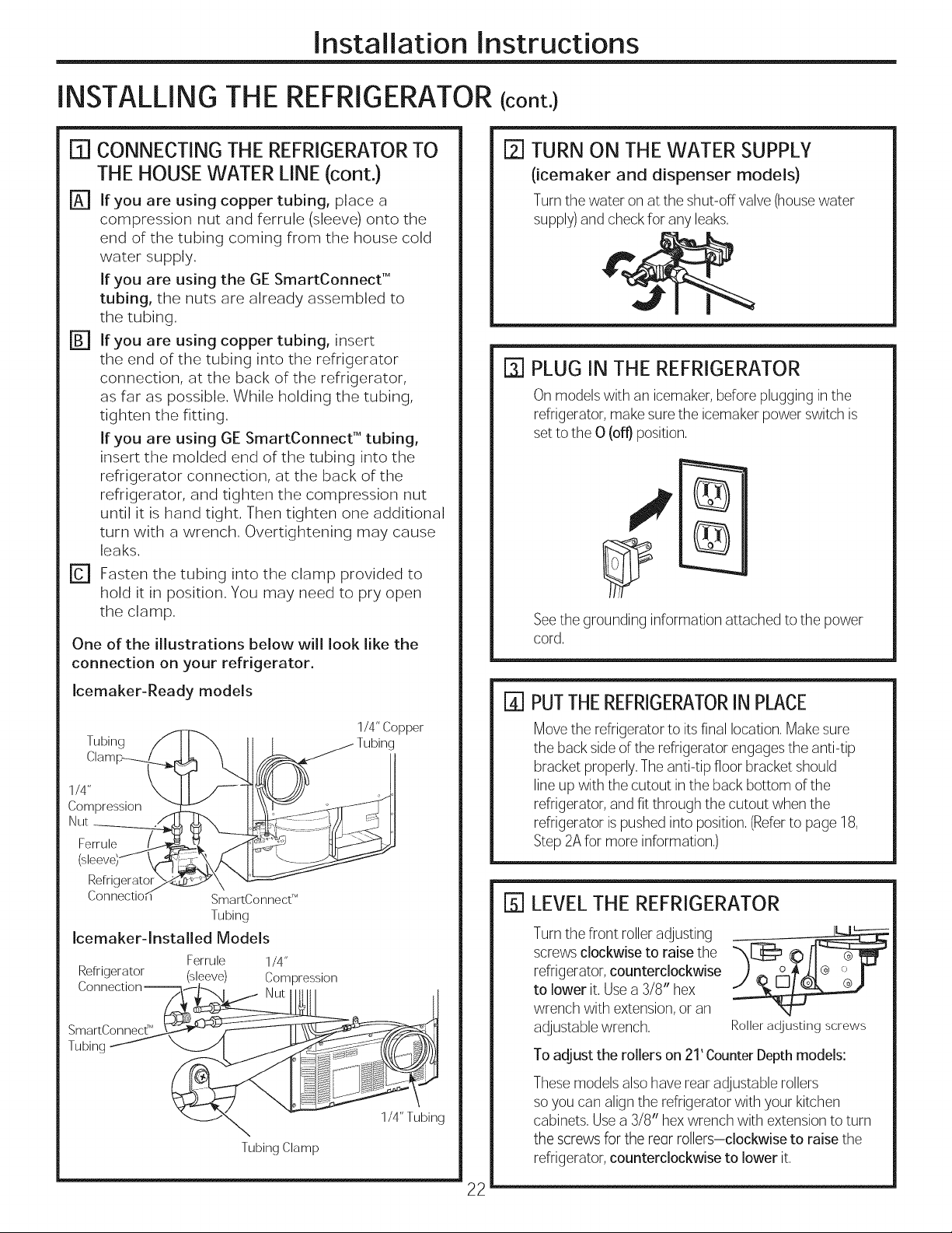
One of the illustrations below will look like the
connection on your refrigerator.
[] TURN ON THEWATER SUPPLY
(icemaker and dispenser models}
Turnthe water on at the shut-off valve (housewater
supply)and check for any leaks,
F3--]PLUG IN THE REFRIGERATOR
On models with an icemaker, beforeplugging in the
refrigerator, makesure the icemaker power switch is
set to the 0 (off} position,
Seethe grounding information attached to the power
cord.
Icemaker-Ready models
Tubing f
Clamp_
1/4"
Compression
(sbeveS _
Refrigerator .%4
Connectio,_
Icemaker-lnstalled Models
Refrigerator (sleeve) Compression
SmartConnecf M
Tubing
f
SmartConnect TM
Tubing
Ferrule 1/4"
Nut
Tubing Clamp
1/4"Copper
1/4" Tubing
I_1PUTTHEREFRIGERATORINPLACE
Move the refrigerator to itsfinal location.Make sure
the backside of the refrigerator engagesthe anti-tip
bracket properly.Theanti-tip floor bracket should
line up with the cutout in the back bottom of the
refrigerator, andfit through the cutout when the
refrigerator is pushedinto position.(Referto page 18,
Step2Afor more information.)
[] LEVELTHE REFRIGERATOR
Turnthe front rolleradjusting
screws clockwise to raise the
refrigerator, counterclockwise
to lower it, Usea 3/8" hex
wrench with extension,or an
adjustable wrench,
Toadjust the rollers on 21' CounterDepthmodels:
Thesemodels also have rear adjustable rollers
soyou can align the refrigerator with your kitchen
cabinets, Usea 3/8" hexwrench with extension to turn
the screwsfor the rear rollers-clockwise to raise the
refrigerator, counterclockwise to lower it,
Roller adjusting screws
22
Installation Instructions
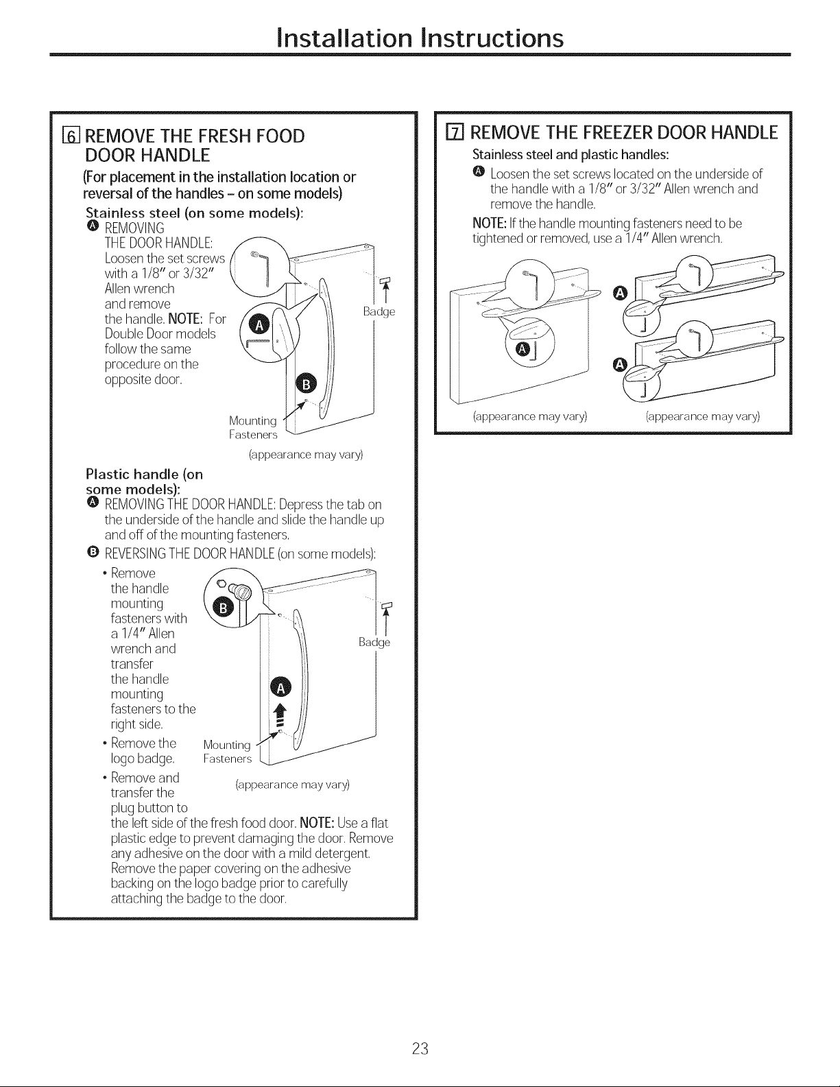
I-_ REMOVETHE FRESHFOOD
DOOR HANDLE
(For placement in the installation location or
reversal of the handles - on some models)
Stainless steel (on some models):
@ REMOVING
THEDOORHANDLE:
Loosenthe set screws
with a 1/8" or 3/32"
Allenwrench
and remove
the handle, NOTE:For
DoubleDoor models
follow the same
procedure onthe
opposite door,
Mounting
Fasteners
(appearance may vary)
Plastic handle (on
some models):
@ REMOVINGTHEDOORHANDLE:Depressthe tab on
the undersideof the handle and slidethe handle up
and off of the mounting fasteners,
Q REVERSINGTHEDOORHANDLE(on some models):
J
I_1 REMOVE THE FREEZER DOOR HANDLE
Stainless steel and plastic handles:
O Loosenthe set screwslocated on the underside of
the handle with a 1/8" or 3/32" Allen wrench and
remove the handle,
NOTE:Ifthe handlemounting fastenersneedto be
tightened or removed,use a 1/4" Allenwrench,
Badge
(appearance may vary) (appearance may vary)
the handle
mounting
• Remove
fasteners with
a 1/4" Allen
wrench and
transfer
the handle
mounting
fasteners to the
right side,
• Removethe Mounting
logo badge, Fasteners
• Removeand
transfer the
plug button to
the left side of the fresh food door, NOTE:Usea flat
plasticedge to prevent damaging the door, Remove
any adhesiveon the door with a mild detergent,
Removethe paper coveringon the adhesive
backing on the logo badge prior to carefully
attaching the badge to the door,
(appearance may vary)
23
Installation Instructions
INSTALLING THE REFRIGERATOR(cont,)
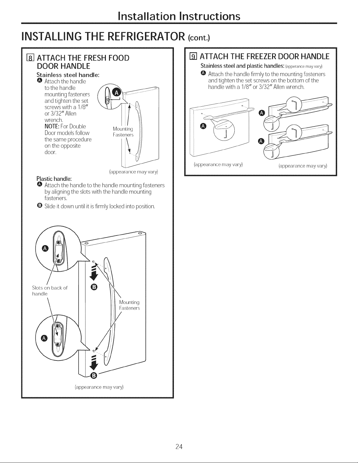
rs-iATTACH THE FRESHFOOD
DOOR HANDLE
Stainless steel handle:
@ Attach the handle
to the handle
mounting fasteners
and tighten the set
screws with a 1/8"
or 3/32" Allen
wrench,
NOTE:For Double
Doormodels follow
the same procedure
on the opposite
door,
Plastic handle:
@ Attach the handle to the handle mounting fasteners
by aligningthe slotswith the handle mounting
fasteners,
Q Slideit down until it isfirmly locked into position,
Mounting
Fasteners
(appearance may vary)
[] ATTACH THE FREEZERDOOR HANDLE
Stainless steel and plastic handles: (apperancemay vary)
@ Attach the handle firmly to the mounting fasteners
and tighten the set screws onthe bottom of the
handle with a 1/8" or 3/32" Allenwrench,
(appearance may vary)
(appearance may vary)
Slots on back of
handle
(appearance may vary)
24
Installation Instructions
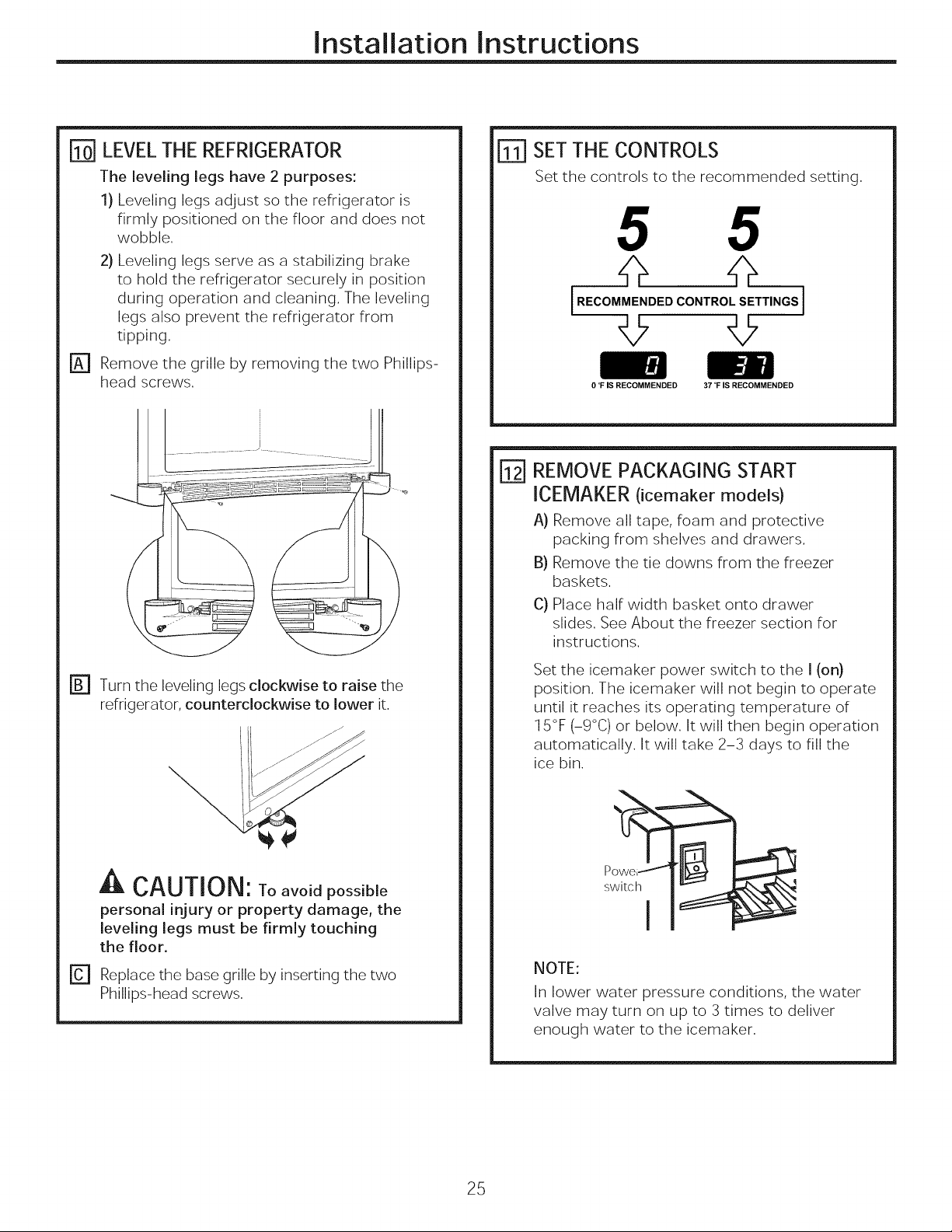
LEVELTHE REFRIGERATOR
The leveling legs have 2 purposes:
1) Leveling legs adjust so the refrigerator is
firmly positioned on the floor and does not
wobble.
2) Leveling legs serve as a stabilizing brake
to hold the refrigerator securely in position
during operation and cleaning. The leveling
legs also prevent the refrigerator from
tipping.
[_ Remove the grille by removing the two Phillips-
head screws.
SET THE CONTROLS
Set the controls to the recommended setting.
5 5
IREco.OCO"TRO'SETT'"OS]
© tt
0 °F IS RECOMMENDED 37 °F IS RECOMMENDED
REMOVEPACKAGING START
ICEMAKER (icemaker models)
A) Remove all tape, foam and protective
packing from shelves and drawers.
B) Remove the tie downs from the freezer
baskets.
C) Place half width basket onto drawer
slides. See About the freezer section for
instructions.
FB1 Turn the leveling legs clockwise to raise the
refrigerator, counterclockwise to lower it.
A CAUTION: Toavoidpossible
personal injury or property damage, the
leveling legs must be firmly touching
the floor.
[] Replace the base grille by inserting the two
Phillips-head screws.
Set the icemaker power switch to the I (on)
position. The icemaker will not begin to operate
until it reaches its operating temperature of
15°F (-9°C) or below. It will then begin operation
automatically. It will take 2-3 days to fill the
ice bin.
NOTE:
In lower water pressure conditions, the water
valve may turn on up to 3 times to deliver
enough water to the icemaker.
25
Installation Instructions
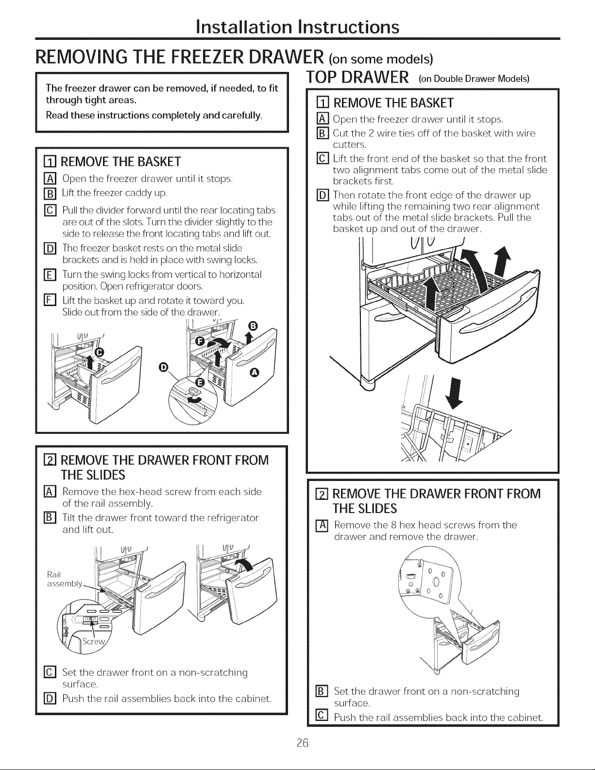
REMOVING
The freezer drawer can be removed, if needed, to fit
through tight areas.
Read these instructions completely and carefully.
THE FREEZERDRAWER (onsome models)
[]] REMOVE THE BASKET
r_ Open the freezer drawer until it stops.
r_ Lift the freezer caddy up,
rc] Pull the divider forward until the rear locating tabs
are out of the slots, Turn the divider slightly to the
side to release the front locating tabs and lift out,
FD] The freezer basket rests on the metal slide
brackets and is held in place with swing locks.
r_ Turn the swing locks from vertical to horizontal
position, Open refrigerator doors,
r_ Lift the basket up and rotate it toward you,
Slide out from the side of the drawer,
TOPDRAWER (on Double Drawer Models)
[][] REMOVE THE BASKET
Open the freezer drawer until it stops.
r_ cut the 2 wire ties off of the basket with wire
cutters.
r_ Lift the front end of the basket so that the front
two alignment tabs come out of the metal slide
brackets first,
r_ Then rotate the front edge of the drawer up
while lifting the remaining two rear alignment
tabs out of the metal slide brackets, Pull the
basket up and out of the drawer,
V
[2] REMOVE THE DRAWER FRONT FROM
THE SLIDES
[] Remove the hex-head screw from each side
of the rail assembly,
[] Tilt the drawer front toward the refrigerator
and lift out.
Rail
assembl
\
[] Set the drawer front on a non-scratching
surface,
r_ Push the rail assemblies back into the cabinet.
[2] REMOVE THE DRAWER FRONT FROM
THE SLIDES
rA] Remove the 8 hex head screws from the
drawer and remove the drawer.
[] Set the drawer front on a non-scratching
surface,
r_ Push the rail assemblies back into the cabinet.
26
Installation Instructions
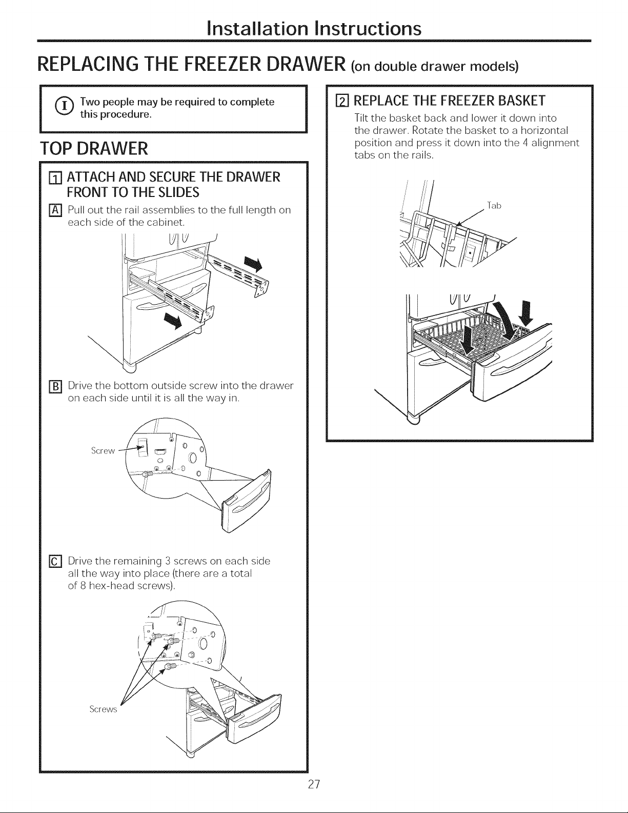
REPLACING THE FREEZERDRAWER (on double drawer models)
(_Two people may be required to complete
this procedure.
TOP DRAWER
[]] ATTACHAND SECURETHE DRAWER
FRONT TO THE SLIDES
[] Pull out the rail assemblies to the full length on
each side of the cabinet.
r_ Drive the bottom outside screw into the drawer
on each side until it is all the way in.
[}1 REPLACE THE FREEZER BASKET
Tilt the basket back and lower it down into
the drawer. Rotate the basket to a horizontal
position and press it down into the 4 alignment
tabs on the rails.
Tab
Screw
r_ Drive the remaining 3 screws on each side
all the way into place (there are a total
of 8 hex-head screws).
\
Screws
27
Installation Instructions
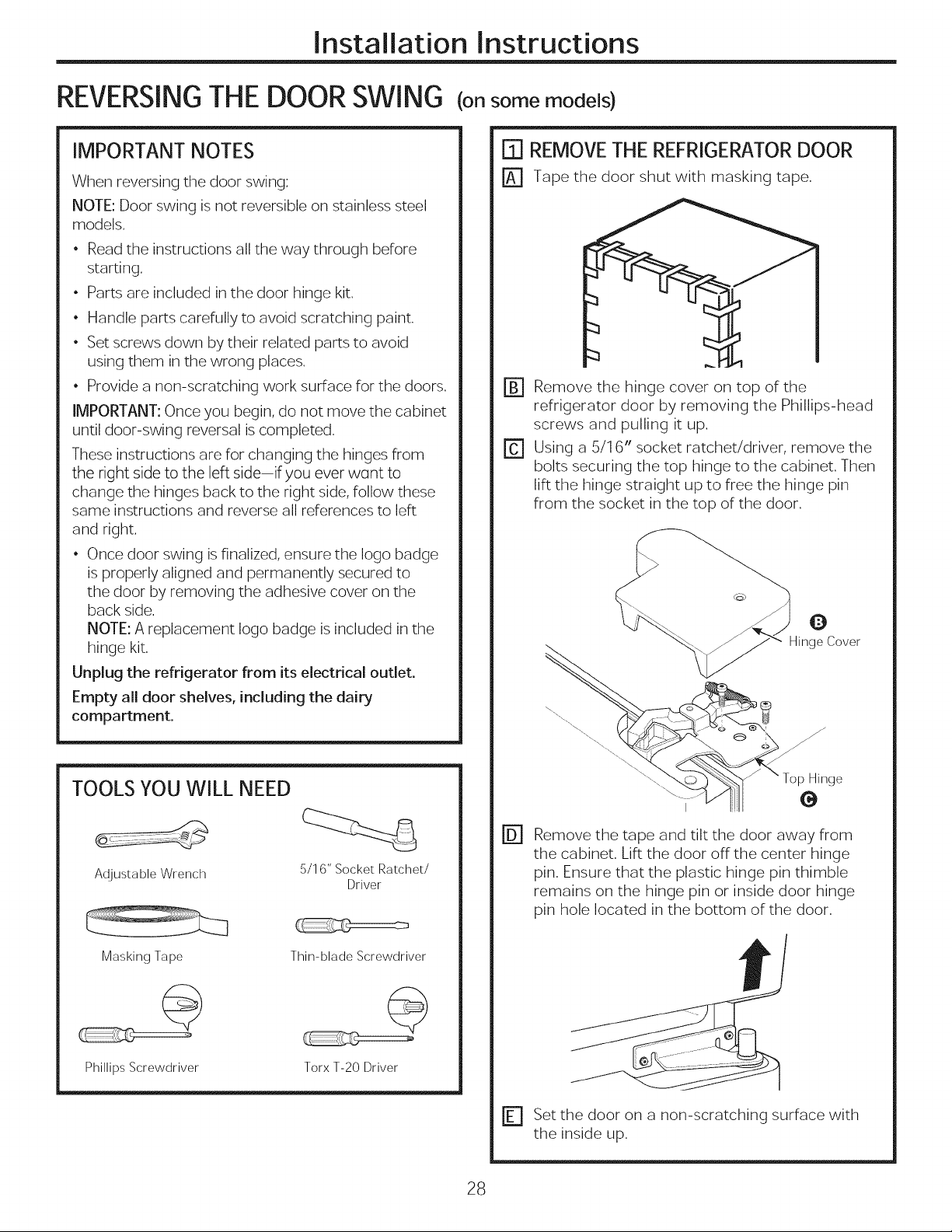
REVERSINGTHE DOOR SWING (onsome models)
IMPORTANT NOTES
When reversing the door swing:
NOTE: Door swing is not reversible on stainless steel
models.
• Read the instructions all the way through before
starting.
• Parts are included in the door hinge kit.
• Handle parts carefully to avoid scratching paint.
• Set screws down by their related parts to avoid
using them in the wrong places.
• Provide a non-scratching work surface for the doors.
IMPORTANT: Once you begin, do not move the cabinet
until door-swing reversal is completed.
These instructions are for changing the hinges from
the right side to the left side-if you ever want to
change the hinges back to the right side, follow these
same instructions and reverse all references to left
and right.
• Once door swing is finalized, ensure the logo badge
is properly aligned and permanently secured to
the door by removing the adhesive cover on the
back side.
NOTE: A replacement logo badge is included inthe
hinge kit.
Unplug the refrigerator from its electrical outlet.
Empty all door shelves, including the dairy
compartment.
rT1 REMOVE THE REFRIGERATOR DOOR
[] Tape the door shut with masking tape.
1_ Remove the hinge cover on top of the
refrigerator door by removing the Phillips-head
screws and pulling it up.
E] Using a 5/1 6" socket ratchet/driver, remove the
bolts securing the top hinge to the cabinet. Then
lift the hinge straight up to free the hinge pin
from the socket in the top of the door.
TOOLS YOU WILL NEED
Adjustable Wrench
Masking Tape
@
Phillips Screwdriver
5/16" Socket Ratchet/
Driver
Thin-blade Screwdriver
©
TorxT-20Driver
@ Remove the tape and tilt the door away from
the cabinet. Lift the door offthe center hinge
pin. Ensure that the plastic hinge pin thimble
remains on the hinge pin or inside door hinge
pin hole located in the bottom of the door.
r_ Set the door on a non-scratching surface with
the inside up.
28
Installation Instructions
REVERSINGTHE DOOR SWING (cont.)
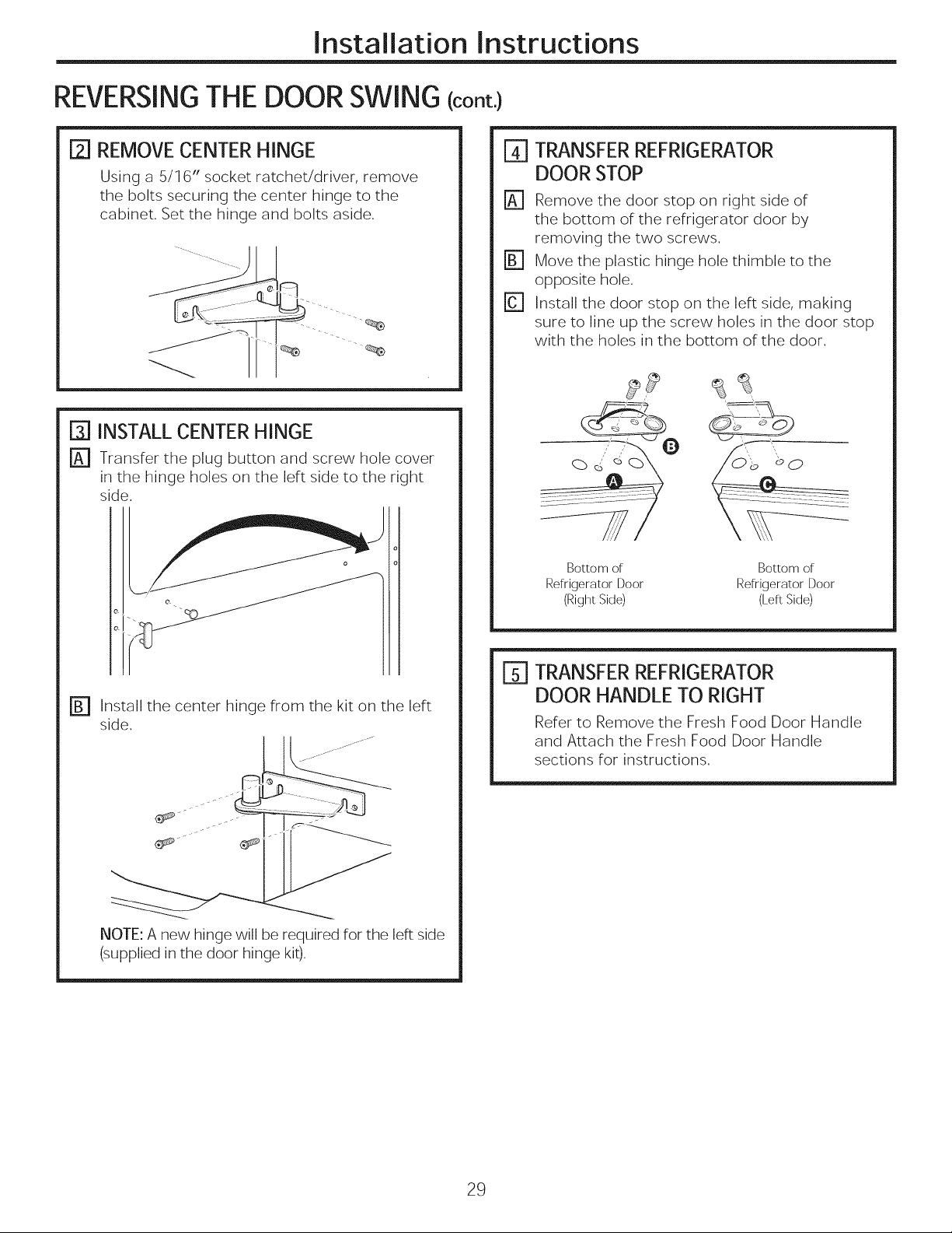
[2] REMOVECENTERHINGE
Using a 5/1 6" socket ratchet/driver, remove
the bolts securing the center hinge to the
cabinet. Set the hinge and bolts aside.
1-33INSTALLCENTERHINGE
[] Transfer the plug button and screw hole cover
in the hinge holes on the left side to the right
side.
o
o
e_
TRANSFERREFRIGERATOR
%
DOOR STOP
%
Remove the door stop on right side of
the bottom of the refrigerator door by
removing the two screws.
Move the plastic hinge hole thimble to the
opposite hole.
Install the door stop on the left side, making
sure to line up the screw holes in the door stop
with the holes in the bottom of the door.
Bottom of Bottom of
Refrigerator Door Refrigerator Door
(Right Side) (Left Side)
r_ Install the center hinge from the kit on the left
side.
.... oo J°°J° ....
NOTE: A new hinge will be required for the left side
(supplied in the door hinge kit).
E] TRANSFER REFRIGERATOR
DOOR HANDLE TO RIGHT
Refer to Remove the Fresh Food Door Handle
and Attach the Fresh Food Door Handle
sections for instructions.
29
Installation Instructions
REVERSINGTHE DOOR SWING (cont.)
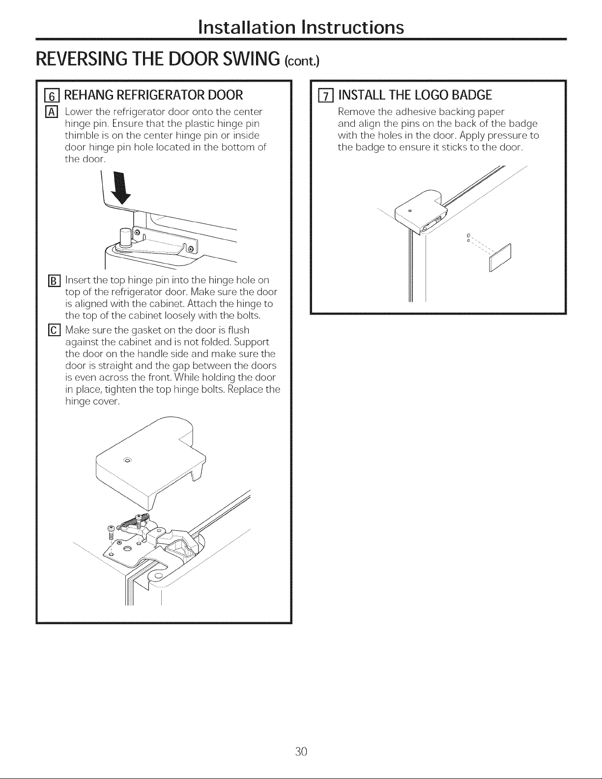
ITI REHANG REFRIGERATOR DOOR
r_ Lower the refrigerator door onto the center
hinge pin. Ensure that the plastic hinge pin
thimble is on the center hinge pin or inside
door hinge pin hole located in the bottom of
the door.
Insert the top hinge pin into the hinge hole on
top of the refrigerator door. Make sure the door
is aligned with the cabinet. Attach the hinge to
the top of the cabinet loosely with the bolts.
D
Make sure the gasket on the door is flush
against the cabinet and is not folded. Support
the door on the handle side and make sure the
door is straight and the gap between the doors
is even across the front. While holding the door
in place, tighten the top hinge bolts. Replace the
hinge cover.
ITI INSTALL THE LOGO BADGE
Remove the adhesive backing paper
and align the pins on the back of the badge
with the holes in the door. Apply pressure to
the badge to ensure it sticks to the door.
j
0
3O
 Loading...