


CIC Pro™
Clinical Information Center
Service Manual
(Software Version 4)
2001099-145 Revision D

NOTE: Due to continuing product innovation, specifications in this manual are subject to change without notice.
Listed below are GE Medical Systems Information Technologies trademarks used in this manual. All other trademarks
contained herein are the property of their respective owners.
UNITY NETWORK, ApexPro, CD TELEMETRY, and RSVP are trademarks of GE Medical Systems Information
Technologies registered in the United States Patent and Trademark Office.
CD TELEMETRY
®
–LAN, CENTRALSCOPE, CIC Pro, ICMMS, Prism, Octacomm, and Octanet are trademarks of GE
Medical Systems Information Technologies.
© 2004 - 2005 General Electric Company. All rights reserved.
T-2 CIC Pro Revision D
2001099-145 6 April 2005

Contents
1 Introduction . . . . . . . . . . . . . . . . . . . . . . . . . . . . . . . . . . . . 1-1
License Agreement . . . . . . . . . . . . . . . . . . . . . . . . . . . . . . . . . . . . . . . . . . . . . . . . . . 1-3
Manual Information . . . . . . . . . . . . . . . . . . . . . . . . . . . . . . . . . . . . . . . . . . . . . . . . . . 1-6
Revision History . . . . . . . . . . . . . . . . . . . . . . . . . . . . . . . . . . . . . . . . . . . . . . . . . . .1-6
Manual Purpose . . . . . . . . . . . . . . . . . . . . . . . . . . . . . . . . . . . . . . . . . . . . . . . . . . .1-6
Intended Audience . . . . . . . . . . . . . . . . . . . . . . . . . . . . . . . . . . . . . . . . . . . . . . . . .1-6
Safety Information . . . . . . . . . . . . . . . . . . . . . . . . . . . . . . . . . . . . . . . . . . . . . . . . . . . 1-7
Responsibility of the Manufacturer . . . . . . . . . . . . . . . . . . . . . . . . . . . . . . . . . . . . .1-7
Intended Use . . . . . . . . . . . . . . . . . . . . . . . . . . . . . . . . . . . . . . . . . . . . . . . . . . . . .1-7
Hazard Definitions . . . . . . . . . . . . . . . . . . . . . . . . . . . . . . . . . . . . . . . . . . . . . . . . .1-8
Definitions . . . . . . . . . . . . . . . . . . . . . . . . . . . . . . . . . . . . . . . . . . . . . . . . . . . . . . .1-9
Equipment Symbols . . . . . . . . . . . . . . . . . . . . . . . . . . . . . . . . . . . . . . . . . . . . . . . . 1-11
Service Information . . . . . . . . . . . . . . . . . . . . . . . . . . . . . . . . . . . . . . . . . . . . . . . . . 1-12
Service Requirements . . . . . . . . . . . . . . . . . . . . . . . . . . . . . . . . . . . . . . . . . . . . .1-12
Equipment Identification . . . . . . . . . . . . . . . . . . . . . . . . . . . . . . . . . . . . . . . . . . . .1-12
2 Equipment Description . . . . . . . . . . . . . . . . . . . . . . . . . . . 2-1
Unity Network Description/Connection . . . . . . . . . . . . . . . . . . . . . . . . . . . . . . . . . . 2-3
Unity Network MC . . . . . . . . . . . . . . . . . . . . . . . . . . . . . . . . . . . . . . . . . . . . . . . . .2-3
Unity Network IX . . . . . . . . . . . . . . . . . . . . . . . . . . . . . . . . . . . . . . . . . . . . . . . . . .2-3
Unity Network RX . . . . . . . . . . . . . . . . . . . . . . . . . . . . . . . . . . . . . . . . . . . . . . . . . .2-3
Network Connections . . . . . . . . . . . . . . . . . . . . . . . . . . . . . . . . . . . . . . . . . . . . . . .2-3
Theory of Operation . . . . . . . . . . . . . . . . . . . . . . . . . . . . . . . . . . . . . . . . . . . . . . . . . . 2-4
CIC Pro Functional Description . . . . . . . . . . . . . . . . . . . . . . . . . . . . . . . . . . . . . . .2-4
ApexPro Telemetry System Functional Description . . . . . . . . . . . . . . . . . . . . . . . .2-4
How Trends are Calculated . . . . . . . . . . . . . . . . . . . . . . . . . . . . . . . . . . . . . . . . . .2-4
File/Data Handling . . . . . . . . . . . . . . . . . . . . . . . . . . . . . . . . . . . . . . . . . . . . . . . . .2-5
Full Disclosure . . . . . . . . . . . . . . . . . . . . . . . . . . . . . . . . . . . . . . . . . . . . . . . . . . . .2-6
CIC Pro Service Logons . . . . . . . . . . . . . . . . . . . . . . . . . . . . . . . . . . . . . . . . . . . . . 2-13
Full-Access Logons . . . . . . . . . . . . . . . . . . . . . . . . . . . . . . . . . . . . . . . . . . . . . . .2-13
Limited-Access Logon . . . . . . . . . . . . . . . . . . . . . . . . . . . . . . . . . . . . . . . . . . . . .2-14
Run-Time Logon . . . . . . . . . . . . . . . . . . . . . . . . . . . . . . . . . . . . . . . . . . . . . . . . .2-14
Service Mode Logon . . . . . . . . . . . . . . . . . . . . . . . . . . . . . . . . . . . . . . . . . . . . . .2-14
CIC Pro and ApexPro Host Components . . . . . . . . . . . . . . . . . . . . . . . . . . . . . . . . 2-15
Hardware . . . . . . . . . . . . . . . . . . . . . . . . . . . . . . . . . . . . . . . . . . . . . . . . . . . . . . .2-15
CIC Pro with ApexPro Telemetry System Host . . . . . . . . . . . . . . . . . . . . . . . . . .2-16
Revision D CIC Pro i
2001099-145

CIC Pro IP Address Information . . . . . . . . . . . . . . . . . . . . . . . . . . . . . . . . . . . . . . . 2-17
Display All IP Addresses . . . . . . . . . . . . . . . . . . . . . . . . . . . . . . . . . . . . . . . . . . .2-17
CIC Pro Network Cards . . . . . . . . . . . . . . . . . . . . . . . . . . . . . . . . . . . . . . . . . . . .2-18
CIC Pro Telemetry Tower Option . . . . . . . . . . . . . . . . . . . . . . . . . . . . . . . . . . . . . . 2-19
CIC Pro Full Disclosure License Management Setup . . . . . . . . . . . . . . . . . . . . . 2-20
BCM Server . . . . . . . . . . . . . . . . . . . . . . . . . . . . . . . . . . . . . . . . . . . . . . . . . . . . .2-20
Server Without Full Disclosure . . . . . . . . . . . . . . . . . . . . . . . . . . . . . . . . . . . . . . .2-20
ApexPro PTSCONFIG Utility . . . . . . . . . . . . . . . . . . . . . . . . . . . . . . . . . . . . . . . . . . 2-21
display Commands . . . . . . . . . . . . . . . . . . . . . . . . . . . . . . . . . . . . . . . . . . . . . . .2-21
modify Command . . . . . . . . . . . . . . . . . . . . . . . . . . . . . . . . . . . . . . . . . . . . . . . . .2-22
listwhat Command . . . . . . . . . . . . . . . . . . . . . . . . . . . . . . . . . . . . . . . . . . . . . . . .2-22
Other Commands . . . . . . . . . . . . . . . . . . . . . . . . . . . . . . . . . . . . . . . . . . . . . . . . .2-22
3 Installation & Configuration . . . . . . . . . . . . . . . . . . . . . . . 3-1
Pre-Installation Requirements . . . . . . . . . . . . . . . . . . . . . . . . . . . . . . . . . . . . . . . . . 3-3
Site Requirements . . . . . . . . . . . . . . . . . . . . . . . . . . . . . . . . . . . . . . . . . . . . . . . . .3-3
Power Requirements . . . . . . . . . . . . . . . . . . . . . . . . . . . . . . . . . . . . . . . . . . . . . . .3-5
Equipment Grounding . . . . . . . . . . . . . . . . . . . . . . . . . . . . . . . . . . . . . . . . . . . . . .3-7
CIC Pro Installation . . . . . . . . . . . . . . . . . . . . . . . . . . . . . . . . . . . . . . . . . . . . . . . . . . 3-8
Pre-Installation Check . . . . . . . . . . . . . . . . . . . . . . . . . . . . . . . . . . . . . . . . . . . . . .3-9
Connect Keyboard and Mouse . . . . . . . . . . . . . . . . . . . . . . . . . . . . . . . . . . . . . .3-10
Install the Speakers . . . . . . . . . . . . . . . . . . . . . . . . . . . . . . . . . . . . . . . . . . . . . . .3-11
Install the Power Cord . . . . . . . . . . . . . . . . . . . . . . . . . . . . . . . . . . . . . . . . . . . . .3-12
Connect the Video Display Monitor . . . . . . . . . . . . . . . . . . . . . . . . . . . . . . . . . . .3-13
Connect the Digital Writer Printer . . . . . . . . . . . . . . . . . . . . . . . . . . . . . . . . . . . .3-14
ApexPro Option Installation . . . . . . . . . . . . . . . . . . . . . . . . . . . . . . . . . . . . . . . . . . 3-15
CIC Pro Configuration . . . . . . . . . . . . . . . . . . . . . . . . . . . . . . . . . . . . . . . . . . . . . . . 3-15
Configure Time/Date Settings . . . . . . . . . . . . . . . . . . . . . . . . . . . . . . . . . . . . . . .3-15
Connect to Unity Network . . . . . . . . . . . . . . . . . . . . . . . . . . . . . . . . . . . . . . . . . .3-19
Install Optional Licenses . . . . . . . . . . . . . . . . . . . . . . . . . . . . . . . . . . . . . . . . . . .3-19
Install a Printer . . . . . . . . . . . . . . . . . . . . . . . . . . . . . . . . . . . . . . . . . . . . . . . . . . .3-20
Setup the CIC Pro . . . . . . . . . . . . . . . . . . . . . . . . . . . . . . . . . . . . . . . . . . . . . . . .3-24
Lock or Unlock Beds . . . . . . . . . . . . . . . . . . . . . . . . . . . . . . . . . . . . . . . . . . . . . .3-41
Browser Setup . . . . . . . . . . . . . . . . . . . . . . . . . . . . . . . . . . . . . . . . . . . . . . . . . . . . . 3-42
Configure Browser . . . . . . . . . . . . . . . . . . . . . . . . . . . . . . . . . . . . . . . . . . . . . . . .3-42
IP Address Configuration . . . . . . . . . . . . . . . . . . . . . . . . . . . . . . . . . . . . . . . . . . . . 3-44
ApexPro Configuration . . . . . . . . . . . . . . . . . . . . . . . . . . . . . . . . . . . . . . . . . . . . . . 3-47
Using the ptsconfig Utility . . . . . . . . . . . . . . . . . . . . . . . . . . . . . . . . . . . . . . . . . . .3-47
Dual Monitor Installation and Configuration . . . . . . . . . . . . . . . . . . . . . . . . . . . . . 3-49
Dual Monitor Installation . . . . . . . . . . . . . . . . . . . . . . . . . . . . . . . . . . . . . . . . . . .3-49
Dual Monitor Configuration . . . . . . . . . . . . . . . . . . . . . . . . . . . . . . . . . . . . . . . . .3-50
Test Browser Function with Dual Monitors . . . . . . . . . . . . . . . . . . . . . . . . . . . . .3-51
ii CIC Pro Revision D
2001099-145

Removing One Monitor From a Dual Monitor System . . . . . . . . . . . . . . . . . . . . .3-52
In-Unit Incompatibility (CIC Pro v4.0.7 Only) . . . . . . . . . . . . . . . . . . . . . . . . . . . . . 3-52
Care Units with Multiple CIC Pros Telemetry Defaults Upgrade . . . . . . . . . . . . .3-53
Completion . . . . . . . . . . . . . . . . . . . . . . . . . . . . . . . . . . . . . . . . . . . . . . . . . . . . . . . . 3-54
4 Maintenance . . . . . . . . . . . . . . . . . . . . . . . . . . . . . . . . . . . 4-1
Schedule . . . . . . . . . . . . . . . . . . . . . . . . . . . . . . . . . . . . . . . . . . . . . . . . . . . . . . . . . . . 4-3
Manufacturer Recommendation . . . . . . . . . . . . . . . . . . . . . . . . . . . . . . . . . . . . . . .4-3
PM Form . . . . . . . . . . . . . . . . . . . . . . . . . . . . . . . . . . . . . . . . . . . . . . . . . . . . . . . .4-3
System Resource Management . . . . . . . . . . . . . . . . . . . . . . . . . . . . . . . . . . . . . . . . 4-4
System Resource Reset . . . . . . . . . . . . . . . . . . . . . . . . . . . . . . . . . . . . . . . . . . . .4-5
Visual Inspection . . . . . . . . . . . . . . . . . . . . . . . . . . . . . . . . . . . . . . . . . . . . . . . . . . . . 4-6
About the Visual Inspection . . . . . . . . . . . . . . . . . . . . . . . . . . . . . . . . . . . . . . . . . .4-6
Procedure . . . . . . . . . . . . . . . . . . . . . . . . . . . . . . . . . . . . . . . . . . . . . . . . . . . . . . .4-6
Cleaning . . . . . . . . . . . . . . . . . . . . . . . . . . . . . . . . . . . . . . . . . . . . . . . . . . . . . . . . . . . 4-7
General Rules . . . . . . . . . . . . . . . . . . . . . . . . . . . . . . . . . . . . . . . . . . . . . . . . . . . .4-7
Cleaning Procedure . . . . . . . . . . . . . . . . . . . . . . . . . . . . . . . . . . . . . . . . . . . . . . . .4-7
Display Screen . . . . . . . . . . . . . . . . . . . . . . . . . . . . . . . . . . . . . . . . . . . . . . . . . . . .4-8
Electrical Safety Tests . . . . . . . . . . . . . . . . . . . . . . . . . . . . . . . . . . . . . . . . . . . . . . . . 4-9
General . . . . . . . . . . . . . . . . . . . . . . . . . . . . . . . . . . . . . . . . . . . . . . . . . . . . . . . . .4-9
Recommendations . . . . . . . . . . . . . . . . . . . . . . . . . . . . . . . . . . . . . . . . . . . . . . . . .4-9
Wall Receptacle Test . . . . . . . . . . . . . . . . . . . . . . . . . . . . . . . . . . . . . . . . . . . . . .4-10
Ground (Earth) Integrity . . . . . . . . . . . . . . . . . . . . . . . . . . . . . . . . . . . . . . . . . . . .4-10
Ground (Earth) Wire Leakage Current Tests . . . . . . . . . . . . . . . . . . . . . . . . . . . .4-11
Enclosure (Chassis) Leakage Current Test . . . . . . . . . . . . . . . . . . . . . . . . . . . . .4-12
Test Completion . . . . . . . . . . . . . . . . . . . . . . . . . . . . . . . . . . . . . . . . . . . . . . . . . .4-13
Checkout Procedure . . . . . . . . . . . . . . . . . . . . . . . . . . . . . . . . . . . . . . . . . . . . . . . . 4-14
About the Checkout Procedure . . . . . . . . . . . . . . . . . . . . . . . . . . . . . . . . . . . . . .4-14
Instructions . . . . . . . . . . . . . . . . . . . . . . . . . . . . . . . . . . . . . . . . . . . . . . . . . . . . . .4-14
Repair Log . . . . . . . . . . . . . . . . . . . . . . . . . . . . . . . . . . . . . . . . . . . . . . . . . . . . . . . . 4-19
5 Nightshade Server Field Replacement Procedures . . . . 5-1
Field Replacement Preparation . . . . . . . . . . . . . . . . . . . . . . . . . . . . . . . . . . . . . . . . 5-3
Nightshade Server Hard Drive Replacement . . . . . . . . . . . . . . . . . . . . . . . . . . . . . . 5-4
Overview . . . . . . . . . . . . . . . . . . . . . . . . . . . . . . . . . . . . . . . . . . . . . . . . . . . . . . . .5-4
Record Configuration Information . . . . . . . . . . . . . . . . . . . . . . . . . . . . . . . . . . . . .5-4
Remove and Install Nightshade Server Hard Drive . . . . . . . . . . . . . . . . . . . . . . . .5-8
Install Gold Drive Image . . . . . . . . . . . . . . . . . . . . . . . . . . . . . . . . . . . . . . . . . . . .5-10
Configure Gold Drive to Product Drive (G2P) . . . . . . . . . . . . . . . . . . . . . . . . . . .5-10
Revision D CIC Pro iii
2001099-145

6 BCM Server Field Replacement Procedures . . . . . . . . . 6-1
CIC Pro Field Replacement Procedures . . . . . . . . . . . . . . . . . . . . . . . . . . . . . . . . . 6-3
Field Replacement Preparation . . . . . . . . . . . . . . . . . . . . . . . . . . . . . . . . . . . . . . . . 6-4
Side Panel Removal/Installation . . . . . . . . . . . . . . . . . . . . . . . . . . . . . . . . . . . . . . . . 6-5
Side Panel Removal . . . . . . . . . . . . . . . . . . . . . . . . . . . . . . . . . . . . . . . . . . . . . . .6-5
Side Panel Installation . . . . . . . . . . . . . . . . . . . . . . . . . . . . . . . . . . . . . . . . . . . . . .6-5
Front Bezel Removal/Installation . . . . . . . . . . . . . . . . . . . . . . . . . . . . . . . . . . . . . . . 6-6
Front Bezel Removal . . . . . . . . . . . . . . . . . . . . . . . . . . . . . . . . . . . . . . . . . . . . . . .6-6
Front Bezel Installation . . . . . . . . . . . . . . . . . . . . . . . . . . . . . . . . . . . . . . . . . . . . .6-6
BCM Server Hard Drive Replacement . . . . . . . . . . . . . . . . . . . . . . . . . . . . . . . . . . . 6-7
Overview . . . . . . . . . . . . . . . . . . . . . . . . . . . . . . . . . . . . . . . . . . . . . . . . . . . . . . . .6-7
Record Configuration Information . . . . . . . . . . . . . . . . . . . . . . . . . . . . . . . . . . . . .6-7
Hard Drive Removal/Installation . . . . . . . . . . . . . . . . . . . . . . . . . . . . . . . . . . . . .6-11
Install Gold Drive Image . . . . . . . . . . . . . . . . . . . . . . . . . . . . . . . . . . . . . . . . . . . .6-13
Configure Gold Drive to Product Drive (G2P) . . . . . . . . . . . . . . . . . . . . . . . . . . .6-13
Floppy Drive Removal/Installation . . . . . . . . . . . . . . . . . . . . . . . . . . . . . . . . . . . . . 6-14
Floppy Drive Removal . . . . . . . . . . . . . . . . . . . . . . . . . . . . . . . . . . . . . . . . . . . . .6-14
Floppy Drive Installation . . . . . . . . . . . . . . . . . . . . . . . . . . . . . . . . . . . . . . . . . . . .6-15
CD Drive Removal/Installation . . . . . . . . . . . . . . . . . . . . . . . . . . . . . . . . . . . . . . . . 6-17
CD Drive Removal . . . . . . . . . . . . . . . . . . . . . . . . . . . . . . . . . . . . . . . . . . . . . . . .6-17
CD Drive Installation . . . . . . . . . . . . . . . . . . . . . . . . . . . . . . . . . . . . . . . . . . . . . .6-20
Fan Removal/Installation . . . . . . . . . . . . . . . . . . . . . . . . . . . . . . . . . . . . . . . . . . . . 6-23
Chassis Fan Removal . . . . . . . . . . . . . . . . . . . . . . . . . . . . . . . . . . . . . . . . . . . . .6-23
Chassis Fan Installation . . . . . . . . . . . . . . . . . . . . . . . . . . . . . . . . . . . . . . . . . . . .6-24
CPU Fan Removal . . . . . . . . . . . . . . . . . . . . . . . . . . . . . . . . . . . . . . . . . . . . . . . .6-27
CPU Fan Installation . . . . . . . . . . . . . . . . . . . . . . . . . . . . . . . . . . . . . . . . . . . . . .6-28
Video Card Removal/Installation . . . . . . . . . . . . . . . . . . . . . . . . . . . . . . . . . . . . . . 6-29
Video Card Removal . . . . . . . . . . . . . . . . . . . . . . . . . . . . . . . . . . . . . . . . . . . . . .6-29
Video Card Installation . . . . . . . . . . . . . . . . . . . . . . . . . . . . . . . . . . . . . . . . . . . . .6-31
RX Network Card Removal/Replacement . . . . . . . . . . . . . . . . . . . . . . . . . . . . . . . 6-33
RX Network Card Removal . . . . . . . . . . . . . . . . . . . . . . . . . . . . . . . . . . . . . . . . .6-33
RX Network Card Installation . . . . . . . . . . . . . . . . . . . . . . . . . . . . . . . . . . . . . . . .6-35
Audio Card Removal/Installation . . . . . . . . . . . . . . . . . . . . . . . . . . . . . . . . . . . . . . 6-37
Audio Card Removal . . . . . . . . . . . . . . . . . . . . . . . . . . . . . . . . . . . . . . . . . . . . . .6-37
Audio Card Installation . . . . . . . . . . . . . . . . . . . . . . . . . . . . . . . . . . . . . . . . . . . . .6-39
Watchdog Card Removal/Installation . . . . . . . . . . . . . . . . . . . . . . . . . . . . . . . . . . 6-41
Watchdog Card Removal . . . . . . . . . . . . . . . . . . . . . . . . . . . . . . . . . . . . . . . . . . .6-41
Watchdog Card Installation . . . . . . . . . . . . . . . . . . . . . . . . . . . . . . . . . . . . . . . . .6-43
Motherboard Removal/Installation . . . . . . . . . . . . . . . . . . . . . . . . . . . . . . . . . . . . . 6-47
Motherboard Removal . . . . . . . . . . . . . . . . . . . . . . . . . . . . . . . . . . . . . . . . . . . . .6-47
Motherboard Installation . . . . . . . . . . . . . . . . . . . . . . . . . . . . . . . . . . . . . . . . . . .6-53
iv CIC Pro Revision D
2001099-145

Power Supply Removal/Installation . . . . . . . . . . . . . . . . . . . . . . . . . . . . . . . . . . . . 6-62
Power Supply Removal . . . . . . . . . . . . . . . . . . . . . . . . . . . . . . . . . . . . . . . . . . . .6-62
Power Supply Installation . . . . . . . . . . . . . . . . . . . . . . . . . . . . . . . . . . . . . . . . . . .6-65
Power Switch Removal/Installation . . . . . . . . . . . . . . . . . . . . . . . . . . . . . . . . . . . . 6-70
Power Switch Removal . . . . . . . . . . . . . . . . . . . . . . . . . . . . . . . . . . . . . . . . . . . .6-70
Power Switch Installation . . . . . . . . . . . . . . . . . . . . . . . . . . . . . . . . . . . . . . . . . . .6-75
7 Webmin Application . . . . . . . . . . . . . . . . . . . . . . . . . . . . . 7-1
Introduction . . . . . . . . . . . . . . . . . . . . . . . . . . . . . . . . . . . . . . . . . . . . . . . . . . . . . . . . 7-3
Webmin Access . . . . . . . . . . . . . . . . . . . . . . . . . . . . . . . . . . . . . . . . . . . . . . . . . . .7-3
Webmin Login . . . . . . . . . . . . . . . . . . . . . . . . . . . . . . . . . . . . . . . . . . . . . . . . . . . .7-3
Webmin Tabs . . . . . . . . . . . . . . . . . . . . . . . . . . . . . . . . . . . . . . . . . . . . . . . . . . . . .7-5
System Tab . . . . . . . . . . . . . . . . . . . . . . . . . . . . . . . . . . . . . . . . . . . . . . . . . . . . . . . . . 7-6
Overview . . . . . . . . . . . . . . . . . . . . . . . . . . . . . . . . . . . . . . . . . . . . . . . . . . . . . . . .7-6
Asset Management . . . . . . . . . . . . . . . . . . . . . . . . . . . . . . . . . . . . . . . . . . . . . . . .7-6
Download Logs . . . . . . . . . . . . . . . . . . . . . . . . . . . . . . . . . . . . . . . . . . . . . . . . . .7-11
Set IP Address . . . . . . . . . . . . . . . . . . . . . . . . . . . . . . . . . . . . . . . . . . . . . . . . . . .7-13
View System Information . . . . . . . . . . . . . . . . . . . . . . . . . . . . . . . . . . . . . . . . . . .7-15
View Logs . . . . . . . . . . . . . . . . . . . . . . . . . . . . . . . . . . . . . . . . . . . . . . . . . . . . . .7-16
View Unity Devices . . . . . . . . . . . . . . . . . . . . . . . . . . . . . . . . . . . . . . . . . . . . . . .7-17
CIC Tab . . . . . . . . . . . . . . . . . . . . . . . . . . . . . . . . . . . . . . . . . . . . . . . . . . . . . . . . . . . 7-19
Webmin CIC Application Windows . . . . . . . . . . . . . . . . . . . . . . . . . . . . . . . . . . .7-20
ApexPro Tab . . . . . . . . . . . . . . . . . . . . . . . . . . . . . . . . . . . . . . . . . . . . . . . . . . . . . . . 7-40
8 Troubleshooting . . . . . . . . . . . . . . . . . . . . . . . . . . . . . . . . 8-1
Hardware General . . . . . . . . . . . . . . . . . . . . . . . . . . . . . . . . . . . . . . . . . . . . . . . . . . . 8-3
Blank Display, Unit Doesn’t Boot . . . . . . . . . . . . . . . . . . . . . . . . . . . . . . . . . . . . . .8-3
Troubleshooting the Components . . . . . . . . . . . . . . . . . . . . . . . . . . . . . . . . . . . . .8-3
Troubleshooting Dual Monitors . . . . . . . . . . . . . . . . . . . . . . . . . . . . . . . . . . . . . . .8-3
Controlling Electrostatic Discharge Damage . . . . . . . . . . . . . . . . . . . . . . . . . . . . .8-4
Accessing Service Utilities . . . . . . . . . . . . . . . . . . . . . . . . . . . . . . . . . . . . . . . . . . . . 8-6
Command Prompt . . . . . . . . . . . . . . . . . . . . . . . . . . . . . . . . . . . . . . . . . . . . . . . . .8-6
CIC Pro Log Files . . . . . . . . . . . . . . . . . . . . . . . . . . . . . . . . . . . . . . . . . . . . . . . . . .8-6
CIC Pro In-Unit Incompatibility . . . . . . . . . . . . . . . . . . . . . . . . . . . . . . . . . . . . . . . . . 8-8
Browser Troubleshooting . . . . . . . . . . . . . . . . . . . . . . . . . . . . . . . . . . . . . . . . . . . . . 8-8
Use a Command Prompt to Connect to a Site . . . . . . . . . . . . . . . . . . . . . . . . . . . .8 -9
Address Field Entries . . . . . . . . . . . . . . . . . . . . . . . . . . . . . . . . . . . . . . . . . . . . . .8-10
Specific Web Applications . . . . . . . . . . . . . . . . . . . . . . . . . . . . . . . . . . . . . . . . . .8-10
Troubleshooting a CIC Pro Server Tower . . . . . . . . . . . . . . . . . . . . . . . . . . . . . . . 8-12
Intel Server Control (ISC–Nightshade Box Only) . . . . . . . . . . . . . . . . . . . . . . . . .8-12
Revision D CIC Pro v
2001099-145

DMI Error Message (Nightshade Box Only) . . . . . . . . . . . . . . . . . . . . . . . . . . . . . 8-14
Canceling CIC Pro Print Jobs . . . . . . . . . . . . . . . . . . . . . . . . . . . . . . . . . . . . . . . . . 8-18
Capture All Logs on the CIC Pro . . . . . . . . . . . . . . . . . . . . . . . . . . . . . . . . . . . . . . 8-19
Use the Get All Logs Tool . . . . . . . . . . . . . . . . . . . . . . . . . . . . . . . . . . . . . . . . . .8-19
FileSplit . . . . . . . . . . . . . . . . . . . . . . . . . . . . . . . . . . . . . . . . . . . . . . . . . . . . . . . .8-23
Duplicate TTX . . . . . . . . . . . . . . . . . . . . . . . . . . . . . . . . . . . . . . . . . . . . . . . . . . .8-23
List Network . . . . . . . . . . . . . . . . . . . . . . . . . . . . . . . . . . . . . . . . . . . . . . . . . . . . .8-24
Open RTERM Session . . . . . . . . . . . . . . . . . . . . . . . . . . . . . . . . . . . . . . . . . . . . .8-25
Copying CDT LAN Telemetry Logs From CIC Pro . . . . . . . . . . . . . . . . . . . . . . .8-26
ApexPro Application Log Files . . . . . . . . . . . . . . . . . . . . . . . . . . . . . . . . . . . . . . . . 8-27
File Handling . . . . . . . . . . . . . . . . . . . . . . . . . . . . . . . . . . . . . . . . . . . . . . . . . . . . . . 8-28
General . . . . . . . . . . . . . . . . . . . . . . . . . . . . . . . . . . . . . . . . . . . . . . . . . . . . . . . .8-28
Towers, ApexPro and CIC Pro . . . . . . . . . . . . . . . . . . . . . . . . . . . . . . . . . . . . . . .8-28
Admit/TTX Master . . . . . . . . . . . . . . . . . . . . . . . . . . . . . . . . . . . . . . . . . . . . . . . .8-29
Telemetry Towers, Receivers, and Unit Names . . . . . . . . . . . . . . . . . . . . . . . . .8-29
Troubleshooting the ApexPro System . . . . . . . . . . . . . . . . . . . . . . . . . . . . . . . . . 8-33
9 Assembly Drawings . . . . . . . . . . . . . . . . . . . . . . . . . . . . . 9-1
General . . . . . . . . . . . . . . . . . . . . . . . . . . . . . . . . . . . . . . . . . . . . . . . . . . . . . . . . . . . . 9-3
Back Panel Connections . . . . . . . . . . . . . . . . . . . . . . . . . . . . . . . . . . . . . . . . . . . . . . 9-4
CIC Pro Nightshade Server . . . . . . . . . . . . . . . . . . . . . . . . . . . . . . . . . . . . . . . . . .9-4
CIC Pro BCM Server . . . . . . . . . . . . . . . . . . . . . . . . . . . . . . . . . . . . . . . . . . . . . . .9-5
Server Tower . . . . . . . . . . . . . . . . . . . . . . . . . . . . . . . . . . . . . . . . . . . . . . . . . . . . . . . 9-6
Nightshade Server . . . . . . . . . . . . . . . . . . . . . . . . . . . . . . . . . . . . . . . . . . . . . . . . .9-6
BCM Server . . . . . . . . . . . . . . . . . . . . . . . . . . . . . . . . . . . . . . . . . . . . . . . . . . . . . .9-7
CIC Pro System Block Diagrams . . . . . . . . . . . . . . . . . . . . . . . . . . . . . . . . . . . . . . . 9-8
Nightshade Server . . . . . . . . . . . . . . . . . . . . . . . . . . . . . . . . . . . . . . . . . . . . . . . . .9-8
BCM Server . . . . . . . . . . . . . . . . . . . . . . . . . . . . . . . . . . . . . . . . . . . . . . . . . . . . . .9-9
CIC Pro Parts Lists . . . . . . . . . . . . . . . . . . . . . . . . . . . . . . . . . . . . . . . . . . . . . . . . . 9-10
CIC Pro Nightshade Server . . . . . . . . . . . . . . . . . . . . . . . . . . . . . . . . . . . . . . . . .9-10
CIC Pro BCM Server Field Replacement Units . . . . . . . . . . . . . . . . . . . . . . . . . .9-11
CIC Pro Keyboard Kit . . . . . . . . . . . . . . . . . . . . . . . . . . . . . . . . . . . . . . . . . . . . . .9-11
CIC Pro BCM Server . . . . . . . . . . . . . . . . . . . . . . . . . . . . . . . . . . . . . . . . . . . . . .9-12
PC Motherboard Settings . . . . . . . . . . . . . . . . . . . . . . . . . . . . . . . . . . . . . . . . . . . . 9-13
Nightshade Server Motherboard Jumper Settings . . . . . . . . . . . . . . . . . . . . . . . .9-13
CIC Pro BCM Server Motherboard Switch Settings . . . . . . . . . . . . . . . . . . . . . . .9-14
Technical Specifications . . . . . . . . . . . . . . . . . . . . . . . . . .A-1
Technical Specifications–CIC Pro . . . . . . . . . . . . . . . . . . . . . . . . . . . . . . . . . . . . . . A-3
Performance Specifications (PC) . . . . . . . . . . . . . . . . . . . . . . . . . . . . . . . . . . . . . .A-3
vi CIC Pro Revision D
2001099-145

Recorder (optional) . . . . . . . . . . . . . . . . . . . . . . . . . . . . . . . . . . . . . . . . . . . . . . . .A-3
General . . . . . . . . . . . . . . . . . . . . . . . . . . . . . . . . . . . . . . . . . . . . . . . . . . . . . . . . .A-4
Environmental Specifications (PC) . . . . . . . . . . . . . . . . . . . . . . . . . . . . . . . . . . . .A-4
Physical Specifications . . . . . . . . . . . . . . . . . . . . . . . . . . . . . . . . . . . . . . . . . . . . .A-5
Display Specifications . . . . . . . . . . . . . . . . . . . . . . . . . . . . . . . . . . . . . . . . . . . . . .A-5
Monitor (Display) Connections . . . . . . . . . . . . . . . . . . . . . . . . . . . . . . . . . . . . . . . .A-5
Certification . . . . . . . . . . . . . . . . . . . . . . . . . . . . . . . . . . . . . . . . . . . . . . . . . . . . . .A-5
Supported CIC Pro Parameters . . . . . . . . . . . . . . . . . . . . .B-1
Arterial Blood Gas (POC) . . . . . . . . . . . . . . . . . . . . . . . . . . . . . . . . . . . . . . . . . . . .B-3
Arterial Pressure . . . . . . . . . . . . . . . . . . . . . . . . . . . . . . . . . . . . . . . . . . . . . . . . . .B-3
BIS Data . . . . . . . . . . . . . . . . . . . . . . . . . . . . . . . . . . . . . . . . . . . . . . . . . . . . . . . . .B-4
Cardiac Calculations (Cardiac Calcs) . . . . . . . . . . . . . . . . . . . . . . . . . . . . . . . . . .B-4
Cardiac Output (CO) . . . . . . . . . . . . . . . . . . . . . . . . . . . . . . . . . . . . . . . . . . . . . . .B-4
Central Venous Pressure (CVP) . . . . . . . . . . . . . . . . . . . . . . . . . . . . . . . . . . . . . .B-5
Cerebral Perfusion Pressure (CPP) . . . . . . . . . . . . . . . . . . . . . . . . . . . . . . . . . . . .B-5
Continuous Cardiac Output (CCO) . . . . . . . . . . . . . . . . . . . . . . . . . . . . . . . . . . . .B-5
CO2 Parameter . . . . . . . . . . . . . . . . . . . . . . . . . . . . . . . . . . . . . . . . . . . . . . . . . . .B-5
ECG Parameters . . . . . . . . . . . . . . . . . . . . . . . . . . . . . . . . . . . . . . . . . . . . . . . . . .B-6
Episodic Temperature . . . . . . . . . . . . . . . . . . . . . . . . . . . . . . . . . . . . . . . . . . . . . .B-7
Femoral Pressure . . . . . . . . . . . . . . . . . . . . . . . . . . . . . . . . . . . . . . . . . . . . . . . . .B-7
Inter-Cranial Pressure . . . . . . . . . . . . . . . . . . . . . . . . . . . . . . . . . . . . . . . . . . . . . .B-7
Left-Arterial Pressure . . . . . . . . . . . . . . . . . . . . . . . . . . . . . . . . . . . . . . . . . . . . . .B-7
Mass Spec . . . . . . . . . . . . . . . . . . . . . . . . . . . . . . . . . . . . . . . . . . . . . . . . . . . . . . .B-7
Non-Invasive Pressure . . . . . . . . . . . . . . . . . . . . . . . . . . . . . . . . . . . . . . . . . . . . .B-8
Non-Invasive Cardiac Output . . . . . . . . . . . . . . . . . . . . . . . . . . . . . . . . . . . . . . . .B-8
Other Cardiac Parameters . . . . . . . . . . . . . . . . . . . . . . . . . . . . . . . . . . . . . . . . . .B-9
Pulmonary Artery Pressure . . . . . . . . . . . . . . . . . . . . . . . . . . . . . . . . . . . . . . . . . .B-9
Pulmonary Calculations . . . . . . . . . . . . . . . . . . . . . . . . . . . . . . . . . . . . . . . . . . . .B-9
Right Arterial Pressure . . . . . . . . . . . . . . . . . . . . . . . . . . . . . . . . . . . . . . . . . . . .B-10
Respiration Data . . . . . . . . . . . . . . . . . . . . . . . . . . . . . . . . . . . . . . . . . . . . . . . . .B-10
Respiration Mechanics . . . . . . . . . . . . . . . . . . . . . . . . . . . . . . . . . . . . . . . . . . . .B-11
SPO2 . . . . . . . . . . . . . . . . . . . . . . . . . . . . . . . . . . . . . . . . . . . . . . . . . . . . . . . . .B-11
Special Pressure . . . . . . . . . . . . . . . . . . . . . . . . . . . . . . . . . . . . . . . . . . . . . . . . .B-11
ST Parameter . . . . . . . . . . . . . . . . . . . . . . . . . . . . . . . . . . . . . . . . . . . . . . . . . . .B-12
SvO2 . . . . . . . . . . . . . . . . . . . . . . . . . . . . . . . . . . . . . . . . . . . . . . . . . . . . . . . . . .B-12
Transcutaneous CO2 . . . . . . . . . . . . . . . . . . . . . . . . . . . . . . . . . . . . . . . . . . . . .B-12
TramModule Transcutaneous CO2 . . . . . . . . . . . . . . . . . . . . . . . . . . . . . . . . . . .B-13
Temperature . . . . . . . . . . . . . . . . . . . . . . . . . . . . . . . . . . . . . . . . . . . . . . . . . . . .B-13
Umbilical Pressure (UAC) . . . . . . . . . . . . . . . . . . . . . . . . . . . . . . . . . . . . . . . . . .B-13
Umbilical (UV, UVC) . . . . . . . . . . . . . . . . . . . . . . . . . . . . . . . . . . . . . . . . . . . . . .B-13
Ventilator Data . . . . . . . . . . . . . . . . . . . . . . . . . . . . . . . . . . . . . . . . . . . . . . . . . .B-14
Revision D CIC Pro vii
2001099-145

For your notes
viii CIC Pro Revision D
2001099-145

1 Introduction
Revision D CIC Pro 1-1
2001099-145

For your notes
1-2 CIC Pro Revision D
2001099-145

License Agreement
IT IS IMPORTANT THAT YOU CAREFULLY READ THE TERMS AND
CONDITIONS OF THIS LICENSE AGREEMENT BEFORE COMMENCING
THE USE OF THE CLINICAL INFORMATION CENTER WORKSTATION
(THE “WORKSTATION”) AND THE CLINICAL INFORMATION CENTER
PROGRAM RECORDED THEREIN AND ANY ACCOMPANYING USER
DOCUMENTATION (“PROGRAM”). THIS LICENSE REPRESENTS THE
ENTIRE LICENSE AGREEMENT CONCERNING THE PROGRAM BETWEEN
YOU AND GE MEDICAL SYSTEMS INFORMATION TECHNOLOGIES
(“INFORMATION TECHNOLOGIES”) AND SUPERSEDES ALL OTHER
COMMUNICATIONS OR ADVERTISING RELATED TO THE PROGRAM
EXCEPT ANY TERMS AND CONDITIONS OF SALE OR WARRANTIES OR
WARRANTY LIMITATIONS RELATIVE TO THE PROGRAM AND/OR THE
WORKSTATION AS MAY BE EMBODIED IN ANY DOCUMENTATION
SUPPLIED WITH THE WORKSTATION. BY COMMENCING THE USE OF
THE WORKSTATION AND THE PROGRAM CONTAINED THEREIN, YOU
ARE ACCEPTING AND AGREEING TO BE BOUND BY ALL THE TERMS
AND CONDITIONS OF THIS LICENSE AGREEMENT. IF YOU ARE NOT
WILLING TO BE BOUND BY THE TERMS AND CONDITIONS OF THIS
LICENSE AGREEMENT, YOU SHOULD PROMPTLY RETURN THE
WORKSTATION TO GE Medical Systems Information Technologies AND YOU
WILL RECEIVE A REFUND OF THE PURCHASE PRICE.
Introduction: License Agreement
I. GRANT
The Program is capable of coupling one to sixteen patient monitoring units to
the Workstation. GE Medical Systems Information Technologies hereby grants
you a non-exclusive, non-transferable right and license to use the Program for
coupling the number of patient monitoring units to the W orkstation for which a
per-unit royalty has been paid pursuant to Article II hereof.
II. ROYALTY
You have paid GE Medical Systems Information Technologies a one-time, perunit royalty equal to GE Medical Systems Information Technologies’ current
published price for the use of the Program. The per-unit royalty is based on the
actual number of patient monitors intended to be coupled by the Program to the
Workstation as stated in the Purchase Order for the Workstation and the
Program. If you use the Program to couple any patient monitoring units to the
Workstation in addition to the number for which a per unit royalty was
previously paid, you agree to pay GE Medical Systems Information
Technologies an additional per-unit royalty equal to GE Medical Systems
Information Technologies' then current published royalty for the Program for
each such additional patient monitoring unit so coupled. The additional per-unit
royalty shall be paid to GE Medical Systems Information Technologies within
30 days of the use of the Program to couple any such additional patient
monitoring units to the Workstation.
III. LIMITATIONS
You hereby agree not to: (1) use the Program in any network or system other
than to couple patient monitoring units to the Workstation; (2) make any copy
of the Program for any reason, or allow or assist others to do so; (3) modify,
reverse engineer, de compile or disassemble the Program or merge any part of
the Program into any other program; (4) rent, sell, sublease, assign, transfer or
Revision D CIC Pro 1-3
2001099-145

Introduction: License Agreement
otherwise share the Program or any of your rights in the Program under thi s
Agreement with any third party; or, (5) remove or alter any copyright notice,
labels or trademarks from the Program or the Workstation.
IV. TITLE
This License is not a sale. Title and all copyrights to the Program and any copy
made by you remains the sole property of GE Medical Systems Information
Technologies.
V. TERM
This Agreement shall continue in force until terminated. This Agreement shall
terminate automatically when you cease using the Workstation and the Program
for their intended purpose. GE Medical Systems Information Technologies may
terminate this Agreement on 30 days written notice if you make any
unauthorized copies of the Program or fail to comply with any of the restrictions
on use of the Program as set forth herein.
VI. LIMITED WARRANTY, DISCLAIMER AND LIMITATION
OF LIABILITY
A. Licensor warrants that on the acceptance date the Program shall be free from
significant programming errors and shall operate and conform to the
published functional specifications applicable thereto, and that the Program
shall conform to the standards generally observed in the industry for similar
software.
B. This warranty shall be invalidated by your modification of the Program if
such modification or the interaction between such modification and the
Program as supplied by Information Technologies is the cause of the defect,
error or non-conformity.
C. Except as stated above, the warranty covering the Program and the
Workstation shall be either Information Technologies Standard Warranty or
Limited Extended Parts Warranty as published by Information Technologies
and hereby made a part hereof.
D. EXCEPT FOR THE EXPRESS WARRANTIES STATED HEREIN, GE
Medical Systems Information Technologies DISCLAIMS ALL
WARRANTIES WITH REGARD TO THE PROGRAM INCLUDING
IMPLIED WARRANTIES OF MERCHANTABILITY OR FITNESS FOR
A PARTICULAR PURPOSE.
E. GE Medical Systems Information Technologies entire liability to you arising
out of or in connection with this Agreement shall not exceed the per-unit
royalty paid to GE Medical Systems Information Technologies for use of the
Program. You acknowledge that the amount paid to Information
Technologies for use of the Program is insufficient for Information
Technologies to undertake any greater risk. IN NO EVENT SHALL
INFORMATION TECHNOLOGIES BE LIABLE FOR ANY INDIRECT,
INCIDENTAL, CONSEQUENTIAL, SPECIAL OR EXEMPLARY
DAMAGES (INCLUDING WITHOUT LIMITATION, LOST PROFITS,
BUSINESS INTERRUPTION, LOSS OF BUSINESS INFORMATION,
PERSONAL INJURY OR ANY OTHER PECUNIARY LOSS) ARISING
FROM THE USE OF THE PROGRAM, EVEN IF INFORMATION
TECHNOLOGIES HAS BEEN ADVISED OF THE POSSIBILITY OF
SUCH DAMAGES.
1-4 CIC Pro Revision D
2001099-145

Introduction: License Agreement
VII. GOVERNING LAW
This Agreement shall be governed by the laws of the State of Wisconsin.
VIII.PARTIAL INVALIDITY
If any provision of this Agreement is held invalid or unenforceable, the
remaining portions of the Agreement shall continue in full force and effect.
Revision D CIC Pro 1-5
2001099-145

Manual Information
Revision History
Each page of this manual has the document part number and revision letter at the
bottom of the page. The revision letter identifies the document’s update level. The
revision history of this document is summarized below.
Introduction: Manual Information
Revision Comment
A Initial release.
B Changes to part numbers and descriptions for Field Replacement Units;
Removal of components from BCM Server BOM. Changes to Parallel
Printer configuration description.
Changes to Log file utilities descriptions.
C Added System Resource Mon itor section to Maintenance chapter; a dded
explanation of using Alt + F4 key sequence to reboot CIC Pro affected by
low system resources.
D Updated theory of operation and added Webmin Asset Management
information.
Manual Purpose
Intended Audience
This manual supplies technical information for service representatives and technical
personnel so they can maintain the equipment to the assembly level. Use it as a
guide for maintenance and electrical repairs considered field repairable. Where
necessary the manual identifies additional sources of relevant information and
technical assistance.
See the operator’s manual for the instructions necessary to operate the equipment
safely in accordance with its function and intended use.
This manual is intended for service representatives and technical personnel who
maintain, troubleshoot, or repair this equipment.
1-6 CIC Pro Revision D
2001099-145

Introduction: Safety Information
Safety Information
Responsibility of the Manufacturer
GE Medical Systems Information Technologies is responsible for the effects of
safety, reliability, and performance only if:
assembly operations, extensions, readjustmen ts, m odi fications, or repairs are
carried out by persons authorized by GE Medical Systems Information
Technologies;
the electrical installation of the relevant room complies with the requirements of
the appropriate regulations; and
the device is used in accordance with the instructions for use.
Intended Use
These devices are intended for use under the direct supervision of a licensed
health care practitioner.
These devices are not intended for home use.
Federal law restricts these devices to be sold by or on the order of a physician.
Contact GE Medical Systems Information Technologies for information before
connecting any devices to the equipment that are not recommended in this
manual.
Parts and accessories used must meet the requirements of the applicable IEC
60601 series safety standards, and/or the system configuration must meet the
requirements of the IEC 60601-1-1 medical electrical systems standard.
Periodically, and whenever the integrity of the device is in doubt, test all
functions.
The use of ACCESSORY equipment not complying with the equivalent safety
requirements of this equipment may lead to a reduced level of safety of the
resulting system. Consideration relating to the choice shall include:
use of the accessory in the PATIENT VICINITY; and
evidence that the safety certification of the ACCESSORY has been
performed in accordance to the appropriate IEC 60601-1 and/or IEC
60601-1-1 harmonized national standard.
If the installation of the equipment, in the USA, will use 240V rather than 120V ,
the source must be a center-tapped, 240V, single-phase circuit.
Revision D CIC Pro 1-7
2001099-145

Hazard Definitions
Definitions
Introduction: Safety Information
Warnings and cautions are used throughout this manual to designate a degree or
level of hazardous situations. Hazard is defined as a source of potential injury to a
person.
WARNING
A WARNING indicates a potential hazard or unsafe practice
which, if not avoided, could result in death or serious injury.
CAUTION
A CAUTION indicates a potential hazard or unsafe practice
which, if not avoided, could result in minor personal injury or
product/property damage.
Messages
NOTE
A NOTE provides application tips or other useful information to assure that you
get the most from your equipment.
WARNINGS
LOSS OF MONITORING — If the monitoring at the CIC Pro is
temporarily interrupted, alternate monitoring devices or close
observation should be used until the monitoring function at the
CIC Pro is restored.
Indications of a loss of the monitoring function at the CIC Pro are
as follows.
RED SCREEN (RED/GRAY screen for second monitor in
dual-display configured systems) indicates the CIC Pro
application is restarting itself and patient monitoring at the
CIC Pro is NOT occurring. The monitoring function at the
CIC Pro will automatically resume. No user action is
required.
BLUE SCREEN indicates the Windows NT operating system
has a functional error and patient monitoring at the CIC Pro is
NOT occurring. If the CIC Pro does not automatically restart
after 60 seconds, the monitoring function at the CIC Pro will
not resume until you turn off the power to the CIC Pro and
then turn the power back on. The monitoring function should
resume in approximately 3 to 4 minutes.
Once the monitoring function at the CIC Pro has been restored,
you should verify the correct monitoring state and alarm function.
1-8 CIC Pro Revision D
2001099-145

Introduction: Safety Information
WARNINGS
CIC Pro V4.0.x is NOT in-unit compatible with prior versions of
CIC Pro or any version of Centralscope. Sharing of the same care
unit name across central stations having incompatible software
versions can result in lost or corrupted telemetry alarm defaults
data and loss of audible alarms. Additionally, CIC Pro V4.0.x
cannot access full-disclosure data on CIC Pro V3.x units.
(CIC Pro v4.0.7 Only) Care units running more than one CIC Pro
must complete the procedure “Care Units with Multiple CIC Pros
Telemetry Defaults Upgrade” on page 3-53 after performing the
upgrade procedure. Failure to perform this procedure creates a inunit incompatibility situation which can result in lost or corrupted
telemetry alarm defaults data and loss of audible alarms.
ApexPro v3.X is not compatible with prior versions of ApexPro
within the same facility. If one ApexPro v3.X is installed at a
facility , all ApexPro installation at the same facility must be
upgraded to v3.X.
Definitions
Do not exceed a maximum of 15 CIC Pros in a single logical care
unit. Both hardwire and telemetry beds are limited in the number
of remote view connections that can be supported. Attempting
simultaneous displays of a patient monitor (bedside or telemetry)
at too many CIC Pros may cause lost or intermittent
communication between CIC Pros and the patient monitor. This is
evidenced by NO COMM or intermittent communication
conditions for the beds. The maximum CIC Pros viewing a patient
monitor can vary depending on patient monitor capabilities and
network design.
CAUTION
Do not load any software other than that specified by GE Medical
Systems Information Technologies onto the CIC Pro server.
Installation of software not specified by GE Medical Systems
Information Technologies may cause damage to the server or loss
or corruption of data.
Bold text Indicates keys on the keyboard, text to be entered, or hardware items
such as buttons or switches on the equipment.
Italic text Indicates software terms that identify menu items, buttons, or options
in various windows.
Revision D CIC Pro 1-9
2001099-145

Introduction: Safety Information
Ctrl+Esc Indicates a keyboard operation. A (+) sign between the names of two
keys indicates that you must press and hold the first key while
pressing the second key once.
For example, “Press Ctrl+Esc” means to press and hold down the
Ctrl key while pressing the Esc key.
<Space> Indicates you must press the spacebar. When instructions are given
for typing a precise text string with one or more spaces, the point
where the spacebar must be pressed is indicated as: <Space>. The
purpose of the < > brackets is to ensure you press the spacebar
when required.
Enter Indicates you must press the “Enter” or “Return” key on the
keyboard. Do not type “enter”.
1-10 CIC Pro Revision D
2001099-145
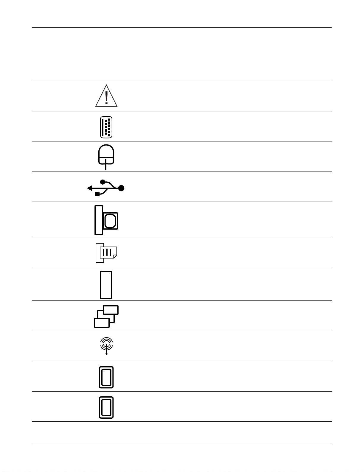
Equipment Symbols
The following symbols appear on the CIC Pro computer.
ATTENTION: Consult accompanying documents before using the equipment.
KEYBOARD ICON: Denotes the keyboard port.
MOUSE ICON: Denotes the mouse port.
USB PORT ICON: Denotes the USB port. This port is NOT used on this system.
Introduction: Equipment Symbols
IOIOI
12
VGA MONITOR ICON: Denotes the VGA monitor port. This port is NOT used on this
system.
PARALLEL (PRINTER) PORT ICON: Denotes the parallel port into which the optional
laser printer is connected.
SERIAL COMMUNICATION (COM) PORT ICON: Denotes the communication (COM)
ports, used for optional service modem and optional PRN 50/PRN 50-M writer.
ETHERNET ICON: Denotes the Ethernet ports used for the Unity Network MC, Unity
Network IX, and RX network connections. The optional RX port is located on an
additional Ethernet card, and is used for connection to telemetry systems, such as
ApexPro.
SPEAKER OUT ICON: Denotes the speaker port connection.
VIDEO 1 ICON: Denotes the primary video port connection.
VIDEO 2 ICON: Denotes the secondary video port connection.
Revision D CIC Pro 1-11
2001099-145
Service Information
Service Requirements
Follow the service requirements listed below.
Refer equipment servicing to GE Medical Systems Information Technologies’
Any unauthorized attempt to repair equipment under warranty voids that
It is the user’s responsibility to report the need for service to GE Medical
Failure on the part of the responsible individual, hospi tal, or inst itut ion using
Regular maintenance, irrespective of usage, is essential to ensure that the
Equipment Identification
Introduction: Service Information
authorized service personnel only.
warranty.
Systems Information Technologies or to one of their authorized agents.
this equipment to implement a satisfactory maintenance schedule may cause
undue equipment failure and possible health hazards.
equipment is always functional when required.
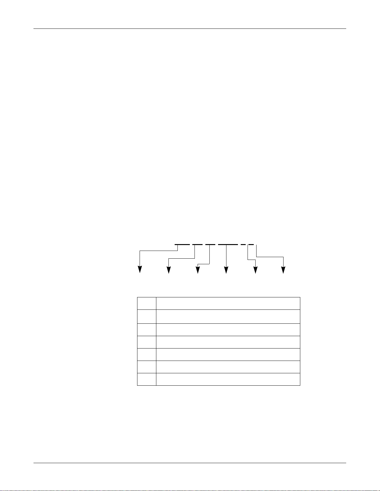
Every GE device has a unique serial number for identification. A sample of the
information found on a serial number label is shown below.
### ## ## #### # #
ABCDEF
Description
A
product code
B year manufactured
C fiscal week manufactured
D production sequence number
E manufacturing site
F miscellaneous characteristic
1. The product code for the CIC Pro is AA1.
1
1-12 CIC Pro Revision D
2001099-145

Older Unit Identification
D 0 XX 0005 G XX
Introduction: Service Information
CIC Pro versions prior to version 4.0.x use the following serial number code
scheme:
Month
Manufactured
A = January
B = February
C = March
D = April
E = May
F = June
G = July
H = August
J = September
K = October
L = November
M = December
Year
Manufactured
0 = 2000
1 = 2001
2 = 2002
3 = 2003
(and so on)
Product Code
Two-character
product descriptor
Product Sequence
Number
Manufacturing
number (of total
units
manufactured)
Division
F = Cardiology
G = Monitoring
Device Characteristics
One or two letters that further
describe the unit, for example:
P = prototype not conforming to
marketing specification
R = refurbished equipment
S = special product documented
under Specials part numbers
U = upgraded unit
Revision D CIC Pro 1-13
2001099-145

For your notes
Introduction: Service Information
1-14 CIC Pro Revision D
2001099-145

2 Equipment Description
Revision D CIC Pro 2-1
2001099-145

For your notes
2-2 CIC Pro Revision D
2001099-145

Equipment Description: Unity Network Description/Connection
Unity Network Description/Connection
Unity Network MC
The Unity Network MC (Mission Critical) network is the network that is used to
connect the server systems to the monitors and to the telemetry cabinets. This
network contains all the waveforms, parameters, alarms and other time-sensitive
data. The CIC Pro server should be connected to the Unity Network MC backbone.
Unity Network IX
The Unity Network IX (Information eXchange) network is used by the network
laser printer and to interconnect the server systems for license sharing. The Unity
Network IX network is also used for the Full Disclosure option.
Unity Network RX
The Unity Network RX (Receiver eXchange) network is the connection to
telemetry systems (e.g. ApexPro).
Network Connections
The following tables specify the physical location of the Unity Network connections
for CIC Pro Nightshade and BCM platforms.
CIC Pro Network Connections
Unity Network
Connection
Unity Network MC Ethernet Port on CPU Ethernet Port marked “MC”
Unity Network IX Ethernet card on back of CPU Ethernet Port marked “IX”
Unity Network RX Optional ethernet card on back
Nightshade Server BCM Server
Optional ethernet card on back
of CPU
of CPU. Port is marked “RX”
Revision D CIC Pro 2-3
2001099-145

Equipment Description: Theory of Operation
Theory of Operation
CIC Pro Functional Description
The CIC Pro application is connected to the Unity Network MC network via
Ethernet to provide real-time patient data and alarms for central nurses’ stations in
hospitals.
The CIC Pro can display real-time waveforms and vital sign data with visual and
audible alarms for up to 16 patients simultaneously. CIC Pro supports both hardwire
and telemetry data.
The software allows the user to select any bed on the Unity Network MC network
and to display an expanded view of that bed’s real-time parameters and waveforms.
This expanded view also allows the user to view and modify settings (within the
care unit) and view other patient data including alarm histories, graphic trends and
tabular trends.
The user can configure the number of patients displayed by the system, and the
number of displayed waveforms per patient. Waveform colors are configurable.
All configuration data is stored, and is restored after a system power cycle or
software restart.
The system runs on the Microsoft Windows NT operating system (version 4.0 SP6
or later).
ApexPro Telemetry System Functional Description
The ApexPro telemetry system is connected to the Unity Network MC network via
Ethernet to provide real-time patient data and alarms for central nurses’ stations in
hospitals and also connects to a telemetry system via the Unity Network RX
network (refer to your specific telemetry system documentation for more
information).
ApexPro telemetry provides clinicians with patient physiological information while
allowing for patient mobility. The physiological parameters monitored include
ECG, non-invasive blood pressure, and SpO
to the CIC Pro for processing and display via Ethernet or the Unity Network MC
network.
. This physiological information is sent
2
How Trends are Calculated
GE Medical Systems Information Technologies systems trend two types of
physiological data: periodic and episodic.
Periodic data is constantly updated. Examples of periodic data include heart rate
(HR) and blood pressure (BP). Episodic data are events that are user or system
generated. Examples of episodic data include temperature (Temp) and non-invasive
blood pressure (NiBP).
Periodic data is sampled every two seconds to get 30 samples per minute. The value
displayed is the median of the 30 samples. Odd-number values are rounded down to
2-4 CIC Pro Revision D
2001099-145

File/Data Handling
Log Files
Equipment Description: Theory of Operation
the nearest even-number. The value is always the median of a one-minute time
frame, regardless of the interval selected. The interval simply defines which trended
data displays (i.e., five minute intervals means the trended data are one-minute
samples spaced five minutes apart, NOT five-minute samples and NOT a median of
the five one-minute samples from that period).
If the calibration of the system clock changes (for example, daylight savings time),
the “time” for periodic data “slides” into the revised time. However, episodic data is
time-stamped and retains its original time.
Log files generated by the CIC Pro application, other associated applications and the
CIC Pro operating system are used during system analysis, problem diagnosis and
troubleshooting. For more information about retrieving log files, refer to the
following:
“Download Logs” on page 7-11.
“View Logs” on page 7-16.
“CIC Pro Log Files” on page 8-6.
“getlog Function” on page 8-7.
“Webmin Connection Errors” on page 8-10.
“Capture All Logs on the CIC Pro” on page 8-19.
“ApexPro Application Log Files” on page 8-27.
RWHAT Packets
Storage
All monitoring devices on the GE Unity Network periodically broadcast information
about themselves in “RWHAT” packets. Among other things, RWHAT packets
contain IP address, port number, name and offered services information about each
device.
All monitoring devices listen for RWHAT packets and maintain a database of
information about other devices on the network. When devices need to
communicate, the appropriate IP address information is obtained from the database
and Unity network protocol messages are created. The operating system services are
used to transmit the message on the network.
For example, when a CIC Pro computer communicates with a telemetry device, the
telemetry device’s IP address is retrieved from the CIC Pro computer’s RWHAT
database. The Unity network messages are created and the operating system sends
the messages to the telemetry device.
The FD Data interface uses the Unity Network IX network to retrieve data from
the database.
Each bed is stored in separate directory, containing one index file and many
record files.
Revision D CIC Pro 2-5
2001099-145

Printing
Full Disclosure
Equipment Description: Theory of Operation
The Report printout is a configurable, long-time-peri od ov erview of waveform
activity. It is activated by pressing the Report Print button on the FD display.
The Strip printout is a quick snapshot of what is currently on the screen. It is
activated by pressing the Print button while the FD tab page is being viewed.
There is a separate FD printer selection from the main laser printer selection on
the setup page. Specifying a printer here does not advertise this CIC Pro as a
print server on (like the main laser selection). It is used exclusively by the local
FD system. A printer must be “Added” to the NT system before it will show up
in the drop-down list.
The CIC Pro Full Disclosure (FD) system stores all waveform and parametric data
from a patient for up to 76 hours. This data can be randomly accessed later in a static
display that looks similar to the real-time display window. To accomplish this every
Unity Network waveform packet (4/sec) and every parameter packet (1 every 2
seconds) are stored to disk on the CIC Pro. In addition one RWHAT packet and one
admit packet are stored every minute to help recreate the patient’s history.
Unlike an alarm history event stored by the bedside, which only stores a 10 second
snap-shot surrounding the event, with Full Disclosure the user can scroll back in
time prior to the event to see what was going on with the patient, leading up to the
event. Each CIC Pro can handle up to 16 patients.
CAUTION
TIME CHANGES AFFECT FULL DISCLOSURE DATA —
When the time is changed on the Unity MC network for spring
and fall Daylight Savings Time (DST) events, CIC Pro Full
Disclosure data will be affected.
When the time is ADVANCED by one hour, the oldest hour
of Full Disclosure data at the end of the FD storage file is
deleted.
When the time is set BACK one hour, the most recent hour of
Full Disclosure data will is replaced with the new hour's Full
Disclosure data.
Before changing the time on the Unity MC network, review the
Full Disclosure information for all patients in the care unit. If
there are events which should be archived, record this information
BEFORE changing the time.
Behaviors/Rules
Installation
Incompatible with CIC Pro v2.X and v3.X.
Certain Unit Defaults are incompatible with CIC Pro v2.X and v3.X.
Installation deletes all FD data if upgraded from v2.X/3.X to v4.X.
2-6 CIC Pro Revision D
2001099-145

Equipment Description: Theory of Operation
Installation clears all FD slots if upgraded from v2.X/3.X to v4.X.
Hardware
Nightshade Platform
FD systems have two hard drives, one dedicated to FD.
Non-FD systems have only one hard drive (FD storage is restricted to 1
hour/patient).
C: ~8GB, F: 18GB (FD).
BCM Platform
Single hard drive, partitioned into two logical.
C: ~8GB, D: ~26GB (FD).
Start-up modes
Auto For All – Automatically detects admitted beds that are not currently being
FD’d anywhere and attempts to start FD on one of the CIC Pros within the unit.
This works regardless of whether the bed was admitted directly at the bedside or
the CIC Pro. FD cannot be stopped on a particular bed until the bed is
discharged.
Auto If Listed – Same as Auto For All but only if the bed in question is entered
into the list on the FD Unit Defaults setup screen. All other beds are not Full
Disclosed
Manual Mode – Beds are NOT automatically full disclosed upon admission.
User can manually start and stop FD for a particular bed by using a button
located on the Full Disclosure tab sheet. All FD data is deleted when Full
Disclosure is stopped for a bed.
.
Licensing
Control
Support for up to 16 patients per CIC Pro.
Stores 76 hours of data per patient, unless disk drive is less than 10GB
(considered a non-FD machine. Nightshade servers only), then only 1 hour of
data is stored.
Stores 76 hours of data regardless of license type. Licensing controls amount of
data that is viewable.
Unit Licensing Mode sets which type of licen se is requested. Supported types:
None (1 hour), 24, 48, 72 hours.
Failure to obtain a license results in that bed not being FD’d (0 hours).
Once a license is successfully obtained, if the license server is removed, access
is restricted to 1 hour, until the server is returned.
Licensing information is stored with data, so restrictions follow data regardless
of where it is viewed, even if viewed in a different unit with a different Unit
License Mode.
CIC Pro Master and Full Disclosure
NOTE
There is only one “master” CIC Pro per unit (with respect to FD). The CIC Pro
with the lowest IP address is the master.
Revision D CIC Pro 2-7
2001099-145

Equipment Description: Theory of Operation
The CIC Pro master wakes up every minute to perform the following activities:
Detects admitted (but not FD’d) beds within the unit for Auto modes.
Assigns beds (to be FD’d) to CIC Pros within the unit .
Applies Multi-FD and Twin-Bed Rules.
Uses the FDSvr process to find the "FULL DISCLO" service, identifying CIC
Pros with FD ability. The "FULL DISCLO" service is used by the CIC Pro
master while searching for other CIC Pros to query, control & assign beds.
NOTE
The CIC Pro master checks the versions of the other CIC Pros before trying
to identifying CIC Pros with FD ability. Versions earlier than 2.5 are
ignored.
Uses the LocateFD service (provided by FDSvr) to guarantee that the right CIC
Pro is contacted if retrieving data while a multi-FD condition is occurring.
NOTE
A CIC Pro will NOT act as master during first minute after start-up. Instead,
the latest data is first collected from the other CIC Pros on the network, and this
data determines which CIC Pro becomes master. Multiple masters on a network
might occur, but only briefly--this will self-correct within a couple of minutes.
Minute Rule/Offline Storage Setting
(see “Offline Storage” on page 3-36)
The Offline Storage Setting determines the length of time the CIC Pro will maintain
FD data for a bed from which it has stopped receiving data (a NO COMM
condition).
If the NO COMM condition ends WITHIN the Offline Storage setting time
frame, FD for the bed continues.
If a NO COMM condition exceeds the Offline Storage Setting time frame, all
data for the bed is deleted. If (while in Auto mode) the bed comes back online
(the NO COMM condition ends) after this point, the bed is reassigned as a new
and different bed.
When FD starts up on a CIC Pro, it determines when data was last received
from the assigned beds.
If the latest data for a bed:
IS NOT older than the Offline Storage Setting, then FD data collection
continues for the bed.
IS older than the Offline Storage Setting, existing data associated with the
bed is deleted, and a NEW data collection is started for the bed.
Multi-FD Rule
If multiple CIC Pros are running in a unit, the Multi-FD Rule allows switching of
FD data collection from one CIC Pro to another if a CIC Pro goes offline (reboot,
shutdown, etc.).
The following examples describe how the Multi-FD Rule works when using 2 CIC
Pros (CICA and CICB).
2-8 CIC Pro Revision D
2001099-145

Equipment Description: Theory of Operation
NOTE
In the examples, start up mode is “Auto”, and only one bed (BED1) is used.
Example 1:
1. CICA goes offline and stops FD'ing BED1. This causes CICB to begin FD'ing
BED1.
NOTE
The master CIC Pro detects CICA going offline, and switches FD over to
CICB, within a minute of the offline event occurring.
2. CICA comes back online within the Offline Storage Setting time frame, and
continues FD'ing BED1 again. At this point, CICA and CICB are BOTH FD'ing
BED1.
3. The Multi-FD Rule does not allow more than one CIC Pro to FD the same bed
at the same time--only the data that goes the farthest back in time (CICA) is
kept. Because of this, CICA continues FD'ing BED1, and CICB stops.
Example 2:
1. CICA goes offline and stops FD'ing BED1. This causes CICB to begin FD'ing
BED1.
NOTE
The master CIC Pro detects CICA going offline, and switches FD over to
CICB, within a minute of the offline event.
2. CICA comes back online after exceeding the Offline Storage Setting time
frame. Because of this, existing BED1 data is deleted from CICA, and NEW
BED1 data collection begins on CICA. At this point, CICA and CICB are
BOTH FD'ing BED1.
3. The Multi-FD Rule does not allow more than one CIC Pro to FD the same bed
at the same time--only the data that goes the farthest back in time (CICB) is
kept. Because of this, CICB continues FD'ing BED1, and CICA stops.
NOTE
At every wake-up cycle (1 minute interval), the CIC Pro master scans all CIC
Pros within the unit to determine if more than one CIC Pro is FD’ing the same
bed (this can happen as part of normal operation). If the master detects this
condition, all CIC Pros are instructed to stop FD’ing the bed except for the one
CIC Pro with the oldest data for the bed.
Revision D CIC Pro 2-9
2001099-145

Equipment Description: Theory of Operation
Combo mode (Twin-Bed Rule)
In combo mode:
1. Two beds are on the network: one is a hardwired bed, and the other is telemetry
bed. Both beds share the same name (e.g. BED), but '*' is added to the name of
the telemetry bed name (e.g. BED and BED*). Both beds represent the same
patient. NOTE: If NOT in combo mode, these two beds would be treated as
distinct and separate.
2. Only the oldest bed data is kept. Data for the other bed is deleted.
3. No matter which data is kept, FD continues, and the data is stored under the bed
name, but without the '*'.
4. Combo mode is stopped (breaking combo) by discharging either bed. If this
happens, FD continues on the UNDISCHARGED bed, and the data is stored
under the UNDISCHARGED bed name.
NOTE
If the hardwired bed is discharged, '*' would again be included in the
name.
Combo Mode Example 1:
a. A hardwired bed BED is admitted and is FD'ed.
b. A telemetry bed BED* is admitted and is FD'ed. Two separate FD data
stores exist, one for each bed (could be on different CIC Pros).
c. The two beds are put into combo mode. When this happens, BED data is
kept because it is older than BED* data, and BED* data is deleted. FD
continues, and the data is stored under the name BED.
d. Combo is broken by discharging BED*. FD continues, with the data is still
stored under the name BED.
Combo Mode Example 2:
a. A hardwired bed BED is admitted and is FD'ed.
b. A telemetry bed BED* is admitted and is FD'ed. Two separate FD data
stores exist, one for each bed (could be on different CIC Pros).
2-10 CIC Pro Revision D
2001099-145

Equipment Description: Theory of Operation
c. The two beds are put into combo mode. When this happens, BED data is
kept because it is older than BED* data, and BED* data is deleted. FD
continues, and the data is stored under the name BED.
d. Combo is broken by discharging BED. FD continues, with the data is NOW
stored under the name BED*.
Combo Mode Example 3:
a. A telemetry bed BED* is admitted and is FD'ed.
b. A hardwire bed BED is admitted and is FD'ed. Two separate FD data stores
exist, one for each bed (could be on different CIC Pros).
c. The two beds are put into combo mode. When this happens, BED* data is
kept because it is older than BED data, and BED data is deleted. FD
continues, and the data is stored under the name BED*.
d. Combo is broken by discharging BED*. FD continues, with the data is still
stored under the name BED.
Combo Mode Example 4:
a. A telemetry bed BED* is admitted and is FD'ed.
b. A hardwired bed BED is admitted and is FD'ed. Two separate FD data
stores exist, one for each bed (could be on different CIC Pros).
c. The two beds are put into combo mode. When this happens, BED* data is
kept because it is older than BED data, and BED data is deleted. FD
continues, and the data is stored under the name BED.
d. Combo is broken by discharging BED. FD continues, with the data is NOW
stored under the name BED*.
Bed Name/IP Address Changes
The CIC Pro tracks FD data for individual beds using a combination of bed name
and IP address.
If a bed name changes during FD, information within the data reflects the new name
at the point the name change occurred.
If a bed IP address changes during FD, but the name does not, it is interpreted as a
new and different bed, and a new FD data store is created and utilized for the new
bed.
Revision D CIC Pro 2-11
2001099-145

Unit Boundary
Equipment Description: Theory of Operation
If a bed goes offline, and another bed with the same name but a different IP address
comes online, it is interpreted as a new and different bed and a FD data store is
created and utilized for it. However, the following conditions apply:
If the bed that went offline (with the original IP address) comes back online
within the Offline Storage Setting timeframe, the two beds continue to be
treated as separate, since the different IP addresses positively identify them as
distinct and separate.
If the bed that went offline (with the original IP address) DOES NOT come
back online within the Offline Storage Setting timeframe, the bed with the new
IP address is interpreted as a REPLACEMENT for the bed with the original IP
address. In this case, the FD data for the bed with the original IP address is
deleted, and FD continues, storing data for the bed with the new IP address
ONLY.
Each unit operates independently with respect to Full Disclosure. The only
interaction is when displaying data across units.
License Mode – All beds within a unit will have access to the same amount of
data storage (based on time) unless there is a failure to get a license (0 hours).
Can be different across different units (i.e. UnitA-72hours, UnitBNone)(1hour).
Start-up Mode – Same start-up rules applied to all beds within a unit.
Default – Same FD defaults used on all CIC Pros within a unit.
Master – One per unit.
Acquisition/Storage – The master will only assign beds within the unit to CIC
Pros within the unit. At no time will data for a bed be stored on a CIC Pro in a
different unit.
Bed Unit Changes – If a bed changes its unit name while bein g FD’d, all data
for the bed is deleted. The unit to which the bed moved is responsible for
dealing with the bed.
CIC Pro Unit Changes – If a CIC Pro changes its unit name while FD’ing beds,
all data for all beds being FD’d by that CIC Pro is deleted. The unit to which the
beds belonged is responsible for dealing with those beds.
2-12 CIC Pro Revision D
2001099-145

Equipment Description: CIC Pro Service Logons
CIC Pro Service Logons
The following procedures are for entering various levels of CIC Pro software. Each
logon provides a different level of accessibility. Follow these steps to logon as
appropriate.
CAUTION
The bed displayed at this CIC Pro is unmonitored while the CIC
Pro is shut down. Any beds admitted on this CIC Pro PC display
“NO COMM” if displayed at other centrals and are not monitored.
To shut down the CIC Pro application and log on as a different user:
1. Select Setup CIC.
2. Select the Service Password tab.
3. Type mms_com as the Password.
4. In the command box that opens, type stop and then press Enter.
Full-Access Logons
Site Administrator Logon
5. Click on Start then select Shut Down and Close All Pro grams And Log On As
Different User.
6. Hold down Shift and select Yes.
Continue holding until prompted for the password.
7. Choose from the following logons and continue as instructed.
The following logons are “full-access” administrative accounts used to update
software and make changes to the operating system configuration.
The two accounts are separate but similar: one for the site administrator, the other
for field service personnel.
To logon as site administrator, complete the following when prompted for logon:
User name: type administrator and press Tab.
Password: type admin1,3,5,7 and press Enter.
CIC Pro Administrator Logon
To logon as CIC Pro System Administrator, complete the following when prompted
for logon:
User name: type cicadm and press Tab.
Password: type cicadm1,3,5,7 and press Enter.
Revision D CIC Pro 2-13
2001099-145

Equipment Description: CIC Pro Service Logons
Limited-Access Logon
Run-Time Logon
The following logon is a “limited-access” user account and should be used to review
logs or restart CIC Pro.
For CIC Pro Limited Access logon, complete the following when prompted for
logon:
User name: type cicuser and press Tab.
Password: type cicuser1,3,5,7 and press Enter.
The following logon is a “run time” user account and should be used to restart CIC
Pro to run in the normal user interface mode.
User name: type CIC and press Tab.
Password: type cic and press Enter.
Service Mode Logon
Password: mms_cic
2-14 CIC Pro Revision D
2001099-145

Equipment Description: CIC Pro and ApexPro Host Components
CIC Pro and ApexPro Host Components
Hardware
The system uses a PC tower with the choice of a 15-inch, 17-inch, or 20-inch color
computer display. The entire system is assembled with the display choice, loaded
with software, and then shipped as a complete unit ready for setup and use.
To run the system, the PC tower comes with the following internal components:
Nightshade Server (CIC Pro)
The Nightshade server includes the following hardware:
SCSI internal hard disk drive
CD-ROM drive
High density floppy disk dri ve
Integral video controller (one)
256kB DRAM video memory module
Integral audio controller (one)
Ethernet PCI (PC interface) plug-in circuit board (one)
Dual CPU
1280 x 1024 x 65536 video card
16-bit sound card
2 external speakers
128 MB RAM
BCM Server (CIC Pro)
The BCM server includes the following hardware:
SCSI internal hard disk drive
CD-ROM drive
High density floppy disk dri ve
Integral video controller (one)
256kB DRAM video memory module
Integral audio controller (one)
Ethernet PCI (PC interface) plug-in circuit board (one)
Single or Dual CPU
2560 x 1024 x 65536 dual video card (only with product code AA1)
16-bit sound card
2 external speakers
128 MB RAM
Revision D CIC Pro 2-15
2001099-145

Equipment Description: CIC Pro and ApexPro Host Components
CIC Pro with ApexPro Telemetry System Host
The ApexPro telemetry system host includes the following hardware:
SCSI internal hard disk drive
CD-ROM drive
High density floppy disk dri ve
Integral video controller (one)
256kB DRAM video memory module
Integral audio controller (one)
Ethernet PCI (PC interface) plug-in circuit board (one)
Dual CPU
2560 x 1024 x 65536 dual video card (only with product code AA1)
16-bit sound card
2 external speakers
256 MB RAM
2-16 CIC Pro Revision D
2001099-145

Equipment Description: CIC Pro IP Address Information
CIC Pro IP Address Information
Display All IP Addresses
To display all the IP addresses on the Unity Network IS server subnets:
1. Click on the Setup CIC button.
2. Click on the Service Password tab.
3. Position the cursor in the Password field and type mms_com. Click on Apply.
4. Type ipconfig<space>/all and press Enter. The IP Configuration information
appears.
The following example is from a BCM server machine:
Ethernet adapter E100B4:
Description. . . . . . . . : Intel(R) PRO Adapter
Physical Address. . . . . . : 00-10-F3-03-02-7F
DHCP Enabled. . . . . . . . : No
IP Address. . . . . . . . . : 121.64.68.1 (IX)
Subnet Mask . . . . . . . . : 255.0.0.0
Default Gateway . . . . . . :
Ethernet adapter E100B3:
Description . . . . . . . . : Intel(R) PRO Adapter
Physical Address. . . . . . : 00-10-F3-03-02-80
DHCP Enabled. . . . . . . . : No
IP Address. . . . . . . . . : 126.64.68.2 (ApexPro Host)
Subnet Mask . . . . . . . . : 255.0.0.0
IP Address. . . . . . . . . : 126.64.68.1 (MC)
Subnet Mask . . . . . . . . : 255.0.0.0
Default Gateway . . . . . . :
Ethernet adapter E100B2:
Description . . . . . . . . : Intel(R) PRO Adapter
Physical Address. . . . . . : 00-50-DA-15-75-3D
DHCP Enabled. . . . . . . . : No
IP Address. . . . . . . . . : 119.1.1.2 (RX)
Subnet Mask . . . . . . . . : 255.0.0.0
Default Gateway . . . . . . :
5. Close the Command Prompt window.
6. Close the CIC Setup window.
NOTE
See “IP Address Configuration” on page 3-44 for IP Address configuration
procedure information.
Revision D CIC Pro 2-17
2001099-145

Equipment Description: CIC Pro IP Address Information
CIC Pro Network Cards
The following table displays the CIC Pro Adapter selections for the CIC Pro
network cards.
CIC Pro Adaptor Selections
Unity Network/
Application
Unity Network MC for
CIC Pro & ApexPro
Host
Unity Network IX [2] 3Com Fast EtherLink XL NIC
Unity RX Network for
telemetry system (e.g.
ApexPro)
NOTE
These adapters are listed in the Windows Internet Protocol (TCP/IP) Properties
window.
Adaptor for Nightshade Server Adaptor for BCM Server
[1] Intel EtherExpress PRO
Adapter
(3C905B-TX)
[3] 3Com Fast EtherLink XL NIC
(3C905B-TX)
[3] Intel (R) PRO/100+
Management Adapter
[4] Intel (R) PRO/100+
Management Adapter
[2] Intel (R) PRO/100 S
Desktop Adapter
2-18 CIC Pro Revision D
2001099-145

Equipment Description: CIC Pro Telemetry Tower Option
CIC Pro Telemetry Tower Option
The TELEMETRY TOWER option includes several selections that allow new
software to be loaded into a CD Telemetry®-LANTM cabinet assembly (or
subsystem) through a disk drive. The software up-load process for the telemetry
tower is controlled entirely through the CIC Pro system.
To upload software into the Telemetry Tower, refer to the ApexPro software
upgrade instructions PN2001989-188.
WARNING
Perform software uploads according to the update instructions that
accompany the software. Improper use of this option may result in
loss of patient monitoring or patient data. Do NOT upload
software unless instructed to do so by qualified service personnel
and only after the telemetry system is properly prepared.
As part of procedure you have to reboot the tower to initiate new
tower.
Make sure you notify the responsible personnel for the admitted
patients (monitored by the CD Telemetry-LAN cabinet (or
subsystem) that is rebooted) that the cabinet will be rebooted and
they will lose patient monitoring for a few minutes.
WARNING
During the reboot period monitoring functions are lost. The
buttons for the "lost" patients change on the central stations to
show ADMIT. This may lead some monitoring system users to get
the "lost" patients back by readmitting them. Instruct all personnel
NOT to admit any of the "lost" patients during reboot. Once the
cabinet finishes rebooting the "lost" patients return automatically.
Note that when you activate new software, all patient historie s and
trends are lost.
Revision D CIC Pro 2-19
2001099-145

Equipment Description: CIC Pro Full Disclosure License Management Setup
CIC Pro Full Disclosure License Management Setup
BCM Server
Each CIC Pro with version 4.x software comes with the ability to store 16 beds of
Full Disclosure (FD) data for one hour without a license. A CIC Pro with the Full
Disclosure option and version 4.x software has the ability to store up to16 beds for
72 hours with the appropriate licenses and license settings.
When operating two CIC Pro servers within the same “care unit” where one has the
Full Disclosure option and the other does not, it is necessary to turn Full Disclosure
OFF on the CIC Pro without the Full Disclosure option to prevent a conflict with the
two different storage capacities of the CIC Pro units.
Server Without Full Disclosure
A Nightshade/Omnitech platform may require a hardware modification to support
anything greater than 1 hour Full Disclosure. However, for those Nightshade/
Omnitech CIC Pro that do not have a F drive and have purchased Full Disclosure
licenses within the care unit, you must perform the following steps to disable Fu ll
Disclosure on that CIC Pro.
1. Select Setup CIC and click on the Service Password tab.
2. Type mms_com and press the Enter key. The CIC command window displays.
3. Type fdcmd -n OFF and press the Enter key. Beds that were full disclosed on
this PC are now deleted.
4. Type stop.
5. Select Start > Shutdown > Close all programs and log on as a differen t user .
Allow the CIC Pro to boot up in CIC mode. Wait for at least 3 to 4 minutes.
6. Check the other CIC Pro servers on the unit to ensure the full disclosure
function is still enabled somewhere on the unit
a. Select Setup CIC and click on the Service Password tab.
b. Type mms_com and press the Enter key. The CIC command window
displays.
c. Type fdcmd -lu and verify beds are now full disclosed on another CIC Pro
that support >1-hour Full Disclosure storage.
d. Type exit and close all open windows.
NOTE
The above procedure may be followed on any CIC Pro (BCM, Nightshade or
Omnitech hardware platform).
2-20 CIC Pro Revision D
2001099-145

Equipment Description: ApexPro PTSCONFIG Utility
ApexPro PTSCONFIG Utility
If the CIC Pro server includes the ApexPro option, the PTSCONFIG utility is a
console application that allows you to configure the ApexPro application.
NOTE
Not all of the commands in the following table may apply to your telemetry
system. If applicable, see the separate service or configuration documentation
for your specific ApexPro installation for more information about using these
commands with your specific telemetry system.
display Commands
The commands listed below display ApexPro application information.
Command displays...
help list of available commands
display Commands
display<Space>tower ApexPro tower’s full name “UNIT|NAME”
display<Space>software software versions for all running software (main, rack,
etc.)
display<Space>build date/time the software was built
display<Space>patient patient information: TTX, tower, and receiver numbers
display<Space>patreceiver information about the patient’ receiver and transmitter
display<Space>IP IP address used by the ApexPro application to talk to
the Unity Network
display<Space>rack IP address used by the ApexPro application to talk to
the telemetry system
display<Space>receiver receiver/unit assignments for this ApexPro tower
display<Space>ttx network-wide in-use TTX list (from the TTX master list)
display<Space>unitlist network-wide unit/receiver list (from the TTX master
list)
Revision D CIC Pro 2-21
2001099-145

modify Command
listwhat Command
Equipment Description: ApexPro PTSCONFIG Utility
The commands listed below permit modifications to the ApexPro application.
modify Command
Command allows modification to...
modify<Space>unit ApexPro tower’s unit name
modify<Space>tower ApexPro tower’s device name
modify<Space>ip IP address used by the ApexPro application to talk to the
Unity Network
modify<Space>rack IP address used by the ApexPro application to talk to the
telemetry system
modify<Space>receiver receiver/unit assignments for this ApexPro tower
Other Commands
For information on using the listwhat command, refer to “List Network” on page 8-
24.
The table below lists other ApexPro software commands.
Other Commands
Command function...
admit admits a patient on this ApexPro tower (“admit” shows usage)
discharge discharges a patient on this ApexPro tower (“discharge” shows
usage)
dload downloads rack software (“dload” shows usage)
resetrack immediately (with no confirmation) resets all racks connected to
the tower
blink
patient
rack
receiver
stop
blinks rack LED(s) according to:
entered patient name (UNIT|BED)
entered ApexPro tower IP address
entered ApexPro tower IP address and receiver number
stop any blinking
boot reboots the PC (“DDMM” password required: confirmation is also
requested)
shutdown restarts ApexPro application (“DDMM” password required:
confirmation is also requested)
2-22 CIC Pro Revision D
2001099-145

Equipment Description: ApexPro PTSCONFIG Utility
Other Commands
Command function...
statistics
waveform
wavereset
histogram
histreset
displays ApexPro software performance statistics:
waveform data latency timing through ApexPro software
reset waveform data latency timing counters
waveform data timing through ApexPro software
reset waveform data timing counters
storeecg stores a file containing raw patient ECG sample data
Revision D CIC Pro 2-23
2001099-145

For your notes
Equipment Description: ApexPro PTSCONFIG Utility
2-24 CIC Pro Revision D
2001099-145

3 Installation &
Configuration
Revision D CIC Pro 3-1
2001099-145

For your notes
3-2 CIC Pro Revision D
2001099-145

Installation & Configuration: Pre-Installation Requirements
Pre-Installation Requirements
Read and fully understand the pre-installation requirements. Verify all requirements
are met before attempting installation of the CIC Pro system.
Site Requirements
The computer tower is capable of producing heat and must be physically located to
allow the heat load to be adequately dissipated.
WARNING
SERVER LOCATION — The computer server is UL 60950\IEC
60950 certified equipment which may not meet the leakage
requirements of patient care area equipment. This equipment must
not be located in the patient vicinity as a shock hazard may exist,
unless the medical electrical system standard, IEC 60601-1-1 is
followed.
Failure to adequately ventilate the computer tower may cause
equipment failure or improper operating conditions which may
endanger the patients being monitored.
Environmental Limits
CAUTION
Do not locate the computer tower or display in an enclosed area
that may restrict dissipation of the heat generated by the
components. Any air flow restrictions may cause a rise in internal
temperature which may result in equipment failure. The computer
tower uses an internal forced air cooling system, but most displays
do not.
The user must determine the heat dissipation requirements of the
selected display and design a ventilation system accordingly.
The server operates reliably within normal office environmental limits. Select a site
that meets these criteria:
Clean and relatively free of excess dust.
Well ventilated and away from sources of heat.
Away from sources of vibration or physical shock.
Revision D CIC Pro 3-3
2001099-145

Installation & Configuration: Pre-Installation Requirements
Electromagnetic Fields and Electrical Noise
The server should be isolated from strong electromagnetic fields and electrical noise
produced by electrical devices such as elevators, copy machines, air conditioners,
large fans, large electric motors, radio and TV transmitters, and high frequency
security devices.
Clearance and Airflow
The site should provide sufficient clearance behind and around the server to ensure
proper cooling and airflow. Keep ventilating openings on the server free of
obstructions.
Allow about 31 centimeters (12.2 inches) of clearance in back of the server, 60
centimeters (23.6 inches) on the sides, and 22 centimeters (9 inches) in front.
Access Space
Plan access space for server maintenance. Make sure there is convenient access to
disconnect the AC power cord from the wall outlet or from the back of the server,
because disconnecting the cord is the only way to remove AC power from the server
before doing maintenance or upgrade procedures. Pressing the DC push-button on/
off switch on the front panel does NOT remove server AC power.
Physical Specifications
Physical Specifications
Nightshade Server BCM Server
Height 49.02 cm (19.3 in) 42.17 cm (16.6 inches)
Depth 44.96 cm (17.7 in) 48.0 cm (18.9 inches)
Width 21.08 cm (8.3 in) 20.0 cm (7.9 inches)
Weight
17.1 kg (38 lbs.) minimum
22.9 kg (51 lbs.) maximum
11.3 kg (25 lbs.) minimum
13.1 kg (29 lbs.) maximum
3-4 CIC Pro Revision D
2001099-145

Installation & Configuration: Pre-Installation Requirements
Power Requirements
Duplex Wall Receptacles
CAUTION
Loss of power to the computer tower results in loss of patient
monitoring capabilities to the system, and to any remote display
monitors connected via hardwire or modem.
Two properly grounded duplex wall receptacles should be provided for each system.
Additional receptacles may be required to accommodate peripheral equipment
connected to the system. The wall receptacles must be installed in an approved
junction box. Use only three-prong, polarized, hospital-grade wall receptacles to
accept the three-prong polarized plug on the computer equipment.
Un-Interruptible Power Supply (UPS)
GE Medical Systems Information Technologies recommends the use of an uninterruptible power supply (UPS) with the system. If a UPS is NOT used, a power
outage could result in an improper shut down of the system and cause a lengthy disk
scan procedure when the unit reboots. You could also lose data in the event of a
power outage if you do not use a UPS.
CAUTION
Connect the UPS to the PC CPU(s) and display(s) only. Do NOT
connect printers or other devices to a UPS. Other devices my
shorten estimated run times. If power is not restarted in time the
unit shuts down and patients will not be monitored.
Follow the UPS manufacturer’s recommendations for installation.
UPS Runtime Estimates and Options
CAUTION
Connect the UPS to the PC CPU(s) and display(s) only. Do NOT
connect printers or other devices to a UPS. Other devices may
shorten estimated run times. If power is not restarted in time the
unit shuts down and patients will not be monitored.
Runtimes are expressed in hours:minutes. Typical runtimes based on fully charged,
new batteries operating under typical load conditions. Runtimes are affected by:
Battery age,
Ambient temperature,
Site specific UPS usage patterns, and
Load characteristics.
Revision D CIC Pro 3-5
2001099-145

Installation & Configuration: Pre-Installation Requirements
Your actual run time may be different.
UPS Runtimes (Hours:Minutes)
Percent of Capacity ON400 ON600 ON900
10 1:33 1:45 1:59
20 0:43 0:52 0:58
30 0:27 0:34 0:37
40 0:19 0:25 0:27
50 0:15 0:20 0:21
60 0:12 0:17 0:17
70 0:10 0:14 0:14
80 0:09 0:13 0:12
90 0:08 0:11 0:10
100 0:07 0:10 0:09
UPS Options
Type Description Limits
UPS4=A Oneac ON400XRA-HOE Domestic
120V 400VA, UL 1778, CSA 22.2
UPS6=A Oneac ON600A-HO Domestic 120V
600VA, UL 1778, CSA 22.2
Will power one server and 21-inch
display for approximately 10min.
Will power one server and 21-inch
display for approximately 30min.
Will power two servers and two 21-inch
displays for approximately 10min.
UPS4=Y Oneac ON4001-SN Intl. 220-240V
400VA, UL 1778, CSA 22.2
UPS6=Y Oneac ON6001-SN Intl. 220-240V
600VA, UL 1778, CSA 22.2
Will power 1 server and 21-inch display
for approximately 10min.
Will power one server and 21-inch
display for approximately 30min.
Will power two servers and two 21-inch
displays for approximately 10min.
UPS4=C Oneac ON900J-SN JAPAN 120V
50/60hZ 900VA, UL1778, CSA 22.2
Will power one server and 21-inch
display for a minimum of 30min.
Will power two servers and two 21-inch
displays for a minimum of 10min.
3-6 CIC Pro Revision D
2001099-145

Installation & Configuration: Pre-Installation Requirements
Equipment Grounding
WARNING
SHOCK HAZARD — The computer tower and all peripheral
equipment must be adequately grounded or a shock hazard may
exist.
The grounding pin of all wall receptacles and all exposed metal parts (beds,
radiators, water pipes, etc.) in any patient area should be electrically connected
together. This common ground point should be connected to the nearest
equipotential ground through a bonded grounding system, or with a 10 AW G
stranded copper grounding cable.
The equipotential ground point should be as close to earth ground potential as
possible. If a bonded grounding system is not available, the ground pin of each wall
receptacle must be individually connected to a central grounding point. Do NOT
jumper from ground pin-to-ground pin of the receptacles.
The grounding system must not carry current, such as a grounded neutral, since the
current flow will produce potential differences along the ground path. These
potential differences are a shock hazard source for equipment users and patients.
Do NOT use conduit as a ground conductor. Plastic (PVC) piping or fittings used in
the conduit runs can break the electrical connection to ground, resulting in potential
shock hazards.
The electrical grounding system should be connected on an earth ground. If this is
not possible, then a good ground reference such as a metal water pipe or an
electrically-conductive building component should be used. IT IS MORE
IMPORTANT THAT ALL GROUNDED OBJECTS IN THE PATIENT AREA
ARE AT THE SAME GROUND POTENTIAL RATHER THAN AT EARTH
GROUND POTENTIAL.
Revision D CIC Pro 3-7
2001099-145

Installation & Configuration: CIC Pro Installation
CIC Pro Installation
WARNINGS
CIC Pro V4.x is NOT in-unit compatible with prior versions of
CIC Pro or any version of Centralscope. Sharing of the same care
unit name across central stations having incompatible software
versions can result in lost or corrupted alarm defaults data and loss
of audible alarms.
(CIC Pro v4.0.7 Only) Care units running more than one CIC Pro
must complete the procedure “Care Units with Multiple CIC Pros
Telemetry Defaults Upgrade” on page 3-53 after performing the
upgrade procedure. Failure to perform this procedure creates a inunit incompatibility situation which can result in lost or corrupted
telemetry alarm defaults data and loss of audible alarms.
Do not exceed a maximum of 15 CIC Pros in a single logical care
unit. Both hardwire and telemetry beds are limited in the number
of remote view connections that can be supported. Attempting
simultaneous displays of a patient monitor (bedside or telemetry)
at too many CIC Pros may cause lost or intermittent
communication between CIC Pros and the patient monitor. This is
evidenced by NO COMM or intermittent communication
conditions for the beds. The maximum CIC Pros viewing a patient
monitor can vary depending on patient monitor capabilities and
network design.
WARNINGS
Only external devices specifically designed to be connected to the
PC tower, or approved by GE Medical Systems Information
Technologies for use with this system, should be connected, as
specified in this manual or as otherwise specified by the
manufacturer.
A shock hazard may exist if external devices are connected other
than as described in this manual, or as directed by the
manufacturer.
External equipment must be connected to the CIC Pro only by
qualified biomedical engineering personnel.
WARNING
When using keyboard/video/mouse (KVM) switching devices
with the CIC Pro, only the keyboard and mouse should be
switched through the KVM. The video for each CIC Pro should be
displayed on its own monitor. Failure to do so may result in
delayed recognition of alarm events.
3-8 CIC Pro Revision D
2001099-145

Pre-Installation Check
Installation & Configuration: CIC Pro Installation
CAUTION
All external cabling used with the server systems must be routed
so as not to interfere with access or operation of the system.
All cabling must be installed to protect against tripping and
accidental disconnection of the cables.
Do NOT apply power until all equipment is installed and ready for
use.
CAUTION
This assembly is static sensitive and should be handled using
precautions to prevent electrostatic discharge damage.
1. Remove all equipment, including all peripheral devices, from the shipping
cartons and inspect for damage.
2. Identify all required cables and prepare them for installation.
3. Verify AC power is available for the computer tower and all peripheral
equipment. Make sure the power supplies are installed, tested, and ready for use
in accordance with “Pre-Installation Requirements” on page 3-3. This includes
testing for proper grounding of the power source.
4. Verify the desired physical location for the computer tower is in accordance
with “Site Requirements” on page 3-3. Place the computer at the selected site.
Revision D CIC Pro 3-9
2001099-145

Installation & Configuration: CIC Pro Installation
Connect Keyboard and Mouse
Connect the keyboard and mouse cables to the back of the PC tower.
NIGHTSHADE SERVER
Mouse
MOUSE
PORT
Cable
Keyboard
Cable
SERIAL
COM1
SERIAL
PORT
ETHERNET
PORT
KEYBOARD
PORT
COM2
PORT
PARALLEL
PORT
Keyboard
KEYBOARD
PORT
COM1
SERIAL
PORT
BCM SERVER
Cable
Mouse
Cable
MOUSE
PORT
PARALLEL
PORT
COM2
SERIAL
PORT
ETHERNET
PORTS
3-10 CIC Pro Revision D
2001099-145

Install the Speakers
Installation & Configuration: CIC Pro Installation
NIGHTSHADE SERVER
SOUND
CARD
SPK OUT
Speaker
Cable
SPK OUT
BCM SERVER
Speaker
SOUND
CARDS
Speaker
Cable
1. Identify the speaker output jack on the sound card at the back of the PC tower.
The speaker output jack is labeled SPK OUT or marked with an icon.
NOTE
The speaker output jack is always the left-most jack.
Strain Relief Bracket
Output Icons
2. A bracket is used as a strain relief and to hold the speaker connector in place.
Loosen the screw on the bracket just enough to insert the speaker connector
through the bracket hole and into the speaker output jack. Make sure the
connector is seated properly, then tighten the strain relief bracket screw to hold
it in place.
WARNINGS
Accidental disconnect of the speaker cables will result in loss of
audible patient alarms at the CIC Pro monitoring location. Make
sure the speaker connections at the PC tower and the speakers are
properly secured with the provided strain relief brackets.
CIC Pro audible alarms will not sound for patients with bedside
monitoring devices configured to “Operating Room” mode.
Revision D CIC Pro 3-11
2001099-145

Installation & Configuration: CIC Pro Installation
Install the Power Cord
Cable Clamp
AC Power Cord
Case Screw
REAR VIEW OF TOWER
1. Remove the upper right case screw from the rear of the chassis.
2. Plug the AC power cord into the PC tower.
3. Install the provided cable clamp around the AC power cord approximately 15
cm (6 in.) from the server connection end.
4. Secure the cable clamp to the chassis with the case screw installed in the upper
right case hole. Tighten the screw.
3-12 CIC Pro Revision D
2001099-145

Installation & Configuration: CIC Pro Installation
Connect the Video Display Monitor
Connecting Monitors to a Dual Video Card
CIC Pro version 4.0.x and later support dual monitor configurations. Only one
monitor (primary) can be used for patient waveform/parameter display. The
secondary monitor can be used for CIC Pro webmin or other GE applications (such
as Stat View, MUSE, etc.) and other hospital trusted applications and sites.
NOTE
Do not connect to the video connection on the mother board (near the parallel
port connector).
Connect the monitor cables to the two video card connections at the back of the
server.
Secondary
Monitor Port
2
Primary
Monitor Port
1
DUAL VIDEO
CARD
Monitor
Cables
NOTE
The right video port is for the primary monitor. This port is used for the main
CIC multiple patient viewer window, and when only one monitor is used with
the server.
When upgrading CIC Pro Version 3.1 or earlier systems to dual monitors, refer to
“Dual Monitor Installation and Configuration” on page 3-49 to install the drivers
and configure the video display software settings to support the dual video card.
Revision D CIC Pro 3-13
2001099-145

Installation & Configuration: CIC Pro Installation
Connecting a Monitor to a Single Display Card
VIDEO
CARD
Monitor
Cable
NOTE
Do not connect to the video connection on the mother board (near the parallel
port connector).
Connect the video display monitor cable to the video card connection at the back of
the server.
NOTE: These connectors are not used
and may not exist on some units.
Connect the Digital Writer Printer
NOTE
A DDW cannot be used for the following. Use a laser printer instead:
if the CIC Pro is used with Unity PDS.
to print Full disclosure and Flow Vol ume Loop information.
NIGHTSHADE SERVER
COM2
SERIAL
PORT
COM1
SERIAL
PORT
PARALLEL
PORT
ETHERNET
PORT
1. Connect the PRN 50 or PRN 50–M Digital Writer cable to the COM2 port at
the back of PC tower and to the appropriate power source.
Cable to Optional
Digital Print Device
BCM SERVER
COM1
SERIAL
PORT
PARALLEL
PORT
COM2
SERIAL
PORT
ETHERNET
PORTS
Cable to Optional
Digital Print Device
NOTE
T o properly operate with the CIC Pro and telemetry systems, the PRN 50 or
PRN 50-M must use software V2B or later.
2. Load the printer with paper.
3-14 CIC Pro Revision D
2001099-145

Installation & Configuration: ApexPro Option Installation
ApexPro Option Installation
If installing a CIC Pro supporting ApexPro, complete the RX Network connection as
required to interface the ApexPro telemetry system to the CIC Pro with the ApexPro
host. Refer to the service manual for your specific ApexPro installation.
NOTE
Do not connect the CIC Pro with the ApexPro host unit to the network at this time.
WARNING
ApexPro v3.X is not compatible with prior versions of ApexPro
within the same facility. If one ApexPro v3.X is installed at a
facility , all ApexPro installation at the same facility must be
upgraded to v3.X.
CIC Pro Configuration
Configure Time/Date Settings
WARNING
This warning applies when a new CIC Pro is being configured or a
CIC Pro is re-imaged.
Make sure the CIC Pro you are configuring is not connected to the
network when configuring time/date settings.
Because the time master CIC Pro changes the time/date values of
all other CIC Pros on the network to match it’s own, any change to
the time/date values on one CIC Pro can effect all units on the
network, which can result in other monitors altering the time and
date parameter of some patient data.
Before connecting new/updated CIC Pros to the network, make
sure the time/date values for all CIC Pros on the network are set
the same (as close as possible), otherwise, patient data time/d at e
parameters could be adversely effected.
Time Zone AND Time/Date
If making changes to the time zone and the time/date use the following:
1. Select Setup CIC at the bottom of the screen.
2. From the CIC Setup screen, select the Service Password tab.
3. Type mms_com at the password prompt. Press Enter. Verify the GE Marquette
Clinical Information Center or GEMS Information Technologies CIC command
window opens and the title bar is blue, indicating it is active. If not, place your
cursor inside the window and click to activate it.
Revision D CIC Pro 3-15
2001099-145

Installation & Configuration: CIC Pro Configuration
NOTE
Software version 4.x shown in the following steps is used for example only.
The version number appearing on your central station screens should match
the version found in the lower left corner of the CIC Setup screen.
4. Verify C:\Program Files\Marquette\CIC\4.x> appears, indicating the current
working directory. If not, type the following:
cd\Program Files\Marquette\CIC\<your software version> and press Enter.
5. Type stop and press the Enter key. You will see the red screen.
6. At the command prompt type su<space>cicadm<space>cicadm1,3,5,7 and
press Enter. Verify the C:\winnt\system32\cmd.exe command window opens. If
the window title bar is not blue, place your cursor inside the window and click
to activate it.
7. Type timedate and press Enter. The Windows NT Date & Time control applet
appears.
8. Select the Time Zone tab and verify the correct time zone is selected.
9. Select the Date & Time tab. Set the correct date and time. Click on Apply.
10. Verify the Automatically adjust clock for daylight saving changes box is NOT
checked.
11. Click on Apply.
12. Click on OK to close all windows when finished.
3-16 CIC Pro Revision D
2001099-145

Time and Date Only
Installation & Configuration: CIC Pro Configuration
13. Close all command windows.
14. Restart the CIC applications by opening the Start menu located in the lower left
corner if the Windows NT main screen, selecting Shutdown from the Start
menu and selecting Close all programs and log on as a different user.
If changing the time or date (not changing the time zone) us e the following.
1. Select Setup CIC at the bottom of the screen.
2. From the CIC Setup screen, select the Service Password tab.
3. Type mms_com at the password prompt. Press Enter. Verify the GE Marquette
Clinical Information Center or GEMS Information Technologies CIC command
window opens and the title bar is blue, indicating it is active. If not, place your
cursor inside the window and click to activate it.
NOTE
Software version 4.x shown in the following steps is used for example only.
The version number appearing on your central station screens should match
the version found in the lower left corner of the CIC Setup screen.
4. Verify C:\Program Files\Marquette\CIC\4.x> appears, indicating the current
working directory. If not, type the following:
cd\Program Files\Marquette\CIC\<your software version> and press Enter.
5. At the command prompt type su<space>cicadm<space>cicadm1,3,5,7 and
press Enter. Verify the C:\winnt\system32\cmd.exe command window opens. If
the window title bar is not blue, place your cursor inside the window and click
to activate it.
6. Type timedate and press Enter. The Windows NT Date & Time control applet
appears.
Revision D CIC Pro 3-17
2001099-145

Installation & Configuration: CIC Pro Configuration
7. Select the Date & Time tab. Set the correct date and time. Click on Apply.
8. Verify the Automatically adjust clock for daylight saving changes box is NOT
checked.
9. Click on Apply.
10. Click on OK to close all windows when finished.
Time Change for Day Light Saving Time
NOTE
For a description of the effects of time changes on Full Disclosure data stored at
the CIC Pro, refer to “Full Disclosure” on page 2-6.
NOTE
If you change the time at a bedside or at any one CIC Pro, the change will be
reflected at all CIC Pros and bedsides on the Unity Network.
NOTE
Stay connected to the Unity MC Network. Do NOT disconnect the MC, IX or
RX Unity Network connections to the CIC Pro while using Time Date
functionality on the CIC Pro.
To change the time at the CIC Pro, follow the procedure for “Time and Date Only”
on page 3-17.
3-18 CIC Pro Revision D
2001099-145

Installation & Configuration: CIC Pro Configuration
Connect to Unity Network
Connect the Unity Network drop cables to the back of the computer tower using the
following table and figures to complete the proper connections.
NOTE
See the “Assembly Drawings” on page 9-1 for exact location of Ethernet cards.
Unity Network MC
Network Cable
ETHERNET
CARD
RX NETWORK
OPTION
ETHERNET
CARD
NIGHTSHADE SERVER
COM2
SERIAL
PORT
COM1
SERIAL
PORT
PARALLEL
PORT
ETHERNET
PORT
NOTE: These connectors are not used
and may not exist on some units.
Unity Network RX
Unity Network IX
Network Cable
Unity Network IX
Network Cable
RX NETWORK
OPTION
ETHERNET
CARD
BCM SERVER
PARALLEL
PORT
ETHERNET
PORTS
COM2
SERIAL
PORT
COM1
SERIAL
PORT
NOTE: These connectors are not used
and may not exist on some models.
Unity Network MC
Network Cable
Unity Network RX
Unity Network Connections
Unity Network Connection Nightshade Server BCM Server
Unity Network MC Ethernet Port on CPU Ethernet Port marked “MC”
Unity Network IX Ethernet card on back of CPU Ethernet Port marked “IX”
Unity Network RX
(telemetry systems, e.g.
Optional ethernet card on
back of CPU
Optional ethernet card on
back of CPU
ApexPro)
Install Optional Licenses
Install any optional application licenses at this time. Refer to the GE “Unity
Network® Information Suite (IS) Server License Configuration Gui de”.
Revision D CIC Pro 3-19
2001099-145

Installation & Configuration: CIC Pro Configuration
Install a Printer
Complete the appropriate procedure(s) to configure the CIC Pro for the desired
printer connection.
Install HP 4200 Printer Driver
If you will be installing a laser printer to the CIC Pro, install the updated HP 4200
driver included with this software release.
1. Select Setup CIC and click the Service Passw ord tab.
2. Type mms_com and press the Enter key.
3. At the C:\Program Files\Marquette\CIC\4.0.x> prompt, type stop and press the
4. Select Start > Shut Down, and select the Close all programs and log on as a
5. Hold down the Shift key and click the Yes button. Continue to hold down the
Enter key.
different user? button.
Shift key until a log on screen appears.
6. Type administrator at the User name prompt and press Tab.
7. Type admin1,3,5,7 at the Password prompt and press Enter.
8. Select Start > Settings > Printer.
9. Double click on the Add Printer icon to start the Add Printer Wizard.
10. Click to select the My Computer radio button. Click Next to view the available
ports.
11. Click to select the LPT1: local port checkbox. Click Next.
12. Click Have Disk. Insert the CD titled “CIC 4.0.x” into the CD-ROM drive.
13. Click Browse. Go to E:\HP 4200N Printer Driver NT4.0\<English or respective
language>\Ps and highlight the hp4200ps.inf file.
14. Click Open. Click OK in the Install From Disk window.
15. Select HP LaserJet 4200 PS from Printers list. Click Next.
16. Click to select the Keep existing driver (recommended)
Next.
17. Select HP LaserJet 4200 Series PS from Printers list. Click Next.
18. If the message Do you want your Windows-based programs to use this printer
as the default printer? displays, click to select Yes or No. Click Next.
19. Leave the printer name as it appears. Click Next.
radio button. Click
20. Select Shared or Not Shared at the prompt. If Shared is selected, leave the
Shared Name as it appears, and select the appropriate operating systems from
the list. Click Next.
21. Select Yes for printing a test page. Click Finish.
22. Click Yes if the test page printed correctly. If it didn’t print correctly, click No,
and follow the Windows NT Help instructions to troubleshoot the printer.
3-20 CIC Pro Revision D
2001099-145

Installation & Configuration: CIC Pro Configuration
23. Select Start > Shut Down, and select the Close all programs and log on as a
different user? button. Allow the tower to boot up in CIC mode.
24. Install/configure printers, as appropriate for your specific installat ion.
Installing a Network Laser Printer
Perform the following procedure to install a network laser printer:
1. If you are not logged in as “administrator”:
a. Select Setup CIC and click on the Service Password tab.
b. Type mms_com and press the Enter key. The GEMS Information
c. Type stop and press the Enter key.
d. Select Start > Shut Down, then click the Close all programs and log on as a
e. Press and hold Shift and click on the Yes button. Continue to hold Shift
Technologies CIC command window opens with the prompt:
C:\Program Files\Marquette\CIC\4.x>
different user button.
until you get a log on screen.
f. Type administrator, press the Tab key and type admin1,3,5,7 (all
lowercase, with no spaces). Press the Enter key; this logs you onto the
system as the administrator.
2. Select Start > Settings > Printers. The Printers window displays. Double click
the Add Printer icon.
3. Select My computer and click Next to display the available ports.
4. Click on Add Port, then double click on LPR Port. Click New Port, and enter
the IP address assigned to the printer (e.g., 121.50.1.167).
5. Press the Tab key to move to the field labeled Name of Printer or Print Queue.
On that server type RAW and click OK.
6. Click on the Close box in the Printer Ports dialog box. This returns you to the
Add Printer Wizard
screen. There should be a port labeled with the IP address
you entered in the prior steps with a check mark in the box.
7. Click Next to proceed. The next screen has the manufacturers on the left and the
printer device models on the right. Scroll to select the manufacturer of your
printer.
CIC Pro supports the following HP LaserJet series printers: HP 4000N, 4050N,
4100N, 4200N and 4250N.
8. Select the HP LaserJet series PS driver for your printer model.
HP LaserJet 4000 Series PS
HP LaserJet 4050 Series PS
HP LaserJet 4100 PS
HP LaserJet 4200 PS (for HP LaserJet series 4200N AND 4250N printers)
NOTE
There is no unique printer driver for the HP LaserJet 4250N printer;
use the HP LaserJet 4200 PS printer driver.
Revision D CIC Pro 3-21
2001099-145

Installation & Configuration: CIC Pro Configuration
NOTE
During printer set-up, a PS printer driver MUST be selected. PCL
printer drivers are NOT supported.
9. Click Next
10. This brings up Printer name. Use the default name and click Next.
11. This brings up a window asking if the printer is shared or not shared. Select Not
Shared, then click Next.
12. If a dialog displays asking if you want this to be your default printer, select Yes
or No, as appropriate, and click Next.
13. When prompted Do you wish to print a test print? Select Yes, then click Finish.
The system prints a test sheet on the printer.
14. If the test sheet prints correctly, select Yes then Start > Shutdown > Close all
programs and log on as a different user, then select Yes. Allow the system to
restore the CIC Pro screen.
NOTE
The final printer selection steps are completed during the CIC Pro setup
procedures that follow.
Installing a Parallel Printer
Perform the following procedure to install a parallel printer to this CIC Pro.
1. Select Setup CIC and click on the Service Password tab.
2. Type mms_com and press the Enter key. The GEMS Information Technologies
CIC command window opens with the prompt:
C:\Program Files\Marquette\CIC\4.x.x>
3. Type stop and press the Enter key.
4. Select Start > Shut Down, then click the Close all programs and log on as a
different user button.
5. Press and hold Shift and click on the Yes button. Continue to hold Shift until
you get a log on screen.
6. Type administrator for the user name, and press the Tab key and type
admin1,3,5,7 (with no spaces). Press the Enter key; this logs you onto the
system as the administrator.
7. Select Start > Settings > Printers. The Printers window displays. Double click
the Add Printer icon.
8. Select My computer and click Next to display the available ports.
9. Click to select the LPT1 local port checkbox. Click Next to proceed.
10. Select HP from the Manufacturers list and select the appropriate printer.
11. Select the HP LaserJet series PS driver for your printer model.
HP LaserJet 4000 Series PS
HP LaserJet 4050 Series PS
HP LaserJet 4100 PS
HP LaserJet 4200 PS (for HP LaserJet series 4200N AND 4250N printers)
3-22 CIC Pro Revision D
2001099-145

Installation & Configuration: CIC Pro Configuration
NOTE
There is no unique printer driver for the HP LaserJet 4250N printer;
use the HP LaserJet 4200 PS printer driver.
NOTE
During printer set-up, a PS printer driver MUST be selected. PCL
printer drivers are NOT supported.
12. Click Next.
13. A box indicating a driver is already installed displays. Select the existing driver
and click Next.
14. This brings up Printer name. Use the default name and click Next.
15. Select Shared. Use the default Shared Name field. Select Next.
16. If a dialog displays asking if you want this to be your default printer, select Yes
or No, as appropriate, and click Next.
17. When prompted Do you wish to print a test print? Select Yes, then click Finish.
The system prints a test sheet on the printer.
18. If the test sheet prints correctly, select Yes then Start > Shutdown > Close all
programs and log on as a different user, then select Yes. Allow the system to
restore the CIC Pro screen.
NOTE
The final printer selection steps are completed during the CIC Pro setup
procedures that follow.
Connecting to an Existing Parallel Printer
Perform the following procedure to connect the CIC Pro to an existing shared
parallel printer at a different location.
1. From the CIC patient monitoring screen, select Start > Help.
2. A Help topics Windows NT windows opens. Select the Index tab and type in the
word printer. Press the Enter key.
3. Click on the icon arrow in step 1 of the Windows NT Help window to install a
printer.
4. The Add Printer Wizard window opens, select Network Printer Server and
select Next.
5. The Connect to Printer window opens. Double click on the PC in the
workgroup to show the shared printer on the network.
6. Double click on the printer to open the next window telling you that the network
printer has been successfully installed. Select Finish.
7. Close the Help window.
NOTE
The final printer selection steps are completed during the CIC setup
procedures that follow.
Revision D CIC Pro 3-23
2001099-145

Setup the CIC Pro
Access Service Mode
Installation & Configuration: CIC Pro Configuration
Calibrate the Screen
WARNING
The service mode is intended for use only by qualified personnel
with training and experience in its use. The consequences of
misuse include loss of alarm configuration, loss of patient data,
corruption of the clinical information center operating system
software, or disruption of the entire network.
1. Use the mouse to select Setup CIC at the bottom of the screen.
2. From the CIC Setup screen, select the Service Password tab.
3. When prompted for the service password, type mms_cic and press Enter.
NOTE
When you are in service mode, a cross-shaped (+) cursor replaces the
normal arrow cursor.
WARNING
When using a video splitter with the CIC Pro, screen calibration
may be possible with only one of the monitors connected to the
splitter. This is because changing calibration for one monitor will
effect the calibration of all other monitors connected to that same
splitter.
When using monitors connected to a splitter, only the last monitor
calibrated will have proper calibration. Manual measurements
should be made from that monitor only.
3-24 CIC Pro Revision D
2001099-145

Installation & Configuration: CIC Pro Configuration
NOTE
A flexible clear plastic ruler calibrated in inches and centimeters is
recommended for this procedure.
1. Click the Screen Calibration tab. The Screen Calibration window displays.
2. The illustration shows the Screen Calibration screen. In the Units box, use the
mouse to choose Inches or Centimeters as desired.
3. Click the Default button to set the display to the default resolution of the
Windows NT operating system.
4. Hold your ruler horizontally on the computer screen, aligning the zero mark of
your ruler with the horizontal zero mark of the screen ruler.
5. Position the arrow cursor on the screen ruler. Hold down the left mouse button
while you drag (or pull) the screen ruler as required until the calibration marks
of the screen ruler match the calibration marks of your ruler, then release the
mouse button.
6. Repeat this procedure to calibrate the vertical screen ruler.
7. When you finish, click Apply at the lower right corner of the calibration screen
to save the calibration settings.
NOTE
The Maintain Aspect Ratio button on the calibration screen allows you to
adjust both screen rulers simultaneously. However, because of differences
in monitors and screen resolution, it is recommended that each ruler be
adjusted separately . (A check mark in the box indicates when this option is
selected. Click on the check box to deselect it.)
Revision D CIC Pro 3-25
2001099-145

Set the CIC Pro Defaults
Installation & Configuration: CIC Pro Configuration
Open the CIC Defaults Screen
Click on the CIC Defaults tab to open the CIC Defaults screen shown.
Set the Central Name
NOTE
All other systems on the GE Medical Systems Information Technologies’ Unity
Network MC network use the Central Name to identify this CIC Pro syst em.
The Central Name should be relevant to the location, such as CS-2 or SDU3.
Make sure no other central stations have the same Central Name.
Press Tab to enter the Name fields. The maximum length of the name is four
characters.
Click the text cursor in the Central field.
Type the Central name. When finished, click Apply at the lower right corner of the
screen to save the setting.
Set the Unit Name
NOTE
All other systems on the Unity Network MC network use the entered care unit
name to identify this CIC Pro system. The care unit name should be relevant to
the location, such as CCU or ICU-1.
It is very important to enter the correct Care Unit name. Be especially careful of
the name’s spelling.
If any other CIC Pro systems are intended to have the same care unit name,
3-26 CIC Pro Revision D
2001099-145

Installation & Configuration: CIC Pro Configuration
make sure the names match exactly.
CAUTION
Once the care unit name is programmed, and the CIC Pro system
is placed in use, avoid changing the care unit name. Changing the
care unit name deletes all Full Disclosure data stored on this PC,
and also deletes the list of transmitters stored in the CIC Pro
system. You must re-enter that data after you change the care unit
name.
Click on the arrowhead next to the Unit name box to open the pull-down list of unit
names. Click to select the desired name, or type a name into the Unit name box and
press Enter.
NOTE
If the care unit name is not listed in the pull-down list, you must type it in. The
name cannot exceed 7 characters.
When finished, click Apply at the lower right corner of the screen to save the setting.
Set the Waveform Parameters
Select the waveforms you wish to display (up to three in addition to the ECG).
Graph Waveform ECG 1: Default from ECG Source.
Graph Waveform 2 – 4:Allo ws you to enable/disable graphing for subsequent
ECG leads. Choices are Off, I, II, III, V, aVR, aVL, and aVF.
When finished, click Apply at the lower right corner of the screen to save the setting.
Printer/Writer Selections
NOTE
A DDW cannot be used for the following. Use a laser printer instead:
if the CIC Pro is used with Unity PDS.
to print Full disclosure and Flow Vol ume Loop information.
Full disclosure reports can potentially be very large and take a very long time to
print. This can block alarm graphs to that printer. Therefore, it is recommended that
the print setup for full disclosure reports be different from other patient printing.
It is important to note that the printer selection list for full disclosure is different
from the printer selection list for graphing patient data. The printer list shown here
may not include printers defined on the GE Unity Network IX network.
Laser: – Select your network or installed parallel laser printer from the drop down
list.
NOTE
Do not select a shared printer for Laser. The printer that is displayed in the
Laser window is broadcasted over the Unity Network MC network for the
bedside monitors to see as a service offered by this CIC Pro. Only the CIC
Pro that has the printer physically connected to it should be selected in the
Laser window.
Revision D CIC Pro 3-27
2001099-145

Installation & Configuration: CIC Pro Configuration
DDW: – Select the COM port being used by the Digital Writer.
Full Disclosure: – Select your network or parallel printer.
Click Apply to save the new settings.
Setup a Mirrored CIC Pro
The Mirror Central Display option all ows doub le-monitoring of patients from
remote, or secondary central stations. The display on the remote central station is
configured to mirror the originating central station (i.e. the same patients are shown
in the same display slots).
If the remote central station is located in the same care unit as the originating central
station, it can be used to perform the Admit/Discharge, or any other display-type
operation(s). The changes affect both central stations. For example, if the patient in a
display slot is changed at one central station, the change is also automatically
performed on the mirroring central station.
CAUTION
Use caution when configuring mirror central station displays.
Since changes at one central station can affect the other display,
there may be an inadvertent loss of patient monitoring at the
primary central station.
You can set up a mirrored CIC Pro for remote monitoring. This is set in the service
mode. Changes made on one CIC Pro are NOT always made at the other CIC Pro.
The main and mirrored CIC Pro share bed lists. When a mirrored CIC Pro is set up,
these rules are in place:
If the user selects new parameters or colors to view on one display, that view is
NOT “mirrored” on the other display.
Auto Display is disabled at the mirrored CIC Pro. However, it is still active on
the main CIC Pro. Y ou must select Disable Auto Display on the Display Format
tab of the main CIC Pro.
When using the mirror feature, configure both the main and mirrored CIC Pro
to the same Display Format tab settings. Whenever these settings are changed
on one CIC Pro, they are NOT reflected on the other.
The title bar of the mirror CIC Pro displays mirror of [CIC SELECTED].
To set up a mirrored CIC Pro:
3-28 CIC Pro Revision D
2001099-145

Installation & Configuration: CIC Pro Configuration
1. At the CIC Pro mirroring the main CIC Pro, click on Setup CIC.
2. Auto Display is disabled on the mirror CIC Pro. However, it is still active on the
main CIC Pro. Select the Display Format tab and then click the Disable Auto
Display button.
3. Configure both the main and mirrored CIC Pro to the same Display Format tab
settings for the mirror feature to work correctly. Set the Columns and Rows in
the Display Format tab of the mirrored CIC Pro to match the main CIC Pro.
4. Select the CIC Defaults tab.
5. At Mirror Central Display there is a drop-down box. All CIC Pros on the
network are listed in this box. Select the CIC Pro you want mirrored on the
mirror CIC Pro.
6. Check the title bar on the mirroring CIC Pro to assure that it is mirroring the
correct CIC Pro.
Revision D CIC Pro 3-29
2001099-145

Installation & Configuration: CIC Pro Configuration
7. When complete, click Apply at the lower right corner of the screen to save the
new settings.
Set the Alarm Volume
This box allows you to set the alarm volume for the CIC Pro. To set the volume
lower than 40%, you must be in service mode. To adjust the default alarm volume
between 40-100% volume:
1. Click on the drop down menu in the Alarm Volume control area. The Alarm
Volume drop down menu opens.
2. Click on the desired volume level. The volume can be set between 40% and
100% in the user mode.
NOTE
If the alarm level is set below 40% in service mode, the Alarm Volume is
disabled for the user.
3. When you are satisfied with the new volume level, use the mouse to click Apply
to activate your change.
Browser Configuration (CIC Pro V4.0.x and Later Only)
CAUTION
SECURITY — The web browser which runs in conjunction with
the CIC Pro is intended for hospital INTRANET use only. If
confidential patient information is made available from the
hospital intranet, the security of the data is the responsibility of the
hospital.
This control allows you to disable/enable and configure the web browser. When
enabled, the Browser Configuration control includes the following possibilities.
Single Monitor—Browser Integrated into Single Patient Viewer,
Single Monitor—Browser Free Floating
Dual Monitor—Browser into second moni tor.
To exit the web browser, select the Close button on the CIC Pro.
3-30 CIC Pro Revision D
2001099-145

Installation & Configuration: CIC Pro Configuration
Adjust the Color Set
This option allows you to set a color scheme for waveforms. Preset choices are
Clinical, Transducer, or Custom. You must be in the service mode to make
modifications to the color set.
Clinical—This sets the colors for single-parameter or double-parameter patient
monitoring. ECG waveforms display in orange; ART, PA, FEM, CVP, RA, LA,
ICP, SP, UAC, and UVC display in green; and RESP, SPO2, and CO2 display in
blue.
Transducer—This sets the colors for multi-parameter patient monitoring.
Display colors are: ECG in brown, ART in red, PA in yellow, FEM in red, CVP
and RA in blue, LA and ICP in white, SP in green, UAC in red, UVC in blue,
RESP and SPO2 in green, and CO2 in white.
Custom—This selection allows you to set each waveform color individually.
NOTE
When you select Custom, you can select color for each of the fourteen
waveform types individually.
When you select either Clinical or Transducer, access to the color palettes for
individual waveforms is disabled.
To access and change the Color Set:
1. Click on the arrow next to the waveform name box to open the pull-down list of
colors.
2. Click on the desired color to select it.
3. When color selections are complete, click Apply at the lower right corner of the
screen to save the new color settings.
Revision D CIC Pro 3-31
2001099-145

Installation & Configuration: CIC Pro Configuration
Set the Telemetry Unit Defaults
Open the Telemetry Unit Defaults screen by clicking the Telemetry Unit Defaults
tab.
This option allows you access to the telemetry default settings. In user mode, all of
the controls on the Telemetry Unit Defaults tab sheet are view-only. You must be in
the service mode to review and make modifications to the Telemetry Unit Defaults
tab sheet at the CIC Pro.
NOTE
For more information on setting Telemetry Unit Defaults, refer to the telemetry
system’s operator manual.
Graph Setup
NOTE
When changing the graph setup for admitted patients, the changes will not take
effect until the patients are discharged or the settings are changed in the Graph
Setup settings for each patient.
Locations – The Default locations for this CIC defaults are only used for telemetry
beds. These defaults determine where patient data prints for either manual or alarm
conditions. Since a telemetry patient is not linked to a monitor, such as a Solar 8000
monitor, these defaults are necessary to specify the destination for alarm and manual
graph printouts.
The Location options are:
Manual Graph Location —allows you to designate the default manual graph
location for telemetry patients .
Alarm Graph Locatio n —allows you to designate the default alarm graph
location for telemetry patients .
Print Window Location —al lows you to designate the default print window
location for telemetry patients .
3-32 CIC Pro Revision D
2001099-145

Installation & Configuration: CIC Pro Configuration
Waveform – Under the Graph Setup Waveform option you can designate the
primary ECG lead for printing and enable/disable graphing for subsequent ECG
leads.
The Waveform options are:
Graph Waveform ECG 1:—allows you to designate the primary ECG lead for
printing.
Graph Waveform 2 – 4—allow you to enable/disable graphing for subsequent
ECG leads. Choices are Off, I, II, III, V, aVR, aVL, and aVF.
Transmitter Graph – This option allows you to turn on/off transmitter graph
printing.
Alarm Graph On/Off – This option allows you to turn on/off alarm graph printing.
Event Marker Graph On/Off – This option allows you to turn on/off event marker
graph printing.
ECG
Display Lead – This option allows you to set the primary ECG lead for display in
the patient’s waveform window. Choices are I, II, III, V, aVR, aVL, and aVF.
Arrhythmia – This option allows you to enable/disable an arrhythmia analysis
program. Choices are Full, Lethal, and Off.
Lead Analysis – This option allows you to designate Single-Lead or Multi-Lead
analysis for ECG and arrhythmia analysis.
ST Analysis – This option allows you to enable/disable ST analysis. Choices are On
or Off.
Va Lead/Vb Lead – This option allows you to set the default for the V leads that
will be monitored in these positions. A 6-lead cable is required for multiple V-lead
monitoring. Choices for Va are V1, V2, V3, V4, V5, and V6. Choices for Vb are V2,
V3, V4, V5, and V6.
Detect Pace – This option allows you to enable/disable pacer detection. Choices are
Pace 1, Pace 2, and Off.
PDS (CIC Pro Version 4.0.x and Later)
This option allows you to enable/disable use of the Patient Data server.
Patient Age, Transmitter Alarm Pause and Alarm Pause
Breakthrough
Patient Age – This option allows you to set patient age. Choices are 0–2 Years, 3–
11 Years, 11–13 Years, and Adult.
Transmitter Alarm Pause – This option allows you to turn on/off transmitter
alarm pausing. Choices are Enabled, Disabled, and Off.
Alarm Pause Breakthrough – This option allows you to turn on/off transmitter
pause breakthrough. Choices are Always on and Always off.
Revision D CIC Pro 3-33
2001099-145

Installation & Configuration: CIC Pro Configuration
When finished, click Apply at the lower right corner of the screen to save the
settings.
Event Marker – This option allows you to turn on/off event marker alert
Set the Telemetry Alarm Control Defaults
Open the Telemetry Alarm Control Defaults screen by clicking on the Telemetry
Alarm Control Defaults tab.
In user mode, all of the controls on the Telemetry Alarm Control Defaults tab sheet
are view-only. You must be in the service mode to set default limits and alarm
settings for telemetry patients.
NOTE
For more information on setting Telemetry Alarm Control Defaults, refer to the
telemetry system’s operator manual.
Parameter Limits and Alarm Levels
This option allows you to set default parameter alarms limits and alarm levels for the
following parameters: HR, NBP-S, NBP-D, NBP-M, SPO2, SPO2-R, ST-I, ST-II,
ST-III, ST-V, ST-V2, ST-V3, ST-V4, ST-V5, ST-V6, ST-aVR, ST-aVL, ST-aVF,
and PVC.
Arrhythmia Alarm Levels
This option allows you to set default alarm levels for the following arrhythmia calls:
ASYSTOLE, VFIB/VTAC, V TACH, V BRADY, VT>2, ACC VENT, PAUSE,
TACHY, BRADY, R ON T, COUPLET, BIGEMINY, TRIGEMINY, PVC,
IRREGULAR and ATRIAL FIB.
NOTE
The default alarm levels for ASYSTOLE and VFIB/VTACH cannot be moved
from the Crisis level.
3-34 CIC Pro Revision D
2001099-145

Installation & Configuration: CIC Pro Configuration
System Alarm Levels (CIC Pro Version 4.0.x and Later)
This option allows you to set default alarm levels for the following system alarms:
CHANGE BATTERY, OFF NETWORK, ARR SUSPEND, LEADS FAIL, PROBE
OFF.
When finished, click Apply at the lower right corner of the screen to save the
Telemetry Alarm Control Defaults setting .
Set the Full Disclosure Defaults
Open the Full Disclosure Defaults screen by clicking on the Full Disclosure
Defaults tab.
Report Duration
This option allows you to designate how much data is included in the report. The
maximum report duration is 72 hours.
To set the report duration, place the cursor on the scroll bar below the Report
Duration display field. Move the scroll bar to the left for shorter duration or to the
right for longer duration.
Report Hole Location
This option allows space for binding printed reports. Options are none, top, bottom,
left, and right.
Report Include
This option allows you to enable print characteristics. Options include Graybar,
Arrhythmia Annotations, and Heart Rate. You may select all or none of these
options.
In Graybar, every other line of the report appears on a shaded background to
provide visual differentiation from other lines.
In Arrhythmia Annotation s, the name of an applicable arrhythmia call appears
Revision D CIC Pro 3-35
2001099-145

Installation & Configuration: CIC Pro Configuration
underneath its occurrence in the report.
In Heart Rate, the last active heart rate included in the report appears at the end
of the report line.
Report Line Time
This option allows you to designate how much data shows on an individual report
line. Choices are 15sec, 30sec, and 1min.
Strip Duration
This option allows you to designate how much data is included in the strip. The
maximum strip duration is 60 minutes.
To set the strip duration, place the cursor on the scroll bar below the Strip Duration
display field. Move the scroll bar to the left for shorter duration or to the right for
longer duration.
Strip Hole Location
This option allows space for binding printed report strips. Options are none, top,
bottom, left, and right.
Start Data Storage
NOTE
You must be in the service mode to modify this setting.
This option allows you to designate how full disclosure is enabled for patients at the
time of admission. Choices are automatically for all beds, automatically if listed,
and manually.
Bed List
NOTE
You must be in the service mode to modify this setting.
This option shows a listing of beds for which full disclosure data is automatically
stored.
Unit License Default: Full Disclosure License Type
NOTE
You must be in the service mode to modify this setting
This option shows a list of Full Disclosure license options. Choices are none, 24
hours, 48 hours, and 72 hours.
NOTE
If the default does NOT match the actual license, Full Disclosure does NOT
work.
Offline Storage
The Full Disclosure Minute Rule exists as a precautionary measure when contact
with a monitor has been lost. The feature is applied most often when the monitor is
being used in the Rover application, since the monitor “roves” from room to room,
on and off the network.
3-36 CIC Pro Revision D
2001099-145

Installation & Configuration: CIC Pro Configuration
If a discharge/admit cycle occurs off the network for a bed that is being full
disclosed, the Full Disclosure sub-system is unaware that the patient has changed.
When the bed returns to the network, Full Disclosure will present the data from the
discharged and admitted patients as part of the more recent patient’s data. The Full
Disclosure Minute Rule helps to prevent this by assuming that the patient has been
discharged if the monitor is off the network for greater than the number of minutes
selected with the Offline Storage control.
WARNING
POTENTIAL DATA LOSS — Do not allow a NO COMM
(patient offline) event to exceed the time limit selected in the
Offline Storage setting. The patient’s full disclosure data is
deleted if the time limit is exceeded.
To modify an offline storage time period, follow these steps.
1. With the CIC Pro application running, select Setup CIC at the bottom of the
screen.
2. Select the Service Password tab.
3. Type mms_cic at the password prompt. Press Enter.
4. Select the Full Disclosure Defaults tab.
5. Click the Offline Storage field. A down arrow icon is displayed next to the
current offline time period.
6. Click on the down arrow to display a list of time periods and select the desired
time period. Choices are 30 mins, 1, 2, 4, 8, and 12 hours.
7. A prompt appears. Select Yes if you are sure you want to change the offline
storage time. The offline storage menu closes, with the selected time remaining
visible.
Restore
This button allows you to clear any modifications made to the Full Disclosure tab
sheet and revert to the previous settings.
Revision D CIC Pro 3-37
2001099-145

Set the Display Format
Installation & Configuration: CIC Pro Configuration
Open the Display Format screen by clicking on the Display Format tab.
“Map” of new
display format
The Display Format tab sheet allows you to format the clinical information center’s
multiple patient viewer with the required number of patient windows.
NOTE
Modifications to display format are subject to licensing restrictions. Licensing
determines the number of beds displayed on the CIC Pro screen. Modifying the
display to show more than the licensed number of beds will result in blank slots
in the display.
Columns
This option allows you to designate the number of columns of patient windows in
the multiple patient viewer.
Rows
This option allows you to designate the number of rows of patient windows in the
multiple patient viewer.
Map of new display
This option reflects the current Columns/Rows selections graphically. When the
Columns or Rows selections change, this map is immediately updated.
Auto Display Button
This option allows you to set the function of the Auto Display button in the Main
Menu, or to disable it. Choices are Maximize Waveform Length, Maximize Number
of Waveforms, and Disable Auto Display Button.
Changing the Display Format
To change the display format, follow these steps.
3-38 CIC Pro Revision D
2001099-145

Installation & Configuration: CIC Pro Configuration
NOTE
You must remove admitted beds from the display before you can select a
display format that would eliminate those patient slots from the display.
To do this, right-click the mouse pointer in the appropriate slot, and choose
None from the Select Care Unit then Bed Number menu.
NOTE
An alarm will sound when removing admitted beds from the display if the beds
are not viewed on another CIC Pro.
1. Click on the selection corresponding to the number of columns you want in the
multiple patient viewer.
2. Click on the selection corresponding to the number of rows you want in the
multiple patient viewer.
3. Visually verify in the map of the new display that the new setting is what you
want.
When finished, click Apply at the lower right corner of the screen to save the
settings.
Set the Current Telemetry Listings
Open the Current Telemetry Listings screen by clicking on the Current Telemetry
Listings tab.
In user mode, the Current Telemetry Listings tab sheet is view-only. You must be in
the service mode to make modifications to the telemetry settings.
Admitted Telemetry Patients
The Admitted Telemetry Patients control is for information only.
Revision D CIC Pro 3-39
2001099-145

Installation & Configuration: CIC Pro Configuration
NOTE
This overview covers the controls in a row. Each row contains information for
one telemetry patient (sorted by TTX number).
The second line of an entry shows the current software level for the patient bed
in question.
Tower—indicates which telemetry receiver cabinet (tower) this telemetry
patient is communicating with.
Receiver—indicates which receiver assembly inside the telemetry receiver
cabinet this telemetry patient is communicating with.
NOTE
The following information only applies to CDT-LAN with software
versions prior to 6D, it does not apply to CDT-LAN software version 6D or
ApexPro.
Unit|Bed—indicates the unit and bed to which this patient has been assigned.
Type —indicates the type of patient this is: Tele Bed or Tele Combo.
Transmitter—indicates the identificati on num ber assigned to th is pa tient ’s
transmitter.
When finished, click Apply at the lower right corner of the screen to save the setting.
Bed and Transmitters
The Bed and Transmitters controls can only be modified from within serv ice mod e .
Telemetry Beds—allows you to add, modify, or delete a telemetry bed name.
Hardwire Beds—allows you to add, modify, or delete a hardwire bed name.
Transmitters—allow s you to add, mo dify, or delete a telemetry transmitter.
Enter a New Item
Enter a new item in a list as follows:
1. Position the cursor in the blank box at the top of the list.
2. Type in the desired information and press Enter to add the entry to the list.
3. When selections are complete, click Apply at the lower right corner of the
screen to save the new settings.
Editing Entries
Edit existing entries as follows:
1. Locate the item in the scroll list.
2. When you click on the entry, it appears in the editing box.
3. Edit the information and press Enter to update the entry in the list.
4. When selections are complete, click Apply at the lower right corner of the
screen to save the new settings.
NOTE
T elemetry beds are distinguished from monitoring beds by an asterisk at the
end of the bed number. When entering or editing information in the
Telemetry Beds list, be sure to add an asterisk to the end of the bed name.
3-40 CIC Pro Revision D
2001099-145

Lock or Unlock Beds
Installation & Configuration: CIC Pro Configuration
In the Service Mode, the clinical information center can be configured with the bed
names either in locked or unlocked mode. When locked, the bed name is
permanently allocated to a particular slot on the CIC Pro and users are unable to
move the bed to another slot.
NOTE
It is possible to admit a patient to a window with a bed name that is locked to
NONE. To avoid duplication of patient waveforms, a window locked as NONE
should not be used to admit a patient.
To lock or unlock a bed:
1. Position the mouse pointer in the patient’s waveform window.
2. Press the right mouse button to open the right-click menu.
3. Check either LOCK or UNLOCK. The right-click menu closes, and the change
takes effect immediately.
Revision D CIC Pro 3-41
2001099-145

Browser Setup
Configure Browser
Installation & Configuration: Browser Setup
WARNING
LOSS OF MONITORING — If the browser funct i o n is
inappropriately used, loss of monitoring function may result. Use
alternate monitoring devices or close patient observation until the
monitoring function at the CIC Pro is restored.
When using the browser, follow these restrictions:
Do NOT attempt to access the file systems of the CIC Pro
through the use of the browser.
Do NOT attempt to download files of any type. This includes,
but is not limited to, audio or video files.
1. With the CIC Pro running, click the Browser button at the top right corner of the
multiple patient viewer window to start the Internet Explorer browser. Select
Tools > Internet Options. The Internet Options window appears.
2. In the Address field, in the Home Page section enter the internet address you
want for your browser home page, or select Use Blank. Click OK.
NOTE
When Internet Explorer starts, the browser displays the specified Home
Page.
3-42 CIC Pro Revision D
2001099-145

Installation & Configuration: Browser Setup
3. If you use Automatic configuration or a Proxy server, then select the
Connections tab and click on LAN Settings...
4. Enter the Automatic configuration script or Proxy server address and port per
your hospital IT Administrator, then click OK
NOTE
Before the browser can access internet web addresses (external to the
hospital network), a connection for the Unity Network IX network to the
internet is required. Contact your hospital IT Administrator.
5. Proceed to “IP Address Configuration” on page 3-44.
Revision D CIC Pro 3-43
2001099-145

Installation & Configuration: IP Address Configuration
IP Address Configuration
WARNING
Duplicate IP addresses will cause erratic system communication
and data loss! Be extremely careful not to assign the same IP
address to two different devices.
1. If the Internet Explorer browser is not already running: with the CIC Pro
running, click the Browser button at the top right corner of the multiple patient
viewer window to start the Internet Explorer browser.
2. Access the Webmin application according to “Local Webmin Access from the
CIC Pro Computer” on page 7-3.
3. Log in to the Webmin application according to “Webmin Login” on page 7-3.
The Webmin tab window displays.
4. Click the System tab. The System tab window displays.
3-44 CIC Pro Revision D
2001099-145

Installation & Configuration: IP Address Configuration
5. Click the Set IP Address link at the left side of the System tab window. The Set
IP Address window displays.
NOTE
The Webmin Set IP Address page performs the same IP address configuration
function as the Windows Internet Protocol (TCP/IP) Properties window.
WARNING
Duplicate IP addresses will cause erratic system communication
and data loss! Be extremely careful not to assign the same IP
address to two different devices.
6. Enter the Unity MC and the ApexPro Host IP Address, Subnet Mask and Default
Gateway settings per your hospital IT Administrator.
NOTE
T ypically the Unity MC and the ApexPro Host Subnet Mask settings should
remain 255.0.0.0. See your hospital IT Administ rator
7. Enter the Unity IX IP Address, Subnet Mask and Default Gateway settings per
your hospital IT Administrator.
Revision D CIC Pro 3-45
2001099-145

Installation & Configuration: IP Address Configuration
NOTE
Typically the Unity IX Subnet Mask setting should remain 255.255.255.0.
See your hospital IT Administrator.
NOTE
It is necessary to open the Unity IX IP address to the internet before the
browser can access internet web addresses (external to the hospital
network). Contact your hospital IT Administrator.
8. Enter the Telemetry IP Address (RX) IP Address, Subnet Mask and Default
Gateway settings per your hospital IT Administrator.
NOTE
Typically the Telemetry IP Address (RX) Subnet Mask setting should
remain 255.255.255.0. See your hospital IT Administrator.
9. Click Save.
10. Open the Start menu located in the lower left corner of the Windows NT main
screen.
11. Select Shutdown... from the Start menu.
12. From the Shut Down Windows dialog, select Restart.
NOTE
You must restart the CIC Pro server for the new IP Address settings to take
effect.
3-46 CIC Pro Revision D
2001099-145

Installation & Configuration: ApexPro Configuration
ApexPro Configuration
NOTE
If applicable, see the separate service or configuration documentation for your
specific ApexPro installation for more, or different, ApexPro configuration
information associated with your specific telemetry system.
Using the ptsconfig Utility
For the sake of troubleshooting and identifying what beds are admitted on any CIC
Pro running ApexPro for multiple receiver systems, it helps to configure the
ApexPro application running on the computer by using the ptsconfig utility.
Refer to “ApexPro PTSCONFIG Utility” on page 2-21 for descriptions of the
ptsconfig commands.
Complete the following steps to configure the ApexPro application:
1. From the Setup CIC window, select Service Password and enter mms_com.
Press Enter. The MS-DOS window opens.
2. At the c:\Program Files\Marquette\CIC\4.x> type cd<space>..\..\pts\x.x and
press Enter (x.x = current software revision).
3. At c:\Program Files\Marquette\pts\x.x> type in ptsconfig and press Enter.
4. Type modify unit, press Enter, then type APRO, and press Enter.
5. Type modify tower and press Enter. Type in the name of the CIC Pro that the
Receiver System is connected to.
Example: If the CIC Pro is named CIC1, then name the tower CIC1. This
helps when troubleshooting and trying to identify where receivers
are admitted to which PC.
6. Type in display tower and press Enter to verify that the unit and tower names
where entered properly.
Example: APRO|CIC1
7. If necessary, type modify receiver and press Enter.
Example: A receiver rack containing 16 receivers is configured with 4 In
some instances, it is necessary to assign receivers to particular care
units. For example, a receiver system (rack) connected to a separate
antenna system is installed, and only one Unity Network MC
network ties all the CIC Pro/ApexPro systems together. The
ptsconfig command “modify receiver” is used to associate specific
Revision D CIC Pro 3-47
2001099-145

Installation & Configuration: ApexPro Configuration
care units to specific racks.
Care Unit
(Name)
3 Floor
Third Floor
Antenna Coverage
... (Multiple Antennas)
Rack
RX
CIC/ApexPro
Coaxial
Cables
Receiver
System
IX
Unity MC
Fifth Floor
Antenna Coverage
... (Multiple Antennas)
Rack
RX
CIC/ApexPro
Care Unit
(Name)
5 Floor
The “modify receiver” command allows:
segmenting of receiver/antenna systems, and specific assignment of care
units to those systems.
a specific number of receivers to be assigned to specific care units. This
explicitly dictates exactly which receiver racks, and how many receivers in
those racks, can be assigned to a given care unit.
configuration to allow specific care units access to unassigned receivers
(Use unassigned receivers? Y/N>). With this setting enabled (Y), the
specified care unit can use any number of available receivers in the
specified receiver rack, regardless of how many receivers have been
explicitly assigned to that care unit.
When using the “modify receiver” command, all other care units that could
utilize the remaining unassigned receivers in a rack should be added to the
receiver list (modify receiver command). If this is not done, available
unassigned receivers will not be used.
Example: A receiver rack containing 16 receivers is configured with 4
receivers explicitly assigned to the “3Floor” care unit. The
unassigned receivers setting is enabled (Y) for the “3Floor” care
unit. In this configuration, the “3Floor” care unit can use all 16
receivers available in the rack.
If other care units need access to unassigned receivers in the rack,
those care units must also be added to the receiver list, explicate
assigned a certain number of receivers, and configured to either
use, or be restricted from using, unassigned receivers (Use
unassigned receivers? Y/N>).
8. Press Ctrl +] to exit out of ptsconfig then close the MS–DOS window by typing
exit at the prompt.
3-48 CIC Pro Revision D
2001099-145

Installation & Configuration: Dual Monitor Installation and Configuration
Dual Monitor Installation and Configuration
Dual Monitor Installation
The steps in this procedure MUST be performed in the order they appear. Failure to
do so will cause video display malfunction. Repairing video malfunction of this
nature will require a re-ghosting of the system.
There are very important steps in this procedure. They are marked as VERY
IMPORTANT. Use verification section to verify that this key step was completed.
1. If applicable, shut down the CIC Pro computer.
2. Turn off the monitor, and any other peripheral devices connected to the CIC Pro
computer.
3. Disconnect the video cable, and any other peripheral cables, from the ports on
the back of the CIC Pro computer.
4. To configure the CIC Pro with dual monitors, remove the existing single
display video card according to “Video Card Removal”, in the BCM Server
Field Replacement Procedures chapter in the CIC Pro Clinical Information
Center service manual.
5. If the dual monitor video card is not already installed, complete “Field
Replacement Preparation” in the BCM Server Field Replacement Procedures
chapter in the CIC Pro Clinical Information Center service manual.
6. Install the Matrox® Dual Monitor video card according to “Video Card
Installation” in the BCM Server Field Replacement Procedures chapter in the
CIC Pro Clinical Information Center service manual.
7. Connect only ONE monitor into the primary video port in th e Matrox Dual
Monitor video card.
Secondary
Monitor Port
2
DUAL VIDEO
CARD
Primary
Monitor Port
1
Monitor
Cable
NOTE
The video port on the right (when facing the back of the computer) is for
the primary monitor. This port is used for the main (primary) CIC Pro
Revision D CIC Pro 3-49
2001099-145

Installation & Configuration: Dual Monitor Installation and Configuration
8. VERY IMPORTANT - Verify that only ONE monitor is connected and that it
is plugged into the primary video port in the Matrox Dual Monitor video card:
VERIFED (Verified by___________________Date _________)
VERIFED (Verified by___________________Date _________)
VERIFED (Verified by___________________Date _________)
9. Power on the monitor.
Dual Monitor Configuration
The steps in this procedure be performed in the order they appear. Failure to do so
will cause video display malfunction. Repairing video malfunction of this nature
will require a re-ghosting of the system.
There are very important steps in this procedure. They are marked as VERY
IMPORTANT. Use verification section to verify that this key step was completed.
multiple patient viewer window and when only one primary monitor is
used with the computer.
1. Shut down the CIC Pro computer.
2. Connect a second monitor to the remaining video port in the Matrox
Monitor video card.
3. Turn on the second monitor and the CIC Pro computer.
4. After the CIC Pro application starts, select Setup CIC at the bottom of the
screen and select the Service Password tab.
NOTE
The Matrox PowerDesk-Matrox software has detected a secondary device
window MAY display when the CIC Pro computer starts up with two monitors
attached.
Dual
VERY IMPORTANT - Do NOT click anywhere in this window. Proceed
to step 8. This window will not display again after the CIC Pro is restarted.
5. Type the password mms_com. Press Enter.
6. At the command prompt, type ConfigDualDisplay.exe. Press Enter. The
display area expands across both monitors and a blue icon displays on the
secondary monitor in the Windows task bar, next to the clock.
3-50 CIC Pro Revision D
2001099-145

Installation & Configuration: Dual Monitor Installation and Configuration
7. Right-click the blue icon and select Matrox Display Properties from the
pop-up menu. The Matrox Display Properties window displays.
NOTE
Do NOT change any settings in the Matrox Display Properties window.
8. Click OK to close the Matrox Display Properties window.
9. Right-click the blue icon in the Windows task bar, next to the clock.
10. Select Close Matrox QuickDesk.
11. Click in the command prompt window to activate it, type exit. Press Enter.
12. Proceed to “Test Browser Function with Dual Monitors” on page 51.
Test Browser Function with Dual Monitors
1. With the CIC Pro application running, use the mouse to select Setup CIC at the
bottom of the screen.
2. Select the Service Password tab.
3. Type mms_cic at the password prompt. Press Enter.
4. Select the CIC Defaults tab.
5. Click to enable the Enabled checkbox in Browser Configuration near the center
of the window.
6. Click to select the Free Floating radio button.
7. Click OK to activate the new browser settings and close the CIC Setup window.
8. Click the Browse button at the top right corner of the CIC Pro multiple patient
viewer window.
9. The browser should launch and display on the secondary monitor.
Revision D CIC Pro 3-51
2001099-145

Installation & Configuration: In-Unit Incompatibility (CIC Pro v4.0.7 Only)
Removing One Monitor From a Dual Monitor System
If a monitor is removed from a dual monitor system, follow this procedure to
configure the system for use with the single monitor only.
1. Open the Start menu located in the lower left corner of the Windows NT main
screen.
2. Select Shutdown... from the Start menu.
3. Select Shut down the computer?. Wait for the message It is now safe to turn off
your computer.
4. Press the power switch on the front of the computer to turn it off.
5. Turn off the secondary monitor and disconnect the video cable from the video
port (the secondary monitor is connected to the video port on the left [when
facing the back of the CIC Pro server computer]).
NOTE
Simply turning the secondary monitor power off will not remove it from
the system. The secondary monitor cable MUST be disconnected from the
video port on the back of the CIC Pro.
6. Turn on the computer (and the remaining monitor, if necessary). The CIC Pro
application should start up and display correctly.
7. Click the Browse button at the top right corner of the CIC Pro multiple patient
viewer window. The browser should display correctly integrated in the CIC Pro
single patient viewer.
8. Shut the CIC Pro down, and power it back up twice (2 times).
In-Unit Incompatibility (CIC Pro v4.0.7 Only)
WARNING
(CIC Pro v4.0.7 Only) Care units running more than one CIC Pro
must complete the procedure “Care Units with Multiple CIC Pros
Telemetry Defaults Upgrade” on page 3-53 after performing the
upgrade procedure. Failure to perform this procedure creates a inunit incompatibility situation which can result in lost or corrupted
telemetry alarm defaults data and loss of audible alarms.
When a CIC Pro starts up, it will change certain configuration data to match other
CIC Pros it finds on the care unit network.
Because of this, In a care unit with more than one CIC Pro, newly upgraded CIC
Pros will revert to match the older CIC Pros still running in the care unit. This can
result in lost or corrupted telemetry alarm defaults data and loss of audible alarms, as
stated in the WARNING above.
3-52 CIC Pro Revision D
2001099-145
 Loading...