


GE Healthcare
CIC Pro
TM
Clinical Information Center
Service Manual
Software Version 5.0
Bedrock hardware platform
CIC ProTM Clinical Information Center
English
2026420-002 (CD)
2026421-002D (paper)
© 2006 General Electric Company.
All Rights Reserved.

NOTE: The information in this manual only applies to CIC Pro center software versions 5.0 or later. It does not
apply to earlier software versions. Due to continuing product innovation, specifications in this manual are
subject to change without notice.
NOTE: For technical documentation purposes, the abbreviation GE is used for the legal entity name, GE
Medical Systems Information Technologies.
Listed below are GE Medical Systems Information Technologies trademarks used in this document. All other trademarks
contained herein are the property of their respective owners.
APEX, Aware, CD TELEMETRY, Quantitative Sentinel, SOLAR, and MUSE are trademarks of GE Medical Systems
Information Technologies registered in the United States Patent and Trademark Office.
APEXPRO, CD TELEMETRY
®
-LAN, CENTRALSCOPE, CIC PRO, OCTACOMM, and UNITY NETWORK are
trademarks of GE Medical Systems Information Technologies.
T-2 CIC ProTM Clinical Information Center 2026419-002D
25 October 2006

Contents
1 Introduction . . . . . . . . . . . . . . . . . . . . . . . . . . . . . . . . . . . . 1-1
Equipment information . . . . . . . . . . . . . . . . . . . . . . . . . . . . . . . . . . . . . . . . . . . . . . . 1-2
License agreement . . . . . . . . . . . . . . . . . . . . . . . . . . . . . . . . . . . . . . . . . . . . . . . .1-2
Safety information . . . . . . . . . . . . . . . . . . . . . . . . . . . . . . . . . . . . . . . . . . . . . . . . . . . 1-5
Responsibility of the manufacturer . . . . . . . . . . . . . . . . . . . . . . . . . . . . . . . . . . . . .1-5
General . . . . . . . . . . . . . . . . . . . . . . . . . . . . . . . . . . . . . . . . . . . . . . . . . . . . . . . . .1-5
Hazard definitions . . . . . . . . . . . . . . . . . . . . . . . . . . . . . . . . . . . . . . . . . . . . . . . . .1-5
CIC Pro center hazards . . . . . . . . . . . . . . . . . . . . . . . . . . . . . . . . . . . . . . . . . . . . .1-6
Equipment symbols . . . . . . . . . . . . . . . . . . . . . . . . . . . . . . . . . . . . . . . . . . . . . . . . . 1-11
Service requirements . . . . . . . . . . . . . . . . . . . . . . . . . . . . . . . . . . . . . . . . . . . . . . . 1-13
Equipment identification . . . . . . . . . . . . . . . . . . . . . . . . . . . . . . . . . . . . . . . . . . . . . 1-14
Manual information . . . . . . . . . . . . . . . . . . . . . . . . . . . . . . . . . . . . . . . . . . . . . . . . . 1-15
Manual purpose . . . . . . . . . . . . . . . . . . . . . . . . . . . . . . . . . . . . . . . . . . . . . . . . . .1-15
Intended audience . . . . . . . . . . . . . . . . . . . . . . . . . . . . . . . . . . . . . . . . . . . . . . . .1-15
Conventions used . . . . . . . . . . . . . . . . . . . . . . . . . . . . . . . . . . . . . . . . . . . . . . . .1-15
Revision history . . . . . . . . . . . . . . . . . . . . . . . . . . . . . . . . . . . . . . . . . . . . . . . . . .1-15
2 Equipment overview . . . . . . . . . . . . . . . . . . . . . . . . . . . . . 2-1
Standard components . . . . . . . . . . . . . . . . . . . . . . . . . . . . . . . . . . . . . . . . . . . . . . . . 2-2
Primary display . . . . . . . . . . . . . . . . . . . . . . . . . . . . . . . . . . . . . . . . . . . . . . . . . . .2-3
Processor box . . . . . . . . . . . . . . . . . . . . . . . . . . . . . . . . . . . . . . . . . . . . . . . . . . . .2-3
Controls . . . . . . . . . . . . . . . . . . . . . . . . . . . . . . . . . . . . . . . . . . . . . . . . . . . . . . . . .2-5
Indicator . . . . . . . . . . . . . . . . . . . . . . . . . . . . . . . . . . . . . . . . . . . . . . . . . . . . . . . . .2-7
Optional components . . . . . . . . . . . . . . . . . . . . . . . . . . . . . . . . . . . . . . . . . . . . . . . . 2-7
Secondary display . . . . . . . . . . . . . . . . . . . . . . . . . . . . . . . . . . . . . . . . . . . . . . . . .2-7
Touchscreen display . . . . . . . . . . . . . . . . . . . . . . . . . . . . . . . . . . . . . . . . . . . . . . .2-8
Remote display with speakers . . . . . . . . . . . . . . . . . . . . . . . . . . . . . . . . . . . . . . . .2-8
Laser printer . . . . . . . . . . . . . . . . . . . . . . . . . . . . . . . . . . . . . . . . . . . . . . . . . . . . . .2-8
PRN 50-M digital writer . . . . . . . . . . . . . . . . . . . . . . . . . . . . . . . . . . . . . . . . . . . . .2-9
Un-interruptible power supply (UPS) . . . . . . . . . . . . . . . . . . . . . . . . . . . . . . . . . .2-10
Theory of operation . . . . . . . . . . . . . . . . . . . . . . . . . . . . . . . . . . . . . . . . . . . . . . . . . 2-10
Functional description . . . . . . . . . . . . . . . . . . . . . . . . . . . . . . . . . . . . . . . . . . . . .2-10
Physiological data . . . . . . . . . . . . . . . . . . . . . . . . . . . . . . . . . . . . . . . . . . . . . . . .2-11
File or data management . . . . . . . . . . . . . . . . . . . . . . . . . . . . . . . . . . . . . . . . . . .2-11
Licensing . . . . . . . . . . . . . . . . . . . . . . . . . . . . . . . . . . . . . . . . . . . . . . . . . . . . . . .2-13
Full disclosure . . . . . . . . . . . . . . . . . . . . . . . . . . . . . . . . . . . . . . . . . . . . . . . . . . .2-13
2026419-002D CIC ProTM Clinical Information Center i

Networking . . . . . . . . . . . . . . . . . . . . . . . . . . . . . . . . . . . . . . . . . . . . . . . . . . . . . . . . 2-19
Patient monitoring network . . . . . . . . . . . . . . . . . . . . . . . . . . . . . . . . . . . . . . . . .2-19
Web access server network . . . . . . . . . . . . . . . . . . . . . . . . . . . . . . . . . . . . . . . . .2 -20
Patient data interface . . . . . . . . . . . . . . . . . . . . . . . . . . . . . . . . . . . . . . . . . . . . . . . 2-22
Multi-patient viewer . . . . . . . . . . . . . . . . . . . . . . . . . . . . . . . . . . . . . . . . . . . . . . .2-22
Single patient viewer . . . . . . . . . . . . . . . . . . . . . . . . . . . . . . . . . . . . . . . . . . . . . .2-23
Patient data . . . . . . . . . . . . . . . . . . . . . . . . . . . . . . . . . . . . . . . . . . . . . . . . . . . . . . . 2-24
Real-time patient data . . . . . . . . . . . . . . . . . . . . . . . . . . . . . . . . . . . . . . . . . . . . .2-24
Stored patient data . . . . . . . . . . . . . . . . . . . . . . . . . . . . . . . . . . . . . . . . . . . . . . . .2-25
Service interfaces . . . . . . . . . . . . . . . . . . . . . . . . . . . . . . . . . . . . . . . . . . . . . . . . . . 2-26
3 Installation . . . . . . . . . . . . . . . . . . . . . . . . . . . . . . . . . . . . . 3-1
The installation process . . . . . . . . . . . . . . . . . . . . . . . . . . . . . . . . . . . . . . . . . . . . . . 3-2
Completing the pre-installation requirements . . . . . . . . . . . . . . . . . . . . . . . . . . . . 3-3
Complete a site survey . . . . . . . . . . . . . . . . . . . . . . . . . . . . . . . . . . . . . . . . . . . . .3-3
Complete product training . . . . . . . . . . . . . . . . . . . . . . . . . . . . . . . . . . . . . . . . . . .3-3
Gather required tools . . . . . . . . . . . . . . . . . . . . . . . . . . . . . . . . . . . . . . . . . . . . . . .3-3
Verify proper operating conditions . . . . . . . . . . . . . . . . . . . . . . . . . . . . . . . . . . . . .3-3
Verify care unit software and hardware compatibility . . . . . . . . . . . . . . . . . . . . . . .3-5
Verify proper electrical grounding . . . . . . . . . . . . . . . . . . . . . . . . . . . . . . . . . . . . .3-5
Verify the use of an un-interruptible power supply (UPS) . . . . . . . . . . . . . . . . . . .3-6
Verify the equipment is undamaged . . . . . . . . . . . . . . . . . . . . . . . . . . . . . . . . . . .3-7
Installing the equipment in the care unit . . . . . . . . . . . . . . . . . . . . . . . . . . . . . . . . . 3-7
Mount the equipment . . . . . . . . . . . . . . . . . . . . . . . . . . . . . . . . . . . . . . . . . . . . . . .3-9
Connect the cables and peripheral devices . . . . . . . . . . . . . . . . . . . . . . . . . . . . . .3-9
Turn on the power . . . . . . . . . . . . . . . . . . . . . . . . . . . . . . . . . . . . . . . . . . . . . . . .3-13
Configure the CIC Pro center . . . . . . . . . . . . . . . . . . . . . . . . . . . . . . . . . . . . . . . .3-13
4 Configuration . . . . . . . . . . . . . . . . . . . . . . . . . . . . . . . . . . . 4-1
The configuration process . . . . . . . . . . . . . . . . . . . . . . . . . . . . . . . . . . . . . . . . . . . . 4-2
Software licenses . . . . . . . . . . . . . . . . . . . . . . . . . . . . . . . . . . . . . . . . . . . . . . . . . . . 4-3
Available licenses . . . . . . . . . . . . . . . . . . . . . . . . . . . . . . . . . . . . . . . . . . . . . . . . .4 -3
CIC Pro center full disclosure license management setup . . . . . . . . . . . . . . . . . .4-5
Activating software licenses . . . . . . . . . . . . . . . . . . . . . . . . . . . . . . . . . . . . . . . . . . 4-5
CIC Pro center license activation requirements . . . . . . . . . . . . . . . . . . . . . . . . . . . 4-6
Activate licenses (automatically) via a USB Memory stick . . . . . . . . . . . . . . . . . . .4-6
Activate licenses (automatically) via a service laptop . . . . . . . . . . . . . . . . . . . . .4-12
Activate licenses (manually) via the Activation Code Summary Sheet . . . . . . . .4-16
Setting the network IP address . . . . . . . . . . . . . . . . . . . . . . . . . . . . . . . . . . . . . . . 4-18
Get the site survey workbook for this care area . . . . . . . . . . . . . . . . . . . . . . . . . .4-18
Log on to the Webmin service interface . . . . . . . . . . . . . . . . . . . . . . . . . . . . . . . .4-18
ii CIC ProTM Clinical Information Center 2026419-002D

Display the Configuration window . . . . . . . . . . . . . . . . . . . . . . . . . . . . . . . . . . . .4-18
Set the IP address . . . . . . . . . . . . . . . . . . . . . . . . . . . . . . . . . . . . . . . . . . . . . . . .4-19
Installing or deleting a network laser printer . . . . . . . . . . . . . . . . . . . . . . . . . . . . 4-20
Log on to the Webmin service interface . . . . . . . . . . . . . . . . . . . . . . . . . . . . . . . .4-21
Display the Printers window . . . . . . . . . . . . . . . . . . . . . . . . . . . . . . . . . . . . . . . . .4-21
Install a network laser printer . . . . . . . . . . . . . . . . . . . . . . . . . . . . . . . . . . . . . . . .4-22
Delete a laser printer . . . . . . . . . . . . . . . . . . . . . . . . . . . . . . . . . . . . . . . . . . . . . .4-23
Installing or deleting a USB laser printer . . . . . . . . . . . . . . . . . . . . . . . . . . . . . . . 4-24
Configuring for Remote Service access . . . . . . . . . . . . . . . . . . . . . . . . . . . . . . . . 4-24
Setting up a Citrix client . . . . . . . . . . . . . . . . . . . . . . . . . . . . . . . . . . . . . . . . . . . . . 4-27
Log on to the Webmin service interface . . . . . . . . . . . . . . . . . . . . . . . . . . . . . . . .4-28
Display the Citrix window . . . . . . . . . . . . . . . . . . . . . . . . . . . . . . . . . . . . . . . . . . .4-28
Enter the Citrix configuration information . . . . . . . . . . . . . . . . . . . . . . . . . . . . . . .4-28
Browser Configuration . . . . . . . . . . . . . . . . . . . . . . . . . . . . . . . . . . . . . . . . . . . . . . 4-29
Configure the CIC Pro center’s internet connection properties . . . . . . . . . . . . . .4-29
Adding or deleting a browser favorite . . . . . . . . . . . . . . . . . . . . . . . . . . . . . . . . .4-33
Configuring the clinical application, telemetry, and care unit settings . . . . . . . 4-34
Display the CIC Setup window and menu . . . . . . . . . . . . . . . . . . . . . . . . . . . . . .4-35
Log on to the Service mode service interface . . . . . . . . . . . . . . . . . . . . . . . . . . .4-35
Configure the CIC Defaults settings . . . . . . . . . . . . . . . . . . . . . . . . . . . . . . . . . . .4-35
Configure the Telemetry Unit Defaults Settings . . . . . . . . . . . . . . . . . . . . . . . . . .4-41
Set the Telemetry Alarm Control Defaults . . . . . . . . . . . . . . . . . . . . . . . . . . . . . .4-43
Set the Full Disclosure Defaults . . . . . . . . . . . . . . . . . . . . . . . . . . . . . . . . . . . . . .4-45
Set the Display Configuration . . . . . . . . . . . . . . . . . . . . . . . . . . . . . . . . . . . . . . .4-48
Set the Current Telemetry Listings . . . . . . . . . . . . . . . . . . . . . . . . . . . . . . . . . . .4-50
Activating the NO COMM alarm . . . . . . . . . . . . . . . . . . . . . . . . . . . . . . . . . . . . . . . 4-53
Configuring the speaker volume . . . . . . . . . . . . . . . . . . . . . . . . . . . . . . . . . . . . . . 4-53
Setting Locked or Unlocked Beds . . . . . . . . . . . . . . . . . . . . . . . . . . . . . . . . . . . . . 4-54
Configuring a secondary display . . . . . . . . . . . . . . . . . . . . . . . . . . . . . . . . . . . . . . 4-54
Verify the secondary display interface is working . . . . . . . . . . . . . . . . . . . . . . . .4-55
Configure the secondary display properties . . . . . . . . . . . . . . . . . . . . . . . . . . . . .4-55
Setting the laser printer default paper size . . . . . . . . . . . . . . . . . . . . . . . . . . . . . . 4-57
Log on as an Administrator . . . . . . . . . . . . . . . . . . . . . . . . . . . . . . . . . . . . . . . . .4-57
Display the Printers window . . . . . . . . . . . . . . . . . . . . . . . . . . . . . . . . . . . . . . . . .4-58
Set the default paper size . . . . . . . . . . . . . . . . . . . . . . . . . . . . . . . . . . . . . . . . . .4-58
Setting the CIC Pro center language . . . . . . . . . . . . . . . . . . . . . . . . . . . . . . . . . . . 4-59
Log on as an Administrator . . . . . . . . . . . . . . . . . . . . . . . . . . . . . . . . . . . . . . . . .4-59
Launch the Windows Internet Explorer . . . . . . . . . . . . . . . . . . . . . . . . . . . . . . . .4-59
Log on to the Webmin service interface . . . . . . . . . . . . . . . . . . . . . . . . . . . . . . . .4-60
Display the Language window . . . . . . . . . . . . . . . . . . . . . . . . . . . . . . . . . . . . . . .4-60
Set the language . . . . . . . . . . . . . . . . . . . . . . . . . . . . . . . . . . . . . . . . . . . . . . . . .4-60
Restarting the CIC Pro center application . . . . . . . . . . . . . . . . . . . . . . . . . . . . . . . 4-61
2026419-002D CIC ProTM Clinical Information Center iii

Calibrating the primary or secondary display screens . . . . . . . . . . . . . . . . . . . . 4-61
Calibrate a display . . . . . . . . . . . . . . . . . . . . . . . . . . . . . . . . . . . . . . . . . . . . . . . .4-61
Calibrate a touchscreen display . . . . . . . . . . . . . . . . . . . . . . . . . . . . . . . . . . . . . .4-63
Setting the time zone and daylight savings time . . . . . . . . . . . . . . . . . . . . . . . . . 4-66
Check for time zone and daylight savings time network errors . . . . . . . . . . . . . .4-66
Set the time zone and the daylight savings time setting . . . . . . . . . . . . . . . . . . .4-67
Setting the time-of-day or the date . . . . . . . . . . . . . . . . . . . . . . . . . . . . . . . . . . . . 4-68
Pre-configuration requirements . . . . . . . . . . . . . . . . . . . . . . . . . . . . . . . . . . . . . .4-69
Log on to the Webmin service interface . . . . . . . . . . . . . . . . . . . . . . . . . . . . . . . .4-69
Display the time and date window . . . . . . . . . . . . . . . . . . . . . . . . . . . . . . . . . . . .4 -70
Set the time-of-day or the date . . . . . . . . . . . . . . . . . . . . . . . . . . . . . . . . . . . . . .4-70
Configuring the print location of non-real-time patient data . . . . . . . . . . . . . . . . 4-71
Pre-configuration requirements . . . . . . . . . . . . . . . . . . . . . . . . . . . . . . . . . . . . . .4-71
Log on to the Webmin service interface . . . . . . . . . . . . . . . . . . . . . . . . . . . . . . . .4-72
Display the Printers window . . . . . . . . . . . . . . . . . . . . . . . . . . . . . . . . . . . . . . . . .4-72
Set the print location settings . . . . . . . . . . . . . . . . . . . . . . . . . . . . . . . . . . . . . . . .4-73
Configuring a keyboard and mouse group . . . . . . . . . . . . . . . . . . . . . . . . . . . . . . 4-74
Pre-configure the CIC Pro centers . . . . . . . . . . . . . . . . . . . . . . . . . . . . . . . . . . . .4-75
Configure a keyboard and mouse group . . . . . . . . . . . . . . . . . . . . . . . . . . . . . . .4-77
Adding a CIC Pro center to an existing keyboard and mouse group . . . . . . . . . .4-82
Dividing a mouse and keyboard group into two groups . . . . . . . . . . . . . . . . . . . .4-82
Combining two keyboard and mouse groups into one group . . . . . . . . . . . . . . . .4-85
Troubleshooting MultiKM license activation failures . . . . . . . . . . . . . . . . . . . . . .4-85
Backing up the configuration settings . . . . . . . . . . . . . . . . . . . . . . . . . . . . . . . . . 4-86
Completing the Checkout Procedures . . . . . . . . . . . . . . . . . . . . . . . . . . . . . . . . . 4-86
5 Service interfaces . . . . . . . . . . . . . . . . . . . . . . . . . . . . . . . 5-1
Service interfaces . . . . . . . . . . . . . . . . . . . . . . . . . . . . . . . . . . . . . . . . . . . . . . . . . . . 5-2
Service interface usernames and passwords . . . . . . . . . . . . . . . . . . . . . . . . . . . .5-2
System user modes . . . . . . . . . . . . . . . . . . . . . . . . . . . . . . . . . . . . . . . . . . . . . . . .5-3
Webmin service interface . . . . . . . . . . . . . . . . . . . . . . . . . . . . . . . . . . . . . . . . . . . . . 5-6
Log on to the Webmin service interface . . . . . . . . . . . . . . . . . . . . . . . . . . . . . . . . .5-6
CIC Service Tool . . . . . . . . . . . . . . . . . . . . . . . . . . . . . . . . . . . . . . . . . . . . . . . . .5 -12
Command-line utilities . . . . . . . . . . . . . . . . . . . . . . . . . . . . . . . . . . . . . . . . . . . . . . 5-17
6 Maintenance . . . . . . . . . . . . . . . . . . . . . . . . . . . . . . . . . . . 6-1
Maintenance schedule . . . . . . . . . . . . . . . . . . . . . . . . . . . . . . . . . . . . . . . . . . . . . . . 6-2
Manufacturer responsibility . . . . . . . . . . . . . . . . . . . . . . . . . . . . . . . . . . . . . . . . . .6-2
Manufacturer recommendations . . . . . . . . . . . . . . . . . . . . . . . . . . . . . . . . . . . . . .6-2
PM form . . . . . . . . . . . . . . . . . . . . . . . . . . . . . . . . . . . . . . . . . . . . . . . . . . . . . . . . .6 -2
iv CIC ProTM Clinical Information Center 2026419-002D

Visual inspection . . . . . . . . . . . . . . . . . . . . . . . . . . . . . . . . . . . . . . . . . . . . . . . . . . . . 6-3
Cleaning . . . . . . . . . . . . . . . . . . . . . . . . . . . . . . . . . . . . . . . . . . . . . . . . . . . . . . . . . . . 6-4
External surfaces . . . . . . . . . . . . . . . . . . . . . . . . . . . . . . . . . . . . . . . . . . . . . . . . . .6-4
Internal components . . . . . . . . . . . . . . . . . . . . . . . . . . . . . . . . . . . . . . . . . . . . . . .6-6
Changing writer paper . . . . . . . . . . . . . . . . . . . . . . . . . . . . . . . . . . . . . . . . . . . . . . . . 6-8
7 Troubleshooting . . . . . . . . . . . . . . . . . . . . . . . . . . . . . . . . 7-1
Overview . . . . . . . . . . . . . . . . . . . . . . . . . . . . . . . . . . . . . . . . . . . . . . . . . . . . . . . . . . . 7-2
Required tools and equipment . . . . . . . . . . . . . . . . . . . . . . . . . . . . . . . . . . . . . . . .7-2
Troubleshooting methods . . . . . . . . . . . . . . . . . . . . . . . . . . . . . . . . . . . . . . . . . . .7-2
Troubleshooting tips . . . . . . . . . . . . . . . . . . . . . . . . . . . . . . . . . . . . . . . . . . . . . . . .7-2
Symptoms of trouble . . . . . . . . . . . . . . . . . . . . . . . . . . . . . . . . . . . . . . . . . . . . . . . . . 7-3
A blank display screen or the device does not power up . . . . . . . . . . . . . . . . . . . .7 -3
A red-colored or blue-colored display screen . . . . . . . . . . . . . . . . . . . . . . . . . . . .7-3
The clinical application display colors are not correct . . . . . . . . . . . . . . . . . . . . . .7-4
The Browser does not function . . . . . . . . . . . . . . . . . . . . . . . . . . . . . . . . . . . . . . .7-4
Unable to connect to the Citrix server . . . . . . . . . . . . . . . . . . . . . . . . . . . . . . . . . .7 -5
The print button is dimmed and unselectable . . . . . . . . . . . . . . . . . . . . . . . . . . . .7-6
The Admit Request Info button is dimmed and unselectable . . . . . . . . . . . . . . . . .7-6
The keyboard and mouse do not work in a configured MultiKM keyboard and mouse
group . . . . . . . . . . . . . . . . . . . . . . . . . . . . . . . . . . . . . . . . . . . . . . . . . . . . . . . . . . .7-6
Unable to display the Cntrl+Alt+Delete window on the targeted CIC Pro center . .7-6
Error messages . . . . . . . . . . . . . . . . . . . . . . . . . . . . . . . . . . . . . . . . . . . . . . . . . . . . . 7-7
Power source verification . . . . . . . . . . . . . . . . . . . . . . . . . . . . . . . . . . . . . . . . . . . . . 7-7
Diagnosing problems using the Service interfaces . . . . . . . . . . . . . . . . . . . . . . . . 7-7
Service Tools utilities . . . . . . . . . . . . . . . . . . . . . . . . . . . . . . . . . . . . . . . . . . . . . . .7-8
Webmin . . . . . . . . . . . . . . . . . . . . . . . . . . . . . . . . . . . . . . . . . . . . . . . . . . . . . . . . .7-8
Command-line utilities . . . . . . . . . . . . . . . . . . . . . . . . . . . . . . . . . . . . . . . . . . . . . .7-8
Safe shutdown or restart procedure . . . . . . . . . . . . . . . . . . . . . . . . . . . . . . . . . . . 7-11
Backup or restore the CIC Pro center configuration . . . . . . . . . . . . . . . . . . . . . . 7-12
Log on to the Webmin service interface . . . . . . . . . . . . . . . . . . . . . . . . . . . . . . . .7-12
Display the backup and restore links . . . . . . . . . . . . . . . . . . . . . . . . . . . . . . . . . .7-12
Planning your backup or restore strategy . . . . . . . . . . . . . . . . . . . . . . . . . . . . . .7-13
Backing up or restoring care unit default configuration settings . . . . . . . . . . . . .7-14
Backing up or restoring local custom default configuration settings . . . . . . . . . .7-17
Data module detail . . . . . . . . . . . . . . . . . . . . . . . . . . . . . . . . . . . . . . . . . . . . . . . .7-20
Stopping a print job . . . . . . . . . . . . . . . . . . . . . . . . . . . . . . . . . . . . . . . . . . . . . . . . . 7-23
Stop printing to a laser printer . . . . . . . . . . . . . . . . . . . . . . . . . . . . . . . . . . . . . . .7-23
Stop printing to a local digital writer . . . . . . . . . . . . . . . . . . . . . . . . . . . . . . . . . . .7-23
2026419-002D CIC ProTM Clinical Information Center v

8 Field replaceable units (FRUs) . . . . . . . . . . . . . . . . . . . . . 8-1
Ordering parts . . . . . . . . . . . . . . . . . . . . . . . . . . . . . . . . . . . . . . . . . . . . . . . . . . . . . . 8-2
Exploded views . . . . . . . . . . . . . . . . . . . . . . . . . . . . . . . . . . . . . . . . . . . . . . . . . . . . . 8-3
Exploded view part list . . . . . . . . . . . . . . . . . . . . . . . . . . . . . . . . . . . . . . . . . . . . . .8-7
Part Lists . . . . . . . . . . . . . . . . . . . . . . . . . . . . . . . . . . . . . . . . . . . . . . . . . . . . . . . . . . 8-9
Field replaceable units . . . . . . . . . . . . . . . . . . . . . . . . . . . . . . . . . . . . . . . . . . . . . .8-9
Optional components . . . . . . . . . . . . . . . . . . . . . . . . . . . . . . . . . . . . . . . . . . . . . . .8-9
Power cables . . . . . . . . . . . . . . . . . . . . . . . . . . . . . . . . . . . . . . . . . . . . . . . . . . . .8 -10
Keyboard kits . . . . . . . . . . . . . . . . . . . . . . . . . . . . . . . . . . . . . . . . . . . . . . . . . . . .8-10
Disassembly guidelines . . . . . . . . . . . . . . . . . . . . . . . . . . . . . . . . . . . . . . . . . . . . . 8-12
Required tools and equipment . . . . . . . . . . . . . . . . . . . . . . . . . . . . . . . . . . . . . . .8-12
Before Disassembly . . . . . . . . . . . . . . . . . . . . . . . . . . . . . . . . . . . . . . . . . . . . . . .8-12
During disassembly . . . . . . . . . . . . . . . . . . . . . . . . . . . . . . . . . . . . . . . . . . . . . . .8-13
Electrostatic discharge (ESD) precautions . . . . . . . . . . . . . . . . . . . . . . . . . . . . .8-13
FRU components . . . . . . . . . . . . . . . . . . . . . . . . . . . . . . . . . . . . . . . . . . . . . . . . . . . 8-14
Replacing the fan fuses . . . . . . . . . . . . . . . . . . . . . . . . . . . . . . . . . . . . . . . . . . . .8-14
Removing or replacing the cover . . . . . . . . . . . . . . . . . . . . . . . . . . . . . . . . . . . . .8-15
Replacing the CPU battery . . . . . . . . . . . . . . . . . . . . . . . . . . . . . . . . . . . . . . . . .8 -16
Replacing the hard drive . . . . . . . . . . . . . . . . . . . . . . . . . . . . . . . . . . . . . . . . . . .8-18
Replacing the cooling fans . . . . . . . . . . . . . . . . . . . . . . . . . . . . . . . . . . . . . . . . . .8-21
Replacing the CPU board . . . . . . . . . . . . . . . . . . . . . . . . . . . . . . . . . . . . . . . . . .8-22
Replacing the power supply . . . . . . . . . . . . . . . . . . . . . . . . . . . . . . . . . . . . . . . . .8-27
Replacing the internal speaker . . . . . . . . . . . . . . . . . . . . . . . . . . . . . . . . . . . . . .8 -30
Recommended checkout procedures . . . . . . . . . . . . . . . . . . . . . . . . . . . . . . . . . . 8-31
9 Checkout . . . . . . . . . . . . . . . . . . . . . . . . . . . . . . . . . . . . . . 9-1
Overview . . . . . . . . . . . . . . . . . . . . . . . . . . . . . . . . . . . . . . . . . . . . . . . . . . . . . . . . . . . 9-2
Manufacturer Recommendations . . . . . . . . . . . . . . . . . . . . . . . . . . . . . . . . . . . . . .9 -2
Frequency . . . . . . . . . . . . . . . . . . . . . . . . . . . . . . . . . . . . . . . . . . . . . . . . . . . . . . .9-2
Test Equipment . . . . . . . . . . . . . . . . . . . . . . . . . . . . . . . . . . . . . . . . . . . . . . . . . . .9-2
Checkout process flow . . . . . . . . . . . . . . . . . . . . . . . . . . . . . . . . . . . . . . . . . . . . . .9-3
Preventive maintenance and checkout checklist . . . . . . . . . . . . . . . . . . . . . . . . . .9-4
“Visual inspection” on page 6-3 . . . . . . . . . . . . . . . . . . . . . . . . . . . . . . . . . . . . . .9-4
“Cleaning” on page 6-4 . . . . . . . . . . . . . . . . . . . . . . . . . . . . . . . . . . . . . . . . . . . . .9-4
“Disconnect the device power cord from the leakage tester.” on page 9-11 . . . . .9-4
“Backup or restore the CIC Pro center configuration” on page 7-12 . . . . . . . . . . .9-5
“Checkout” on page 9-1 . . . . . . . . . . . . . . . . . . . . . . . . . . . . . . . . . . . . . . . . . . . .9-5
Power source tests . . . . . . . . . . . . . . . . . . . . . . . . . . . . . . . . . . . . . . . . . . . . . . . . . . 9-6
Power outlet test . . . . . . . . . . . . . . . . . . . . . . . . . . . . . . . . . . . . . . . . . . . . . . . . . .9-6
Power cord and plug test . . . . . . . . . . . . . . . . . . . . . . . . . . . . . . . . . . . . . . . . . . . .9-6
Electrical safety tests . . . . . . . . . . . . . . . . . . . . . . . . . . . . . . . . . . . . . . . . . . . . . . . . 9-7
General . . . . . . . . . . . . . . . . . . . . . . . . . . . . . . . . . . . . . . . . . . . . . . . . . . . . . . . . .9-7
vi CIC ProTM Clinical Information Center 2026419-002D

Recommendations . . . . . . . . . . . . . . . . . . . . . . . . . . . . . . . . . . . . . . . . . . . . . . . . .9-7
Ground (Earth) Integrity . . . . . . . . . . . . . . . . . . . . . . . . . . . . . . . . . . . . . . . . . . . . .9-8
Ground (Earth) Wire Leakage Current Tests . . . . . . . . . . . . . . . . . . . . . . . . . . . . .9-9
Enclosure Leakage Current Test . . . . . . . . . . . . . . . . . . . . . . . . . . . . . . . . . . . . .9-10
Test Completion . . . . . . . . . . . . . . . . . . . . . . . . . . . . . . . . . . . . . . . . . . . . . . . . . .9-11
Checkout procedures . . . . . . . . . . . . . . . . . . . . . . . . . . . . . . . . . . . . . . . . . . . . . . . 9-12
Check the operation of the input devices and display screens . . . . . . . . . . . . . .9-12
Check for hard disk and compact disk errors (disk check) . . . . . . . . . . . . . . . . .9-13
Runtime application tests . . . . . . . . . . . . . . . . . . . . . . . . . . . . . . . . . . . . . . . . . . .9-13
Diagnostic and verification tests . . . . . . . . . . . . . . . . . . . . . . . . . . . . . . . . . . . . .9-16
Repair log . . . . . . . . . . . . . . . . . . . . . . . . . . . . . . . . . . . . . . . . . . . . . . . . . . . . . . . . . 9-31
A Technical Specifications . . . . . . . . . . . . . . . . . . . . . . . . . .A-1
General performance specifications . . . . . . . . . . . . . . . . . . . . . . . . . . . . . . . . . . . . A-2
Alarms . . . . . . . . . . . . . . . . . . . . . . . . . . . . . . . . . . . . . . . . . . . . . . . . . . . . . . . . . . . . . A-4
Display requirements . . . . . . . . . . . . . . . . . . . . . . . . . . . . . . . . . . . . . . . . . . . . . . . . A-4
Computer specifications . . . . . . . . . . . . . . . . . . . . . . . . . . . . . . . . . . . . . . . . . . . . . . A-4
Software platform . . . . . . . . . . . . . . . . . . . . . . . . . . . . . . . . . . . . . . . . . . . . . . . . . . . A-5
Power requirements . . . . . . . . . . . . . . . . . . . . . . . . . . . . . . . . . . . . . . . . . . . . . . . . . A-5
Environmental specifications . . . . . . . . . . . . . . . . . . . . . . . . . . . . . . . . . . . . . . . . . . A-6
Physical specifications . . . . . . . . . . . . . . . . . . . . . . . . . . . . . . . . . . . . . . . . . . . . . . . A-6
Recorder (optional) . . . . . . . . . . . . . . . . . . . . . . . . . . . . . . . . . . . . . . . . . . . . . . . .A-6
B Upgrading CIC Pro center software . . . . . . . . . . . . . . . . .B-1
Overview . . . . . . . . . . . . . . . . . . . . . . . . . . . . . . . . . . . . . . . . . . . . . . . . . . . . . . . . . . . B-2
Required equipment . . . . . . . . . . . . . . . . . . . . . . . . . . . . . . . . . . . . . . . . . . . . . . . . . B-2
Preparing the CIC Pro center . . . . . . . . . . . . . . . . . . . . . . . . . . . . . . . . . . . . . . . . . . B-3
Preparing the service laptop . . . . . . . . . . . . . . . . . . . . . . . . . . . . . . . . . . . . . . . . . . . B-3
Connect the service laptop to the Unity Network IX network . . . . . . . . . . . . . . . . .B-3
Set up the service laptop’s network domain . . . . . . . . . . . . . . . . . . . . . . . . . . . . .B-4
Start the software transfer utility . . . . . . . . . . . . . . . . . . . . . . . . . . . . . . . . . . . . . .B-5
Enter the Unity Network IX network addresses of the CIC Pro centers to be updated
B-6
Installing the software on the target CIC Pro centers . . . . . . . . . . . . . . . . . . . . . . B-7
2026419-002D CIC ProTM Clinical Information Center vii

Activating the software packages . . . . . . . . . . . . . . . . . . . . . . . . . . . . . . . . . . . . . . B-8
Log on to the local Webmin service interface . . . . . . . . . . . . . . . . . . . . . . . . . . . .B-8
Display the Software Management window . . . . . . . . . . . . . . . . . . . . . . . . . . . . . .B-9
Completing the checkout procedures . . . . . . . . . . . . . . . . . . . . . . . . . . . . . . . . . . . B-9
C Electromagnetic Compatibility . . . . . . . . . . . . . . . . . . . . .C-1
Electromagnetic Compatibility (EMC) . . . . . . . . . . . . . . . . . . . . . . . . . . . . . . . . . . . C-2
Guidance and Manufacturer’s Declaration – Electromagnetic Emissions . . . . . . .C-2
Guidance and Manufacturer’s Declaration – Electromagnetic Immunity . . . . . . . .C-3
Recommended Separation Distances . . . . . . . . . . . . . . . . . . . . . . . . . . . . . . . . . . C-5
Compliant Cables and Accessories . . . . . . . . . . . . . . . . . . . . . . . . . . . . . . . . . . . .C-6
viii CIC ProTM Clinical Information Center 2026419-002D

1 Introduction
2026419-002D CIC ProTM Clinical Information Center 1-1

Equipment information
License agreement
It is important that you carefully read the terms and conditions of this license
agreement before commencing the use of the clinical information center workstation
(the “workstation”) and the clinical information center program recorded therein and
any accompanying user documentation (“program”). This license represents the
entire license agreement concerning the program between you and GE and
supersedes all other communications or advertising related to the program except
any terms and conditions of sale or warranties or warranty limitations relative to the
program and/or the workstation as may be embodied in any documentation supplied
with the workstation. By commencing the use of the workstation and the program
contained therein, you are accepting and agreeing to be bound by all the terms and
conditions of this license agreement. If you are not willing to be bound by the terms
and conditions of this license agreement, you should promptly return the
workstation to GE and you will receive a refund of the purchase price.
I. Grant
The Program is capable of coupling one to sixteen patient monitoring units to
the Workstation. GE hereby grants you a non-exclusive, non-transferable right
and license to use the Program for coupling the number of patient monitoring
units to the Workstation for which a per-unit royalty has been paid pursuant to
Article II hereof.
II. Royalty
You have paid GE a one-time, per-unit royalty equal to GE Medical Systems
Information Technologies’ current published price for the use of the Program.
The per-unit royalty is based on the actual number of patient monitors intended
to be coupled by the Program to the Workstation as stated in the Purchase Order
for the Workstation and the Program. If you use the Program to couple any
patient monitoring units to the Workstation in addition to the number for which
a per unit royalty was previously paid, you agree to pay GE an additional perunit royalty equal to GE Medical Systems Information Technologies ' then
current published royalty for the Program for each such additional patient
monitoring unit so coupled. The additional per-unit royalty shall be paid to GE
within 30 days of the use of the Program to couple any such additional patient
monitoring units to the Workstation.
1-2 CIC ProTM Clinical Information Center 2026419-002D

Introduction: Equipment information
III. Limitations
You hereby agree not to: (1) use the Program in any network or system other
than to couple patient monitoring units to the Workstation; (2) make any copy
of the Program for any reason, or allow or assist others to do so; (3) modify,
reverse engineer, de compile or disassemble the Program or merge any part of
the Program into any other program; (4) rent, sell, sublease, assign, transfer or
otherwise share the Program or any of your rights in the Program under thi s
Agreement with any third party; or, (5) remove or alter any copyright notice,
labels or trademarks from the Program or the Workstation.
IV. Title
This License is not a sale. Title and all copyrights to the Program and any copy
made by you remains the sole property of GE.
V. Term
This Agreement shall continue in force until terminated. This Agreement shall
terminate automatically when you cease using the Workstation and the Program
for their intended purpose. GE may terminate this Agreement on 30 days
written notice if you make any unauthorized copies of the Program or fail to
comply with any of the restrictions on use of the Program as set forth herein.
VI. Limited warranty, disclaimer and limitation of liability
A. Licensor warrants that on the acceptance date the Program shall be free from
significant programming errors and shall operate and conform to the
published functional specifications applicable thereto, and that the Program
shall conform to the standards generally observed in the industry for similar
software.
B. This warranty shall be invalidated by your modification of the Program if
such modification or the interaction between such modification and the
Program as supplied by GE is the cause of the defect, error or nonconformity.
C. Except as stated above, the warranty covering the Program and the
W orkstation shall be either GE S tandard Warranty or Limited Extended Parts
Warranty as published by GE and hereby made a part hereof.
D. Except for the express warranties stated herein, GE disclaims all warranties
with regard to the program including implied warranties of merchantability
or fitness for a particular purpose.
2026419-002D CIC ProTM Clinical Information Center 1-3

Introduction: Equipment information
E. GE Medical Systems Information Technologies’ entire liability to you
arising out of or in connection with this Agreement shall not exceed the perunit royalty paid to GE for use of the Program. You acknowledge that the
amount paid to GE for use of the Program is insufficient for GE to undertake
any greater risk. In no event shall GE be liable for any indirect, incidental,
consequential, special or exemplary damages (including without limitation,
lost profits, business interruption, loss of business information, personal
injury or any other pecuniary loss) arising from the use of the program, even
if GE has been advised of the possibility of such damages.
VII. Governing law
This Agreement shall be governed by the laws of the State of Wisconsin.
VIII.Partial invalidity
If any provision of this Agreement is held invalid or unenforceable, the
remaining portions of the Agreement shall continue in full force and effect.
1-4 CIC ProTM Clinical Information Center 2026419-002D

Introduction: Safety information
Safety information
Responsibility of the manufacturer
GE is responsible for the effects of safety, reliability, and performance only if:
Assembly operations, extensions, readjustments, modifications, or repairs are
carried out by persons authorized by GE;
The electrical installation of the relevant room complies with the requirements
of the appropriate regulations.
The equipment is used in accordance with the instructions for use.
General
This device is intended for use under the direct supervision of a licensed health care
practitioner.
This device is not intended for home use.
Federal law restricts this device to be sold by or on the order of a physician.
Hazard definitions
Contact GE for information before connecting any devices to the equipment that are
not recommended in this manual.
Parts and accessories used must meet the requirements of the applicable IEC 60601
series safety standards, and or the system configuration must meet the requirements
of the IEC 60601-1-1 medical electrical systems standard.
Parts and accessories used must meet all local building and safety requirements.
Periodically, and whenever the integrity of the device is in doubt, test all functions.
The use of accessory equipment not complying with the equivalent safety
requirements of the device may lead to a reduced level of safety of the resulting
system. Consideration relating to the choice shall include:
use of the accessory in the patient vicinity; and
evidence that the safety certification of the accessory has been performed in
accordance to the appropriate IEC 60601-1 and/or IEC 60601-1-1 harmonized
national standards.
If the installation of the equipment, in the USA, will use 240V rather than 120V, the
source must be a center-tapped, 240V, single-phase circuit.
The terms danger, warning, and caution are used throughout this manual to point out
hazards and to designate a degree or level of seriousness.
A hazard is defined as a source of potential injury to a person.
DANGER
Indicates an imminent hazard which, if not avoided, will result in
2026419-002D CIC ProTM Clinical Information Center 1-5

Introduction: Safety information
death or serious injury.
WARNING
Indicates a potential hazard or unsafe practice which, if not
avoided, could result in death or serious injury.
CAUTION
Indicates a potential hazard or unsafe practice which, if not
avoided, could result in minor personal injury or product/property
damage.
NOTE
Provides application tips or other useful information.
CIC Pro center hazards
WARNING
BEFORE USE — Before putting the system into operation visually
inspect all connecting cables for signs of damage. Damaged cables
and connectors must be replaced immediately.
Before using the system, the operator must verify that it is in
correct working order and operating condition.
Periodically, and whenever the integrity of the product is in doubt,
test all functions.
WARNING
POWER SUPPLY — The device must be connected to a properly
installed power outlet with protective earth contacts only. If the
installation does not provide for a protective earth conductor,
disconnect the monitor from the power line and operate it on
battery power, if possible.
GE recommends the use of an Uninterrupted Power Supply (UPS)
with the CIC Pro center. If a UPS is not used, improper shutdowns
of the system could result in the event of a power outage and
cause a lengthy disk scan procedure when the unit reboots. You
could also lose data in the event of a power outage if you do not
use a UPS.
All devices of a system must be connected to the same power
supply circuit. Devices which are not connected to the same
circuit must be electrically isolated when operated.
1-6 CIC ProTM Clinical Information Center 2026419-002D

Introduction: Safety information
WARNING
DISCONNECTION FROM MAINS — When disconnecting the
system from the power line, remove the plug from the wall outlet
first. Then you may disconnect the power cord from the device. If
you do not observe this sequence, there is a risk of coming into
contact with line voltage by inserting metal objects, such as the
pins of leadwires, into the sockets of the power cord by mistake.
WARNING
NETWORK INTEGRITY — The CIC Pro center resides on the
hospital’s computer network, and it is possible that inadvertent or
malicious network activity could adversely affect patient
monitoring. The integrity of the computer network is the
responsibility of the hospital.
WARNING
INTERFACING OTHER EQUIPMENT — Devices may only be
interconnected with each other or to parts of the system when it
has been determined by qualified biomedical engineering
personnel that there is no danger to the patient, the operator, or the
environment as a result. In those instances where there is any
element of doubt concerning the safety of connected devices, the
user must contact the manufacturers concerned (or other informed
experts) for proper use. In all cases, safe and proper operation
should be verified with the applicable manufacturer's instructions
for use, and system standards IEC 60601-1-1/EN 60601-1-1 must
be complied with.
WARNING
EXPLOSION HAZARD — Do NOT use this equipment in the
presence of flammable anesthetics, vapors or liquids.
WARNING
DISCONNECTION FROM MAINS — When disconnecting the
system from the power line, remove the plug from the wall outlet
first. Then you may disconnect the power cord from the device. If
you do not observe this sequence, there is a risk of coming into
contact with line voltage by inserting metal objects, such as the
pins of leadwires, into the sockets of the power cord by mistake.
WARNING
ACCIDENTAL SPILLS — To avoid electric shock or device
malfunction, liquids must not be allowed to enter the device. If
liquids have entered a device, take it out of service and have it
2026419-002D CIC ProTM Clinical Information Center 1-7

Introduction: Safety information
checked by a service technician before it is used again.
WARNING
ACCURACY — If the accuracy of any value displayed on the
screen or printed on a graph strip is questionable, first determine
the patient's vital signs by alternative means. Then, verify the CIC
Pro center and printer are working correctly.
WARNING
ALARMS — Do not rely exclusively on the audible alarm system
for patient monitoring. Adjustment of alarm volum e to a low level
or off during patient monitoring may result in a hazard to the
patient. Remember that the most reliable method of patient
monitoring combines close personal surveillance with correct
operation of monitoring equipment.
After connecting the monitor to the central station and/or nursealert system, verify the function of the alarm system. Repeat this
verification periodically, including a check of all connected
speakers.
CIC Pro center audible alarms will not sound for patients with
bedside monitoring devices configured to “Operating Room”
mode.
WARNING
DISPOSAL — Dispose of the packaging material, observing the
applicable waste control regulations and keeping it out of
children’s reach.
WARNING
LOSS OF MONITORING — If the monitoring at the CIC Pro
center is temporarily interrupted, alternate monitoring devices or
close observation of the patients must be used until the monitoring
function at the CIC Pro center is restored.
Indications of a loss of the monitoring function at the CIC Pro
center are as follows.
RED SCREEN indicates the CIC Pro center application is
restarting itself and patient monitoring at the CIC Pro center
is NOT occurring. The monitoring function at the CIC Pro
center will automatically resume in less than 30 seconds. No
user action is required.
BLUE SCREEN indicates the Windows
®
operating system
has a functional error and patient monitoring at the CIC Pro
1-8 CIC ProTM Clinical Information Center 2026419-002D

Introduction: Safety information
center is not occurring. If the CIC Pro center does not
automatically restart after 90 seconds, the monitoring
function at the CIC Pro center will not resume until you turn
off the power to the CIC Pro center and then turn the power
back on. The monitoring function should resume in
approximately 90 seconds
Once the monitoring function at the CIC Pro center has been
restored, you should verify the correct monitoring state and alarm
function.
WARNINGS
CIC Pro center V5.0.x is in-unit compatible with CIC Pro center
V4.0.x and V4.1.x. The CIC Pro center is not in-unit compatible
with CIC Pro center V3.1 or earlier and is not in-unit compatible
with any versions of Centralscope. Sharing of the same care unit
name across CIC Pro centers having incompatible software
versions can result in lost or corrupted telemetry alarm defaults
data and loss of audible alarms.
Both hardwire and telemetry beds are limited in the number of
remote view connections that can be supported.
Do not exceed a maximum of 15 CIC Pro centers in a single
logical care unit.
Attempting simultaneous displays of a patient monitor
(bedside or telemetry) at too many CIC Pro centers may cause
lost or intermittent communication between CIC Pro centers
and the patient monitor. This is evidenced by NO COMM or
intermittent communication conditions for the beds.
The maximum CIC Pro centers viewing a patient monitor can vary
depending on patient monitor capabilities and network design.
Do not load any software other than that specified by GE onto the
CIC Pro. Installation of software not specified by GE may cause
damage to the CIC Pro center or loss or corruption of data.
CAUTION
NEGLIGENCE — GE does not assume r esponsibil ity for damage
to the equipment caused by improperly vented cabinets, improper
or faulty power, or insufficient wall strength to support equipment
mounted on such walls.
CAUTION
MPSO — Do not use a multiple portable socket outlet (MPSO) for
a system because it could result in unacceptable enclosure leakage
currents.
2026419-002D CIC ProTM Clinical Information Center 1-9

Introduction: Safety information
CAUTION
SECURITY — The web browser which runs in conjunction with
the CIC Pro center is intended for hospital intranet use only. If
confidential patient information is made available from the
hospital intranet, the security of the data is the responsibility of the
hospital.
CAUTION
EMC — Magnetic and electrical fields are capable of interfering
with the proper performance of the device. For this reason make
sure that all external devices operated in the vicinity of the
monitor comply with the relevant EMC requirements. X-ray
equipment or MRI devices are a possible source of interference as
they may emit higher levels of electromagnetic radiation.
1-10 CIC ProTM Clinical Information Center 2026419-002D
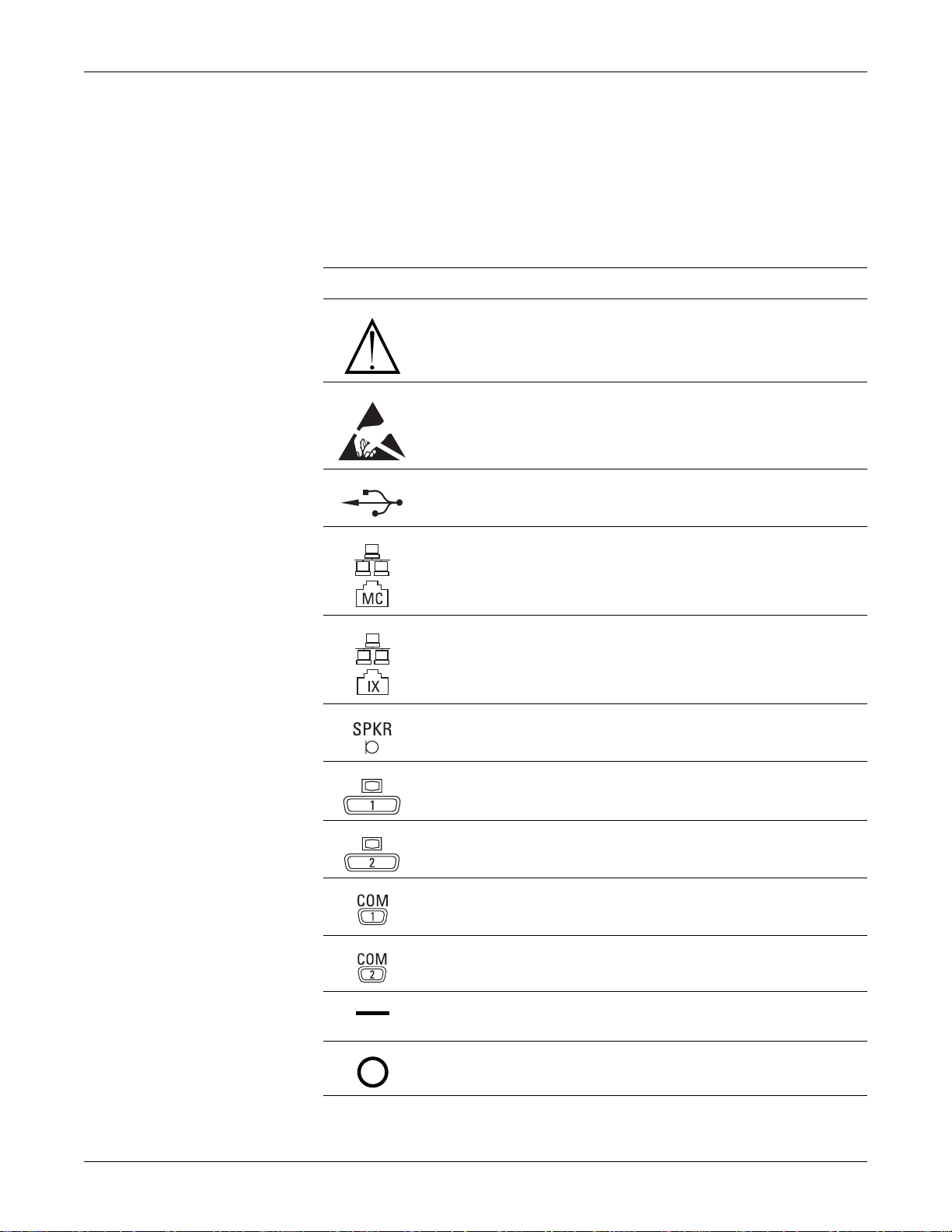
Equipment symbols
The following symbols appear on the equipment, but some symbols may not appear
on all equipment.
Symbol Description
Introduction: Equipment symbols
Equipment Symbols
ATTENTION: Consult accompanying documents before using the
equipment.
Provide electrostatic discharge damage protection.
USB connector port
Ethernet connector port used to connect to the Unity Network MC network.
Ethernet connector port used to connect to the Unity Network IX network.
External speaker connector port
Primary video output connector port
Secondary video output connector port
Primary serial communication connector port
Secondary serial communication connector port
Power switch indicator. Indicates the power switch is in the on position
when filled
Power Off: Indicates the power switch is in the OFF position.
2026419-002D CIC ProTM Clinical Information Center 1-11
Introduction: Equipment symbols
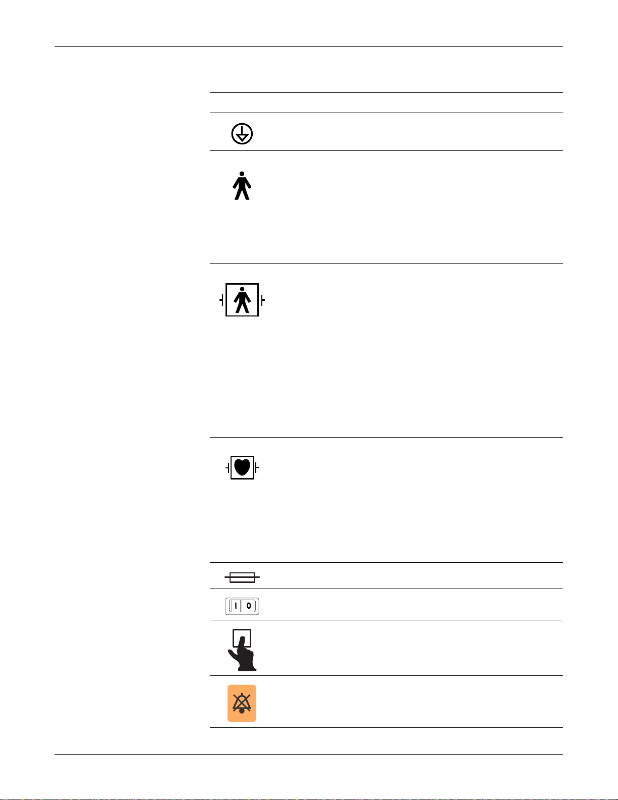
Equipment Symbols
Symbol Description
Equipotential stud. A ground wire from another device can be tied here to
ensure the devices share a common reference point.
Type B applied part: Non-isolated applied part suitable for intentional
external and internal application to the patient excluding direct cardiac
application.
[Medical Standard Definition:] Applied part complying with the specified
requirements of IEC 60601-1/UL 60601-1/CSA 601.1 Medical Standards to
provide protection against electric shock, particularly regarding allowable
leakage current.
Type BF applied part: Isolated (floating) applied part suitable for intentional
external and internal application to the patient excluding direct cardiac
application. “Paddles” outside the box indicate the applied part is
defibrillator proof.
[Medical Standard Definition:] F-type applied part (floating/isolated)
complying with the specified requirements of IEC 60601-1/UL 60601-1/
CSA 601.1 Medical Standards to provide a higher degree of protection
against electric shock than that provided by type B applied parts.
NOTE
The rating of protection against electric shock (indicated by symbol for
CF or BF) is achieved only when used with patient applied parts
recommended by GE Medical Systems Information Technologies.
Type CF applied part: Isolated (floating) applied part suitable for intentio nal
external and internal application to the patient including direct cardiac
application. “Paddles” outside the box indicate the applied part is
defibrillator proof.
[Medical Standard Definition:] F-type applied part (floating/isolated)
complying with the specified requirements of IEC 60601-1/UL 60601-1/
CSA 601.1 Medical Standards to provide a higher degree of protection
against electric shock than that provided by type BF applied parts.
Fuse. Replace the fuse with a fuse of the same type and rating.
Power
Writer door button
Silence Alarm keyboard key
1-12 CIC ProTM Clinical Information Center 2026419-002D
Introduction: Service requirements
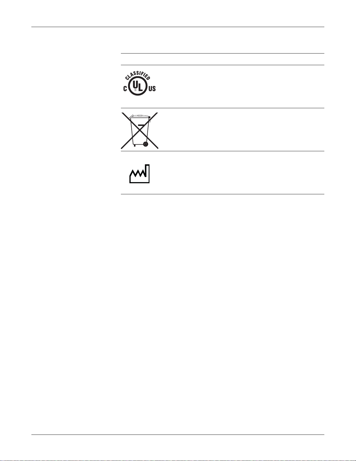
Equipment Symbols
Symbol Description
Medical Equipment. With respect to electric shock, fire and mechanical
hazards only in accordance with UL 60601-1 and CAN/CSA C22.2
NO.601.1.
4P41
This symbol indicates that the waste of electrical and electronic equipment
must not be disposed as unsorted municipal waste and must be collected
separately. Please contact the manufacturer or other authorized disposal
company to decommission your equipment.
This symbol indicates the date of manufacture of this device. The first four
digits identify the year and the last two digits identify the month.
2005-08
Service requirements
Follow the service requirements listed below, and in the “Maintenance” chapter of
this manual.
Refer equipment servicing to GE authorized service personnel only.
Any unauthorized attempt to repair equipment under warranty voids that
warranty.
It is the user’s responsibility to report the need for service to GE or to one of
their authorized agents.
Failure on the part of the responsible individual, hospi tal, or inst itution using
this equipment to implement a satisfactory maintenance schedule may cause
undue equipment failure and possible health hazards.
Regular maintenance, irrespective of usage, is essential to ensure that the
equipment is always functional when required.
2026419-002D CIC ProTM Clinical Information Center 1-13
Introduction: Equipment identification
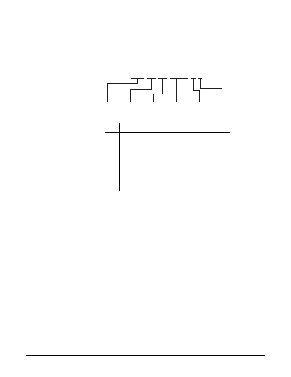
Equipment identification
Every GE device has a unique serial number for identification. A sample of the
information found on a serial number label is shown below.
### ## ## #### # #
123456
Description
1
Product code
2 Year manufactured
3 Fiscal week manufactured
4 Production sequence number
5 Manufacturing site
6 Miscellaneous characteristic
1. The product code for the CIC Pro center is SCH.
1
646A
1-14 CIC ProTM Clinical Information Center 2026419-002D

Manual information
Manual purpose
This manual supplies technical information for service representatives and technical
personnel so they can maintain the equipment to the assembly level. Use it as a
guide for maintenance and electrical repairs considered field repairable. Where
necessary, the manual identifies additional sources of relevant information and
technical assistance.
See the operator’s manual for the instructions necessary to operate the equipment
safely in accordance with its function and intended use.
Intended audience
This manual is intended for use by service representatives and technical personnel
who maintain, troubleshoot, or repair the equipment.
Conventions used
Introduction: Manual information
Revision history
Bold text Indicates keys on the keyboard, text to be entered, or hardware items
such as buttons or switches on the equipment.
Bold Italicized
text
Ctrl+Esc Indicates a keyboard operation. A plus (+) sign between the names of
<Space> Indicates you must press the spacebar. When instructions are given
Enter Indicates you must press the Enter or Return key on the keyboard.
The document part number and revision letter are listed at the bottom of each page
in this manual. The revision letter identifies the document’s update level. The
revision history of this document is summarized below.
Indicates software terms that identify menu items, buttons, or options
in various windows.
two keys indicates that you must press and hold the first key while
pressing the second key once.
For example, “Press Ctrl+Esc” means to press and hold down the
Ctrl key while pressing the Esc key.
for typing a precise text string with one or more spaces, the point
where the spacebar must be pressed is indicated as <Space>.
Do not type “enter”.
Revision History
Revision Comment
A Initial release of the document item number to develop the Bills of Material.
B Initial release of document content for limited customer use.
2026419-002D CIC ProTM Clinical Information Center 1-15

Introduction: Manual information
Revision History
Revision Comment
C Initial release of document for all customers world wide.
D Release of document with revisions to meet additional service requirements.
1-16 CIC ProTM Clinical Information Center 2026419-002D

2 Equipment overview
2026419-002D CIC ProTM Clinical Information Center 2-1
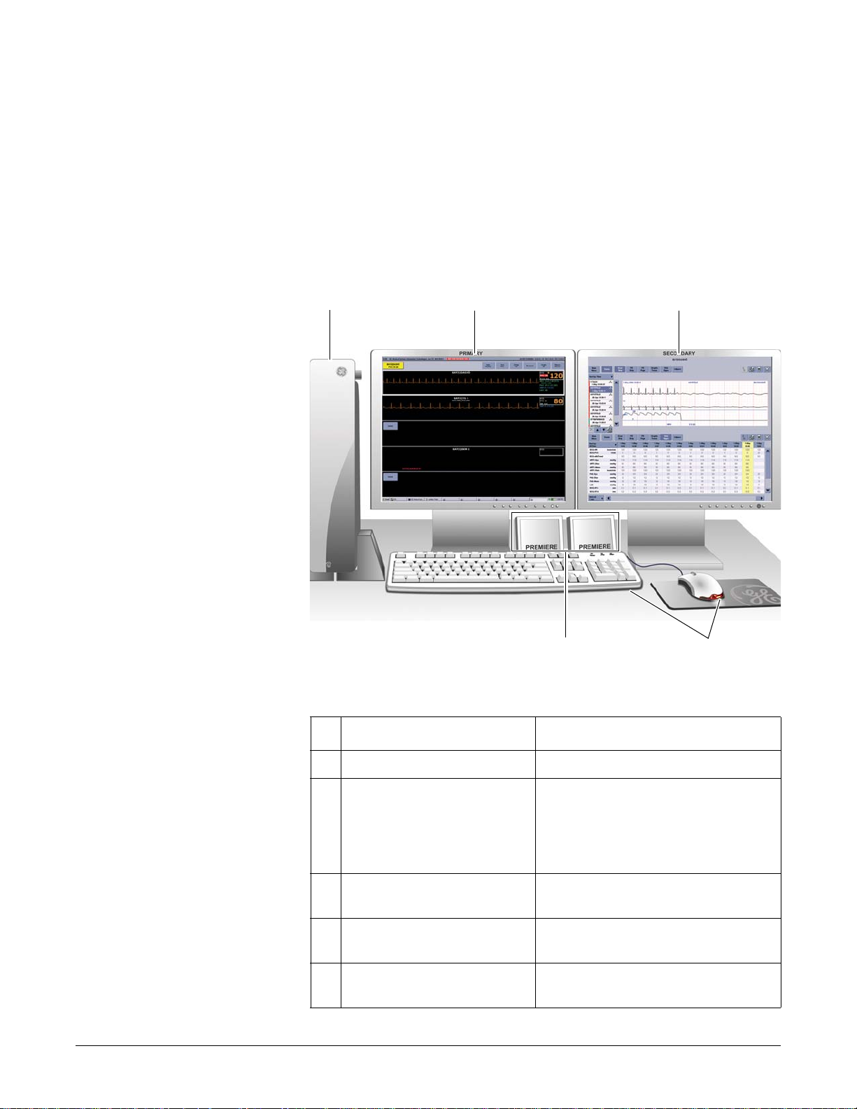
Standard components
Standard components include the following items:
Processor box
Primary display
External speakers
Standard keyboard
Standard mouse
12
5
Standard components
3
523B
4
Item Function
1 Processor box Run the CIC Pro center application.
2 Primary display Display real-time and stored patient data,
control windows, and various system-level
operations. Up to two displays may be
connected to the CIC Pro center
simultaneously.
3 Secondary display (optional) Display stored patient data and browser
information.
4 Standard mouse and keyboard Enter data, navigate menus, and choose
options.
3 External speakers Sound audible patient status and system
status alarm tones.
2-2 CIC ProTM Clinical Information Center 2026419-002D
Equipment overview: Standard components
Primary display
The CIC Pro center supports either a standard 19-inch or 20-inch color display or a
standard 19-inch or 20-inch color touchscreen display. See “Optional components”
on page 8-9.
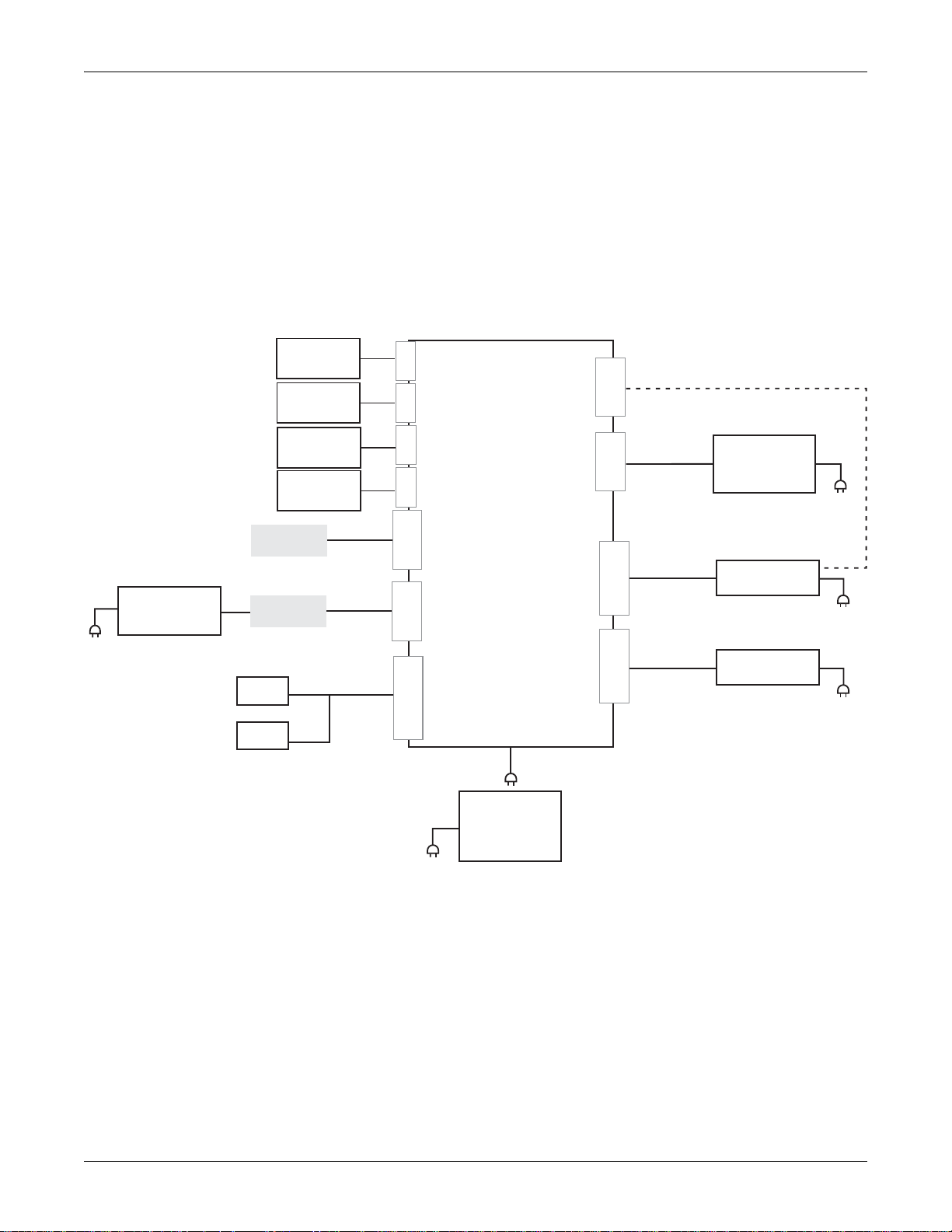
Processor box
System interconnection diagram
Laser printer
(Optional)
MC Unity
Network
IX Unity
Network
Speaker
Speaker
Mouse
Keyboard
Touchscreen
USB cable
USB to parallel
printer adapter
Network
Network
cable
cable
USB
PORT
USB
PORT
USB
PORT
USB
PORT
PORT
ETHERNET
PORT
ETHERNET
PORT
SPEAKER/AUDIO
CIC Pro
Computer
COM 1
SERIAL PORT
COM 2
DDW cable
SERIAL PORT
DVI
PORT
Monitor cable
DVI
PORT
Monitor cable
Touchscreen serial cable
(Optional)
PRN-50, digital
writer (Optional)
Primary display
Secondary display
(Optional)
(Optional)
Uninterruptable
power supply
(Recommended)
695A
2026419-002D CIC ProTM Clinical Information Center 2-3
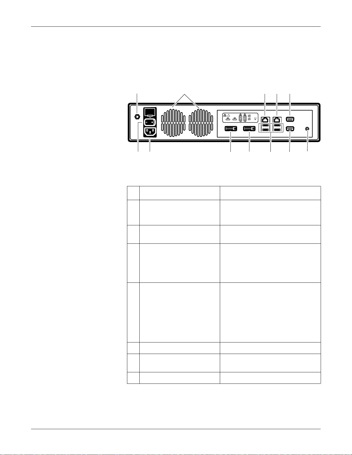
Back panel
Equipment overview: Standard components
The back panel of the processor box has the following connectors, ports, receptacle,
and switch.
1
12 9
2
10
3
4115
8
7
6
Back panel of the processor box
Item Function
1 Equipotential stud Connect a ground wire from another device
to ensure the devices share a common
reference point.
2 Ventilation ports Vent internal processor heat to the outside of
the processor box.
3 Unity Network MC Ethernet port
Interface with other networked GE patient
monitoring and telemetry system devices.
Display waveform, parameter, and alarm
condition data from other networked
devices.
031A
4 Unity Network IX Ethernet port
Connect to an optional network laser
printer.
Share licenses with other CIC Pro centers
within the same care unit.
Display full disclosure data.
Access remote serviceability.
Provide access to data and servers
outside of your facility.
5 COM 1 port Connect to the touchscreen display.
6 External speaker port Connect to external speakers to hear patient
and system status alarm notification.
7 COM 2 port Connect to the PRN 50-M digital writer.
2-4 CIC ProTM Clinical Information Center 2026419-002D

Controls
Mouse
Equipment overview: Standard components
Item Function
8 USB ports There are four USB ports you can use to
connect the following devices:
Standard mouse.
Standard keyboard.
Touchscreen displays.
USB Memory stick. (Used to activate CIC
Pro center licenses.)
9 Primary video port Connect to the primary display.
10 Secondary video port Connect to an optional secondary display.
11 Power receptacle Connect the power cable.
12 Power switch Press to turn on or to turn off.
NOTE
If the MultiKM license is activated, you can connect one keyboard and one
mouse to a group of centralized and configured CIC Pro centers. When the
(MultiKM icon) appears in the lower right corner of the display screen, the
MultiKM license is activated on this CIC Pro center.
With the MultiKM license activated, you can do the following tasks:
Move the mouse across all CIC Pro centers in the group.
Access any CIC Pro center’s display screen or enter text into any of the
CIC Pro center’s text fields in the group.
Support right and left mouse clicks and scroll wheel movement.
Use a standard mouse to select menu options or patient data.
NOTE
When using the MultiKM software application, you may use one mouse and one
keyboard across multiple centralized CIC Pro centers.
Using the mouse
Clicking refers to positioning the mouse pointer on a selection and pressing the
left mouse button once.
Right clicking refers to clicking the ri ght mouse button.
This displays a control setting menu that allows you to temporarily adjust some
of the defaults or to select a different patient bed to view. See the “CIC Pro
Clinical Information Center Operator’s Manual” for details.
2026419-002D CIC ProTM Clinical Information Center 2-5

Equipment overview: Standard components
Mouse pointer shapes
Depending on the operation mode of the CIC Pro center, the mouse pointer changes
its appearance.
Pointer Function
Arrow: Indicates the CIC Pro center center is operating in user
mode.
Use the arrow pointer to select menu options, patient data, and to
navigate from window to window.
024A
I-beam: Indicates the pointer is in a data entry field.
Enter text when this pointer is displayed.
025A
Cross: Indicates the CIC Pro center center is operating in
service mode.
WARNING
026
QUALIFIED PERSONNEL — The service mode
is intended for use only by qualified personnel
with training and experience in its use. The
consequences of misuse include loss of alarm
configuration, loss of patient data, corruption of
the CIC Pro center operating system software, or
disruption of the entire Unity Network.
Keyboard
Use a standard keyboard to type text into a data entry field.
NOTE
When using the MultiKM software application, you may use one mouse and one
keyboard across multiple centralized CIC Pro centers.
Typing text into a data entry field
To type text into a data entry field, position the mouse pointer over the data entry
field. When the mouse pointer changes to an I-beam, click the left mouse button and
begin typing.
Silence Alarms keyboard key
019A
2-6 CIC ProTM Clinical Information Center 2026419-002D

Equipment overview: Optional components
NOTE
If the MultiKM license is activated, you must position the mouse cursor in the
patient window of the CIC Pro center where the alarm condition is occurring.
Then press the Silence Alarms keyboard key to silence all alarms on this CIC
Pro center for one minute.
Press the Silence Alarms key to silence all alarms for one minute. Alarms that are in
queue to sound are also silenced. Any new patient alarm condition cancels the alarm
silence, breaking through to sound the new alarm.
Indicator
The power indicator is located on the front left side of the CIC Pro center’s
processor box. The power indicator illuminates green when the power is turned on.
Optional components
Optional components include the following items:
Secondary display
Touchscreen display
Remote display with speakers
Laser printer
PRN 50-M digital writer
Un-interruptible power supply (UPS)
Secondary display
Up to two displays may be connected to the CIC Pro center
simultaneously.
From a secondary display, you can do the following:
View all of the single viewer applications.
Use the second display as a review display.
View two single applications at the top and bottom half of the screen.
View all applications (excluding Multi-view) in this second display.
Navigate between applications via the enhan c ed software tools provided.
Access custom views of routine applications using a single mouse click.
The following requirements apply when using a secondary display with your CIC
Pro center:
Secondary display monito rs must be the same type and the same size as the
primary display monitor. Only use the 19-inch or 20-inch display monitors that
are validated for use with the v5 CIC Pro center.
Secondary display monito rs and primary disp lay monitors must be set to the
same 1280 x 1024 display resolution. No other display resolutions have been
validated for use with the v5 CIC Pro center.
Secondary display monito rs can be a combin ation of touchscreen and non-
touchscreen displays.
2026419-002D CIC ProTM Clinical Information Center 2-7

Touchscreen display
Equipment overview: Optional components
Secondary display monitors will not function until you have first completed the
following tasks:
Activate the LVSL or the LVSM license.
Activate the DDIS license.
Restart the CIC Pro center.
A touchscreen display allows you to select any selectable screen object by gently
tapping the object with your finger.
NOTE
The touch screen display does not allow you to disp l a y th e right click menu.
The following guidelines apply to using a touchscreen display:
Applying tape or other items to the screen impairs the touchscreen’s
functionality.
Using pencils, pens, or other sharp, pointed objects can dam a ge the
touchscreen.
Remote display with speakers
Networked remote displays can provide a duplicate (mirror image) view of a
primary CIC Pro center. When speakers are connected to the remote displays,
audible alarm tones can also be sounded.
Laser printer
A laser printer can be connected to the CIC Pro center to print the following patient
data:
Alarm graphs
ECG numeric data and waveforms
12 lead ECG
Arrhythmia events
Events
Caliper measurements
Full disclosure
Graphic trends
ST alarm trends
Vital signs
WARNING
SHOCK HAZARD — Laser printers are UL 60950/IEC 60950
certified equipment, which may not meet the leakage current
requirements of patient care equipment. This equipment must not
be located in the patient vicinity unless the medical system
standard IEC 60601-1-1 is followed.
2-8 CIC ProTM Clinical Information Center 2026419-002D

PRN 50-M digital writer
Equipment overview: Optional components
Do not connect a laser printer to a multiple portable socket outlet
(MPSO) supplying patient care equipment. The use of an MPSO
for a system will result in an enclosure leakage current equal to the
sum of all the individual earth leakage currents of the system if
there is an interruption of the MPSO protective earth cond uctor.
A PRN 50-M digital writer can be connected to the CIC Pro center to print the
following patient data on 2-inch wide paper:
Alarm graphs
ECG numeric data and waveforms
Graphic trends
Vital signs
The following controls, indicators, and connectors are located on the digital writer.
56
4
3
9
2
1
8
7
PRN 50-M digital writer: front and back views
Item Function
1 Writer door button Press to open the door and replace the writer
paper.
2 Graph stop button. Press to stop printing a graph.
030A
3 Paper out indicator. Illuminates when you need to
replace the paper. See “Changing writer paper” on
page -8.
2026419-002D CIC ProTM Clinical Information Center 2-9

Equipment overview: Theory of operation
Item Function
4 Power indicator. Illuminates when the writer is
5 Power switch Press to turn on or turn off the writer.
6 Power connector Connect the writer’s power cable.
7 Power cable clamp Connect to the writer’s power cable. This prevents
8 M-port connector Connect to the CIC Pro center’s COM 2 port.
9 ASYNC COMM port Not used.
Un-interruptible power supply (UPS)
WARNING
If power to the CIC Pro center is lost, patient monitoring
information will no longer be displayed or stored.
connected to a power source.
the cable from being pulled out of the power
connector.
GE recommends using an un-interruptible power supply with the CIC Pro center.
Without a UPS, power line outages may result in:
Theory of operation
Functional description
The CIC Pro center application is designed to provide real-time patient data and
alarms for central nurses’ stations in hospitals. It can display real-time waveforms
and vital sign data, with visual and audible alarms, for up to 16 patients
simultaneously. The CIC Pro center supports both hardwired and telemetry data.
The CIC Pro center software allows users to select any bed on the Unity Network
MC network and display an expanded view of that bed’s real-time parameters and
waveforms. This expanded view also allows users to view and modify settings
within the care unit, and view a patient’s other data (including alarm histories,
graphic trends and tabular trends).
The user can configure the number of patients displayed by the system, and the
number of displayed waveforms per patient. Waveform colors are configurable.
Improper shut down of the CIC Pro center, causing lengthy disk scan
procedures on reboot.
Data loss.
All configuration data is stored, and is restored after a system power cycle or
software restart.
The CIC Pro center is connected to the Unity Network MC network via the Ethernet.
2-10 CIC ProTM Clinical Information Center 2026419-002D

Physiological data
Periodic data
Equipment overview: Theory of operation
CIC Pro centers trend two types of physiological data: periodic and episodic.
Periodic data is constantly updated. Data is sampled every two seconds to yield 30
samples per minute. The displayed value is the median of the 30 samples. It is
always the median of a one-minute time frame, regardless of the interval selected.
The interval is the time between values, not the time of the value itself. For example,
a five minute interval means one minute samples spaced five minutes apart, not five
minute samples, and not a median of the five one minute samples. Odd number
values are rounded down to the nearest even number.
If the calibration of the system clock changes (for example, daylight savings time),
the “time” for periodic data “slides” into the revised time. However, episodic data is
time-stamped and retains its original time.
Examples of periodic data include heart rate (HR) and blood pressure (BP).
Episodic data
Episodic data are events that are user, or system, generated. Examples of episodic
data include temperature (Temp) and non-invasive blood pressure (NBP).
File or data management
Log files
Log files generated by the CIC Pro center application, other associated applications
and the CIC Pro center operating system are used during system analysis, problem
diagnosis and troubleshooting. See “Log Files” on page 5-14 for more information
about log files.
RWHAT packets
All monitoring devices on the GE Unity Network periodically broadcast information
about themselves in “RWHAT” packets. Among other things, RWHAT packets
contain IP address, port number, name, and offered services information about each
device.
All monitoring devices listen for RWHAT packets, and maintain a database of
information about other devices on the network. When devices need to
communicate, the appropriate IP address information is obtained from the database,
Unity Network-protocol messages are created, and operating system services are
used to transmit the message on the network.
For example, when a CIC Pro center computer communicates with a telemetry
device, the telemetry device’s IP address is retrieved from the CIC Pro center
computer RWHAT database, the Unity Network messages are created, and the CIC
Pro center Windows operating system sends the messages to the telemetry device.
2026419-002D CIC ProTM Clinical Information Center 2-11

Storage
Printing
Equipment overview: Theory of operation
The FD Data interface uses the Unity Network IX network to retrieve data from
the database.
Each bed is stored in a separate directory, containing one index file and many
record files.
The FD Page printout is a configurable, long-time-period overview of
waveform activity. It is activated by clicking the (print button) located in
the top right corner of the FD Page window.
The FD Strip printout is a quick snapshot of what is currently on the screen. It
is activated by clicking the (print button) while the FD Page is being
viewed.
There is a separate full disclosure printer selection fro m the main laser printer
selection on the setup page. Specifying a printer here does not advertise this
CIC Pro center as a print server on RWHAT (like the main laser selection). It is
used exclusively by the local FD system. A printer must be “Added” to the
operating system before it will show up in the drop-down list.
2-12 CIC ProTM Clinical Information Center 2026419-002D

Licensing
Full disclosure
Equipment overview: Theory of operation
All features and functions of the CIC Pro center are determined by the licenses
activated and running on each CIC Pro center. Licenses are specific to each
individual CIC Pro center’s serial number, are node locked, and cannot be used
(floated) by another CIC Pro center.
The CIC Pro center full disclosure (FD) system stores all waveform and parametric
data from a patient for up to 76 hours. This data can be randomly accessed later in a
static display that looks similar to the real-time display window. T o accomplish this,
every Unity Network waveform packet (4/sec) and every parameter packet (1 every
2 seconds) is stored on the CIC Pro center. In addition, one R WHAT packet and one
admit packet is stored every minute to help recreate the patient’s history.
Unlike an alarm history event stored at the bedside, which only stores a 10 second
snap shot surrounding the event, full disclosure allows the user to scroll back in time
(prior to the event and leading up to the event).
Behaviors or rules
Licensing
Installation
Incompatible wit h old F D system (prior to CIC Pro center v3.x).
Certain Unit Defaults are incompatible with CIC Pro center v3.x systems.
Start-up modes
Auto For All: Automatically detects admitted beds that are not currently storing
full disclosure data anywhere and attempts to start full disclosure on one of the
CIC Pro centers within the care unit. This works regardless of whether the bed
was admitted directly at the bedside or the CIC Pro center. Full disclosure
cannot be stopped on a particular bed until the bed is discharged.
Auto If Listed: Same as Auto For All, but only if the bed in question is entered
into the list on the FD Unit Defaults setup screen. All other beds are not storing
full disclosure data.
Manual Mode: Beds are not automatically storin g ful l disclosure data upon
admission. Users can manually start and stop full disclosure for a particular bed
by using a button located on the CIC Setup > Full Disclosure Defaults
window. All full disclosure data is deleted when full disclosure is stopped for a
bed. See the “CIC Pro Clinical Information Center Operator’s Manual” for
more information.
Support for up to 16 patients per CIC Pro center.
Stores 76 hours of data per patient regardless of license type. Licensing controls
amount of data that is viewable.
Unit Licensing Mode sets which type of licen se is requested. Supported types:
None (1 hour), 24, 48, 72 hours.
2026419-002D CIC ProTM Clinical Information Center 2-13

Control
Equipment overview: Theory of operation
Failure to obtain a license results in one hour of viewable full disclosure.
Licensing information is stored with data, so restrictions follow data regardless
of where it is viewed, even if viewed in a different care unit with a different
Unit License Mode.
CIC Pro center master and full disclosure
NOTE
There is only one master CIC Pro center per care unit (with respect to full
disclosure). The CIC Pro center with the lowest IP address becomes the master.
CIC Pro center master perform the following activities in one minute increments:
Detects admitted (but not full disclosure data collection) beds within the care
unit, for Auto modes.
Assigns beds (for full disclosure acquisition) to CIC Pro centers within the care
unit.
Applies Multi-FD and Twin-Bed Rules.
Uses the FDSvr process to find the FULL DISCLO service, identifying CIC
Pro centers with full disclosure capability. The FULL DISCLO service is used
by the CIC Pro center master while searching for other CIC Pro centers to
query, control, and assign beds.
NOTE
The CIC Pro center master checks the software versions of the other CIC
Pro centers before trying to identify CIC Pro cen ters with full disclosure
capability . Software versions earlier than 2.5 are ignored.
Uses the LocateFD service (provided by FDSvr) to guarantee that the right CIC
Pro center is contacted if retrieving data while a multi-full disclosure condition
is occurring.
NOTE
A CIC Pro center will not act as master during the first minute after it starts up.
Instead, the latest data is first collected from the other CIC Pro centers on the
network, and this data determines which CIC Pro center becomes master.
Multiple masters on a network might occur, but only briefly (this will selfcorrect within a couple of minutes).
Minute rule or the Offline Storage setting
(see “Set the Full Disclosure Defaults” on page 4-45):
The Offline Storage setting determines the length of time the CIC Pro center will
maintain full disclosure data for a bed from which it has stopped receiving data (e.g.,
a NO COMM condition).
If the NO COMM condition ends within the Offline Storage setting time frame,
full disclosure data collection for the bed continues.
2-14 CIC ProTM Clinical Information Center 2026419-002D

Equipment overview: Theory of operation
If a NO COMM condition exceeds the Offline Storage setting time frame, all
data for the bed is deleted. If (while in Auto mode) the bed comes back online
(the NO COMM condition ends) after this point, the bed is reassigned as a new
and different bed.
When full disclosure starts up on a CIC Pro center, it determines when data was
last received from the assigned beds.
If the latest data for a bed:
Is not older than the Offline Storage setting, then full disclosure data
collection continues for the bed.
Is older than the Offline Storage setting, existing data associated with the
bed is deleted, and new data collection is started for the bed.
Multi-full disclosure rule
If multiple CIC Pro centers are running in a care unit, the Multi-full disclosure rule
allows the switching of full disclosure data collection from one CIC Pro center to
another, if a CIC Pro center goes offline (e.g., reboot, shutdown, etc.).
The following examples describe how the Multi-full disclosure rule works when
using two CIC Pro centers (CICA and CICB).
NOTE
In the examples, start up mode is Auto, and only one bed (BED1) is used.
Example 1:
719A
1. CICA goes offline and stops full disclosure data collection on BED1. This
causes CICB to begin full disclosure data collection on BED1.
NOTE
The master CIC Pro center detects CICA going offline, and switches full
disclosure data collection over to CICB, within a minute of the offline
event occurring.
2. CICA comes back online within the Offline Storage setting time frame, and
continues full disclosure data collection on BED1 again. At this point, CICA
and CICB are both collecting full disclosure data on BED1.
3. The Multi-full disclosure rule does not allow more than one CIC Pro center to
collect full disclosure data from the same bed at the same time--only the data
that goes the farthest back in time (CICA) is kept. Because of this, CICA
continues collecting full disclosure data on BED1, and CICB stops.
2026419-002D CIC ProTM Clinical Information Center 2-15

Equipment overview: Theory of operation
Example 2:
1. CICA goes offline and stops collecting full disclosure data on BED1. This
causes CICB to begin collecting full disclosure data on BED1.
NOTE
The master CIC Pro center detects CICA going offline, and switches full
disclosure data collection over to CICB, within a minute of the offline
event.
2. CICA comes back online after exceeding the Offline Storage setting time
frame. Because of this, existing BED1 data is deleted from CICA, and the new
BED1 data collection begins on CICA. At this point, CICA and CICB are
BOTH collecting full disclosure data on BED1.
3. The Multi-full disclosure rule does not allow more than one CIC Pro center to
collect full disclosure data from the same bed at the same time (only the data
that goes the farthest back in time (CICB) is kept). Because of this, CICB
continues collecting full disclosure data from BED1, and CICA stops.
720A
NOTE
At every wake-up cycle (1 minute interval), the CIC Pro center master scans all
CIC Pro centers within the care unit to determine if more than one CIC Pro
center is collecting full disclosure data from the same bed (this can happen as
part of normal operation). If the master detects this condition, all CIC Pro
centers are instructed to stop collecting full disclosure data from the bed except
for the one CIC Pro center with the oldest data for the bed.
Combo mode (Twin-bed rule)
In combo mode:
1. Two beds are on the network: one is a hardwired bed, and the other is telemetry
bed. Both beds share the same name (e.g. BED), but '*' is appended to the
telemetry bed name (e.g. BED and BED*). Both beds represent the same
patient.
NOTE
If the CIC Pro center was not functioning in combo mode, these two beds
would be treated as distinct and separate.
2. Only the oldest bed data is kept. Data for the other bed is deleted.
3. No matter which data is kept, full disclosure data collection continues, and the
data is stored under the bed name, but without the '*'.
Combo mode is stopped (breaking combo) by discharging either
bed. If this happens, full disclosure data collection continues on
the undischarged bed, and the data is stored under the
undischarged bed name.
2-16 CIC ProTM Clinical Information Center 2026419-002D

Equipment overview: Theory of operation
NOTE
If the hardwired bed is discharged, '*' would again be included in the
name.
To follow are combo mode examples:
Combo Mode Example 1:
a. A hardwired bed BED is admitted and full disclosure data is collected.
b. A telemetry bed BED* is admitted and full disclosure data is collected.
T wo separate full disclosure data stores exist, one for each bed (possibly on
a different CIC Pro centers).
c. The two beds are put into combo mode. When this happens, BED data is
kept because it is older than BED* data, and BED* data is deleted. Full
disclosure data collection continues, and the data is stored under the name
BED.
714A
d. Combo is broken by discharging BED*. Full disclosure data collection
continues, with the data still stored under the name BED.
Combo Mode Example 2:
a. A hardwired bed BED is admitted and full disclosure data is collected.
b. A telemetry bed BED* is admitted and full disclosure data is collected.
T wo separate full disclosure data stores exist, one for each bed (possibly on
a different CIC Pro centers).
c. The two beds are put into combo mode. When this happens, BED data is
kept because it is older than BED* data, and BED* data is deleted. Full
disclosure data collection continues, and the data is stored under the name
BED.
d. Combo is broken by discharging BED. Full disclosure data collection
continues, and the data is now stored under the name BED*.
715A
2026419-002D CIC ProTM Clinical Information Center 2-17

Equipment overview: Theory of operation
Combo Mode Example 3:
a. A telemetry bed BED* is admitted and full disclosure data is collected.
b. A hardwire bed BED is admitted and full disclosure data is collected. Two
separate full disclosure data stores exist, one for each bed (possibly on a
different CIC Pro centers).
c. The two beds are put into combo mode. When this happens, BED* data is
kept because it is older than BED data, and BED data is deleted. Full
disclosure data collection continues, and the data is stored under the name
BED*.
d. Combo is broken by discharging BED*. Full disclosure data collection
continues, and the data is still stored under the name BED.
716A
Combo Mode Example 4:
a. A telemetry bed BED* is admitted and full disclosure data is collected.
b. A hardwired bed BED is admitted and full disclosure data is collected. T wo
separate full disclosure data stores exist, one for each bed (possibly on a
different CIC Pro center).
c. The two beds are put into combo mode. When this happens, BED* data is
kept because it is older than BED data, and BED data is deleted. Full
disclosure data collection continues, and the data is stored under the name
BED.
d. Combo is broken by discharging BED. Full disclosure data collection
continues, and the data is now stored under the name BED*.
Bed Name/IP Address Changes
The CIC Pro center tracks full disclosure data for individual beds using a
combination of the bed name and IP address.
717A
If a bed name changes during full disclosure data collection, information within the
data reflects the new name at the point the name change occurred.
If a bed IP address changes during full disclosure data collection, but the name does
not, it is interpreted as a new and different bed, and a new full disclosure data store
is created and utilized for the new bed.
2-18 CIC ProTM Clinical Information Center 2026419-002D

Unit Boundary
Equipment overview: Networking
If a bed goes offline, and another bed with the same name but a different IP address
comes online, it is interpreted as a new and different bed and a full disclosure data
store is created and utilized for it. However, the following conditions apply:
If the bed that went offline (with the original IP address) comes back online
within the Offline Storage setting time frame, the two beds continue to be
treated as separate, since the different IP addresses positively identify them as
distinct and separate.
If the bed that went offline (with the original IP address) does not come back
online within the Offline Storage setting time frame, the bed with the new IP
address is interpreted as a replacement for the bed with the original IP address.
In this case, the full disclosure data for the bed with the original IP address is
deleted, and full disclosure data collection continues, and the data is stored
under the bed with the new IP address only.
Each care unit operates independently with respect to full disclosure. The only
interaction is when displaying data across care units.
License mode: All beds within a care unit will have access to the same amount
of data storage (based on time) unless there is a failure to get a license (1 hour).
Can be different across different care units (e.g., UnitA-72hours, UnitB-None (1
hour).
Start-up mode: The same start-up rules apply to all beds within a care unit.
Default: The same full disclosure defaults are used on all CIC Pro centers
within a care unit.
Master: One per care unit.
Acquisition/Storage: The master CIC Pro center will only assig n beds wit hin
the care unit to CIC Pro centers within that care unit. At no time will data for a
bed be stored on a CIC Pro center in a different care unit.
Bed Unit Changes: If a bed changes it s care unit name during full disclosure
data collection, all data for the bed is deleted. The care unit where the bed
moved becomes responsible for the bed.
CIC Pro center Unit Changes: If a CIC Pro center changes its care unit name
during full disclosure data collection, all data for all beds being having full
disclosure data collected by that CIC Pro center is deleted. The care unit with
the original name is responsible for the beds.
Networking
Patient monitoring network
The CIC Pro center processes and displays real-time data acquired from up to 16
networked GE monitors or telemetry transmitters connected to the Unity Network.
When patient data is acquired from ApexPro telemetry transmitters (telemetry beds),
the data is transmitted to a telemetry receiver where it is then transferred to the Unity
Network via a wired connection. The CIC Pro center displays this telemetry bed
patient data along with the patient data acquired from other monitors.
2026419-002D CIC ProTM Clinical Information Center 2-19

Equipment overview: Networking
Web access server network
WARNING
INTERNET EXPLORER FAVORITES—S aving Internet
Explorer Favorites (bookmarks) for web pages containing patient
data is not recommended. Doing so may result in patient data
displayed in Internet Explorer not matching the patient’s medical
number on the Launch Pad or iPanel application toolbar.
CAUTIONS
SECURITY—The healthcare institution is responsible for
ensuring the privacy of any protected health information that is
displayed on this device.
SECURITY—The web browser which runs in conjunction with
the CIC Pro center is intended for hospital intranet use only. If
confidential patient information is made available from the
hospital intranet, the security of the data is the responsibility of the
hospital.
The CIC Pro center can provide access to a Citrix Client or an intranet browser for
viewing other applications (e.g., the hospital information system) or other sources of
patient data (e.g., labs, images, or MUSE
Access to a Citrix server or intranet server depends upon how your CIC Pro center is
configured and your on-site information technology offerings.
To set up a Citrix Client, see “Setting up a Citrix client” on page 4-27.
CITRIX Intranet web portal
You can use the Citrix Client to view patient data from other data systems or
repositories.
Complete the following steps to access the Citrix server:
1. From the multi-patient viewer, click Browser. The Browser window displays.
2. From the menu bar, click Citrix to display the Citrix window.
Web browser intranet web portal
™
Cardiology Information System data).
WARNING
LOSS OF MONITORING — If the browser function is
inappropriately used, loss of monitoring function may result. Use
alternate monitoring devices or close patient observation until the
monitoring function at the CIC Pro center is restored.
When using the browser, follow these restrictions:
2-20 CIC ProTM Clinical Information Center 2026419-002D

Equipment overview: Networking
Do not attempt to access the file systems of the CIC Pro
center through the use of the browser.
Do not attempt to download files of any type. This includes,
but is not limited to, audio or video files.
The CIC Pro center can provide a web portal to access and view other in-hospital
web applications or other sources of patient data. This web browser option is at the
top right corner of the title bar of the CIC Pro center display screen. Select this
button to start a separate Microsoft Internet Explorer
TM
application.
If a patient monitoring alarm occurs while the browser is open, the CIC Pro center
application window moves to the foreground of the display, and the browser window
moves to the background of the display. To restore the browser window, select the
Browser option again or select the Internet Explorer button from the lower task bar.
The web browser runs independently of the CIC Pro center application. However, if
the CIC Pro center detects 15 minutes of web browser inactivity, the web browser
window closes. Subsequent web browser activity then requires you to select the
Browser option to restart the program.
Complete the following steps to access the intranet browser application:
1. From the multi-patient viewer, click Browser. The web access server window
displays.
2. Click Browser to display the intranet browser application.
3. Under Favorites, click the web site you want to access.
2026419-002D CIC ProTM Clinical Information Center 2-21

Equipment overview: Patient data interface
Patient data interface
The CIC Pro center allows you to view patient data using two different viewers,
varying in data granularity:
Multi-patient viewer
Single patient viewer
Multi-patient viewer
The multi-patient viewer displays a snapshot of real-time waveform data and
parameter numeric data for a maximum of 16 patients.
The following picture identifies different areas of the multi-patient viewer.
2 3 41
601A
7
8
Multi-patient viewer
Description
1 Alarm buttons. Show the care unit name, bed number, and the cause of the
alarm. This screen location is also known as the Alarm Display Unit (ADU) line.
2 Colored border alarm indicator. The patient window is outlined in red or yellow
to identify a patient alarm condition. The alarm message is also displayed.
3 Alarm message.
2-22 CIC ProTM Clinical Information Center 2026419-002D
6
5

Equipment overview: Patient data interface
Multi-patient viewer
Description
4 Multi-viewer menu bar buttons. See the CIC Pro Clinical Information
Center Operator’s Manuals for details.
5 Additional parameter information.
6 Patient name and Unit Name / Bed Name.
NOTE
The source of a patient’s parameter data can be from a monitor, a
telemetry transmitter, or from both a monitor and a telemetry
transmitter. To prevent the duplication of bed names and to help
you identify the parameter data source, the CIC Pro center appends
the following symbols to the bed name:
no symbol = monitor (e.g. Unit Name/Bed Name).
* = telemetry bed (e.g. Unit Name/Bed Name*).
+ = monitor with a Unity Network ID connection (e.g. Unit
Name/Bed Name+).
*+ = telemetry bed with a Unity Network ID connection (e.g.
Unit Name/Bed Name*+).
Single patient viewer
7 Real-time trend window.
8 Empty patient window displaying an Admit window.
The single patient viewer allows you to view detailed real-time or stored parameter
data for one patient.
The following picture identifies different areas of a single patient viewer window.
12 3
640A
2026419-002D CIC ProTM Clinical Information Center 2-23

Patient data
Real-time patient data
Equipment overview: Patient data
Single patient viewer
Item Description
1 Single patient viewer menu buttons.
2 Expanded waveform data.
3 Single patient viewer control buttons
You can view real-time patient data or retrieve and view patient data that has been
collected and stored at the CIC Pro center.
Monitored parameters
Real-time trend window
The CIC Pro center can retrieve and display many different types of parameter data
from patient monitors connected to the Unity Network It can also retrieve and
display many different types of parameter data from secondary devices connected
through a Unity Network Interface.
NOTE
A more complete list of supported parameters is included in the “CIC Pro Clinical
Information Center Operator’s Manual.”
For detailed parameter monitoring instructions, see the appropriate monitor or
telemetry system operator’s manual.
For detailed clinical and troubleshooting information, see the “Critical Care
Monitoring Clinical Reference and Troubleshooting Guide.”
The multi-patient viewer can be configured to display a real-time trend window.
This trend window displays the recent trends for a maximum of two parameters.
Each trend contains one hour of data displayed at one minute intervals. When you
2-24 CIC ProTM Clinical Information Center 2026419-002D

Equipment overview: Patient data
see a trend variation, you can review this trend more closely from the Graphic
Trends tool.
Stored patient data
603A
Real-time trends display from left (olde r data) to right (newer data)
To review a trend, click in the real-time trend window. The single patient viewer
automatically displays the Graphic Trends window for this patient.
To configure the real-time trend window, see the “CIC Pro Clinical Information
Center Operator’s Manual.”
You retrieve in-unit parameter data from patient monitors connected to the Unity
Network and retrieve parameter data from secondary devices connected through a
Unity Network Interface. In addition, can use the following CIC Pro center patient
data review tools to examine the data more closely:
Events: Review any crisis, warning , or advisory level arrhy thm ia event or ST
event that is saved in the Events directory. You can also view saved ST
references and sample ECG waveforms.
Event st rip: Review 10-second snapshot of event data. The strip displays 5-
seconds of data before the event occurred and 5-seconds of data during the
event.
FD Strip: Review a 10-second snapshot of available full disclosure parameter
waveforms and values. You can scroll through the displayed data to change the
2026419-002D CIC ProTM Clinical Information Center 2-25

Service interfaces
Equipment overview: Service interfaces
data’s time focus.
FD Page: Review a maximum of 72 hours of the most current full disclosure
waveform and parameter numeric data. The amount of full disclosure data
collected for a patient is determined by the type of licenses installed on the CIC
Pro center.
Graphic Trends: Review parameter numeric data over a specified period of time
in bar graph format.
Vital signs: Review parameter numeric data values for monitored parameters
over a selected period of time.
Calipers: Record measurements on the ECG waveforms
The CIC Pro center provides local, on-site remote, and off-site remote service
interfaces for configuring, troubleshooting, and completing some of the checkout
procedures.
See Chapter 5, “Service interfaces” .
2-26 CIC ProTM Clinical Information Center 2026419-002D

3 Installation
2026419-002D CIC ProTM Clinical Information Center 3-1

The installation process
After un-crating your equipment and inspecting it for damage, you can begin the
physical installation process of the CIC Pro center. The following graphic illustrates
the pre-installation requirements and the physical installation process flow:
Completing pre-installation requirements
“Complete product
training”
“Verify care unit software
and hardware
compatibility”
“Verify proper electrical
grounding”
Installing the equipment in the care unit
“Connect the cables and
peripheral devices”
“Gather required tools”“Complete a site survey”
“Verify the use of an uninterruptible power supply
(UPS)”
“Turn on the power”“Mount the equipment”
“Verify proper operating
conditions”
“Verify the equipment is
undamaged”
“Configure the CIC Pro
center”
3-2 CIC ProTM Clinical Information Center 2026419-002D

Installation: Completing the pre-installation requirements
Completing the pre-installation requirements
This section describes the pre-installation requirements that must be completed
before physically installing the CIC Pro center.
Complete a site survey
CAUTION
Failure to complete a pre-purchase site survey may lead to
improper performance of the CIC Pro center.
A site survey with all network design, installation, and testing must be completed
and documented prior to equipment installation. The site survey is completed by
authorized GE personnel.
Complete product training
Product training is recommended prior to installing, configuring, and calibrating the
CIC Pro center. Contact your Regional Service Manager or the sales representative
for your region to determine specific training needs.
Gather required tools
A standard set of hand tools is required for equipment installa tion.
Verify proper operating conditions
WARNINGS
SERVER LOCATION — The CIC Pro center is UL/IEC/EN
60601-1 certified equipment which may not meet the leakage
requirements for patient care area equipment. The CIC Pro center
must not be located in the patient vicinity as a shock hazard may
exist, unless the medical electrical system standard, UL/IEC/EN
60601-1 is followed.
Failure to adequately ventilate the CIC Pro center may cause
equipment failure or improper operating conditions which may
endanger the patients being monitored.
CAUTION
The CIC Pro center uses an internal forced-air cooling system, but
most displays do not. The user must determine the heat dissipation
requirements of the selected display and provide for any required
cooling ventilation.
2026419-002D CIC ProTM Clinical Information Center 3-3

Installation: Completing the pre-installation requirements
Environmental limits
The CIC Pro center operates reliably within normal office environmental limits.
Select a site which meets the following criteria:
Clean and reasonably free of excess dust. Dust accelerates system wear.
Well-ventilated and away from sources of heat.
Away from sources of vibration or physical shock.
Electromagnetic fields and electrical noise
The CIC Pro center should be isolated from strong electromagnetic fields and
electrical noise produced by electrical devices such as:
Elevators
Copy machines
Air conditioners, large fans
Large electric motors
Radio and TV transmitters
High frequency security devices
High-load medical devices (e.g. imaging, defibrillators, etc.)
Clearance and airflow
Access space
Keep the CIC Pro center ventilation openings free of obstructions. The CIC Pro
center physical location should provide at least the following minimal ventilation
clearances:
Minimum ventilation clearance
Front 20.5 centimeters (8 inches)
Back 20.5 centimeters (8 inches)
1
Bottom
1 centimeter (3/8 inches)
1. The vent holes in the bottom of the unit must not be obstructed. A minimum
airspace of 1 centimeter (3/8 inches) must be provided between the vent holes
and the supporting surface. When installed with the bottom vent holes down, the
unit must be on a hard flat surface with the bottom feet intact.
Do not remove the bottom feet or operate with the bottom of the unit on a
carpeted surface.
If installed with the vent holes in the bottom surface to the side (standing on a
side, or “vertical” installation), a minimum of 1 centimeter (3/8 inches)
clearance must be provided between the vent holes and the adjacent surface.
WARNING
Ample access for AC power cord disconnect (from the wall outlet,
or from the back of the unit) is vital to provide positive AC power
disconnection for service or in the event of emergency.
3-4 CIC ProTM Clinical Information Center 2026419-002D

Installation: Completing the pre-installation requirements
Physical specifications
See “Physical specifications” on page A-6
Verify care unit software and hardware compatibility
WARNING
BEFORE INSTALLATION — Compatibility is critical to safe
and effective use of this device. Please contact your local sales or
service representative prior to installation to verify equipment
compatibility.
When installing a CIC Pro center into a care unit, you need to verify that the CIC
Pro center’s hardware and software are compatible with care unit’s operating
environment. See the “CIC Pro Clinical Information Center V5.0 What’s in this
Release Instructions” shipped with the product and with the software upgrade and
update kits.
Verify proper electrical grounding
Duplex power outlet
A properly grounded duplex power outlet is required for each CIC Pro center.
Additional outlets may be required to accommodate connected peripheral
equipment. The power outlet must be installed in an approved junction box. Use
only a three-prong, polarized, hospital-grade power outlet to accept the three-prong
polarized CIC Pro center power plug.
Grounding system
WARNING
SHOCK HAZARD — The CIC Pro center and all peripheral
equipment must be adequately grounded or a shock hazard may
exist.
Do not use plug adapters that defeat the grounding capability of
the three-prong power plug. An ungrounded electrical device
presents a potentially severe and dangerous shock hazard.
The grounding pin of all power outlets and all exposed metal parts (beds, radiators,
water pipes, etc.) in any patient area should be electrically connected together. This
common ground point should be connected to the nearest equipotential ground
through a bonded grounding system, or with a 10 AWG stranded copper grounding
cable.
The equipotential ground point should be as close to earth ground potential as
possible. If a bonded grounding system is not available, the ground pin of each
2026419-002D CIC ProTM Clinical Information Center 3-5

Installation: Completing the pre-installation requirements
power outlet must be individually connected to a central grounding point. Do not
jumper from ground pin-to-ground pin of the outlets.
The grounding system must not carry current, such as a grounded neutral, since the
current flow will produce potential differences along the ground path. These
potential differences are a shock hazard source for equipment users and patients.
Do NOT use conduit as a ground conductor. Plastic (PVC) piping or fittings used in
the conduit runs can break the electrical connection to ground, resulting in potential
shock hazards.
The electrical grounding system should be connected to an earth ground. If this is
not possible, then a good ground reference, such as a metal water pipe, or an
electrically-conductive building component, should be used. It is more important
that all grounded objects in the patient area are at the same ground potential rather
than at earth ground potential.
Verify the use of an un-interruptible power supply (UPS)
WARNING
If power to the CIC Pro center is lost, patient monitoring
information will no longer be displayed or stored.
UPS recommendations
UPS run-times and options
GE recommends using an un-interruptible power supply (UPS) with the CIC Pro
center.
Without a UPS, power line outages may result in:
Improper shut down of the CIC Pro center, causing lengthy disk scan
procedures on reboot
Data loss.
Follow the manufacturer’s recommendations for installing the UPS.
See “Optional components” on page 8-9 for a listing of UPS units available for the
CIC Pro center.
WARNING
Connect the UPS to the CIC Pro center(s) and display monitor(s)
only. Do not connect printers or other devices to a UPS, as such
devices may shorten estimated run-times. If AC line power is not
restored before UPS run-time is exceeded, the CIC Pro center
shuts down and patients will not be monitored.
The uninterruptable power supply (UPS) run-times are affected by the following
conditions:
3-6 CIC ProTM Clinical Information Center 2026419-002D

Installation: Installing the equipment in the care unit
Battery age.
Ambient temperature.
Site specific UPS usage patterns.
Load characteristics.
Your actual run times may be different.
The following table identifies estimated un-interruptible power supply (UPS) run-
times resulting from estimated load requirements:
Estimated UPS run-times
Total CIC Pro
centers
connected to UPS
1 1 display (primary) 90 W 60
1 2 displays (dual) 140 W 38
2 4 displays (two dual) 180 W 30
NOTE
The CIC Pro center Bedrock hardware draws approximately 40 watts of power.
The 19” and 20” displays each draw approximately 50 watts of power.
See “Optional components” on page 8-9 for UPS part number information.
connected to UPS
Verify the equipment is undamaged
Unpack the equipment and inspect for shipping damage:
1. Remove all equipment, including all peripheral devices, from the shipping
cartons. Inspect for damage. If any damage is found, contact GE Technical
Support.
2. Identify all required cables and prepare them for installation.
Total 19” or 20”
displays
Total load with CIC Pro
centers and displays
(estimated watts)
UPS Run time
(estimated
minutes)
3. Complete the “Visual inspection” on page 6-3 to inspect for shipping damage.
Installing the equipment in the care unit
This section describes the procedures required to install the equipment and
components in the care unit:
WARNINGS
CIC Pro center V5.0 is in-unit compatible with CIC Pro center
V4.0.x, but is not with versions of CIC Pro center V3.1 or earlier
and is not in-unit compatible with any versions of Centralscope.
Sharing of the same care unit name across central stations having
incompatible software versions can result in lost or corrupted
telemetry alarm defaults data and loss of audible alarms.
2026419-002D CIC ProTM Clinical Information Center 3-7

Installation: Installing the equipment in the care unit
Both hardwire and telemetry beds are limited in the number of
remote view connections that can be supported.
Do not exceed a maximum of 15 CIC Pro centers in a single
logical care unit.
Attempting simultaneous displays of a patient monitor
(bedside or telemetry) at too many CIC Pro centers may cause
lost or intermittent communication between CIC Pro centers
and the patient monitor. This is evidenced by NO COMM or
intermittent communication conditions for the beds.
The maximum CIC Pro centers viewing a patient bedside monitor
can vary depending on bedside monitor capabilities and network
design.
WARNING
Only external devices specifically designed to be connected to the
CIC Pro center, or approved by GE for use with the CIC Pro
center, should be connected, as specified in this manual or as
otherwise specified by the manufacturer.
A shock hazard may exist if external devices are connected
differently from described in this manual, or as directed by the
manufacturer.
External equipment must be connected to the CIC Pro center only
by qualified biomedical engineering personnel.
When using keyboard/video/mouse (KVM) switching devices
with the CIC Pro, only the keyboard and mouse should be
switched through the KVM. The video for each CIC Pro should be
displayed on its own monitor. Failure to do so may result in
delayed recognition of alarm events.
WARNING
SITE REQUIREMENTS — Do not route cables in a way that they
may present a stumbling hazard.
For devices installed above the user, adequate precautions must be
taken to prevent them from dropping on the user.
CAUTIONS
All external cabling used with the CIC Pro center must be routed
so it does not interfere with access to, or operation of, the CIC Pro
center. Install cabling to guard against tripping and accidental
cable disconnection.
Do NOT apply power until all equipment is installed and ready for
use.
3-8 CIC ProTM Clinical Information Center 2026419-002D

Installation: Installing the equipment in the care unit
This assembly is static sensitive and should be handled using
precautions to prevent electrostatic discharge damage.
Mount the equipment
The CIC Pro center may be physically mounted using one of the following
strategies:
Desktop: The CIC Pro center may be placed on a desktop, under the monitor
stand/base, or on a shelf or floor without the use of any mounting hardware.
Wall mounting: The CIC Pro center may be physically mounted to a wall or the
bottom side of a desk or shelf using standard GCX mounting hardware.
Foot stand: The CIC Pro center may be placed in a footstand and positioned on
a desktop or floor.
Connect the cables and peripheral devices
Keyboard and Mouse
External speakers
500A
Insert the keyboard and mouse cables into any available USB port
located on the back of the CIC Pro center.
NOTE
If you connect more than one mouse to a configured mouse group, always
position the additional mice on a flat surface. Otherwise erratic mouse
movements and behaviors may result.
In addition to two internal speakers, the CIC Pro center is equipped with an 1/8”
external speaker connection port.
WARNING
CIC Pro center audible alarms will not sound for patients with
bedside monitoring devices configured to “Operating Room”
2026419-002D CIC ProTM Clinical Information Center 3-9

Displays
Installation: Installing the equipment in the care unit
mode.
NOTE
External speakers are connected during normal operation. An alert message
displays when no external speaker connection is present. This is true even if the
CIC Pro center is used as a mirrored CIC Pro center and its audible alarm
volume is set to OFF.
1. Connect the external speaker cable into the speaker port located on the
back of the CIC Pro center.
2. Insert the speaker power cable into an electrical power outlet.
Complete the following procedures to connect up to two displays to the CIC Pro
center.
Connecting a primary display
The primary display can be a non-touchscreen or touchscreen display.
NOTE
To prevent accidental disconnection and loss of display screen information,
always firmly tighten the DVI connector screws into the DVI connector port.
1. To connect a non-touchscreen display, complete the following steps:
a. Insert the single display monitor DVI cable into the primary video
DVI port located on the back of the CIC Pro center.
b. Insert the display power cable into an appropriate electrical power outlet.
2. To connect a touchscreen display, complete the following steps:
a. Insert the touchscreen monitor DVI cable into the primary video
DVI port located on the back of the CIC Pro center.
b. Insert the touchscreen monitor cable into the
the back of the CIC Pro center.
c. Insert the display power cable into an appropriate electrical power outlet.
USB port located on
Preconditions for installing and configuring the secondary
display
When installing and configuring a secondary display to the CIC Pro center, use the
following process (in the order presented) to ensure proper operation:
Complete the physical installation of all the equipment, except the secondary
display.
Activate all the licenses purchased for this CIC Pro center, including the
following dual display licenses:
LVSL or the LVSM license.
3-10 CIC ProTM Clinical Information Center 2026419-002D

Installation: Installing the equipment in the care unit
DDIS license.
Shut down and turn off the power to the CIC Pro center and the primary
display.
Connect the secondary display’s video and power cables.
Turn on the power and restart the CIC Pro center, primary display, and the
secondary display. The secondary display screen should be illuminated and
appear grey in color.
Connecting a secondary display
NOTE
The primary and secondary displays can both be non-touchscreen or
touchscreen displays or one of each.
The use of USB video cables are recommended when using touchscreen
displays.
The video connection supports DVI-A analog/digital connections. Analog
VGA monitors require either a VGA to DVI-A connection cable, or a VGA
to DVI-A plug adapter.
When connecting a second display to a CIC Pro center that is currently in
use, always shut down the CIC Pro center before connecting the secondary
display’s video cable. See “Safe shutdown or restart procedure” on page 7-
11.
T o prevent accidental disconnection and loss of display screen information,
always firmly tighten the DVI connector screws into the DVI connector
port.
Complete the following procedure to connect a secondary display:
1. Complete the “Preconditions for installing and configuring the secondary
display” on page 3-10.
2. To connect a non-touchscreen secondary display, complete the following steps:
a. Insert the primary display monitor data cable into the primary
DVI video port located on the back of the CIC Pro center. Be sure to firmly
screw in the DVI connector into the connector port.
b. Insert the display power cable into an appropriate electrical power outlet.
3. To connect a touchscreen secondary display, complete the following steps:
a. Insert the secondary touchscreen monitor video cable into the
secondary video port located on the back of the CIC Pro center. Be sure to
firmly screw in the DVI connector into the connector port.
b. Insert the touchscreen monitor data cable into the
USB port
located on the back of the CIC Pro center.
c. Insert the display power cable into an appropriate electrical power outlet.
2026419-002D CIC ProTM Clinical Information Center 3-11

Digital writer
Installation: Installing the equipment in the care unit
1. Insert the PRN 50-M data cable into the port located on the port back of
the CIC Pro center.
NOTE
The PRN 50-M must use software V2B or later to operate properly with the
CIC Pro center and telemetry systems.
2. Load the printer with paper. See the “CIC Pro
Operator’s Manual” for instructions.
3. Insert the digital writer power cable into an appropriate electrical power outlet.
TM
Clinical Information Center
Network laser printer
Complete the following procedure to connect a network laser printer to the Unity
Network IX network:
1. Connect the laser printer Ethernet cable to the Unity Network IX network.
2. Insert the laser printer power cable into an appropriate electrical power outlet.
3. Turn on the power to the printer.
Unity Network: do not connect the Unity Network IX or Unity Network MC cables
CAUTION
Perform “Set the IP address” on page 4-19 before connecting to
the Unity Network IX or MC networks.
Do not adjust time/date settings while connected to the network.
Changes to the time or date data affects all units on the network.
This can result in other monitors altering the time and date
parameter of some patient data.
Do not insert the Unity Network IX cable or the Unity Network MC cable in to
the CIC Pro center at this time. You will complete this connection task when
you “Set the IP address” on page 4-19.
3-12 CIC ProTM Clinical Information Center 2026419-002D

Power cable
Installation: Installing the equipment in the care unit
1. Insert the power cable into the power outlet on the back of the CI C Pro center.
1
2
088A
2. Install the provided cable clamp around the power cable.
3. Tighten the cable clamp screw to secure the clamp to the chassis.
4. Insert the power cable into an un-interruptible power supply or into an electrical
power outlet.
Turn on the power
Turn on the power by pressing the power switch located on the back of the CIC Pro
center and on the back of the display monitors.
A green power indicator illuminates when the power is turned on. After
approximately 30 seconds, the multi-patient viewer should display.
Configure the CIC Pro center
After installing the equipment and turning on the power, you must now configure
the standard and specialized functions of CIC Pro center. See Chapter 4,
“Configuration” .
2026419-002D CIC ProTM Clinical Information Center 3-13

Installation: Installing the equipment in the care unit
3-14 CIC ProTM Clinical Information Center 2026419-002D

4 Configuration
2026419-002D CIC ProTM Clinical Information Center 4-1

The configuration process
After completing the physical installation of the equipment, you can configure the
standard and specialized functions of CIC Pro center. The following table identifies
this configuration process.
CIC Pro center configuration process
Process steps Service interface tool
NOTE
--
Disconnect the CIC Pro center from the Unity Network IX and MC networks before
you begin the configuration process.
1. Activating the software licenses. You must use one of the following activation methods:
Automatic activation:
“Activate licenses (automatically) via a USB Memory stick” on page 4-6.
“Activate licenses (automatically) via a service laptop” on page 4-12. Setup CIC
Manual activation:
“Activate licenses (manually) via the Activation Code Summary Sheet” on page 4-16.
2.
“Setting the network IP address” on page 4-18.
“Installing or deleting a network laser printer” on page 4-20.
3.
4. “Configuring for Remote Service access” on page 4-24.
Webmin
Webmin
Webmin
5. “Setting up a Citrix client” on page 4-27.
6. “Browser Configuration” on page 4-29.
7. “Configuring the clinical application, telemetry, and care unit settings” on page 4-34. Setup CIC
8. “Activating the NO COMM alarm” on page 4-53. Setup CIC > command line
9. “Configuring the speaker volume” on page 4-53. Setup CIC > command line
10.
“Setting Locked or Unlocked Beds” on page 4-54. Right-click menu
11.
“Configuring a secondary display” on page 4-54. Administrator mode
12.
“Setting the laser printer default paper size” on page 4-57. Administrator mode > Webmin
13.
“Setting the CIC Pro center language” on page 4-59. Administrator mode > Webmin
14.
“Restarting the CIC Pro center application” on page 4-61. --
15.
Calibrating the primary and secondary display.
a. “Calibrate a touchscreen display” on page 4-63. Administrator mode
b.
“Calibrate a display” on page 4-61. Setup CIC
16.
“Setting the time zone and daylight savings time” on page 4-66. Setup CIC > command line
and WIndows settings.
17. “Setting the time-of-day or the date” on page 4-68 Webmin
4-2 CIC ProTM Clinical Information Center 2026419-002D

Configuration: Software licenses
CIC Pro center configuration process
Process steps Service interface tool
NOTE
Re-connect the CIC Pro center to the Unity Network IX and MC networks.
18. “Configuring the print location of non-real-time patient data” on page4-71 Webmin
19.
“Configuring a keyboard and mouse group” on page 4-74. Webmin
20.
“Backing up the configuration settings” on page 4-86. Webmin
21.
“Completing the Checkout Procedures” on page 4-86. --
--
Software licenses
Software licenses control all of the standard and specialized features available for
each CIC Pro center. All licenses must be purchased and can only be activated on
the CIC Pro center they were purchased for. Licenses and license activation codes
are node locked to a specific CIC Pro center’s unique serial number. Node locked
licenses cannot be activated on a CIC Pro center when the CIC Pro center’s serial
number does not match the license activation code.
WARNING
UNTESTED SOFTWARE — Do not load any software other
than that specified by GE onto the CIC Pro center.
Installation of software not specified by GE may cause
damage to the server or loss or corruption of data.
Available licenses
Name
ADT - Basic Functionality ADTF
ADT - Picklist ADTP
Option
Code
NOTE
For information about the clinical application functions of the CIC Pro center,
TM
see the “CIC Pro
The following table identifies the licenses available for the CIC Pro center:
CIC Pro center licenses
Fast and accurate way to admit patients.
Search by patient last name, room, bed and medical record number or patient ID.
View a list of possible patient matches with their demographics.
Select a patient from the list instead of needing to enter characters with the keyboard.
Interface with Hospital Information Systems via the Aware Gateway to select a patient
from a list.
Clinical Information Center Operator’s Manual.”
Description
2026419-002D CIC ProTM Clinical Information Center 4-3

Configuration: Software licenses
CIC Pro center licenses
Name
Dual Display DDIS
Option
Code
Description
View all of the single viewer applications in this second display.
Use the second display as a review display.
View two single applications at the top and bottom half of the screen.
View all applications (excluding Multi-view) in this second display.
Navigate between applications via enhanced software tools.
Access custom views of routine applications using a single mouse click.
Events - Directory EVDR Sort and count parameter events:
Events - Patient Data
Server
EVPD
Sort parameter events by time and type.
View the total count of each event type in the patient’s event directory.
Scan for Events without scrolling down a long list of individual events.
Events - Review EVRW
Full Disclosure - 24 Hours
Storage
Full Disclosure - 48 Hours
Storage
Full Disclosure - 72 Hours
Storage
FD24 Store 24 hours of full disclosure data. This data is viewable from the FD Strip and FD Page
data review tools.
FD48 Store 48 hours of full disclosure data. This data is viewable from the FD Strip and FD Page
data review tools.
FD72 Store 72 hours of full disclosure data. This data is viewable from the FD Strip and FD Page
data review tools.
Full Disclosure - Calipers FDCL Calculate a waveform interval or amplitude:
Calculate QTc measurement from the QT and R-R interval measurements.
Automatic calculation of QTc measurement when both QT and R-R measurements are
recorded.
Full Disclosure - Page
Review
FDPR Display multiple waveforms of full disclosure data in a page view:
View up to 72 hours of full disclosure data as a half page or a full page view.
View multiple (up to 5) waveforms per line in 15-second, 30-second, or one minute per
line increments.
Quick magnification of 10 seconds of full disclosure data.
View full disclosure data that is time-synched to Events, Trends, and the FD Strip view.
Full Disclosure - Strip
Review
FDST Display multiple waveforms of full disclosure data in a page view:
Scroll through and review 1, 24, 48 or 72 hours of full disclosure data.
Live View - Alarm Silence LVAS Silence alarms.
Live View - Basic View LVBV Display a patient bed in a single patient viewer.
Live View - Enterprise LVEN View patient beds outside of the care unit.
Live View - Graph All LVGA Print the parameter limits or the waveform data for all patients in the care unit.
Live View - MultiViewer LVMV Display a maximum of 16 patient beds (slots) in the multi-patient viewer.
LiveView - View Slot LVSL Display a patient bed (slot) in the multi-patient viewer. One license is required for each
displayed bed. A maximum of 16 LiveView - View Slot licenses can be activated.
Live View - Mirror View
LVSM Provide a mirror image view of a primary CIC Pro center.
Slot
4-4 CIC ProTM Clinical Information Center 2026419-002D

Configuration: Activating software licenses
CIC Pro center licenses
Name
Option
Code
Description
Setup - Remote Monitor MNSU Display the Monitor Setup single patient viewer menu option. This menu option provides
the following real-time and stored patient data controls: ECG, Graph Setup, Alarm
Control, SPO2, Pressures, and Trends-Patient Data Server.
Trends - Graphical TDGR View parameter numeric data over a selected period of time in bar graph format.
Trends - Patient Data
Server
TDPD Configure the CIC Pro center to retrieve patient trend data from an available Patient Data
Server (PDS).
Trends - Real-Time TDRT Display parameter trends in a patient’s live view display slot:
Quick, hands-free view of recent patient trends.
Display trend changes in the patient condition over one hour time period at 1-minute
resolution for two parameters.
Configure the trended parameters per patient.
Turn on or turn off the trend window per patient.
Click on a trend of interest to display detailed graphic trends.
Trends - Vital Signs TDVS View parameter numeric data values for monitored parameters over a selected period of
time.
System Utilities - Citrix UTCX
View Clinical Information System applications using a citrix client.
To leverage this capability, a Citrix server is required.
System Utilities - MultiKM UTMM Configure Keyboard and mouse groups:
Share one keyboard and one mouse between multiple configured and centralized CIC
Pro centers.
Navigate and use multiple CIC Pro centers or displays at the same time.
CIC Pro center full disclosure license management setup
Every CIC Pro center with version 5.0.x software has the ability to store 16 beds of
full disclosure (FD) data for one hour without a license. A CIC Pro center with the
Full Disclosure option and version 5.0.x software has the ability to store up to 16
beds for 72 hours with the appropriate licenses and license settings.
When operating two CIC Pro centers within the same care unit, with one having the
Full Disclosure option, and the other without: It is necessary to turn full disclosure
OFF on the CIC Pro center without the full disclosure option, to prevent a conflict
between the two different storage capacities of the CIC Pro centers.
To turn off full disclosure on the CIC Pro center without the full disclosure option,
you must set the full disclosure License type to none. See “Set the Full Disclosure
Defaults” on page 4-45.
Activating software licenses
You can use one of three procedures to activate software licences on a CIC Pro
center. The procedure you use is dependent upon the activation method you want to
use (e.g., automatic or manual) and where the license activation codes reside (e.g.,
Memory stick, CD, floppy disk, hard drive, or printed on paper):
2026419-002D CIC ProTM Clinical Information Center 4-5

Configuration: Activating software licenses
This section describes the procedures required to activate licenses during the
installation of a new CIC Pro center or for activating licenses at a later date.
Automatic activation methods:
“Activate licenses (automatically) via a USB Memory stick”.
“Activate licenses (automatically) via a service laptop”.
Manual activation method:
“Activate licenses (manually) via the Activation Code Summary Sheet”.
CIC Pro center license activation requirements
Before attempting to activate licenses, be sure the CIC Pro center meets the
following requirements:
The CIC Pro center software V5.0.x is installed on the device you want to
activate licenses on.
The CIC Pro center V5.0.x software is running.
The serial number of the CIC Pro center you want to activate licenses on
matches the serial number used in the license activation codes. The serial
number is displayed in the upper right-hand corner of the CIC Pro center
application window. The serial number is also printed on the equipment label
located on the back panel of the processor box. It can also be viewed via
Webmin (Configuration > Remote Service > Configuration).
Activate licenses (automatically) via a USB Memory stick
Use this procedure when the license activation codes are available on a USB
Memory stick.
This section describes the procedures required to activate licensing options during
the installation of a new CIC Pro center or for activating licenses at a later date:
“Gather the required tools and equipment”.
“If necessary, format a blank USB Memory stick and copy the SNO.txt file”.
“Insert the USB Memory stick containing the SNO.txt file into the CIC Pro
center’s USB port”.
“Display the CIC Setup window and menu”.
“Activate the licenses”.
“Compare the list of purcha sed licenses to those activated on the CIC Pro
center”.
“Remove the USB Memory stick and store it in a safe place”.
Restart the CIC Pro center.
Gather the required tools and equipment
The following items are required to activate the licenses on this CIC Pro center
using a USB Memory stick:
NTFS formatted USB Memory stick containing the serialized option activation
SNO.txt codes (generated by the option activation tool), matching the serial
number of your CIC Pro center.
(If necessary) Blank USB Memory stick and access to the SNO.txt codes
4-6 CIC ProTM Clinical Information Center 2026419-002D

Configuration: Activating software licenses
(generated by the option activation tool).
“Activation Code Summary Sh eet” listing the serialized activation codes
matching the serial number of your CIC Pro center.
NOTE
The “Activation Code Summary Sheet” was shipped electronically with
your order. For another copy of the “Activation Code Summary sheet” or
the USB Memory stick containing the license codes, contact Technical
Support. For the US and Canada, call 800.558.7044. For outside the US
and Canada, contact your local GE representative or distributor.
If necessary, format a blank USB Memory stick and copy the SNO.txt file
This section describes the procedures required to prepare a blank USB Memory
stick for activating licenses on a CIC Pro center:
“Verify the USB Memory stick uses the NTFS file format”.
“To format the USB Memory stick using a Wi ndows XP laptop”.
“To format the USB Memory stick using a Wi ndows 2000 laptop”.
“Copy the SNO.txt license file to the blank NTFS formatted USB Memory
stick”.
Verify the USB Memory stick uses the NTFS file format
1. Insert the blank USB Memory stick into one of the service laptop’s USB ports.
2. Complete the following steps to verify the blank memory stick uses the NTFS
file format:
a. From the Windows Explorer, right-click on the Removable Disk drive
containing the USB Memory stick.
b. From the displayed right-click menu, click Properties.
c. From the General tab, next to File System, verify NTFS is displayed.
d. If NTFS is not displayed, format the USB Memory stick according to the
operating system of your service laptop.
e. If NTFS is displayed, “Copy the SNO.txt license file to the blank NTFS
formatted USB Memory stick” on page 4-8.
To format the USB Memory stick using a Windows XP
laptop
Complete the following steps to apply the NTFS file format the USB Memory stick
using a Windows XP service laptop:
1. From the Windows Explorer, right-click on the Removable Disk drive
containing the USB Memory stick.
2. From the displayed right-click menu, click Properties > Hardware.
3. Choose the USB drive and click Properties > Policies.
4. Next to Optimize for Performance option, click to fill the radio button.
5. Click OK to close the Policies window and click OK again to close the
Properties window.
2026419-002D CIC ProTM Clinical Information Center 4-7

Configuration: Activating software licenses
6. From the Windows Explorer window, right-click on the disk drive containing
the USB Memory stick.
7. From the displayed right-click menu, click Format. A Format window
displays.
8. Under File System, click the down arrow and choose NTFS from the displayed
list.
9. Click Start. A warning message displays.
10. Verify that this is the USB drive you want to format. Then, click OK to begin
formatting.
To format the USB Memory stick using a Windows 2000
laptop
Complete the following steps to apply the NTFS file format to the USB Memory
stick using a Windows 2000 service laptop:
1. From the Windows Explorer, right-click on the Removable Disk drive
containing the USB Memory stick.
2. From the displayed right-click menu, click Format. A Format window
displays.
3. Under File System, click the down arrow and choose NTFS from the displayed
list.
4. Click Start. A warning message displays.
5. Verify that this is the USB drive you want to format. Then, click OK to begin
formatting.
Copy the SNO.txt license file to the blank NTFS formatted
USB Memory stick
Access the SNO.txt file specific to your CIC Pro center’s serial number (available
from the option activation tool).
Complete the following procedure to copy the SNO.txt file to the NTFS formatted
USB memory stick:
1. Insert the blank, NTFS formatted USB memory stick into one of the CIC Pro
center’s USB ports.
2. Navigate to where you stored the SNO.txt file.
3. Open the SNO.txt file and confirm the SNO.txt file displays the CIC Pro center
serial number that is identified in the “Gather the required tools and equipment”
on page 4-6.
4. Use the Windows File Save As... function to save the SNO.txt file to the blank
USB memory stick. The CIC Pro center’s USB port is typically drive F:\.
5. Write the serial number of the CIC Pro center on the outside of the USB
Memory stick.
4-8 CIC ProTM Clinical Information Center 2026419-002D

Configuration: Activating software licenses
Insert the USB Memory stick containing the SNO.txt file into the CIC Pro center’s
USB port
1. Confirm the serial number on the memory stick matches the serial number of
the CIC Pro center you are activating licenses on.
2. Insert the NTFS formatted memory stick into one of the USB ports on the back
panel of the CIC Pro center.
Display the CIC Setup window and menu
From the multi-patient viewer, click Setup CIC to display the CIC Setup window
and menu.
CIC Setup menu
645A
Display the Licensing window
From the multi-patient viewer, click Setup CIC > Licensing. The Licensing
window displays.
NOTE
If no licenses have been installed on this CIC Pro center, no option
2026419-002D CIC ProTM Clinical Information Center 4-9

Configuration: Activating software licenses
activation codes are listed and the activation icons appear red in color.
1
23
5
4
Item Description
1 License Name The licensing options available for activation.
2 Serial number The serial number of this CIC Pro center.
3 Activation Code The activation code for each license activated on
this CIC Pro center.
A license is activated when an activation code
displays and the activation icon appears green in
color.
4 Install Licenses...
Activate purchased licenses.
button
5 Activation icons The activation level of each license on this CIC
Pro center:
Green = activated.
Red = not activated.
607A
4-10 CIC ProTM Clinical Information Center 2026419-002D

Configuration: Activating software licenses
Activate the licenses
Complete the following procedure to automatically activate the licenses purchased
for this CIC Pro center:
1. From the Licensing window, click the Install Licenses button.
2. Navigate to the directory on the USB Memory stick where the <Sno>.txt file is
stored.
3. Click Open. After a short delay, the following message displays, “All available
Licenses for this Serial Number Installed”.
4. Click OK. The Licensing window on the CIC Pro center should now display the
option activation codes for the activated licenses.
Compare the list of purchased licenses to those activated on the CIC Pro center
Complete the following procedure to confir m all purchased licenses fo r this CIC Pro
center have been activated:
1. Get the “Activation Code Summary Sheet” that matches the serialized USB
Memory stick and the serial number of your CIC Pro center.
2. Compare that all of the licences identified on the “Activation Code Summary
Sheet” were activated on the CIC Pro center. A license is activated when an
activation code displays and the activation icon appears green in color.
Activation code summary sheet
CIC Setup > Licensing window
Green colored activation icons
Remove the USB Memory stick and store it in a safe place
607A
1. From the Windows system tray, left-click the (Unplug or Eject) icon to
safely stop running the USB Memory stick. The Safe Eject window displays.
2. Choose the drive running the USB Memory stick. Typically, this is Drive F:\ on
the CIC Pro center.
3. Click OK.
4. Remove the USB Memory stick from the USB port.
2026419-002D CIC ProTM Clinical Information Center 4-11

Configuration: Activating software licenses
5. Store the USB Memory stick and the “Activation Code Summary Sheet” in a
safe and accessible location. In the event of a hard drive failure, the option
activation codes on this USB Memory stick are required for disaster recovery.
6. Restart the CIC Pro center. You must restart before you can use any of the
newly activated features. For more information, refer to “Safe shutdown or
restart procedure” on page 7-11.
Activate licenses (automatically) via a service laptop
Use this procedure when the license activation codes are retrieved from a service
laptop via a USB Memory stick, CD, floppy disk, or the service laptop’s hard drive.
This section describes the procedures required to activate licensing options during
the installation of a new CIC Pro center or for activating licenses at a later date:
“Gather the required tools and equipment”.
“Prepare the CIC Pro center”.
“Prepare the service laptop”.
“Activate the licenses”.
“Restore the service laptop”.
“Store the media containing the SNO.txt file in a safe place”.
Restart the CIC Pro center.
Gather the required tools and equipment
The following tools and equipment are required:
Service laptop (PC laptop or desktop computer) equipped with an
Ethernet network card and running Windows
Ethernet crossover cable.
CD, floppy disk, or hard drive space to copy a text file.
Access to the SNO.txt license activation file. This file may be stored on the
NTFS-formatted USB Memory stick.
Prepare the CIC Pro center
The CIC Pro center must be running.
Prepare the service laptop
This section describes the procedures required to prepare the service laptop for
activating licenses on the CIC Pro center:
“Connect the crossover cable to the CIC Pro center’s Unity Network IX
network port”.
“Record the CIC Pro center’s IP addresses and configure the service laptop’s IP
addresses to match”.
®
NT, 2000, or XP.
4-12 CIC ProTM Clinical Information Center 2026419-002D

Configuration: Activating software licenses
Connect the crossover cable to the CIC Pro center’s Unity
Network IX network port
Connect the crossover cable from the service laptop’s Ethernet port to the CIC
Pro center’s IX network port.
Record the CIC Pro center’s IP addresses and configure
the service laptop’s IP addresses to match
NOTE
The network domain information (network IP addresses) of the two connected
devices must match before you can interface between the service laptop and the
CIC Pro center.
Complete the following procedure to first record the CIC Pro center’s network IP
addresses. Then, configure the service laptop’s network IP addresses to match:
1. From the Network and Dial-Up Connections window, right-click the network
port (used to connect to the CIC Pro center) and select Properties.
2. Choose Internet Protocol (TCP/IP) and click Properties.
3. If the IP address of the port is static (the Use the following IP address radio
button is filled), record the IP address information for the service laptop in the
spaces provided below.
NOTE
The service laptop may not have values for all settings listed.
Service laptop static IP address Information
Static IP setting Record the IP setting values below
IP Address
Subnet Mask
Default Gateway
NOTE
The network adapter settings will be restored once the service laptop is
disconnected from the CIC Pro center.
4. Next to Use the following IP address, click to fill the radio button to select it.
5. Type 192.168.2.1 into the IP address field.
6. Type 255.255.255.0 into the Subnet mask field.
7. Click OK.
8. Click OK again to exit the Properties window.
9. If you are using a service laptop running a Windows NT operating system,
restart the service laptop with the crossover cable connected to the CIC Pro
center.
2026419-002D CIC ProTM Clinical Information Center 4-13

Activate the licenses
Configuration: Activating software licenses
Log on to the Webmin service interface
If not already logged on to the Webmin service interface, see “Log on to the local
Webmin service interface” on page 5-6 or “Log on to the remot e We bmin service
interface” on page 5-6.
Display the Licensing window
1. From the Webmin application window, click Configuration. The
Configuration window displays.
2. From the Configuration window, click the Licensing link. The Licensing
window displays.
608B
625B
4-14 CIC ProTM Clinical Information Center 2026419-002D

Configuration: Activating software licenses
Navigate to the SNO.txt file and update the licenses
Complete the following procedure to navigate to where the license activation codes
are stored and update the licenses of this CIC Pro center:
1. Use the vertical scroll bar to scroll down to the bottom of the Add/Remove
Feature Activation Codes window.
2. Click Browse... and navigate to where you stored the SNO.txt license activation
file on the service laptop.
3. Click Upload to load the licenses on this CIC Pro center.
4. Click Logout to close the Webmin service interface.
Restore the service laptop
Disconnect the crossover cable from the CIC Pro center’s
Unity Network IX network port
Disconnect the crossover cable from the service laptop’s Ethernet port and the
CIC Pro center’s IX network port.
Store the media containing the SNO.txt file in a safe place
Store the media containing the SNO.txt file and the “Activation Code Summary
Sheet” in a safe and accessible location. The option activation codes are required for
disaster recovery. You must restart the CIC Pro center.
635B
2026419-002D CIC ProTM Clinical Information Center 4-15

Configuration: Activating software licenses
Activate licenses (manually) via the Activation Code Summary Sheet
Use this procedure when the license activation codes reside on the printed
“Activation Code Summary Sheet.”
This section describes the procedures required to type the activation codes (printed
on the “Activation Code Summary Sheet”) into the Activation Code data fields:
“Gather the required tools”.
“Log on to the Webmin service interface”.
“Display the Licensing window”.
“Type the activation codes into the Activation Code dat a fields”.
Restart the CIC Pro center.
Gather the required tools
You must have the printed “Activation Code Summary Sheet” that matches the serial
number of the CIC Pro center you are the activating the options on.
Log on to the Webmin service interface
If not already logged on to the Webmin service interface, see “Log on to the local
Webmin service interface” on page 5-6 or “Log on to the remot e We bmin service
interface” on page 5-6.
4-16 CIC ProTM Clinical Information Center 2026419-002D

Configuration: Activating software licenses
Display the Licensing window
1. From the Webmin application window, click Configuration. The
2. From the Configuration window, click the Licensing link. The Licensing
Configuration window displays.
608B
window displays.
625B
Type the activation codes into the Activation Code data fields
Complete the following procedure to type the activation codes for each purchased
license:
1. Next to the license you want to activate, type the activation code into the
Activation Code field. See the “Activation Code Summary Sheet”.
2. Click Activate to activate the license on this CIC Pro center.
2026419-002D CIC ProTM Clinical Information Center 4-17

Configuration: Setting the network IP address
3. Repeat step 1 and step 2 until you have activated all of the purchased licenses.
4. Restart the CIC Pro center. For more information, refer to “Safe shutdown or
restart procedure” on page 7-11.
To remove an activated license
Next to the license you want to remove, click Remove. The message, This
option has been removed displays.
Store the Activation Code Summary Sheet in a safe place
Store the “Activation Code Summary Sheet” in a safe and accessible location. In the
event of a hard drive failure, the option activation codes on this “Activation Code
Summary Sheet” are required for disaster recovery.
Setting the network IP address
This section describes the procedures required to configure the CIC Pro center’s IP
address and computer name:
“Get the site survey workbook for this care area”
“Log on to the Webmin service interface” on page 4-18
“Display the Configuration window”
“Set the IP address”
Get the site survey workbook for this care area
You will need the site survey work book in order to set the CIC Pro center’s IP
addresses required for your network domain.
Log on to the Webmin service interface
If not already logged on to the Webmin service interface, see “Log on to the local
Webmin service interface” on page 5-6 or “Log on to the remot e We bmin service
interface” on page 5-6.
Display the Configuration window
From the Webmin application window, click Configuration. The
4-18 CIC ProTM Clinical Information Center 2026419-002D

Set the IP address
Configuration: Setting the network IP address
Configuration window displays.
608B
WARNING
Duplicate IP addresses will cause erratic system communication
and data loss! Be extremely careful not to assign the same IP
address to two different devices.
1. From the Configuration window, click the Network link. The Network window
displays.
609B
2. Under Unity MC, if the site uses a custom Unity Network MC network
addressing scheme (e.g., not 126.x.x.x scheme), change the Unity Network MC
network IP address so that it is unique on the network.
NOTE
The default IP address settings are recommended. See the site survey
workbook for the IP address values.
NOTE
Typically, the Unity MC > Subnet Mask setting should remain at the
2026419-002D CIC ProTM Clinical Information Center 4-19

Configuration: Installing or deleting a network laser printer
default setting 255.0.0.0. See the site survey workbook.
3. Under Unity IX, enter the IP Address, Subnet Mask, and Default Gateway
settings according to the values identified in the site survey workbook.
NOTE
Typically, the Unity IX > Subnet Mask setting should remain at
255.255.255.0. See the site survey workbook.
NOTE
A route must exist from the Unity IX network to other CIC Pro centers,
Citrix servers, browser services, and the Internet for InSite 2.0 Digital
Services.
NOTE
The Unity IX IP address must be open to the internet before the browser
can access internet web addresses (external to the hospital network).
Contact your hospital IT Administrator.
4. If the Unity Network IX network IP Address or Subnet Mask has been
changed, replace the label on the CIC Pro center cover with a new label
displaying the IP address and subnet mask value(s).
5. Under DNS Settings, enter the Primary DNS and Secondary DNS settings
according to the values identified in the site survey workbook.
NOTE
DNS addresses can be used for browser sources and for InSite 2.0
configuration only.
6. Click Save.
7. Complete any other pending CIC Pro center configuration procedures, if
required.
8. From the Windows taskbar, click Start > Shut Down > Restart and press Enter.
NOTE
You must restart the CIC Pro center for the new IP address settings to take
effect.
Installing or deleting a network laser printer
This section describes the procedures required to install or delete a network laser
printer:
“Log on to the Webmin service interface” on page 4-21.
“Display the Printers window” on page 4-21.
“Install a network laser printer” on page 4-22.
“Delete a laser printer” on page 4-23 .
NOTE
The following installation procedure requires a Unity Network IX network
connection. See “Setting the network IP address” on page 4-18.
NOTE
The following procedure only applies when the printer TCP/IP scheme follows
Unity Network IX network IP addressing factory defaults (192.168.x.x), and the
printer is physically located on the Unity Network IX network. When the
4-20 CIC ProTM Clinical Information Center 2026419-002D

Configuration: Installing or deleting a network laser printer
printer uses a custom TCP/IP addressing scheme, refer to the site survey for
resolving TCP/IP values.
Log on to the Webmin service interface
If not already logged on to the Webmin service interface, see “Log on to the local
Webmin service interface” on page 5-6 or “Log on to the remot e We bmin service
interface” on page 5-6.
Display the Printers window
1. From the Webmin application window, click Configuration. The
Configuration window displays.
608B
2. From the Configuration window, click the Printers link. The Printers window
displays.
610B
2026419-002D CIC ProTM Clinical Information Center 4-21

Configuration: Installing or deleting a network laser printer
Install a network laser printer
1. With the laser printer physically connected to the Unity Network IX network ,
turn on the power to the laser printer.
2. Under the Printers link, click the Install Laser Printer link. The Install Laser
Printer window displays.
611B
3. Type the IP address assigned to the printer (e.g., 192.168.x.x) into the Printer’s
IP Address field.
NOTE
If the addressing scheme has been changed from factory defaults, the
assigned addresses must be tracked and maintained at the site. This
includes printers. The above scheme only applies when the Unity Network
IX network IP addressing has not changed from the factory defaults or
when the printer is not connected to your hospital’s network.
4. Click the down arrow next to Printer Type to display a list of supported
printers. The supported printers include:
HP LaserJet 4050 Series PS
HP LaserJet 4250 PS
HP LaserJet 2430 PS
HP LaserJet 2430 PS (USB)
HP LaserJet 4100 Series PS
HP LaserJet 4200 PS
HP LaserJet 4000 Series PS
HP LaserJet 4300 Series PS
CAUTION
Do NOT install HP LaserJet 2430 USB printers via this service
interface. For HP LaserJet 2430 USB printer support, refer to
“Installing or deleting a USB laser printer” on page 4-24.
5. If desired, type a name for the printer into the Printer Name field (29 character
limitation).
4-22 CIC ProTM Clinical Information Center 2026419-002D

Configuration: Installing or deleting a network laser printer
Delete a laser printer
NOTE
If a printer name isn’t specified, the printer type will be used as the
printer’s name.
6. If desired, enter a comment about the printer into the Comment field. (29
character limitation).
7. Click the down arrow next to Test Page and choose Yes to print a test page.
This step is strongly recommended.
8. Click Submit. The installed printer displays in the printer list.
612A
Complete the following procedure to delete a network laser printer:
1. Under the Printers link, click the Delete Laser Printer link. The Delete Laser
Printer window displays.
613A
2. Under Select the printer to delete, click the down arrow to display a list of
printer names.
3. Choose the printer you want to delete from the displayed list.
4. Click Submit. The printer is deleted fro m the printer list.
614A
2026419-002D CIC ProTM Clinical Information Center 4-23

Configuration: Installing or deleting a USB laser printer
Installing or deleting a USB laser printer
The CIC Pro center v5 only supports the HP LaserJet 2430 USB printer as a plug
and play printer. This printer does not require any special installation. As long as the
printer is connected to the CIC Pro center, it is readily available for configuration at
the CIC Setup.
Configuring for Remote Service access
The CIC Pro center is capable of remote service using InSite 2.0. Digital Services.
See the site survey workbook for required configuration information.
This section describes the procedures required to view the Remote Service settings
and to enable or disable the Remote Service Agent:
“Log on to the Webmin service interface”.
“Display the Remote Service window”.
Log on to the Webmin service interface
If not already logged on to the Webmin service interface, see “Log on to the local
Webmin service interface” on page 5-6 or “Log on to the remot e We bmin service
interface” on page 5-6.
4-24 CIC ProTM Clinical Information Center 2026419-002D
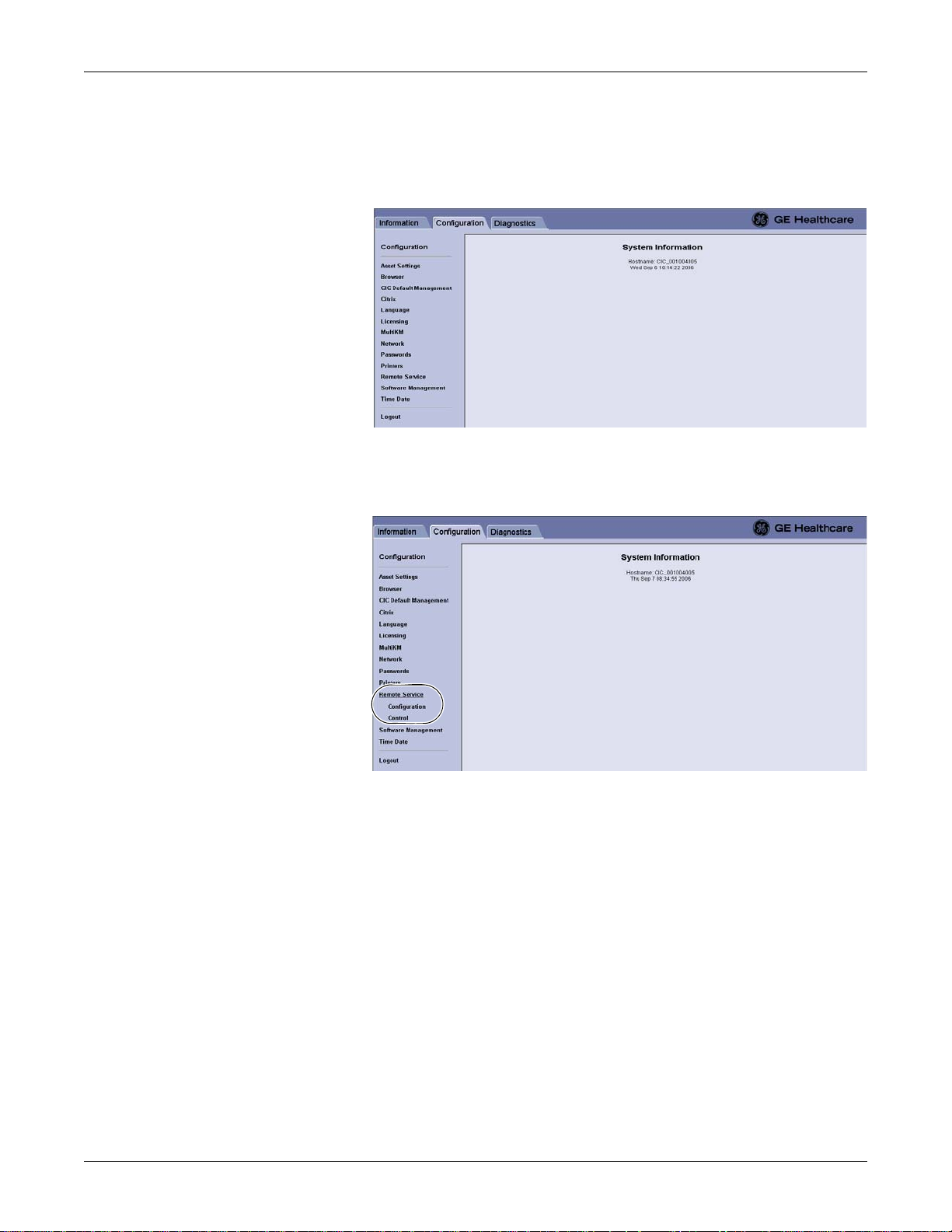
Configuration: Configuring for Remote Service access
Display the Remote Service window
1. From the Webmin application window, click Configuration. The
Configuration window displays.
2. From the Configuration window, click the Remote Service link. The Remote
Service links display.
608B
637B
View the Remote Service > Configuration data
Complete the following procedure to view the Remote Service > Configuration
data:
Under Remote Service, click the Configuration link. The Remote Service
2026419-002D CIC ProTM Clinical Information Center 4-25

Configuration: Configuring for Remote Service access
Configuration window displays.
The following table summarizes the Remote Service Configuration data fields:
Remote Service Configuration settings
638B
Item Description Comments
HTTP Proxy Server Configuration
Address
Port
Username and Password
Scheme
If this site uses an HTTP proxy server,
a specific site proxy server IP Address
and Port number are required for the
Remote Service communication to
work. Otherwise, None is selected.
If the HTTP proxy server requires user
authorization, a specific Username,
Password, and authorization Scheme
(e.g., Basic, Digest, or NTLM) is
required. Otherwise, None is selected.
Remote Service Configuration
System ID Identify the system to the GE backoffice
servers.
Serial Number Identify the unit and is determined at the
time of manufacture.
Enterprise URL Designate the address of the GE
backoffice servers required to
communicate with the Remote Service
Agent.
Enterprise Tunnel URL Designate the address of the GE
backoffice servers required to
communicate with the tunneling agent.
These values are determined
during the site survey. See the site
survey workbook.
These values are read-only and
are unique.
This address should never be
changed unless explicit
instructions are given to do so.
4-26 CIC ProTM Clinical Information Center 2026419-002D

Configuration: Setting up a Citrix client
Remote Service Configuration settings
Item Description Comments
Protocol Designate the protocol required to
communicate with the enterprise servers.
Remote Desktop Enable a remote screen-sharing for a GE
Technical Support view of the two clinical
displays for diagnosing problems with the
CIC Pro center or Unity Network.
Enable or disable the Remote Service Agent
After a GE Field Engineer (FE) has configured your CIC Pro center for remote
serviceability, this option must be enabled for use.
Complete the following procedure to enable or disable the Remote Service Agent:
1. Under Remote Service, click Control. The Remote Service Controls window
displays.
This field is read-only and cannot
be changed.
This is a view-only option. If No is
selected, then GE Technical
Support will not be able to view.
639B
2. Under Remote Service Controls, complete one of the following tasks:
To enable the Remote Service Agent, click Enable.
To disable the Remote Service Agent, click Disable.
3. Click Save to save your changes.
Setting up a Citrix client
When your facility supports a Citrix server, you can set up a Citrix client on the CIC
Pro center.
This sections describes the procedures required to set up a Citrix client:
“Log on to the Webmin service interface”
“Display the Citrix window”
2026419-002D CIC ProTM Clinical Information Center 4-27
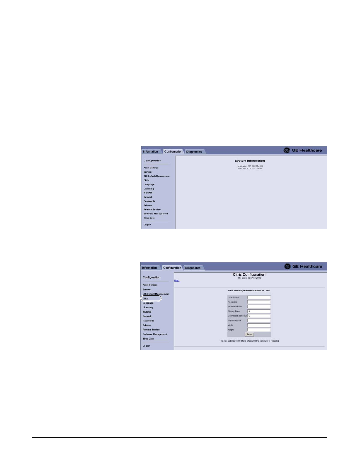
Configuration: Setting up a Citrix client
“Enter the Citrix configuration info rm ation”
Log on to the Webmin service interface
If not already logged on to the Webmin service interface, see “Log on to the local
Webmin service interface” on page 5-6 or “Log on to the remot e We bmin service
interface” on page 5-6.
Display the Citrix window
1. From the Webmin application window, click Configuration. The
Configuration window displays.
2. From the Configuration window, click the Citrix link. The Citrix
Configuration window displays.
Enter the Citrix configuration information
1. Get the Citrix configuration information for the Citrix server from the hospital’s
information technologies (IT) or biomedical engineering department.
608B
615B
2. From the Citrix Configuration window, type the applicable information into
the displayed data fields.
4-28 CIC ProTM Clinical Information Center 2026419-002D

Configuration: Browser Configuration
3. In the width and height fields, type an appropriate numeric value to define the
display size of the Citrix application window:
The approximate width x height default settings for a full-page application
(on a secondary display) is 1280 x 900.
The approximate width x height default settings for a half-page application
is 1280 x 280.
NOTE
When you define both the width and height values for the displayed
Citrix application window, scroll bars allow you to move through the
displayed information.
Scroll bars are not provided in the Citrix application window unless
you enter numeric values for both the width and the height fields.
When you leave the width and height fields empty, the Citrix
application automatically resizes itself to fit the default page size of the
CIC Pro center.
4. Click Save. Your changes will not take affect until the CIC Pro center is
rebooted.
Browser Configuration
This section describes the procedures required to set up, configure the Internet
browser and add or delete browser favorites on the CIC Pro center.
Configure the CIC Pro center’s internet connection properties
Before you set up your initial Browser favorite, you must first configure the CIC Pro
center’s internet connection properties.
This section describes the procedures required to configure the CIC Pro center’s
internet connection properties:
“Log on to the Service mode service interface”.
“Display the Browser window”.
“Configure the Internet Properties”.
Log on to the Service mode service interface
See “Log on to the Service mode” on page 5-5.
WARNING
QUALIFIED PERSONNEL — The service mode is intended for
use only by qualified personnel with training and experience in its
use. The consequences of misuse include loss of alarm
configuration, loss of patient data, corruption of the CIC Pro
center operating system software, or disruption of the entire Unity
Network.
2026419-002D CIC ProTM Clinical Information Center 4-29

Display the Browser window
Configuration: Browser Configuration
1. From the Multi-patient viewer, click Browser. The Browser window displays.
641A
The following table identifies the icons you click to navigate the Browser.
window:
Icon Description
Back navigation button.
Return to previous (cached) webpage.
Forward navigation button.
Advance to next (cached) webpage.
Stop button.
Stop the webpage loading process.
Reload button.
Reload the current webpage.
Home button.
Go to the home webpage. To set a home page, see “Browser
Configuration” on page 4-29.
Print button.
Print the current webpage.
Internet properties button.
Configure the internet options for the CIC Pro center.
Favorites button.
View the list of webpage shortcuts (favorites) displayed on the
right side of the browser. To change the list of displayed
favorites, see “Browser Configuration” on page 4-29.
4-30 CIC ProTM Clinical Information Center 2026419-002D

Configuration: Browser Configuration
Configure the Internet Properties
1. From the Browser window, double-click the (internet properties) icon to
display the Internet Properties window.
WARNING
LOSS OF MONITORING — If the browser funct i o n is
inappropriately used, loss of monitoring function may result. Use
alternate monitoring devices or close patient observation until the
monitoring function at the CIC Pro center is restored.
When using the browser, follow these restrictions:
Do NOT attempt to access the file systems of the CIC Pro
center through the use of the browser.
Do NOT attempt to download files of any type. This includes,
but is not limited to, audio or video files.
NOTE
The internet options icon will not be selectable unless you first log on to the
CIC Pro center in the Service mode.
2. In the Address field, in the Home Page section enter the internet address you
want for your browser home page, or select Use Blank. Click OK.
NOTE
When Internet Explorer starts, the browser displays the specified Home
Page.
3. Enter the Automatic configuration script or Proxy server address and port
according to the hospital IT Administrator. Click OK
2026419-002D CIC ProTM Clinical Information Center 4-31

Configuration: Browser Configuration
NOTE
Before the browser can access internet web addresses (external to the
hospital network), a connection for the Unity Network IX network to the
internet is required. Contact the hospital IT Administrator.
4. Click the Connections tab. The Connections window displays.
642A
5. Under Local Area Network (LAN) settings, click LAN Settings... The Local
Area Network (LAN) settings window displays. Then, enter the Automatic
configuration script or the Proxy server address.
NOTE
Before you can access internet or intranet web addresses, you must contact
the hospital’s IT department.
6. Under Automatic Configuration, deselect (click to remove the check mark
from the check box) the Automatically detect settings and Use automatic
configuration script options.
7. Click OK to close the Local Area Network (LAN) settings window.
8. Click OK again to close the Internet Properties window.
4-32 CIC ProTM Clinical Information Center 2026419-002D

Configuration: Browser Configuration
Adding or deleting a browser favorite
This section describes the procedures required to add or delete a browser favorite:
“Log on to the Webmin service interface”.
“Display the Browser window”.
“Add a browser favorite”.
“Delete a browser favorite”.
Log on to the Webmin service interface
If not already logged on to the Webmin service interface, see “Log on to the local
Webmin service interface” on page 5-6 or “Log on to the remot e We bmin service
interface” on page 5-6.
Display the Browser window
1. From the Webmin application window, click Configuration. The
Configuration displays.
608B
2. From the Configuration window, click the Browser link. The Browser window
displays.
623B
2026419-002D CIC ProTM Clinical Information Center 4-33

Configuration: Configuring the clinical application, telemetry, and care unit settings
Add a browser favorite
Complete the following procedure to add a browser favorite:
1. Under Please enter a name for this favorite, type the name that will identi fy
this website in the browser’s Favorites menu.
2. Under Please enter an IP address or URL (webpage address), type the internet
address (IP address) of this website.
3. Under Please select a favorite type, click to fill the radio button next to the type
of browser favorite this is.
4. If necessary, click Reset to clear the fields and selections in this window and
start again.
5. Click Create Favorite. A message similar to the following displays:
624A
6. Click the link to test the URL of this website.
7. Click Logout to log out of the Webmin service interface.
Delete a browser favorite
Complete the following procedure to delete a browser favorite:
1. From the Browser window, right-click on the favorite link you want to delete.
2. Click Delete. A Confirm File Delete message displays.
3. Click Yes to delete this browser favorite.
Configuring the clinical application, telemetry, and care unit settings
This section describes the procedures required to configure the clinical application,
telemetry, and care unit settings protected by the Service mode password:
“Display the CIC Setup window and menu”.
“Log on to the Service mode service interface”.
“Configure the CIC Defaults settings”.
“Configure the Telemetry Unit Defaults Settings”.
“Set the Full Disclosure Defaults”.
“Set the Display Configuration”.
“Set the Current Telemetry Listings”.
4-34 CIC ProTM Clinical Information Center 2026419-002D
 Loading...