

Page 1
GE
Appliances
GE Window Type Air Conditioner
AEE07KP, AED07KP,AEE09KP, AED09KP,AEE12KP,
AED12KP,AEE18KP,
Service Manual
AEE24KP,
Page 2

Service Manual
Table of Contents
Summary and Features ....................................................... 1
1. Safety Precautions .......................................................... 2
2. Specications .................................................................. 3
3. Construction Views ....................................................... 13
4. Refrigerant System Diagram ........................................ 15
5. Schematic Diagram ....................................................... 16
5.1 Electrical Data .......................................................................................................... 16
5.2 Electrical Wiring ........................................................................................................ 16
5.3 Printed Circuit Board ................................................................................................ 18
6. Function and Control .................................................... 19
6.1 Remote Control Operations ...................................................................................... 19
6.2 Description of Each Control Operation ..................................................................... 31
7. Installation Instructions ................................................ 35
8. Exploded Views and Parts List .................................... 37
9. Troubleshooting ............................................................ 58
10. Removal Procedure ..................................................... 62
Appendix: ........................................................................... 68
Appendix 1: Reference Sheet of Celsius and Fahrenheit ............................................... 68
Appendix 2: List of Resistance for Temperature Sensor ................................................ 69
Table of Contents
Page 3
Service Manual
Summary and Features
AEE07KP AEE09KP AEE12KP
AEE18KP AEE24KP
YK4EB
AED07KP
AED09KP
AED12KP
YS1FA YX1F
MODE
FAN
ON/OFF
-
+
CLOCK
TIMER OFF
TIMER ON
LIGHT
ENERGY
SAVER
SLEEP
T-ON T-OFF
AUTO
COOL
DRY
FAN
HEAT
ON/OFF
_
FAN SWING
SLEEP
SWING
SLEEP
LOCK
SPEED
MODE
+
TIMER
Technical Information
Model Remote control
AEE07KP
AEE09KP
AEE12KP
YK4EB(MC)
AEE18KP
AEE24KP
AED07KP
AED09KP
YS1FA
AED12KP YX1F
1
Page 4
1. Safety Precautions
Installing, starting up, and servicing air conditioner can be
A
according to local regulations and the instructions given in
this manual.
electric shock, explosion or injury.
.
A large enough opening for the air conditioner. Installation
Service Manual
hazardous due to system pressure, electrical components,
and equipment location, etc.
Only trained, qualified installers and service personnel are
allowed to install, start-up, and service this equipment.
Untrained personnel can perform basic maintenance functions such as cleaning coils. All other operations should
be performed by trained service personnel.
When handling the equipment, observe precautions in the
manual and on tags, stickers, and labels attached to the
equipment. Follow all safety codes. Wear safety glasses
andwork gloves. Keep quenching cloth and fire extinguisher
nearby when brazing.
Read the instructions thoroughly and follow all warnings or
cautions in literature and attached to the unit. Consult local
building codes and current editions of national as well as
local electrical codes.
Recognize the following safety information:
Warning
Caution
Incorrect handling could result in
personal injury or death.
Incorrect handling may result in
minor injury,or damage to product
or property.
parts are supplied for double-hung windows.
Make sure the ceiling/wall is strong enough to bear the
weight of the unit.
Adequate wall support for weight of air conditioner.
Follow all the installation instructions to minimize the risk
of damage from earthquakes, typhoons or strong winds.
Avoid contact between refrigerant and fire as it generates
poisonous gas.
Apply specified refrigerant only. Never have it mixed with
any other refrigerant. Never have air remain in the
refrigerant line as it may lead to rupture and other hazards
Make sure no refrigerant gas is leaking out when installation is completed.
Should there be refrigerant leakage, the density of refrigerant in the air shall in no way exceed its limited value,
or it may lead to explosion.
Keep your fingers and clothing away from any moving
parts.
Clear the site after installation. Make sure no foreign objects are left in the unit.
Always ensure effective grounding for the unit.
Warning
ll electric work must be performed by a licensed technician
Before installing, modifying, or servicing system, main
electrical disconnect switch must be in the OFF position.
There may be more than 1 disconnect switch. Lock out
and tag switch with a suitable warning label.
Never supply power to the unit unless all wiring and tubing are completed, reconnected and checked.
This system adopts highly dangerous electrical voltage.
Incorrect connection or inadequate grounding can cause
personal injury or death. Stick to the wiring diagram and
all the instructions when wiring.
Have the unit adequately grounded in accordance with
local electrical codes.
Have all wiring connected tightly. Loose connection may
lead to overheating and a possible fire hazard.
All installation or repair work shall be performed by your dealer or a specialized subcontractor as there is the risk of fire,
Caution
Never install the unit in a place where a combustible gas
might leak, or it may lead to fire or explosion.
Make a proper provision against noise when the unit is
installed at a telecommunication center or hospital.
Provide an electric leak breaker when it is installed in a
watery place.
Never wash the unit with water.
Handle unit transportation with care. The unit should not
be carried by only one person if it is more than 20kg.
Never touch the heat exchanger fins with bare hands.
Never touch the compressor or refrigerant piping without
wearing glove.
Do not have the unit operate without air filter.
Should any emergency occur, stop the unit and disconnect the power immediately.
Properly insulate any tubing running inside the room to
prevent the water from damaging the wall.
2
Technical Information
Page 5
Service Manual
2. Specications
Parameter Unit Value
Model AEE07KP AEE09KP
Product Code CC052005800_K93320 CC052005900_K93320
Power
Supply
Cooling Capacity W 1950 2640
Heating Capacity W / /
Cooling Power Input W 680 920
Heating Power Input W / /
Cooling Power Current A 3.2 4.3
Heating Power Current A / /
Rated Input W 900 1100
Rated Current A 4.86 5.95
Air Flow Volume (H/M/L) m3/h 350/300/250 480/430/380
Dehumidifying Volume L/h 0.6 1
EER W/W 2.86 2.86
COP W/W / /
Application Area m
Climate Type T1 T1
Isolation I I
Moisture Protection IP24 IP24
Permissible Excessive Operating Pressure for
the Discharge Side
Permissible Excessive Operating Pressure for
the Suction Side
Dimension (WXHXD) mm 450X350X580 560X375X618
Dimension of Carton Box (LXWXH) mm 668X518X359 727X661X463
Dimension of Package (LXWXH) mm 671X521X374 730X664X478
Net Weight kg 31 42
Gross Weight kg 34 46
Refrigerant R22 R22
Refrigerant Charge kg 0.55 0.48
Rated Voltage V~ 220 220
Rated Frequency Hz 60 60
Phases 1 1
2
MPa 3 3
MPa 1.5 1.5
7-12 12-18
Technical Information
3
Page 6
Indoor
Side
Outdoor
Side
Service Manual
Fan Type Centrifugal Centrifugal
Fan Diameter Length (DXL) mm Φ180X85 Φ205.5X111
Cooling Speed (H/M/L) r/min 1110/1010/820 920/820/720
Heating Speed (H/M/L) r/min / /
Fan Motor Power Output W 45 88
Fan Motor RLA A 0.4 0.4
Fan Motor Capacitor μF 3.5 4
Electric Heating Power Input W / /
Evaporator Form Aluminum Fin-copper Tube Aluminum Fin-copper Tube
Evaporator Pipe Diameter mm Φ7 Φ7
Evaporator Row-n Gap mm 3-1.3 3-1.5
Evaporator Coil Length (LXDXW) mm 285.7X38.1X246 330X38.1X323.9
Swing Motor Model MP24VA MP24VA
Swing Motor Power Output W 2.5 2.5
Fuse Current A 3.15 3.15
Sound Pressure Level (H/M/L) dB (A) 50/48/46 50/48/46
Sound Power Level (H/M/L)
Compressor Manufacturer
dB (A)
60/58/56
Air Conditioning Compressor
Divison(Tianjin) LG Electronics
Inc.
60/58/56
PANASONIC WANBAO
COMPRESSOR (GUANG ZHOU)
CO.LTD,
Compressor Model QA102KAD 2P14S236A1G
Compressor Oil RB68EP/FVC68D ATMOS NM56M
Compressor Type Rotary Rotary
Compressor LRA A 16 26
Compressor RLA A 3 3.8
Compressor Power Input W 662 845
Compressor Overload Protector
MRA12060-12026 or B128-150-
241E
MRA99027-9201
Throttling Method Capillary Capillary
Set Temperature Range
Cooling Operation Ambient
Temperature Range
Heating Operation Ambient
Temperature Range
O
C 16~30 16~30
O
C 18~45 18~45
O
C / /
Condenser Form Aluminum Fin-copper Tube Aluminum Fin-copper Tube
Condenser Pipe Diameter mm Φ7 Φ7
Condenser Rows-n Gap mm 3-1.6 2-1.3
Condenser Coil Length (LXDXW) mm 364X38.1X331 472X25.4X343
Fan Motor Speed (H/M/L) rpm 1110/1010/820 920/820/720
Fan Motor Power Output W 45 88
Fan Motor RLA A 0.4 0.4
Fan Motor Capacitor μF 3.5 4
Outdoor Unit Air Flow Volume m3/h 600 850
Fan Type Axial-ow Axial-ow
Fan Diameter mm Φ310 Φ353
Sound Pressure Level (H/M/L) dB (A) 58/56/54 58/56/54
Sound Power Level (H/M/L) dB (A) 68/66/64 68/66/64
Defrosting Method / /
The above data is subject to change without notice. Please refer to the nameplate of the unit.
4
Technical Information
Page 7
Service Manual
Parameter Unit Value
Model AEE12KP AEE18KP
Product Code CC052006000_K93320 CC052006100_K93320
Power
Supply
Rated Voltage V~ 220 220
Rated Frequency Hz 60 60
Phases 1 1
Cooling Capacity W 3420 5000
Heating Capacity W / /
Cooling Power Input W 1230 1800
Heating Power Input W / /
Cooling Power Current A 5.7 8.4
Heating Power Current A / /
Rated Input W 1600 2300
Rated Current A 8.65 12.43
Air Flow Volume (H/M/L) m3/h 560/510/460 940/890/840
Dehumidifying Volume L/h 1.3 2.2
EER W/W 2.78 2.78
COP W/W / /
Application Area m
2
16-24 23-34
Climate Type T1 T1
Isolation I I
Moisture Protection IP24 IP24
Permissible Excessive Operating Pressure for
the Discharge Side
Permissible Excessive Operating Pressure for
the Suction Side
Dimension (WXHXD)
MPa 3 3
MPa 1.5 1.5
mm 560X375X618 660X428X770
Dimension of Carton Box (LXWXH) mm 727X661X463 736X860X500
Dimension of Package (LXWXH) mm 730X664X478 739X863X515
Net Weight kg 49 59
Gross Weight kg 53 64
Refrigerant R22 R22
Refrigerant Charge kg 0.7 0.91
Technical Information
5
Page 8
Indoor
Side
Outdoor
Side
Service Manual
Fan Type Centrifugal Centrifugal
Fan Diameter Length (DXL) mm Φ205.5X111 Φ224X109.5
Cooling Speed (H/M/L) r/min 1100/960/820 1000/900/800
Heating Speed (H/M/L) r/min / /
Fan Motor Power Output W 100 155
Fan Motor RLA A 0.4 0.8
Fan Motor Capacitor μF 4 7
Electric Heating Power Input W / /
Evaporator Form Aluminum Fin-copper Tube Aluminum Fin-copper Tube
Evaporator Pipe Diameter mm Φ7 Φ7
Evaporator Row-n Gap mm 3-1.5 2-1.3
Evaporator Coil Length (LXDXW) mm 330X38.1X323.9 392X25.4X381
Swing Motor Model MP24VA MP28ED
Swing Motor Power Output W 2.5 2
Fuse Current A 3.15 3.15
Sound Pressure Level (H/M/L) dB (A) 54/52/50 57/55/53
Sound Power Level (H/M/L) dB (A) 64/62/60 67/65/63
Compressor Manufacturer
Air Conditioning Compressor
Divison(Tianjin) LG Electronics
Inc.
Air Conditioning Compressor
Divison(Tianjin) LG Electronics
Inc.
Compressor Model QK173KAB QJ250KBF
Compressor Oil NM56M NM56M
Compressor Type Rotary Rotary
Compressor LRA A 29 42
Compressor RLA A 5.6 7.5
Compressor Power Input W 1141 1606
Compressor Overload Protector
MRA98996-12026/B195-140-
241E/KA-122-LLBN17B
MRA12107-12027/B273-150-
141E
Throttling Method Capillary Capillary
Set Temperature Range
Cooling Operation Ambient
Temperature Range
Heating Operation Ambient
Temperature Range
O
C 16~30 16~30
O
C 18~45 18~45
O
C / /
Condenser Form Aluminum Fin-copper Tube Aluminum Fin-copper Tube
Condenser Pipe Diameter mm Φ7 Φ7
Condenser Rows-n Gap mm 3-1.4 2-1.3
Condenser Coil Length (LXDXW) mm 472X38.1X343 885X25.4X400
Fan Motor Speed (H/M/L) rpm 1100/960/820 1000/900/800
Fan Motor Power Output W 100 155
Fan Motor RLA A 0.4 0.8
Fan Motor Capacitor μF 4 7
Outdoor Unit Air Flow Volume m3/h 880 1670
Fan Type Axial-ow Axial-ow
Fan Diameter mm Φ353 Φ396
Sound Pressure Level (H/M/L) dB (A) 61/59/57 62/60/58
Sound Power Level (H/M/L) dB (A) 71/69/67 72/70/68
Defrosting Method / /
The above data is subject to change without notice. Please refer to the nameplate of the unit.
6
Technical Information
Page 9
Service Manual
Parameter Unit Value
Model AEE24KP
Product Code CC052006200_K93320
Power
Supply
Rated Voltage V~ 220
Rated Frequency Hz 60
Phases 1
Cooling Capacity W 6530
Heating Capacity W /
Cooling Power Input W 2350
Heating Power Input W /
Cooling Power Current A 10.8
Heating Power Current A /
Rated Input W 2700
Rated Current A 14.59
Air Flow Volume (H/M/L) m3/h 940/890/840
Dehumidifying Volume L/h 2.8
EER W/W 2.78
COP W/W /
Application Area m
2
27-42
Climate Type T1
Isolation I
Moisture Protection IP24
Permissible Excessive Operating Pressure for
the Discharge Side
Permissible Excessive Operating Pressure for
the Suction Side
Dimension (WXHXD)
MPa 3
MPa 1.5
mm 660X428X770
Dimension of Carton Box (LXWXH) mm 736X860X500
Dimension of Package (LXWXH) mm 739X863X515
Net Weight kg 68
Gross Weight kg 73
Refrigerant R22
Refrigerant Charge kg 1.4
Technical Information
7
Page 10
Indoor
Side
Outdoor
Side
Fan Type Centrifugal
Fan Diameter Length (DXL) mm Φ224X109.5
Cooling Speed (H/M/L) r/min 1060/970/820
Heating Speed (H/M/L) r/min /
Fan Motor Power Output W 200
Fan Motor RLA A 0.8
Fan Motor Capacitor μF 7
Electric Heating Power Input W /
Evaporator Form Aluminum Fin-copper Tube
Evaporator Pipe Diameter mm Φ7
Evaporator Row-n Gap mm 3-1.6
Evaporator Coil Length (LXDXW) mm 392X38.1X381
Swing Motor Model MP28ED
Swing Motor Power Output W 2
Fuse Current A 3.15
Sound Pressure Level (H/M/L) dB (A) 57/55/53
Sound Power Level (H/M/L)
dB (A)
67/65/63
Compressor Manufacturer ZHUHAI LANDA COMPRESSOR CO., LTD
Compressor Model QX-F325rF090
Compressor Oil ATMOS NM56EP
Compressor Type Rotary
Compressor LRA A 59
Compressor RLA A 10.5
Compressor Power Input W 2200
Compressor Overload Protector UP14QE5345-M
Throttling Method Capillary
Set Temperature Range
Cooling Operation Ambient
Temperature Range
Heating Operation Ambient
Temperature Range
O
C 16~30
O
C 18~45
O
C /
Condenser Form Aluminum Fin-copper Tube
Condenser Pipe Diameter mm Φ7
Condenser Rows-n Gap mm 3-1.6
Condenser Coil Length (LXDXW) mm 885X38.1X400
Fan Motor Speed (H/M/L) rpm 1060/970/820
Fan Motor Power Output W 200
Fan Motor RLA A 0.8
Fan Motor Capacitor μF 7
Outdoor Unit Air Flow Volume m3/h 1670
Fan Type Axial-ow
Fan Diameter mm Φ396
Sound Pressure Level (H/M/L) dB (A) 62/60/58
Sound Power Level (H/M/L) dB (A) 72/70/68
Defrosting Method /
Service Manual
The above data is subject to change without notice. Please refer to the nameplate of the unit.
8
Technical Information
Page 11
Service Manual
Parameter Unit Value
Model AED07KP AED09KP
Product Code CC052024200_K93412 CC052024300_K93412
Power
Supply
Rated Voltage V~ 220 220
Rated Frequency Hz 60 60
Phases 1 1
Cooling Capacity W 2110 2720
Heating Capacity W / /
Cooling Power Input W 650 840
Heating Power Input W / /
Cooling Power Current A 3 3.9
Heating Power Current A / /
Rated Input W 900 1000
Rated Current A 4.86 5.41
Air Flow Volume (H/M/L) m3/h 480/430/380 480/430/380
Dehumidifying Volume L/h 0.6 1
EER W/W 3.22 3.22
COP W/W / /
Application Area m
2
7-12 12-18
Climate Type T1 T1
Isolation I I
Moisture Protection IP24 IP24
Permissible Excessive Operating Pressure for
the Discharge Side
Permissible Excessive Operating Pressure for
the Suction Side
Dimension (WXHXD)
MPa 3 3
MPa 1.5 1.5
mm 560X375X668 560X375X668
Dimension of Carton Box (LXWXH) mm 763X620X410 763X620X410
Dimension of Package (LXWXH) mm 766X623X425 766X623X425
Net Weight kg 39 45
Gross Weight kg 43 49
Refrigerant R22 R22
Refrigerant Charge kg 0.5 0.7
Technical Information
9
Page 12
Indoor
Side
Outdoor
Side
Service Manual
Fan Type Centrifugal Centrifugal
Fan Diameter Length (DXL) mm Φ205.5X111 Φ205.5X111
Cooling Speed (H/M/L) r/min 950/880/780 950/880/780
Heating Speed (H/M/L) r/min / /
Fan Motor Power Output W 60 60
Fan Motor RLA A 0.5 0.5
Fan Motor Capacitor μF 4 4
Electric Heating Power Input W / /
Evaporator Form Alumium Tube Alumium Tube
Evaporator Pipe Diameter mm Φ7 Φ7
Evaporator Row-n Gap mm 2-1.3 3-1.5
Evaporator Coil Length (LXDXW) mm 330X25.4X323.9 330X38.1X323.9
Swing Motor Model MP24VA MP24VA
Swing Motor Power Output W 1.5 1.5
Fuse Current A 3.15 3.15
Sound Pressure Level (H/M/L) dB (A) 50/48/46 50/48/46
Sound Power Level (H/M/L)
Compressor Manufacturer
dB (A)
60/58/56
Air Conditioning Compressor
Divison(Tianjin) LG Electronics
Inc.
60/58/56
PANASONIC WANBAO
COMPRESSOR (GUANG ZHOU)
CO.LTD,
Compressor Model QA102KAD 2P14S236A1G
Compressor Oil RB68EP/FVC68D ATMOS NM56M
Compressor Type Rotary Rotary
Compressor LRA A 16 26
Compressor RLA A 3 3.8
Compressor Power Input W 662 845
Compressor Overload Protector
MRA12060-12026 or B128-150-
241E
MRA99027-9201
Throttling Method Capillary Capillary
Set Temperature Range
Cooling Operation Ambient
Temperature Range
Heating Operation Ambient
Temperature Range
O
C 16~30 16~30
O
C 18~43 18~43
O
C / /
Condenser Form Aluminum Fin-copper Tube Aluminum Fin-copper Tube
Condenser Pipe Diameter mm Φ7 Φ7
Condenser Rows-n Gap mm 2-1.4 2-1.4
Condenser Coil Length (LXDXW) mm 597X25.4X342.9 597X25.4X342.9
Fan Motor Speed (H/M/L) rpm 950/880/780 950/880/780
Fan Motor Power Output W 60 60
Fan Motor RLA A 0.5 0.5
Fan Motor Capacitor μF 4 4
Outdoor Unit Air Flow Volume m3/h 850 850
Fan Type Axial-ow Axial-ow
Fan Diameter mm Φ353 Φ353
Sound Pressure Level (H/M/L) dB (A) 58/56/54 58/56/54
Sound Power Level (H/M/L) dB (A) 68/66/64 68/66/64
Defrosting Method / /
The above data is subject to change without notice. Please refer to the nameplate of the unit.
10
Technical Information
Page 13
Service Manual
Parameter Unit Value
Model AED12KP
Product Code CC052024400_K93412
Power
Supply
Rated Voltage V~ 220
Rated Frequency Hz 60
Phases 1
Cooling Capacity W 3480
Heating Capacity W /
Cooling Power Input W 1090
Heating Power Input W /
Cooling Power Current A 5
Heating Power Current A /
Rated Input W 1400
Rated Current A 7.57
Air Flow Volume (H/M/L) m3/h 760/710/660
Dehumidifying Volume L/h 1.3
EER W/W 3.19266055
COP W/W /
Application Area m
2
Climate Type T1
Isolation I
Moisture Protection IP24
Permissible Excessive Operating Pressure for
the Discharge Side
Permissible Excessive Operating Pressure for
the Suction Side
Dimension (WXHXD)
MPa 3
MPa 1.5
mm 660X428X700
Dimension of Carton Box (LXWXH) mm 790X736X500
Dimension of Package (LXWXH) mm 793X739X515
Net Weight kg 52
Gross Weight kg 57
Refrigerant R22
Refrigerant Charge kg 0.68
16-24
Technical Information
11
Page 14
Indoor
Side
Outdoor
Side
Service Manual
Fan Type Centrifugal
Fan Diameter Length (DXL) mm Φ201.5X109.5
Cooling Speed (H/M/L) r/min 900/780/730
Heating Speed (H/M/L) r/min /
Fan Motor Power Output W 100
Fan Motor RLA A 0.8
Fan Motor Capacitor μF 7
Electric Heating Power Input W /
Evaporator Form Alumium Tube
Evaporator Pipe Diameter mm Φ7
Evaporator Row-n Gap mm 3-1.6
Evaporator Coil Length (LXDXW) mm 392X38.1X381
Swing Motor Model MP28ED
Swing Motor Power Output W 2
Fuse Current A 3.15
Sound Pressure Level (H/M/L) dB (A) 57/55/53
Sound Power Level (H/M/L)
dB (A)
67/65/63
Compressor Manufacturer Air Conditioning Compressor Divison(Tianjin) LG Electronics Inc.
Compressor Model QK164KBD
Compressor Oil SUNISO 4GSI
Compressor Type Rotary
Compressor LRA A 24
Compressor RLA A 5.07
Compressor Power Input W 1060
Compressor Overload Protector MRA12124-12026
Throttling Method Capillary
Set Temperature Range
Cooling Operation Ambient
Temperature Range
Heating Operation Ambient
Temperature Range
O
C 16~30
O
C 18~43
O
C /
Condenser Form Aluminum Fin-copper Tube
Condenser Pipe Diameter mm Φ7
Condenser Rows-n Gap mm 3-1.4
Condenser Coil Length (LXDXW) mm 665X38.1X400
Fan Motor Speed (H/M/L) rpm 900/780/730
Fan Motor Power Output W 100
Fan Motor RLA A 0.8
Fan Motor Capacitor μF 7
Outdoor Unit Air Flow Volume m3/h 1300
Fan Type Axial-ow
Fan Diameter mm Φ396
Sound Pressure Level (H/M/L) dB (A) 62/60/58
Sound Power Level (H/M/L) dB (A) 72/70/68
Defrosting Method /
The above data is subject to change without notice. Please refer to the nameplate of the unit.
12
Technical Information
Page 15
Service Manual
3. Construction Views
(1)Models:AEE07KP,AEE09KP,AEE12KP,AEE18KP,AEE24KP
W D
H
Over
150
Over 500
Over
150
Unit:mm
Model W H D
AEE07KP 450 350 580
AEE09KP 560 375 618
AEE12KP 560 375 618
AEE18KP 660 428 770
AEE24KP 660 428 770
Technical Information
13
Page 16
(2)Models:AED07KP,AED09KP,AED12KP
W D
Service Manual
H
Over
150
Over 500
Over
150
Unit:mm
Model W H D
AED07KP 560 375 668
AED09KP 560 375 668
AED12KP 660 428 700
14
Technical Information
Page 17
Service Manual
R
REFRIGERANT FLOW DIRECTION
CENTRIFUGAL
4. Refrigerant System Diagram
COOLED AIR
INDOOR COILS
OR CROSS FAN
AXIAL FAN
HOT DISCHARGED AI
COMPRESSOR
OUTDOOR COILS
CAPILLARY
Technical Information
15
Page 18
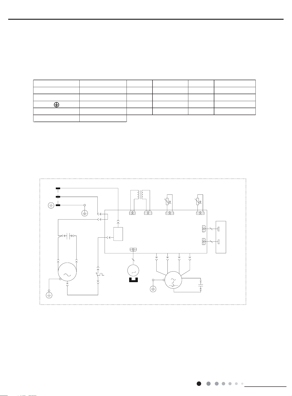
5. Schematic Diagram
BN(BK)
TRANSFORMER
FAN MOTOR
DISPLAY BOARD
TUBE TEMP.TEMP.ROOM
W4
5.1 Electrical Data
Meaning of marks
Symbol Parts name Symbol Color symbol Symbol Color symbol
SAT
COMP
C1
C2
5.2 Electrical Wiring
OVERLOAD
COMPRESSOR
PROTECTIVE EARTH
CBB65
CBB61
BU
YE
RD
YEGN
BLUE
YELLOW
RED
YELLOW GR EEN
VT
OG
BK
BN
Service Manual
VIOL ET
ORAN GE
BLACK
BROWN
(1)Models:AEE07KP, AEE09KP, AEE12KP, AED07KP,
AED09KP,AED12KP
L
BU
BU
COMP
C
PE
BU(WH)
YEGN(GN)
PE
CAP.
C1
YEW2
COMP.
W1
BK
(RD)
S
SAT
N1
TR-INTR-OUT
L
PRINTEDCIRCUIT BOARD
COMP
OVERLOAD
CN2
5
M2
SWING
PROTECTOR
MOTOR
N
POWER
W3
R(M)
YEGN
TC
BU
YEGN
AP1
FL
PE
SENSOR
TUBE
FM
YE
M1
BK
FH
WH
RD
RT2RT1
N2
SENSOR
ROOM
CN1
CN3
BN
C2
10
CAP.
7
DISPLAY
RECEIVER AND
AP2
16
Technical Information
Page 19
Service Manual
ROOM PIPE
FAN MOTOR
BN(BK)
R(M,V)
D
D
TEMP. SENSOR
ROOM TUBE
TRANSFORMER
BU(WH)
BN(BK)
(2)Model:AEE18KP
L
N
POWER
BU
BU
YEGN
PE
COMPRESSOR
(3)Model:AEE24KP
BU
PE
BU(WH)
YEGN(GN)
CAP.
C1
COMP
PE
C(T,U)
YE
S(W,X)
BK
(RD)
X107
COMP
K101
SAT
OVERLOAD
PROTECTOR
TRANSFORMER
TR-INTR-OUT
L
CN2
5
M2
STEPPING
MOTOR
TEMP. SENSOR
AP1
CONTROLLER
X113
X112
(FL)
(FM)
BU
YE
YEGN
PE
PE
TUBE
M1
BK
X114
(FH)
ROOM
CN1
CN3
WH
BN
RD
10
X4
C2
ROOM TEMP.
SENSOR
7
AP2
DISPLAY
RECEIVER AND
DISPLAY BOAR
CAP.
YEGN(GN)
PE
W7BK
5
RELAY
1
6
R(M)
C
COMP
W8BU
S
W3BU
C1
COMP.
W5BU
J
W4BU
CAP.
W2YE
X5(AC-L)
X107(N1)
COMP
PRINTEDCIRCUIT
CN2
5
M2
SWING
MOTOR
PE
TR-OUTTR-IN
AP1
X112
(FL)
YEGN
X113
(FM)
FAN
MOTOR
TUBE
BOARD
X114
(FH)
M1
ROOM
WHBU YE BK
RD
CN1
CN3
X4(N2)
BN
C2
ROOM TEMP.
SENSOR
7
AP2
DISPLAY
10
RECEIVER AND
DISPLAY BOAR
CAP.
Technical Information
These circuit diagrams are subject to change without notice, please refer to the one supplied with the unit.
17
Page 20
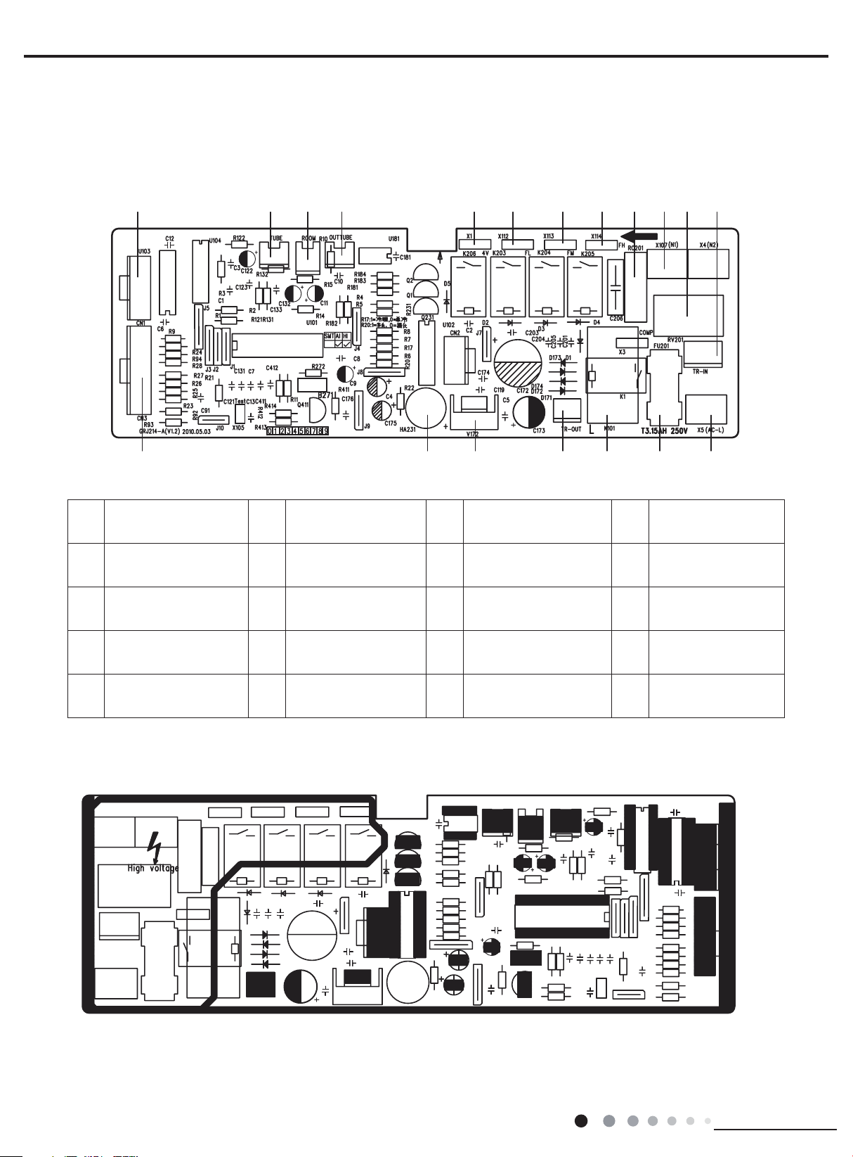
5.3 Printed Circuit Board
Main board
● TOP VIEW
Service Manual
10111415 13 12 9819 18 17 16
Board connection wire
1
interface needle
2 Buzzer 7 Live wire copper insert 12 High fan speed interface 17
3 7805 regulated block 8 Transformer input port 13
4 Transformer outlet port 9 Piezoresistance 14 Low fan speed interface 19
5 Compressor relay 10
● BOTTOM VIEW
6 Fuse 11
Neutral wire copper
insert
resistance-capacitor
module
Medium fan speed
interface
15 4-way valve interface 20 /
Outdoor tube
16
temperature sensor
Indoor ambient
temperature sensor
Indoor tube
18
temperature sensor
Board connection
wire needle interface
7654321
18
Technical Information
Page 21
Service Manual
elay ON-When the air conditioner is off,
1
n
settings.
6. Function and Control
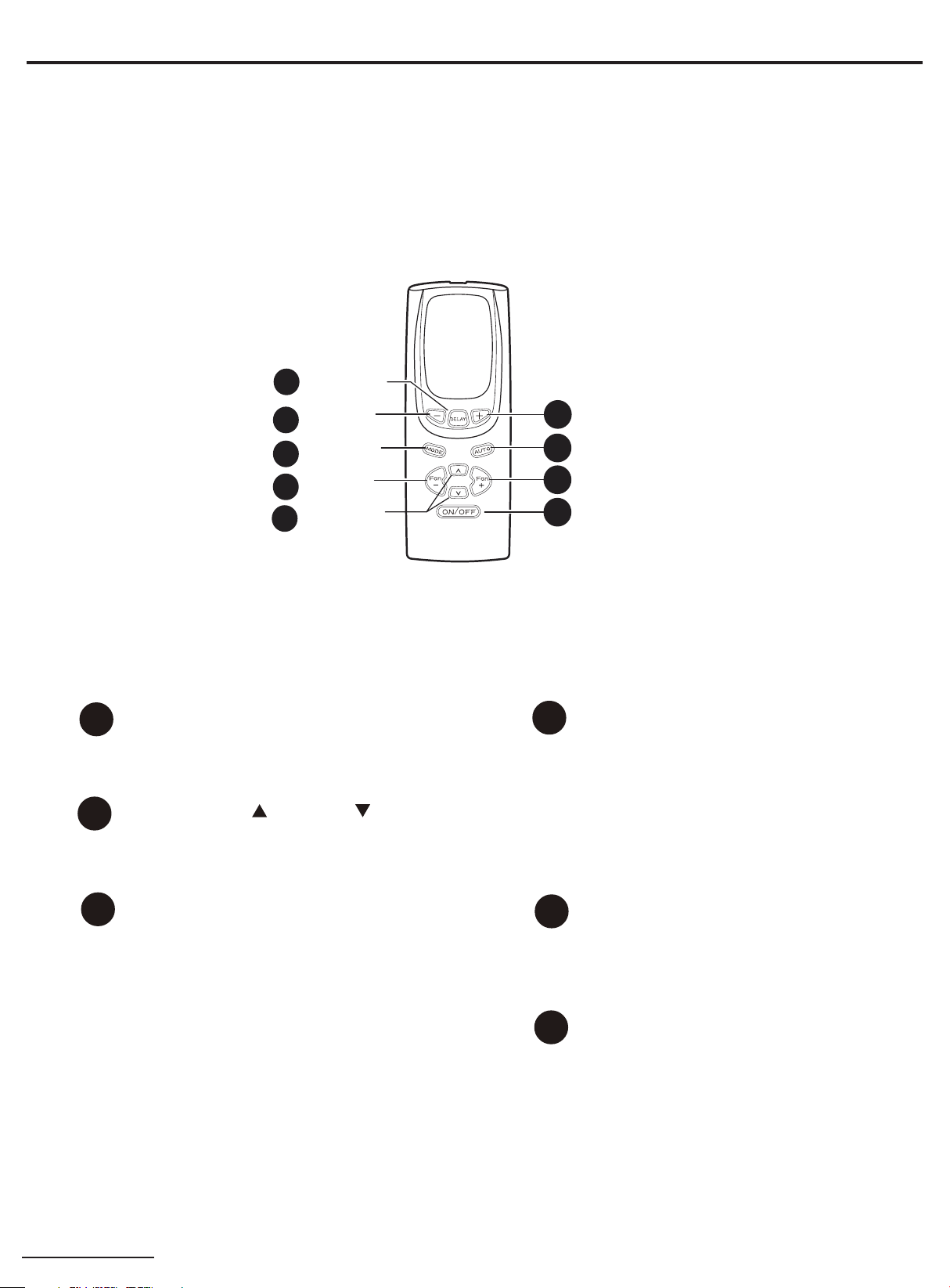
6.1 Remote Control Operations
(1)Models:YK4EB (AEE07KP,AEE09KP,AEE12KP,AEE18KP,AEE24KP)
Delay 1–24hr
6
Delay timer
3
Decrease
Mode select
5
Fan speed
4
Decrease
Temperature
2
set Increase
and Decrease
Power Pad
1
Turns air conditioner on and off.when
turned on, the display will show the rooom temperature.
Temp Increase /Decrease Pads
2
Use to set temperature when in
Cool/Energy Saver .The Set light will
turn on while setting.
Delay Timer Increase (+) /Decrease
3
(-) Pads
Each touch of the Increase / Decrease
pads on the unit or the Increase +/De-
crease - pads on the remote control will
set the delay time when using the Delay
1-24hr timer.The Set light will turn on
while setting.
Remote Control
Delay timer Increase
3
Auto Fan on
4
Fan speed Increase
4
Unit power on/off
1
Fan Speed Pads
4
Use the Fan Speed Pads on the unit to
set the fan speed to Low,Med,High or
Auto fan.NOTE: On the remote control, use
the fan speed Increase+/Decrease- pads
to set the fan speeds to Low, Med or High.
Use the Auto pad to turn Auto fan on.
Mode Pad
5
Use to set the air conditioner to Cool,
Energy Saver,Fan only mode.
Delay Pads
6
D
it can be set to automatically come on in
to 24 hours at its previous mode and fa
Technical Information
19
Page 22

Service Manual
begin.
Cooling Descriptions
Delay OFF-When the air conditioner is on,it can be
set to auto matically turn off in 1 to 24 hours.
How to set:
Press the Delay 1-24hr pad on the unit or the DELAY
pad on the remote control. Each touch of the Increase/
Decrease pads on the unit or the Increase + / De-
crease - pads on the remote control will set the timer
in 1 hour intervals.
setting.
To review the remaining time on the Delay 1-24hr
timer, press the Delay 1-24hr pad on the unit or
the DELAY pad on the remote control. Use the Increase/
Decrease pads on the unit or the Increase+/De-
crease- pads on the remote control to set a new
time if desired.
setting,press Delay 1-24hr button on the panel
or Delay button on the remote controller to cancel the timer setting.
The Set
During preview of time or timer
light will turn on while
Remote Control
To ensure proper operation, aim the remote control
at the signal receiver on the air conditioner.
The remote control signal has a range of up to 20
feet.Make sure nothing is between the air
conditioner and the remote control that could block
the signal.
Make sure batteries are fresh and installed correctly
as indicated on the remote control.
Cool Mode
Use the Cool mode at Low, Med, High or Auto Fan
Speed for cooling. Use the Temperature Increase/
Decrease pads to set the desired temperature be-
tween 64
The compressor will cycle on and off to keep the
room at the set level of comfort. Set the thermostat at
a lower number and the indoor air will become
cooler. Set the thermostat at a higher number and
the indoor air will become warmer.
NOTE: If the air conditioner is off and is then turned
on while set to a Cool setting or if turned from a fan
setting to a Cool setting, it may take approximately 3
minutes for the compressor to start and cooling to
F in 1F increments.F and 86
For Normal Cooling Select the Cool mode and
or Med fan with a middle set temperature.
For Maximum Cooling Select the Cool mode and
High
fan
& Night time Co
ow fan with a middle set
Energy Saver Mode
The fan will cycle on and off with the compressor.T-
results
his
nd humidity.
ied. NOTE:The
me after the compressor
Fan Only Mode
Use the Fan Only Mode at Low, Med or High fan sp-
eed to pr
ooling. Since fan
ing, a Set temperature can
temperature will appear in the
NOTE:Auto Fan Speed cannot be used when in the
Fan Only Mode.
Auto Fan Speed
Set to Auto fan speed for the fan speed to autom-
atically set
um comfort settings
the room needs more cooling,
automatically increase.If the room needs
NOTE:Auto Fan Speed cannot be used when in the
Fan
Only Mode.
Power Outage Recovery Feature
In the case of a power outage or interruption, the u-
automati
nit will
after the po
ure was set, it will
morized time
desired.
with a
lower set temperature. For Quieter
oling Select the
temperature.
wider variations of room temperature a-
in
Normally used
may continue to run
fan
cycles off.
ovide air
circulation and filtering without c-
only settings do
to the
speed needed to provide optim-
with the set
will automatically decrease. the fan speed
cally restart in the settings last used
wer
is restored. If
countdown
may
.You
need
Cool mode and L-
when the room is unoccup-
for a short ti-
not provide cool-
not be entered. The room
display.
temperature.If
the fan speed will
less cooling,
the Delay 1-24hr feat-
according to
set a
to
ne
w
the
time if
High
me-
20
Technical Information
Page 23
Service Manual
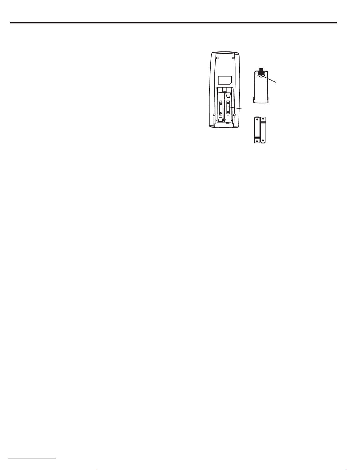
Replacement of Batteries
NOTE:
1.Don’t confuse the new and worn or different types of batteries.
2.Remove batteries when the remote controller is not in use for a long time.
3.The lifetime of the batteries is about one yea
4.The remote controller should be placed about 1m or more away from the TV
5.Bad batteries are forbidden.
Re - attach the cover.
1.Remove the cover from the back of the remote control.
2.Insert the two batteries (T
3.Re-attach the cove
wo AAA dry-cell batteries).
r.
①Remove the cover.
③
②Insert the AAA batteries.
r.
. Or any other electric appliances.
Technical Information
21
Page 24

(2)Model:YS1FA (AED07KP,AED09KP)
Name and Function of Wireless Remote Control
Note: This wireless remote control is universal,and it could be used for many
is not available under FAN or AUTO mode.
other models. The buttons that are not relevant to this unit will not be
described below.
Service Manual
Signal Transmitter
SLEEP
SLEEP button
Press SLEEP button to select sleep on
or sleep off. It is defaulted sleep off after
powering on. will be displayed once
sleep function is set on. The
Remote Control
ON/OFF
MODE
ON/OFF button
Press this button to turn on the unit,
press it again to turn off the unit.
MODE button
Press this button, AUTO,COOL,
FAN,
DRY,
selected
AUTO mode after
unit while the setting
will not be displayed.The initial
setting temperature is 28
under HEAT mode,
under other modes.
HEAt mode can be
circularly.
It is defaulted
powering on the
temperature
℃
(77 F)
℃
25
o
(82 F)
o
FAN
CLOCK
FAN button
Press this button, AUTO,LOW,MED,HIGH
speed can be circularly selected. After
powering on the unit, auto fan speed
is defaulted.Under DRY mode, only
low fan speed can be set up.
AUTO
LOW
HIGH
CLOCK button
Press this button, the clock can be set up,
blinks and displays.Within 5
seconds, the value can be adjusted by
pressing + or - button,if consecutively
press this button for more than 2 seconds,
the value will be fast increasing. Press
CLOCK again during blinking, will be
displayed
is defaulted displaying 12:00 and
after powering on.Either clock time or
timer time could be displayed.
sleep function
MED
and the clock setting is done. It
22
AUTO
COOL
DRY
FAN
HEAT
(Only available for heating unit)
SWING button
When it is pressed,the louvers start to
rotate automatically and stop when
repressed.
Technical Information
Page 25

Service Manual
Note: This wireless remote control is universal,and it could be used for many
other models. The buttons that are not relevant to this unit will not be
described below.
+
+ button
Press this button to increase setting
temperature,
to rapidly
AUTO mode,
adjustable.Setting temperature Range of
Celsius degree:
61-86
increase setting temperature.In
o
F.
-
- button
Remote Control
ENERGY
SAVER
ENERGY SAVER button
Under the COOL and DRY mode,
press
enter
this button again, the unit will exit
ENERGY SAVER mode.
LIGHT
LIGHT button
Press this button to turn ON or OFF
the light or display on the unit.
The light or display is defaulted on
after powering on
this button once, the unit will
ENERGY SAVER mode.Press
the unit.
TIMER
ON
Press this button to decrease setting
temperature,hold for more than 2 seconds
to rapidly
In AUTO mode,setting temperature is
not adjustable.
decrease setting temperature.
TIMER ON button
At unit off,press TIMER ON button,HOUR
ON will blink and display,
concealed in the TIMER ON setting.During
5 seconds blinking,the value can be
adjusted by pressing + or - button,every
press of this button,0.5hour will be increased
or decreased,by continuous pressing the +
or - button,2 seconds later,the value will be
changed quickly,0.5hour will be changed in
every 0.25second automatically by the
remote control.During blinking,press the
TIMER ON button to confirm the time.After
TIMER ON set up,with repressing the TIMER
ON button,the TIMER ON setting will be
canceled.After powered on,no timer is
defaulted, HOUR ON(OFF)will not display,
and only the clock is displayed.After the timer
reached the setting time,HOUR ON(OFF)
will conceal.Before setting the timer,please
adjust the clock to the current actual time.
hold for more than 2 seconds
setting temperature is not
16-30
,Fahrenheit degree:
℃
will be
Technical Information
TIMER
OFF
TIMER OFF button
At unit on,press TIMER OFF button to enter
into TIMER OFF setting.The method of setting
up is the same as TIMER ON.
23
Page 26

Guide for Operation -General Operation
1. After powering on,press ON/OFF button,the unit will start to run.(Note:When
At unit off,press MODE and - button simultaneously to switch between and .
it is powered on,the guide louver of indoor unit will close automatically.)
2. Press MODE button to select desired running mode.
3. Pressing + or - button, to set the desired temperature.
4. Press FAN button to set AUTO,LOW,MED or HIGH fan speed.
5. Pressing button, to select the swing.
Service Manual
Guidefor Operation - Optional Operation
1. Press SLEEP button, to set sleep.
2. Press TIMER ON and TIMER OFF button,to set the scheduled timer on
or timer off.
3. Press LIGHT button, to control the on and off of the light or display
on the unit.
4. Press ENERGY SAVER button to activate the function.
Introduction for Special Function
About AUTO mode
When AUTO mode is selected,the setting temperature will not be displayed on the
remote control,the unit will be in accordance with the room temperature,and automatically
select the suitable running method to make ambient comfortable.
About Lock
Press + and - buttons simultaneously to lock or unlock the keyboard of the remote control.
If the keyboard
three times. If the keyboard is unlocked, the will not display.
is locked, will be displayed on it,press any button, will blink
About Switch Between Fahrenheit and Centigrade
24
ć
Technical Information
Page 27

Service Manual
Changing Batteries
sunlight or any place where is very hot.
1.
Slightly press the place with
2. Take out the used batteries. (As show in figure)
3. Insert two new AAA1.5V batteries,and pay attention to the polarity.
(As show in figure)
4. Push the back cover of remote control.(As show inf figure)
,and push the cover along the arrow.
2
NOTE:
When changing the batteries, do not mix used and new batteries,
do not mix different batteries,otherwise, it can cause the malfunction
of the remote control.
Notices
If the remote control will not be used for a long time,please take out
batteries to prevent any damage from liquid leakage.
The operation should be in its receiving range.
It should be placed 1m away from the TV or stereo sound sets.
If the remote control can not work normally, please take out the
batteries,then reinsert 30S after, if it does not run normally,change the
batteries.
Be sure that there are no obstructions between receiver and remote
control,
Don't drop or throw the remote control,Don't let any liquid get
into the remote control or
1
3
4
Sketch map for
changing batteries
put the remote control directly under the
Technical Information
25
Page 28

(3)Model:YX1F(AED12KP)
Icon Display on Remote
Operation introduction of remote controll
Buttons on Remote Controller
Note:
will blink once. If the air conditioner gives out a beep sound, it means the signal has been sent.
corresponding icon will be displayed); When unit is on, it will display the icon of the on-going function.
1. ON/OFF Button
Press this button to turn unit on/of
2. MODE Button
Pressing this button once can select your required mode circularly as below(the corresponding icon
selected):
Service Manual
ON/OFF button
AUTO
COOL
DRY
FAN
HEAT
ON/OFF
T-ON T-OFF
_
FAN SWING
SLEEP
For auto operation
SWING
SLEEP
LOCK
SPEED
MODE
+
TIMER
Controller
For cooling
For drying
For fan only
For heating
Timer on Timer off
T-ON T-OFF
AUTO
COOL
DRY
FAN
HEAT
SWING
SLEEP
LOCK
SPEED
MODE button
+/- botton
FAN button
SWING button
SLEEP button
TIMER button
Sending signal
For air swing
For sleeping
For locking
For setting fan speed
Set temperature
Set time
er
When power is connected(stand by condition), you can operate the air conditioner through the remote controller.
When unit is on, each time you press the button on remote controller, the sending signal icon on the display of remote controller
When unit is off, set temperature will be displayed on the remote controller(If the light of indoor unit display is turned on, the
f.
AUTO COOL DRYFAN HEAT
26
will be lit up after the mode is
Technical Information
Page 29

Service Manual
When selecting auto mode, air conditioner will operate automatically according to ex-factory setting. Set temperature can't be
adjusted and won't be displayed either
FA
ess
FA
3. +/- butto
remote controller will change quickl
4.
Pressing this button can select fan speed circularly as:
5. SWING Butto
Press this button to turn on up&down air swing.
6. SLEEP
Under Cool, Heat, Dry mode, press this button to turn on Sleep function. Press this button to cancel Sleep function. Under Fan
A
Simple operationfi
1.After putting through power
as third notch for this air conditioner.)
. Press FAN button to adjust fan speed. (This function is not available in this air conditioner.)
When selecting cool mode, air conditioner will operate under cool mode. Then press + or -- button to adjust set temperature. Press
N button to adjust fan speed.
When selecting dry mode, air conditioner will operate at low fan speed under dry mode. In dry mode, fan speed can't be adjusted.
When selecting fan mode, air conditioner will operate in fan mode only. Then press FAN button to adjust fan speed.
When selecting heat mode, air conditioner will operate under heat mode. Then press + or -- button to adjust set temperature. Pr
N button to adjust fan speed.
Pressing + or - button once will increase or decrease set temperature by 1 °F(°C). Hold + or -- button for 2s, set temperature on
When setting Timer On, Timer Off or Clock, press + or -- button to adjust the time (See TIMER Button for setting details).
FAN Button
in this air conditioner. Speed 4 is the same with speed 3).
Note:
Under Auto mode, air conditioner will select proper fan speed automatically according to ex-factory setting.
Fan speed can't be adjusted under Dry mode.
uto mode, this function is unavailable.
7. TIMER Button
When unit is on, press this button to set Timer Off. T-OFF and H icon will be blinking. Within 5s, press + or - button to adjust the
time for Timer Off. Pressing + or - button once will increase or decrease the time by 0.5h. Hold + or - button for 2s, time will change
quickly. Release the button after your required set time is reached. Then press TIMER button to confirm it. T-OFF and H icon will
stop blinking.
When unit is off, press this button to set Timer On. T-ON and H icon will be blinking. Within 5s, press + or - button to adjust the
time for Timer On. Pressing + or - button once will increase or decrease the time by 0.5h. Hold + or - button for 2s, time will change
quickly. Release the button after your required set time is reached. Then press TIMER button to confirm it. T-ON and H icon will stop
blinking.
Cancel Timer On/Off: If Timer function is set up, press TIMER button once to review the remaining time. Within 5s, press TIMER
button again to cancel this function.
Note:
Range of time setting is: 0.5~24h
The interval between two motions can't exceed 5s, otherwise the remote controller will exit setting status.
n
y. Release the button after your required set temperature is reached.
AUTO, SPEED 1( ), SPEED 2( ), SPEED 3( ), SPEED 4( ) (unavailable
AUTO
SPEED 2 (equals to medium fan speed)SPEED 1 (equals to low fan speed)
SPEED 3 (equals to high fan speed) SPEED 4
n
Button
and
rst
2.Press “
3.Press “+” or “-” button to set your required temperature.(temperature can’t adjusted under AUTO mode)
4.Press “
Technical Information
” button to select your required operation mode: AUTO, COOL, DRY, FA N.
” button to select your required fan speed: auto, fi rst notch, second notch, third notch, fourth notch (fourthnotch is same
“
” button on remote controller to turn on the air conditioner.
27
Page 30

Service Manual
1. Press the back side of remote controller on the spot marked with
push out the cover of battery box along the arrow direction.
2. Replace two No.7 (AAA
polar are correct
3. Reinstall the cover of battery box.
Note:
window of the indoor unit;
There should be no obstacle between them.
or wireless telephone; Remote controller should be close to indoor unit during
operation.
batteries.
remove
Replacement of Batteries in Remote Controller
, and then
1.5V) dry batteries and make sure the positions of + and --
.
During operation, point the signal sender of the remote controller at the receiving
The distance between signal sender and receiving window should be within 8m.
Signal may be interfered easily in the room where there is fl uorescent lamp
Replace new batteries of the same model when replacement is required.
If you don't use remote controller for a long time, please take out the batteries.
If the display on remote controller is fuzzy or if there's no display, please replace
battery
reinstall
cover of battery box
28
Technical Information
Page 31

Service Manual
time seting range is from 0.5~24 hours.
t
Remote control panel
AED07KP,AED09KP,AED12KP
1
POWER BUTTON
Operation starts when pressing this button, and stops
when pressing this button again.
2
SWING BUTTON
Activate the automatic air swing function.
3
FAN SPEED BUTTON
Select the fan speed TURBO, HIGH, LOW and AUTO
in sequence.
4
TEMP/TIMER BUTTON
Press the keypad to increase the set (operating)
temperature of the unit and Press the keypad to
decrease the set (operating) temperature of the unit.
The temperature seting range is from 16~30
Press the keypad also to increase the selected time
in 0.5 hour increments,and Press the keypad to
decrease the selected time in 0.5 hour decrements,the
2
3
7
SWING
FAN
SPEED
FILTER
TURBO
HIGH
LOW
AUTO
ON/OFF
COOL
DRY
MODE
FAN
TIMER
5
SIGNAL RECEIVER
6
MODEBUTTON
1
5
6
4
4
Select the operation mode, COOL, DRY, FAN
7
FILTERBUTTON
This feature is a reminder to clean the Air Filter (See
Care and Cleaning) for more efficient operation and
cooling.The LED (light) will illuminate after 250 hours
of operation.To reset after cleaning the filter , press the
"Check Filter" button and the light will go off.
NOTE:
(61~86 F)
ć
o
Control panel is capable of displaying temperature in degrees Fahrenhei
or degrees Celsius,To convert from one to the other, Press and hold the
Up and Down buttons on Control panel together for 3 seconds.
Technical Information
29
Page 32

AEE07KP,AEE09KP,AEE12KP,AEE18KP,AEE24KP
The time seting range is from 0.5~24 hours.
Remote control panel
Note:
Open the surface panel and operate manually.
Service Manual
1
POWER BUTTON
Under OFF mode, press the ON/OFF button to
turn on the unit. and stops when pressing this
button again.
SWING BUTTON
2
Activate the automatic air swing function.
3
FAN SPEED BUTTTON
Select the fan speed LOW,HIGH,TURBO,AUTO in
sequence.
TEMP/TIMER BUTTON
4
Press the to increase the set (operating)
temperature of the unit.and Press the to
decrease the set (operating) temperature of the unit.
The temperature seting range is from 16~30℃(61~86℉).
Press the also to increase the selected time,
and Press the to decrease the selected time.
The time setting will be modified in steps of half an hour
at a time when less than 10 hours, and in steps of an
hour for more than 10 hours.
ENERGY
SAVER
ON/OFF
COOL
FAN
MODE
TURBO
HIGH
LOW
TIMERSWING
TIMER/TEMP
FAN
SPEED
SIGNAL RECEIVER
5
6
MODE BUTTON
Select the operation mode FAN,COOL,AUTO.
7
ENERGY SAVER BUTTON
Under energy saving mode, lamp of energy saving
mode is on, and the temperature setting range is
16~30℃
(61~86
).The buzzer will give out a beep
℉
if remote control turbo speed by remote controller
NOTE:
Control panel is capable of displaying temperature
in degrees Fahrenheit or degrees Celsius,
To convert from one to the other, Press and hold
the Up and Down buttons on Control panel
together for 3 seconds.
30
Technical Information
Page 33

Service Manual
1 Basic Functions
1.1 Cooling Mode
1.1.1 Working conditions and process for cooling
a)
turned on and the fan
b) When
c) When
1.1.2 In this mode, the temperature setting range is 61
1.2 Dry Mode
1.2.1
a)
speed.
b)
speed. Compressor
c) When
1.2.2 In this mode, the temperature setting range is 61
1.3 Energy Sa
1.3.1
a) When
b)
running at set fan speed for 60s.
c) When
1.3.2 In this mode, the temperature setting range is 61
1.4 Fan Mode
1.4.1
1.4.2
1.5
1.5.1 When
1.5.2
1.5.3
first time, the unit will run at fan mode.
6.2 Description of Each Control Operation
(1)Models: AED07KP,AED09KP,AED12KP
When T
indoor ambient≥Tpreset
+2 (1 ), the unit will start working in cooling mode. Meanwhile, compressor will be
will run at set fan speed.
T
indoor ambient
T
preset
T
-2 (1 )< T
-2 (1 ), compressor will stop running, while indoor fan will run at the set fan speed.
preset
indoor ambient
Working conditions and process for drying
When T
When Tpreset-4 (2 )T
Working conditions and process
indoor ambient
> T
will run for 6mins and stop for 4mins, and then it runs like that circularly.
T
indoor ambient
< T
ving Mode
T
indoor ambient≥Tpreset
+4 (2 ), the unit will run according to the cooling mode and the fan will run at low fan
preset
indoor ambientTpreset
-4 (2 ), compressor will stop running, while the fan will run at low fan speed.
preset
+2 (1 ), compressor will be turned on and the fan will run at set fan speed.
<Tpreset+2 (1 ), the unit will keep previous running status.
~86 (16~30 ).
+4 (2 ), the unit will run in dry mode and the fan will run at low fan
~86 (16~30 ).
When T
indoor ambientTpreset
-2 (1 ), compressor will stop running, and the indoor fan will also stop running after
preset
indoor ambient
-2 (1 )< T
T
In this mode, compressor tube will also stop running, while the fan will run at set fan speed.
The temperature setting range is 61 ~86 (16 ~30 ).
Auto Mode
When 72 (22 )<T
T
When T
≥79(26 ), the unit is running according to cooling mode, T
ambient
=68(20 ); if it’s the cooling only controller, the unit will run according to fan mode, T
preset
<79(26 ), the unit will keep original running status; if the unit is energized for the
ambient
Technical Information
< T
+2 (1 ), the unit will keep previous running status.
preset
~86 (16~30 ).
=77(25 ).
preset
=68(20 ).
preset
31
Page 34

2. Other Functions
2.1 Swing
r
the running status before
setting temperature and the temperature can’t be adjusted.
c) The auto
When the fan is running, if swing is set, the swing motor will swing; when swing is stopped, it will stop at the current
position.
2.2 Buzzer
Upon energization and operation, the buzzer will give out a beep.
2.3 Sleep
a) At the time of cooling, energy saving or drying, T
1h and it will increase by 4(2) after 2hrs. 2 hrs later, the setting temperature won’t increase any more. The upper
limit for setting temperature is 86 (30).
b) There’s no sleep function for auto mode or fan mode.
c) When setting sleep function, the sleep function wi ll be cancelled at the time of mode switchover.
2.4 Auto Wind
a) Auto fan speed in cooling mode:
T
ambient≥Tpreset
T
preset<Tambient<Tpreset
T
ambient
b) The auto wind in energy saving mode: fan mode is the same at that in cooling mode.
d) It’s the low fan speed in dry mode. Only the low fan speed LED is bright and other fan speed LEDs won’t be bright.
will increase by 2 (1 ) after sleep program has been set fo
preset
+4 (2 ) high fan speed
+4 (2 ) medium fan speed
Tpreset low fan speed
wind in auto mode is controlled by the actual mode’s auto wind.
Service Manual
2.5 Warning Function of Filter
When the fan has run for 250hrs accumulatively, the filter cleaning LED will be bright to remind the user to clean filter.
2.6 Timer Function
a) Timer ON: Timer ON can be set when the system is at off status. The setting time range is 0.5h~24h~0.5h and the
interval is 0.5h. When timer on is reached, the system will run at the preset mode.
b) Timer OFF: Time OFF can be set when the system is at on status. The setting time range is 0.5h~24h~0.5h and the
interval is 0.5h. When timer off is reached, the system will stop running.
2.7 Memory Func tion
System can memory the running status before power failure. System will run automatically at
power failure after power recovery. If the system is at off status before power failure, compressor will delay for 3mins
for protection after power recovery.
2.8 LED, dual 8 nixietbe
a) In running status, when the main unit is in cooling mode, cooling LED will be bright,
b) In running status, when the main unit s in auto mode, no LED is bright, dual 8 nixietube displays the setting
temperature and the temperature can’t be adjusted.
c) In running status, when the main unit is in energy saving mode, no LED is bright, dual 8 nixietube displays the
32
Technical Information
Page 35

Service Manual
d) In fan mode, fan LED is bright;
f) When the fan speed is low, medium and high, the LED for low, medium and high fan speed will bright respectively.
When it
g)
2.9
a)
8
nixietube; If press “UP/DOWN” button successive
meanw
b)
simult
2.10 Func
a)
ON/OFF
b)
SWING button. When the unit isn’t
c)
F
d) UP
e)
run according to AU
f)
g) Sleep function is only controlled by the sleep button on remote controlle
2.
2.
When antifreezing protection is detected, compressor and ou
set
running status.
2.
a)
for 3s and blink once. It
b) Indoor tube temperature sensor is open circuit or short circuit: dual 8 ni
out for 3s and blink tw
c)
circularly in turn.
e)
In dry mode, dry LED is bright
’s the auto wind, the auto wind LED will be bright.
When timer is set, the timer LED will be bright.
Temp erature Setting
You desired temperature can be set by “UP/DOWN” button and the setting temperature will be displayed on the dual
ly, the setting temperature will be decreased successively and quickly,
hile, the buzzer will give out sound successively.
Dual 8 nixietube can switch the Centigrade and Fahrenheit. They can be switched by pressing “UP” and “DOWN”
aneously for 3s.
tion Setting for Buttons
ON/OFF button is used for turning on or turning off the unit. In off status, the unit will be turned on after pressing
button; in on status, the unit will be turned off after pressing this button.
SWING button is used for turning on/off the swing. At the time of swinging, swing will be turned off by pressing
swing, swing will be turned on by pressing SWING button.
FANSPEED button is used for adjusting the fan speed and it will circulate according to AUTO, FAN, FANL, FANM,
ANH, and AUTO.
and DOWM button is used for increasing/decreasing temperature and timer.
MODE button is used for switching the mode.Cooling only unit won’t receive the signal of HEAT button and it will
TO, COOL, DRY,FAN.
Energy saving mode is only controlled by the energy saving button on remote controller, which can’t be selected by
the MODE button on control panel.
r. There’s no sleep button on control panel.
11 Protection Function
11.1 Antifreezing protection
tdoor fan will stop running, while indoor fan will run at the
fan speed. After antifreezing protection is released and it’s delayed for 3mins, the unit will resume original
Technical Information
11.2 Malfunction Detection for Temperature Sensor
Ambient temperature sensor is open circuit or short circuit: dual 8 nixie tube will displays F1. Cooling LED will go out
will bright for 0.5s and go out for 0.5 when blinking.
ice. It will bright for 0.5s and go out for 0.5 when blinking.
When many kinds of malfunction happen simultaneously, the malfunction protection codes will be displayed
xie tube will displays F2. Cooling LED will go
33
Page 36

Service Manual
(2)Models: AEE07KP,AEE09KP,AEE12KP,AEE18KP,AEE24KP
1. Operation mode
1.1 COOL 1.2 AUTO 1.3 FAN 1.4 DRY
2. System basis function
2.1 Cooling mode
Cooling conditions and process:
a. When Tamb. ≥Tpreset+2℉(1℃), the unit starts cooling operation. In this case, the compressor is tuned onand the indoor
fan operates at set speed;
b. When Tamb. ≤Tpreset-2℉(1℃), the compressor stops operation and the indoor fan runs at set speed;
c. When Tpreset-2℉(1℃)<Tamb. <Tpreset+2℉(1℃), the unit will maintain its previous running status;In this mode,
temperature setting range is 61~86℉ (16~30℃).
2.2 Auto mode
Working condition and process under auto mode
a. When Tamb≥79℉ (26℃), the unit operates in cooling mode. Tpreset=77℃(25℃).
b. When Tamb≤72℉ (22℃), the unit operates in fan mode. Tpreset=68℃(20℃).
c. When 72℉ (22℃)<Tamb.<79℉ (26℃), the unit keeps the originals operation status.
2.3 Fan mode
(1) Under this mode, compressor stops operation and the fan operates at set fan speed;
(2) The temperature setting range is 61~86℉ (16~30℃).
2.4 Dry mode
(1) Drying conditions and process:
a. When Tamb>Tpreset+4℉ (2℃), the unit operates in cooling mode. Compressor is turned on and the fan
operates at low speed;
b. When Tpreset-4℉ (2℃) ≤Tamb≤Tpreset+4℉ (2℃), the unit operates in drying mode. The fan operates at
low speed. The compressor operates for 6 minutes and then stops for 4 minutes, and it will operates like that circularly;
c. When Tamb<Tpreset-4℉ (2℃), compressor stops operation and the fan operates at low speed.
(2) Under this mode, the temperature setting range is 61~86℉ (16~30℃).
3. Other control
3.1 Swing function can be controlled by the swing button on remote controller or control panel.
3.2 Upon energization or availably operating the unit or remote controller, the buzzer will give out a beep.
3.3 Sleep function
a. Under COOL, ENERGY SAVE, or DRY mode, after sleep function is set for 1 hour, Tpreset will increase 2℉ (1℃); 2 hours
later, Tpreset will increase 4℉ (2℃) and then the temperature wont increase any more.
3.4 Timer function
(1) Timer ON can be set at unit OFF. If selected ON time is reached, the unit will start to operate according to previous setting
status. Time setting range is 0.5-24hr in 30-minute increments.
(2)Timer OFF can be set at unit ON. If selected OFF time is reached, the unit will stop operation. Time setting range is 0.5-24hr
in 30-minute increments.
3.5 Indicator, dual-8 nixie tube
Under operation status, the corresponding mode indicator is ON and dual-8 nixie tube displays set temperature.
3.6 Button function setting
(1) ON/OFF button: turn on or turn off the unit;
(2) Swing button: turn on or turn off swing function;
(3) FAN SPEED button: set speed;
(4) UP, DOWN button: adjust the temperature;
(5) Mode button: switch the mode;
(6) Energy save mode can only be set by the button on remote controller, which cant be set by MODE button on control panel;
(7) Sleep function can only be set by the sleep button on remote controller. Sleep button is not available on control button.
34
Technical Information
Page 37

Service Manual
Installation Precaution
1)
2)
3)
e
7. Installation Instructions
Incorrect installation of the unit may lead to death, personal injury, or
property damage. Only trained, qualified installers and service personnel
are allowed to install, start-up, and service this equipment. Casualty, injury
or damage due to incorrect installation or installation by unqualified personel
will not be assumed by us.
Location
Install the unit where:
● The condensate can be easily drained out.
● It is with a minimum distance of 1m away from TV set or any other electric appliance.
● There is no leakage of inflammable gas.
● There is no other heat source or direct sunlight.
● It is out of reach of children.
● Do not install the unit in a laundry, or a bathroom or around a swimming pool, etc.
● Consult your seller before installation when the unit is to be installed in an area where salt-laden air prevails(close
to coastal areas, etc), the air contains sulphurous gas (in hot spring zones), or there are other special conditions.
● For window type air conditioner with a remote controller, contact your seller when it is to be installed in a place
where there is strong electromagnetic interference.
How to Install
● Choose a location where there is not any obstacle surrounding the unit.
● Prepare the installation hole a little bigger than the size of the unit.
● Choose the installation space according to the diagrams in Part 3 Outline and Installation Dimension.
Installation
Remove the sticker from the front panel.
Put the unit into the installation hole.
● When installing, make sure the unit is slanted downward to the back to
minimize the nosie and vibration of operation. (Slant by 6-10mm.)
(See the right figure)
● Make sure the installation place is strong enough to minimize the noise
and vibration of operation.
Fill the gaps in the cabinet with sponge or foam.
Procedure:
.
Horizontal line
6~10mm
Installation of Accessories:
To install iron support
Make sure the installation hole is strong enough to support the air
Installation and Maintenance
conditioner. If not, install an iron support to hold the unit.The iron
support should be fixed on the outside of the building See the
(right figure)
To install sunshade baffle
To avoid dropping anything onto the unit or exposing the unit to direct
sunlight, contact your seller to install a sunshade baffle for the unit. When
installing, make sure the air inlet at the side grille will not be blocked.
Wall
Wooden frame
Rubber plate
Sunshade baffl
6~10mm
Support
Horizontal line
35
Page 38

Drain Water
To maximize cooling efficiency, the air conditioner is designed to spray condensate on to the
Notes for Installation
●
All electrical work should be performed in accordance with local wiring regulations.
condenser coil.
For cooling only unit: Should the spraying sound annoy you, please adopt the method of outside drain
with the following steps, which may however cause a small loss of performance.
1. Slide out the unit from the cabinet.
2. Remove the rubber plug from the body base plate.
3. Install the drain pan to the corner of the cabinet with 2 screws.
4. Connect the drain hose to the outlet on the bottom of the drain pan.
5. Slide the unit into its original place in the cabinet.
Service Manual
Note:
●
Drain pan and drain hose must be installed before operation.
●
Drain hose or tubing can be purchased locally to satisfy your particular needs.
Relocation
Contact your seller when the unit is to be relocated. Relocation of the
unit shall be performed under the guidance or with the assistance of
a trained, qualified technician. Charges concerning relocation of the unit
shall be borne by the user.
Noise
●
Install in a location firm enough to minimize the noise and vibration of
operation.
●
Do not put anything in front of the outlet of the unit to avoid increasing
noise.
●
Make sure the noise and the hot air discharged will not disturb your neighbors.
●
Should there be any abnormal sound during operation, contact your seller instantly
please adopt a safety support.
●
The temperature of refrigerant circuit will be high, please keep the interconnection
cable away from the copper tube.
Screws
Drain Pan
Internal View
Drain Hose
External View
Electrical Wiring
●
Make sure the unit is reliably grounded.
●
Adopt an exclusive circuit for the unit. Never apply removable socket, or the poor
contact between them may lead to overheating or fire.
●
Never pull the power cord with excessive force.
●
In a fixed circuit, make sure there is electricity leakage protection switch with leakage
current less than 30mA.
●
Connection between air conditioner and its power cord, as well as between individual
elements should be in accordance with the wiring diagram on the unit.
●
Make sure the air conditioner is installed in accordance with national wiring regulation.
●
Adopt an all-pole disconnection switch with a minimum contact separation of 3mm in all poles
in a fixed wiring
●
Make sure an air switch (thermal-magnetic breaker) is installed in the circuit.
●
Damaged power cord should be replaced by the manufacturer, an authorized dealer
or a qualified person for fear of hazards.
36
Installation and Maintenance
Page 39

Service Manual
55
8. Exploded Views and Parts List
(1)Model:AEE07KP
5
6
7
16
12
14
15
17
18
19
49
48
46
47
45
11
13
43
44
10
41
42
50
51
52
53
8
9
37
38
39
40
31
36
35
32
33
34
30
3
4
2
1
20
21
22
23
24
25
26
27
28
29
54
The component is only for rererence;please refer to the actual product
Installation and Maintenance
37
Page 40

Service Manual
NO.
10 Step Motor 15211008 1
11 Propeller housing Assy 26151350 1
12 Propeller Housing 12101121 1
13 Base of Swing Louver 10521123 1
14 Air Inlet Door 26111124 1
15 Cross Beam Sub-Assy 24241200 1
16 Air Louver 10511123 1
17 Centrifugal Fan Sub-Assy 10311125 1
18 Front Clapboard of Propeller Housing 01231203 1
19 Evaporator Assy 01001805 1
20 Compressor and Fittings 00101261 1
21 Compressor Overload Proctector(External) 00183101/00181044 1
22 Compressor Gasket 76710232 3
23 Capillary Sub-assy 03001971 1
24 Inhalation Tube Sub-assy 03631865 1
25 Discharge Tube 03611624 1
26 Water Tray 12411003 1
27 Chassis Sub-assy 0120122501P 1
28 Drainage hole Cap 76711012 1
29 Drainage Box 20181125 1
30 Chassis Clamp 01211151 1
31 Power Cord 4002048914 1
32 Electric Box Assy 20101451 1
33 Transformer 43110236 1
34 Electric Box 20101126 1
35 Terminal Board 42010157 2
36 Sleeving 4203240201 1
37 Main Board 30132096 1
38 Temperature Sensor 390000596 1
39 Ambient Temperature Sensor 390000451 1
40 Capacitor CBB61 33010010 1
41 Display Board 30562053 1
42 Control Panel A 20161220 1
Description
Product Code CC052005800_K93320
1 Cabinet Assy 01431010 1
2 Condenser Assy 0110134501 1
3 Axial Flow Fan 10331160 1
4 Rear Isolation Sheet With Spot Welding 01231097 1
5 Motor Support 01701123 1
6 Fan Motor 15011060 1
7 Top Connecting Plate Assy 01381018 1
8 Front Clapboard Sub-Assy 01231388 1
9 Base Plate Of Air Flue 01221154 1
Part Code
QtyAEE07KP
38
Installation and Maintenance
Page 41

Service Manual
43 Membrane 63061325 1
44 Front Panel Assy 20001231_K93320 1
45 Guide Blade Lever 10581203 1
46 Guide Blade 10511126 12
47 Front Case 20001217 1
48 Filter Sub-Assy 11121204 1
49 Air Intake Panel 20001227 1
50 Capacitor Box Assy 20101150 1
51 Capacitor Box Top Cover 20101122 1
52 Capacitor CBB65 33010045 1
53 Capacitor Box Bottom Cover 20101124 1
54 Remote Controller 30510540_K93320 1
55 Remote Control Cover 20161218 1
The data above are subject to change without notice.
Installation and Maintenance
39
Page 42

(2)Models:AEE09KP,AEE12KP
Service Manual
5
6
7
15
12
14
17
18
19
47
48
16
46
44
45
11
13
42
43
10
40
41
8
9
36
37
38
39
31
32
33
34
35
30
3
4
21
20
21
22
23
24
25
26
27
28
29
49
50
51
The component is only for rererence;please refer to the actual product
40
Installation and Maintenance
Page 43

Service Manual
NO.
10 Step Motor 15211008 15211008 1
11 Propeller housing Assy 12101303 12101303 1
12 Propeller Housing 12101362 12101362 1
13 Cross Beam 24241364 24241364 1
14 Air Door Lever 10581303 10581303 1
15 Air Louver 10511127 10511127 1
16 Base of Swing Louver 10521362 10521362 1
17 Centrifugal Fan 10311004 10311004 1
18 Front Clapboard of Propeller Housing 01231314 01231314 1
19 Evaporator Assy 01001306 01001306 1
20 Compressor and Fittings 00100252 00101015 1
21 Compressor Overload Protector(External) 00180031 00181041 1
22 Compressor Gasket 76710217 76710278 3
23 Capillary Sub-assy 03001493 03001494 1
24 Inhalation Tube Sub-assy 03631556 03631859 1
25 Discharge Tube 03611659 03611768 1
26 Water Tray 12411006 12411006 1
27 Chassis Sub-assy 012013072 012013074 1
28 Drainage hole Cap 76711012 76711012 1
29 Drainage Box 20181125 20181125 1
30 Chassis Clamp 01211307 01211307 1
31 Power Cord 4002048914 4002048911 1
32 Electric Box Assy 20101450 20101445 1
33 Transformer 43110215 43110215 1
34 Electric Box(Remote Control) 20101316 20101316 1
35 Sleeving 4203240201 4203240201 1
36 Main Board 30132096 30132096 1
37 Temperature Sensor 390000596 390000596 1
38 Ambient Temperature Sensor 390000451 390000451 1
39 Capacitor CBB61 33010011 33010011 1
40 Display Board 30562053 30562053 1
41 LCD Board A 20161339 20161339 1
42 Membrane 63061325 63061325 1
Description
Product Code CC052005900_K93320 CC052006000_K93320
1 Cabinet Assy 01431333 01431333 1
2 Condenser Assy 0110125202 01101339 1
3 Axial Flow Fan 10331365 10331365 1
4 Rear Clapboard 01231336 01231152 1
5 Motor Support 01701301 01701301 1
6 Fan Motor 1501130410 1501105908 1
7 Top Connecting Plate Assy 01381389 01381389 1
8 Front Clapboard Sub-Assy 01231316 01231316 1
9 Base Plate Of Air Flue 01221303 01221303 1
Part Code
QtyAEE09KP AEE12KP
Installation and Maintenance
41
Page 44

43 Front Panel Assy 20001327_K93320 20001327_K93320 1
44 Guide Blade Lever 10581305 10581305 1
45 Guide Blade 10511128 10511128 12
46 Front Case 20001316 20001316 1
47 Filter Sub-Assy 11121304 11121304 1
48 Air Intake Panel 20001326 20001326 1
49 Capacitor CBB65 33000018 33000017 1
50 Remote Controller 30510540_K93320 30510540_K93320 1
51 Remote Control Cover 20161326 20161326 1
The data above are subject to change without notice.
Service Manual
42
Installation and Maintenance
Page 45

Service Manual
53
(3)Model:AEE18KP
8
16
17
18
19
20
21
22
51
50
48
49
47
15
14
13
12
11
43
42
44
45
46
10
9
41
39
40
38
36
37
52
33
34
35
5
6
7
3
4
21
23
24
25
26
27
28
29
30
31
32
The component is only for rererence;please refer to the actual product
54
Installation and Maintenance
43
Page 46

Service Manual
NO.
10 Base Plate Of Air Flue 01221602 1
11 Propeller Housing 12101602 1
12 Air Outlet Sub-Assy 2000103601 1
13 Air Door Lever 10581601 1
14 Swing Lever 10581602 1
15 Swing Lever2 10581021 1
16 Step Motor 1521211601 1
17 Swing Blade Support 10581603 1
18 Crank 73011001 1
19 Air Louver 10511601 2
20 Centrifugal Fan 10311602 1
21 Front Clapboard of Propeller Housing 01231604 1
22 Evaporator Assy 01001703 1
23 Compressor and Fittings 00101155 1
24 Compressor Overload Protector(External) 00181019/00181021 1
25 Compressor Gasket 76711005 3
26 Capillary Sub-assy 03001261 1
27 Inhalation Tube Sub-assy 03631866 1
28 Discharge Tube 03611657 1
29 Water Tray 12411007 1
30 Chassis Sub-assy 01201104P 1
31 Drainage hole Cap 76711012 1
32 Cabinet Fastener 26251601 1
33 Chassis Clamp 01211601 1
34 Power Cord 4002048915 1
35 Electric Box Assy 20101447 1
36 Capacitor CBB61 33010009 1
37 Capacitor CBB65 33010743 1
38 Electric Box 20111018 1
39 Transformer 43110236 1
40 Main Board 30132096 1
41 Temperature Sensor 390000596 1
42 Ambient Temperature Sensor 390000451 1
Description
Product Code CC052006100_K93320
1 Cabinet Assy 014316181 1
2 Condenser Assy 01101704 1
3 Axial Flow Fan 10331163 1
4 Rear Clapboard 01231701 1
5 Motor Support 1 01701605 1
6 Fan Motor 1501105804 1
7 Motor Support 2 01701604 1
8 Top Cover Board Sub-assy 01251611 1
9 Front Clapboard Sub-Assy 01231607 1
Part Code
QtyAEE18KP
44
Installation and Maintenance
Page 47

Service Manual
43 Display Board 30562053 1
44 LCD Board A 20161613 1
45 Membrane 63061325 1
46 Front Panel Assy 20001628_K93320 1
47 Guide Blade Lever 10581604 1
48 Guide Blade 10511602 14
49 Front Case 20001616 1
50 Filter Sub-Assy 11121604 1
51 Air Intake Panel 20001624 1
52 Remote Controller 30510540_K93320 1
53 Remote Control Cover 20161616 1
54 Drainage Box 20181801 1
The data above are subject to change without notice.
Installation and Maintenance
45
Page 48

(4)Model:AEE24KP
Service Manual
5
6
8
7
16
17
18
19
20
21
22
50
51
49
48
47
15
14
13
12
11
43
42
44
45
46
10
9
39
40
41
37
38
52
36
33
34
35
32
3
4
21
23
24
25
26
27
28
29
30
31
54
53
The component is only for rererence;please refer to the actual product
46
Installation and Maintenance
Page 49

Service Manual
NO.
10 Base Plate Of Air Flue 01221602 1
11 Propeller Housing 12101602 1
12 Air Outlet Sub-Assy 2000103601 1
13 Air Door Lever 10581601 1
14 Swing Lever 10581602 1
15 Swing Lever2 10581021 1
16 Step Motor 1521211601 1
17 Swing Blade Support 10581603 1
18 Crank 73011001 1
19 Air Louver 10511601 2
20 Centrifugal Fan 10311602 1
21 Front Clapboard of Propeller Housing 01231604 1
22 Evaporator Assy 01001217 1
23 Compressor and Fittings 00101294 1
24 Compressor Gasket 76711043 3
25 Capillary Sub-assy 03001492 1
26 Inhalation Tube Sub-assy 03631555 1
27 Discharge Tube Sub-assy 03631566 1
28 Water Tray 12411007 1
29 Chassis Sub-assy 0120105901P 1
30 Drainage hole Cap 76711012 1
31 Cabinet Fastener 26251601 1
32 Chassis Clamp 01211601 1
33 Power Cord 4002048713 1
34 Electric Box Assy 20101444 1
35 Capacitor CBB61 33010009 1
36 Relay 44020334 1
37 Capacitor CBB65 33000046 1
38 Electric Box 20111018 1
39 Transformer 43110236 1
40 Main Board 30132102 1
41 Ambient Temperature Sensor 390000451 1
42 Temperature Sensor 390000596 1
Description
Product Code CC052006200_K93320
1 Cabinet Assy 014316181 1
2 Condenser Assy 01101017 1
3 Axial Flow Fan 10331163 1
4 Rear Clapboard 01231031 1
5 Motor Support 1 01701605 1
6 Fan Motor 1501120705 1
7 Motor Support 2 01701604 1
8 Top Cover Board Sub-assy 01251611 1
9 Front Clapboard Sub-Assy 01231607 1
Part Code
QtyAEE24KP
Installation and Maintenance
47
Page 50

43 Display Board 30562053 1
44 LCD Board A 20161613 1
45 Membrane 63061325 1
46 Front Panel Assy 20001628_K93320 1
47 Guide Blade Lever 10581604 1
48 Guide Blade 10511602 14
49 Front Case 20001616 1
50 Filter Sub-Assy 11121604 1
51 Air Intake Panel 20001622 1
52 Remote Controller 30510540_K93320 1
53 Remote Control Cover 20161616 1
54 Drainage Box 20181801 1
The data above are subject to change without notice.
Service Manual
48
Installation and Maintenance
Page 51

Service Manual
(5)Model:AED07KP
5
6
7
17
18
19
49
16
48
47
14
15
44
45
46
11
12
13
39
38
40
41
42
43
8
10
9
37
35
36
30
33
32
34
50
31
4
3
20
21
22
23
24
25
26
27
28
29
21
The component is only for rererence;please refer to the actual product
Installation and Maintenance
49
Page 52

Service Manual
NO.
10 Step Motor 15211008 1
11 Propeller housing Assy 12101303 1
12 Propeller Housing 12101362 1
13 Base of Swing Louver 10521362 1
14 Air Door Lever 10581303 1
15 Cross Beam 24241364 1
16 Air Louver 10511127 1
17 Centrifugal Fan 10311004 1
18 Front Clapboard of Propeller Housing 0123131401 1
19 Evaporator Assy 010012041 1
20 Compressor and Fittings 00101261 1
21 Compressor Overload Protector(External) 00181044 1
22 Compressor Overload Protector(External) 00183101 1
23 Compressor Gasket 76710232 3
24 Capillary Sub-assy 03001509 1
25 Inhalation Tube Sub-assy 03631990 1
26 Discharge Tube 03641002 1
27 Water Tray 12411006 1
28 Chassis Sub-assy 0120110501P 1
29 Drainage hole Cap 76711012 1
30 Drainage Box 20181125 1
31 Chassis Clamp 01211307 1
32 Power Cord 4002048914 1
33 Electric Box Assy 20101446 1
34 Sleeving 4203240201 1
35 Transformer 43110215 1
36 Main Board 30132049 1
37 Capacitor CBB65 33010045 1
38 Capacitor CBB61 33010011 1
39 Electric Box(Remote Control) 20101316 1
40 Ambient Temperature Sensor 390000451 1
41 Temperature Sensor 390000596 1
42 Display Board 30562019 1
Description
Product Code CC052024200_K93412
1 Cabinet Assy 01431116 1
2 Condenser Assy 01101114 1
3 Axial Flow Fan 10331365 1
4 Rear Clapboard 01231152 1
5 Motor Support 01701301 1
6 Fan Motor 1501105701 1
7 Top Connecting Plate Assy 01381015 1
8 Front Clapboard Sub-Assy 01231316 1
9 Base Plate Of Air Flue 01221303 1
Part Code
QtyAED07KP
50
Installation and Maintenance
Page 53

Service Manual
43 Membrane 63061324 1
44 Front Panel Assy 20001685_K93412 1
45 Guide Blade Lever 10581305 1
46 Air Louver 10511033 12
47 Front Case 20001419 1
48 Filter Sub-Assy 11121304 1
49 Air Intake Panel 20001690 1
50 Remote Controller 30511030_K93412 1
The data above are subject to change without notice.
Installation and Maintenance
51
Page 54

(6)Model:AED09KP
Service Manual
5
6
7
12
16
15
17
18
19
48
49
47
14
44
45
46
11
13 10
39
38
40
41
42
43
8
9
36
35
37
30
33
32
34
50
31
4
3
20
21
22
23
24
25
26
27
28
29
21
The component is only for rererence;please refer to the actual product.
52
Installation and Maintenance
Page 55

Service Manual
NO.
10 Step Motor 15211008 1
11 Propeller housing Assy 12101303 1
12 Propeller Housing 12101362 1
13 Base of Swing Louver 10521362 1
14 Air Door Lever 10581303 1
15 Cross Beam 24241364 1
16 Air Louver 10511127 1
17 Centrifugal Fan 10311004 1
18 Front Clapboard of Propeller Housing 01231314 1
19 Evaporator Assy 01001306 1
20 Compressor and Fittings 00100252 1
21 Compressor Overload Protector(External) 00180031 1
22 Compressor Gasket 76710217 3
23 Capillary Sub-assy 03001964 1
24 Inhalation Tube Sub-assy 03631556 1
25 Discharge Tube 03611660 1
26 Water Tray 12411006 1
27 Chassis Sub-assy 01201105P 1
28 Drainage hole Cap 76711012 1
29 Drainage Box 20181125 1
30 Chassis Clamp 01211307 1
31 Power Cord 4002048914 1
32 Electric Box Assy 20101449 1
33 Sleeving 4203240201 1
34 Transformer 43110215 1
35 Main Board 30132049 1
36 Capacitor CBB65 33000018 1
37 Capacitor CBB61 33010011 1
38 Electric Box(Remote Control) 20101316 1
39 Ambient Temperature Sensor 390000451 1
40 Temperature Sensor 390000596 1
41 Display Board 30562019 1
42 LCD Board(Remote Control) 20120036 1
Description
Product Code CC052024300_K93412
1 Cabinet Assy 01431116 1
2 Condenser Assy 0110110801 1
3 Axial Flow Fan 10331365 1
4 Rear Clapboard 01231095 1
5 Motor Support 01701301 1
6 Fan Motor 1501105701 1
7 Top Connecting Plate Assy 01381015 1
8 Front Clapboard Sub-Assy 01231316 1
9 Base Plate Of Air Flue 01221303 1
Part Code
QtyAED09KP
Installation and Maintenance
53
Page 56

43 Membrane 63061324 1
44 Front Panel Assy 20001685_K93412 1
45 Guide Blade Lever 10581305 1
46 Air Louver 10511033 12
47 Front Case 20001419 1
48 Filter Sub-Assy 11121304 1
49 Air Intake Panel 20001690 1
50 Remote Controller 30511030_K93412 1
The data above are subject to change without notice.
Service Manual
54
Installation and Maintenance
Page 57

Service Manual
(7)Model:AED12KP
5
6
7
15
16
17
18
19
20
21
50
51
49
47
48
14
13
12
11
10
43
42 40
44
45
46
9
8
41
38
52
39
33
34
35
37
36
3
4
21
22
23
24
25
26
27
28
29
30
31
32
The component is only for rererence;please refer to the actual product.
Installation and Maintenance
55
Page 58

Service Manual
NO.
10 Propeller Housing 12101602 1
11 Air Outlet Sub-Assy 2000103601 1
12 Air Door Lever 10581601 1
13 Swing Lever 10581602 1
14 Swing Lever2 10581021 1
15 Step Motor 1521211601 1
16 Swing Blade Support 10581603 1
17 Crank 73011001 1
18 Air Louver 10511601 2
19 Centrifugal Fan Sub-Assy 10311501 1
20 Front Clapboard of Propeller Housing 01231604 1
21 Evaporator Assy 01001217 1
22 Compressor and Fittings 00121003 1
23 Compressor Overload Protector(External) 00180095 1
24 Compressor Gasket 76710278 3
25 Capillary Sub-assy 03001508 1
26 Inhalation Tube Sub-assy 03631565 1
27 Discharge Tube 03641001 1
28 Water Tray 12411007 1
29 Chassis Sub-assy 01201109P 1
30 Drainage hole Cap 76711012 1
31 Drainage Box 20181801 1
32 Cabinet Fastener 26251601 1
33 Chassis Clamp 01211601 1
34 Power Cord 4002048914 1
35 Electric Box Assy 20101448 1
36 Capacitor CBB61 33010009 1
37 Capacitor CBB65 33000018 1
38 Electric Box 20111018 1
39 Transformer 43110236 1
40 Main Board 30132049 1
41 Ambient Temperature Sensor 390000451 1
42 Temperature Sensor 390000596 1
Description
Product Code CC052024400_K93412
1 Cabinet Assy 01431108 1
2 Condenser Assy 01101117 1
3 Axial Flow Fan 10331163 1
4 Rear Clapboard 01231502 1
5 Motor Support 1 01701605 1
6 Fan Motor 150116066 1
7 Top Cover Board Sub-assy 01251503 1
8 Front Clapboard Sub-Assy 01231607 1
9 Base Plate Of Air Flue 01221602 1
Part Code
QtyAED12KP
56
Installation and Maintenance
Page 59

Service Manual
43 Display Board 30562019 1
44 LCD Board(Remote Control) 20120037 1
45 Membrane 63061324 1
46 Front Panel Assy 20001686 1
47 Guide Blade Lever 10581604 1
48 Guide Blade 105116021 14
49 Front Case 20001601 1
50 Filter Sub-Assy 11121601 1
51 Air Intake Panel 20001689 1
52 Remote Controller 30510065 1
The data above are subject to change without notice.
Installation and Maintenance
57
Page 60

9. Troubleshooting
Service Manual
The unit does not
operate after
power on
The fan motor doesn’t
operate after power
on
Fuse is burnt out, power cord is not
well plugged, there is no power supplied
for socket or wire inside the unit is loose.
Incorrect wiring
Fan capacitor has open circuit or
short circuit.
Winding of motor has open or short
circuit, or temperature limiter is broken
due to overheating.
Power failure or the fuse is burnt out.
Supply voltage is too low.
Check if there is power supplied for the socket of
the unit, and then check if the plug and socket
contact well. At last check if the wire inside the
unit is correct.
Re-wiring
Replace capacitor of fan
Replace motor or temperature limiter
Check if there is power failure, or if
socket is good, or if the plug is loose.
Repair socket and replace the
damaged fuse.
If the voltage of power supply is 10%
lower than the rated voltage, find out
the cause.
The unit does
not operate.
On-off button has malfunction.
Motor of compressor is burnt out.
Compressor has malfunction.
Failure of crystal oscillator or
reset circuit.
Press the on-off button. Check if it is in
conducting state. If it is not conducted or
not conducted well, replace the button
with the same model
If winding of motor of completely
hermetic compressor has short circuit,
or open circuit, replace the
compressor.
Knocking the shell of compressor with
rubber stick may make the
compressor operate. If it doesn’t work,
replace the compressor.
Replace components with failure.
.
58
Installation and Maintenance
Page 61

Service Manual
The unit is
frequently ON/OFF
The unit operates
but cools
Power voltage is abnormal.
Heat-sinking capability of condenser
is not good. Neither is ventilation.
Too much refrigerant
The set temperature is too high.
Refrigerant is inadequate or leaks
Cooling system is blocked.
Fan doesn’t operate or amount of
wind is inadequate.
Find out the cause and improve
power supply to stabilize the voltage.
Clean the condenser and clear the
blockage in front of air outlet.
Discharge the surplus refrigerant.
Turn down the temperature of thermostat.
Performleak test and ifthereis leakage, fix
it. Then supplement refrigerant according
torequirementafter vacuumization.
Check if thesystem is blockedby
observing evaporator and pressure
meter.
Checkif motor of fan is burnt out or if
the wiring is incorrect. If the motoris
burnt out, replace it.
Toomuch dust on filter
Compressor haslow efficiency.
Too much refrigerant
Relay of compressor doesn’t work
normally.
Indoor ambient termperature sensor is
short-cirtuited or open circuited.
Clean the filter.
Replace thecompressor.
Discharge thesurplus refrigerant.
Replace relay of compressor.
Replace temperature sensor or related component.
Installation and Maintenance
59
Page 62

Service Manual
Cooling is not sufficient.
The set temperature is too high.
Filter is too dirty and the air inlet port is blocked. Clean the filter.
Outdoor condenser can not be smoothly
discharge.
Supply voltage is not stable.
Turn down the set temperature.
Clean the condenser.
Adjust the supply voltage.
The room is not properly sealed; there is
frequent passage of personnel;
Adjust the indoor environment.
there is heating device in the room.
Outdoor temperature is too high and is
above 43 degree.
Refrigerant is insufficient or excess.
Stop the unit.
Charge refrigerant or discharge the excess
refrigerant in the system
The compressor is not
running after energization.
The door or window is opened.
There is obstacle in the air inlet and outlet port.
The set temperature is too high or the
controller is broken.
The compressor capacitor is broken. Replace the compressor capacitor.
Wrong wiring.
The compressor is open-circuited or
short-circuited.
Close the door and the window.
Remove the obstacle.
Turn down the set temperature or replace
the main board of controller.
Reconnect the wire.
Replace the compressor.
60
Installation and Maintenance
Page 63

Service Manual
Fuse is burnt out. Replace fuse.
The unit does not operate
after energiztion.
Overheating of
compressor activates
the protector.
Transformer is broken.
Rectifier diode is broken. Replace rectifier diode.
The refrigerant is inadequate or
excessive.
Capillary is blocked so the suction
temperature increases.
The compressor doesn't operate normally
or the discharge valve is damaged.
Malfunction of the protector
Adjust amount of refrigerant.
Replace capillary
Replace compressor
Check if the contact is conducting when the
compressor is not overheated. If not, replace
the protector.
Replace transformer.
Adjust receiver.
Remote controller is
not working.
Remote reveiving
ecnatsid is too short
F1 displays on double-8
nixie tube of display board
F2 displays on double-8
nixie tube of display board
Replace receiver or adjust the receiver wire.
Replace remote controller.
Battery's electricity is insufficient
Unreliable connection of AC ambient
temp. sensor onto controller
Unreliable connection of AC tube
temp. sensor onto controller
Note: The information above is for reference only.
Receiver is loose.
Receiver is broken or is not connected well.
Malfunction of the controller.
Replace the battery
Reconnect them or replace the temp. sensor
Reconnect them or replace the temp. sensor
Installation and Maintenance
61
Page 64

10. Removal Procedure
Service Manual
Warning Be sure to wait for a minimum of 10 minutes after
turning off all power supplies before disassembly.
Steps
1
Remove panel assy
Open the air-inlet panel; remove the
filter; remove the screws in the middle,
at the left side and right side of the
panel; beat the clasp of cabinet slightly
and then remove the panel.
Procedure
air-inlet panel
filter
62
screw
2
Remove cabinet
Loosen the clasp fixing chassis;remove
the screws fixing the rear part of cabinet
and then pull out the unit.
clasp fixing chassis
Installation and Maintenance
Page 65

Service Manual
Steps
Procedure
screws
3
Remove electric box
Remove remote control plate, earthing
screw and temp sensor in turn. Then
remove electric box.
temp sensor
screws
electric box
temp sensor
earthing
screw
Installation and Maintenance
63
Page 66

Service Manual
Steps
4
5
Procedure
Remove top cover
top cover sub-assy
Remove the screws fixing top cover
and then remove the top cover.
Remove cross beam, swing louver
and air door lever
Take out the cross beam; take out the
swing louver; remove the screws fixing
air door lever and then remove the air
door lever.
Applicable for AEE07KP/AEE09KP/
AEE12KP
Applicable for AEE18KP/AEE24KP
cross beam
swing louver
air door lever
swing motor
swing support
swing louver
screw
64
air door lever
Installation and Maintenance
Page 67

Service Manual
Steps
6
7
Remove evaporator
Unsolder each connection pipe (Note:
discharge the refrigerant completely
before unsoldering). Remove the
screws fixing evaporator and then
remove the evaporator.
Remove condenser
Unsolder each connection pipe (Note:
discharge the refrigerant completely
before unsoldering). Remove the
screws fixing condenser and then
remove the condenser.
Procedure
screw
condenser
evaporator
screw
Applicable for AEE18KP/AEE24KP
Applicable for AEE07KP/AEE09KP/
AEE12KP
screw
condenser
screw
Installation and Maintenance
65
Page 68

Service Manual
Steps
8
Remove axial flow blade
Remove the nuts of axial flow blade;
remove the washer and then remove
the axial flow blade.
Procedure
nut
axial flow blade
9
Remove centrifugal blade
Remove the nuts of centrifugal blade
and then remove the centrifugal blade.
nut
centrifugal blade
66
Installation and Maintenance
Page 69

Service Manual
Steps
10
Remove motor
Remove the screws of motor support;
take out the motor support; remove
the screws of motor and then remove
the motor.
Procedure
screw
motor
11
Remove compressor
Unsolder each connection pipe (Note:
discharge the refrigerant completely
before unsoldering). Remove the 3
foot nuts of compressor and then
remove the compressor.
foot nut
compressor
welding joint
Installation and Maintenance
67
Page 70

Appendix:
Appendix 1: Reference Sheet of Celsius and Fahrenheit
Conversion formula for Fahrenheit degree and Celsius degree: Tf=Tcx1.8+32
Set temperature
Service Manual
Fahrenheit
display
temperature
(°F)
61 60.8 16 69/70 69.8 21 78/79 78.8 26
62/63 62.6 17 71/72 71.6 22 80/81 80.6 27
64/65 64.4 18 73/74 73.4 23 82/83 82.4 28
66/67 66.2 19 75/76 75.2 24 84/85 84.2 29
68 68 20 77 77 25 86 86 30
Ambient temperature
Fahrenheit
display
temperature
(°F)
32/33 32 0 55/56 55.4 13 79/80 78.8 26
34/35
36 35.6 2 59/60 59 15 82/83 82.4 28
37/38 37.4 3 61/62 60.8 16 84/85 84.2 29
39/40 39.2 4 63 62.6 17 86/87 86 30
41/42 41 5 64/65 64.4 18 88/89 87.8 31
43/44 42.8 6 66/67 66.2 19 90 89.6 32
45
46/47 46.4 8 70/71 69.8 21 93/94 93.2 34
48/49 48.2 9 72 71.6 22 95/96 95 35
50/51 50 10 73/74 73.4 23 97/98 96.8 36
52/53 51.8 11 75/76 75.2 24 99 98.6 37
54 53.6 12 77/78 77 25
Fahrenheit
(°F)
Fahrenheit
(°F)
33.8 1
44.6 7 68/69 68 20 91/92 91.4 33
Celsius(°C)
Celsius(°C)
Fahrenheit
display
temperature
(°F)
Fahrenheit
display
temperature
(°F)
57/58 57.2
Fahrenheit
(°F)
Fahrenheit
(°F)
Celsius
(°C)
Celsius(°C)
14
Fahrenheit
display
temperature
(°F)
Fahrenheit
display
temperature
(°F)
81 80.6
Fahrenheit
(°F)
Fahrenheit
(°F)
Celsius
(°C)
Celsius(°C)
27
68
Installation and Maintenance
Page 71

Service Manual
Appendix 2: List of Resistance for Temperature Sensor
Resistance Table of Ambient Temperature Sensor for Indoor and Outdoor(15K)
Temp(°C) Resistance(kΩ) Temp(°C) Resistance(kΩ) Temp(°C) Resistance(kΩ) Temp(°C) Resistance(kΩ)
-19 138.1 20 18.75 59 3.848 98 1.071
-18 128.6 21 17.93 60 3.711 99 1.039
-17 121.6 22 17.14 61 3.579 100 1.009
-16 11 5 23 16.39 62 3.454 101 0.98
-15 108.7 24 15.68 63 3.333 102 0.952
-14 102.9 25 15 64 3.217 103 0.925
-13 97.4 26 14.36 65 3.105 104 0.898
-12 92.22 27 13.74 66 2.998 105 0.873
-11 87.35 28 13.16 67 2.896 106 0.848
-10 82.75 29 12.6 68 2.797 107 0.825
-9 78.43 30 12.07 69 2.702 108 0.802
-8 74.35 31 11.57 70 2.611 109 0.779
-7 70.5 32 11.09 71 2.523 110 0.758
-6 66.88 33 10.63 72 2.439 111 0.737
-5 63.46 34 10.2 73 2.358 11 2 0.717
-4 60.23 35 9.779 74 2.28 113 0.697
-3 57.18 36 9.382 75 2.206 114 0.678
-2 54.31 37 9.003 76 2.133 115 0.66
-1 51.59 38 8.642 77 2.064 116 0.642
0 49.02 39 8.297 78 1.997 11 7 0.625
1 46.6 40 7.967 79 1.933 11 8 0.608
2 44.31 41 7.653 80 1.871 11 9 0.592
3 42.14 42 7.352 81 1.811 120 0.577
4 40.09 43 7.065 82 1.754 121 0.561
5 38.15 44 6.791 83 1.699 122 0.547
6 36.32 45 6.529 84 1.645 123 0.532
7 34.58 46 6.278 85 1.594 124 0.519
8 32.94 47 6.038 86 1.544 125 0.505
9 31.38 48 5.809 87 1.497 126 0.492
10 29.9 49 5.589 88 1.451 127 0.48
11 28.51 50 5.379 89 1.408 128 0.467
12 27.18 51 5.197 90 1.363 129 0.456
13 25.92 52 4.986 91 1.322 130 0.444
14 24.73 53 4.802 92 1.282 131 0.433
15 23.6 54 4.625 93 1.244 132 0.422
16 22.53 55 4.456 94 1.207 133 0.412
17 21.51 56 4.294 95 1.171 134 0.401
18 20.54 57 4.139 96 1.136 135 0.391
19 19.63 58 3.99 97 1.103 136 0.382
Installation and Maintenance
69
Page 72

Service Manual
Resistance Table of Tube Temperature Sensors for Indoor and Outdoor (20K)
Temp(°C) Resistance(kΩ) Temp(°C) Resistance(kΩ) Temp(°C) Resistance(kΩ) Temp(°C) Resistance(kΩ)
-19 181.4 20 25.01 59 5.13 98 1.427
-18 171.4 21 23.9 60 4.948 99 1.386
-17 162.1 22 22.85 61 4.773 100 1.346
-16 153.3 23 21.85 62 4.605 101 1.307
-15 145 24 20.9 63 4.443 102 1.269
-14 137.2 25 20 64 4.289 103 1.233
-13 129.9 26 19.14 65 4.14 104 1.198
-12 123 27 18.13 66 3.998 105 1.164
-11 116.5 28 17.55 67 3.861 106 1.131
-10 110.3 29 16.8 68 3.729 107 1.099
-9 104.6 30 16.1 69 3.603 108 1.069
-8 99.13 31 15.43 70 3.481 109 1.039
-7 94 32 14.79 71 3.364 110 1.01
-6 89.17 33 14.18 72 3.252 111 0.983
-5 84.61 34 13.59 73 3.144 11 2 0.956
-4 80.31 35 13.04 74 3.04 113 0.93
-3 76.24 36 12.51 75 2.94 114 0.904
-2 72.41 37 12 76 2.844 115 0.88
-1 68.79 38 11.52 77 2.752 11 6 0.856
0 65.37 39 11.06 78 2.663 11 7 0.833
1 62.13 40 10.62 79 2.577 118 0.811
2 59.08 41 10.2 80 2.495 119 0.77
3 56.19 42 9.803 81 2.415 120 0.769
4 53.46 43 9.42 82 2.339 121 0.746
5 50.87 44 9.054 83 2.265 122 0.729
6 48.42 45 8.705 84 2.194 123 0.71
7 46.11 46 8.37 85 2.125 124 0.692
8 43.92 47 8.051 86 2.059 125 0.674
9 41.84 48 7.745 87 1.996 126 0.658
10 39.87 49 7.453 88 1.934 127 0.64
11 38.01 50 7.173 89 1.875 128 0.623
12 36.24 51 6.905 90 1.818 129 0.607
13 34.57 52 6.648 91 1.736 130 0.592
14 32.98 53 6.403 92 1.71 131 0.577
15 31.47 54 6.167 93 1.658 132 0.563
16 30.04 55 5.942 94 1.609 133 0.549
17 28.68 56 5.726 95 1.561 134 0.535
18 27.39 57 5.519 96 1.515 135 0.521
19 26.17 58 5.32 97 1.47 136 0.509
70
Installation and Maintenance
Page 73

Service Manual
Resistance Table of Discharge Temperature Sensor for Outdoor(50K)
Temp(°C) Resistance(kΩ) Temp(°C) Resistance(kΩ) Temp(°C) Resistance(kΩ) Temp(°C) Resistance(kΩ)
-29 853.5 10 98 49 18.34 88 4.75
-28 799.8 11 93.42 50 17.65 89 4.61
-27 750 12 89.07 51 16.99 90 4.47
-26 703.8 13 84.95 52 16.36 91 4.33
-25 660.8 14 81.05 53 15.75 92 4.20
-24 620.8 15 77.35 54 15.17 93 4.08
-23 580.6 16 73.83 55 14.62 94 3.96
-22 548.9 17 70.5 56 14.09 95 3.84
-21 516.6 18 67.34 57 13.58 96 3.73
-20 486.5 19 64.33 58 13.09 97 3.62
-19 458.3 20 61.48 59 12.62 98 3.51
-18 432 21 58.77 60 12.17 99 3.41
-17 407.4 22 56.19 61 11.74 100 3.32
-16 384.5 23 53.74 62 11.32 101 3.22
-15 362.9 24 51.41 63 10.93 102 3.13
-14 342.8 25 49.19 64 10.54 103 3.04
-13 323.9 26 47.08 65 10.18 104 2.96
-12 306.2 27 45.07 66 9.83 105 2.87
-11 289.6 28 43.16 67 9.49 106 2.79
-10 274 29 41.34 68 9.17 107 2.72
-9 259.3 30 39.61 69 8.85 108 2.64
-8 245.6 31 37.96 70 8.56 109 2.57
-7 232.6 32 36.38 71 8.27 110 2.50
-6 220.5 33 34.88 72 7.99 111 2.43
-5 209 34 33.45 73 7.73 112 2.37
-4 198.3 35 32.09 74 7.47 113 2.30
-3 199.1 36 30.79 75 7.22 114 2.24
-2 178.5 37 29.54 76 7.00 115 2.18
-1 169.5 38 28.36 77 6.76 116 2.12
0 161 39 27.23 78 6.54 117 2.07
1 153 40 26.15 79 6.33 118 2.02
2 145.4 41 25.11 80 6.13 11 9 1.96
3 138.3 42 24.13 81 5.93 120 1.91
4 131.5 43 23.19 82 5.75 121 1.86
5 125.1 44 22.29 83 5.57 122 1.82
6 119.1 45 21.43 84 5.39 123 1.77
7 113.4 46 20.6 85 5.22 124 1.73
8 108 47 19.81 86 5.06 125 1.68
9 102.8 48 19.06 87 4.90 126 1.64
Installation and Maintenance
71
Page 74

JF00302791
 Loading...