

Page 1

0
ge.com
©
:t3
©
Safety Instructions ......... 2, 3
Operating Instructions ...... 4, 5
Additional Controls ........... 5
Controls .................... 4
Normal Operating Sounds ..... 5
Care and Cleaning
Air Filter . .................. 6
Grille and Case .............. 6
Grille Frame Removal ......... 6
Outdoor Coils ............... 6
Installation Instructions
Through-the-_\_dl
Installation--Option al ........ 1,3
_\]ndow Installation ........ 8-12
Troubleshooting Tips ....... 14
Consumer Support
Consumer Support ........... 16
Warranty .................. 15
A EE l 8
©
Write the model and serial numbers here:
Model #
Serial #
Find these numbe_ on a label on the
side ot the air conditionex:
49-7570 02-07JR
Page 2
IMPORTANTSAFETYINFORMATION.
READALLINSTRUCTIONSBEFOREUSING.
WARNING!
For your safe_ the information in this manual must be followed to minimize the risk of fire, electric shock
or personal injury.
SAFETYPRECAUTIONS
_{;:Use this appliance only %r its intended
pml)ose as described in tilts )whet s
Manual.
_{;:This air conditioner must be properly
installed in accordance with the Installation
Instructions before it is used.
_::Nexer unplug your air conditioner by pulling
on the power cord. Always grip plug firmly
and pull straight out fiom the receptacle.
_;:Replace immediately all elecu_Jc service
cords that haxe become fiwed or otherwise
damaged. A damaged power supply cord
must be replaced with a new power supply
cord obtained from file mamffacmrer and
not repaired. Do not use a cord that shows
cracks or abrasion damag_ along its length
or at either the plug or connector end.
• (
_;:If the receptacle does not match the plug,
qT{_:Turn the unit OFFand unplug your air
_{;:For your safety...do not store or use
E:,:All air conditioners contain refl_Jgerants,
HOWTOCONNECTELECTRICITY
Do not, under any circumstances, cut or remove
the third (ground) prong from the power cord. For
personal safe_ this appliance must be properly
grounded.
DO NOT use an adapterplug with this appliance.
The power cord of dfis appliance is equipped
with a 3-prong (grounding) plug which mates
with a standard 3-prong (grounding) wall
outlet m minimize the possibility of electric
shock hazard flom this appliance.
Power cord includes a cmxent intenupmr
device. A test and reset button is provided on
the p]ug case. The device should be tested on a
periodic basis by first p_essing the TESTbutton
and then the RESErbutton. If the TESTbutton
does not uip or if file RESE[button will not
stay engaged, discontinue use of the air
conditioner and contact a qualified sexMce
technician.
Haxe the wall outlet and circuit checked by a
qualified electrician to make sure the outlet is
properly grounded.
V_l_ere a 9-prong wall outlet is encountered
it is your personal responsibility and obligauon
to have it replaced with a properly grounded
3-prong wall outlet.
The air conditioner should always be
plugg>d into its own individual elecuical
outlet which has a xoltag> rating that matches
the rating plate.
This provides the best perfommnce and also
prexents overloading house wiring circuits
which could cause a fire hazard flom
oxerheated wires.
See the Installation Instructions, Electrical
Requirements section for specific electrical
connection requirements.
the receptacle must be changed out by a
qualified electrician.
conditioner before making any repairs
or cleaning.
NOTE"Westronglyrecommendthat anyservicing
be performedbyaqualified individual.
combustible mamfials, gasoline or other
flammable vapors or liquids in the vicinity
of this or any other appliance.
which under federal law must be remox>d
prior to product disposal. If you are g>tdng
rid of an old product with refrigerants, check
wifl/the company handling disposal about
what to do.
2
Page 3
ge.com
WARNING!
EXTENSIONCORDS--115-Voltmodelsonly
8eca.seof_otentialsafeShazards.nderce_ain.."CAUTION:
conditions, we strongly recommend against the
use of an extension cord.
Howex>t; if you must use an exmnsion cord,
it is absolumly necessal T that it be a UiAisted,
14 gmlge, 3-wire grounding type appliance
extension cord having a grounding type plug
and outlet and that fl)e electrical rating of the
cord be 15 amperes (mininmm) and 195 x_lts.
READANDFOLLOWTHISSAFETYINFORMATIONCAREFULLY.
DONOT use an extension cord with anyof the
230/208 volt models.
SAVETHESEINSTRUCTIONS
Page 4
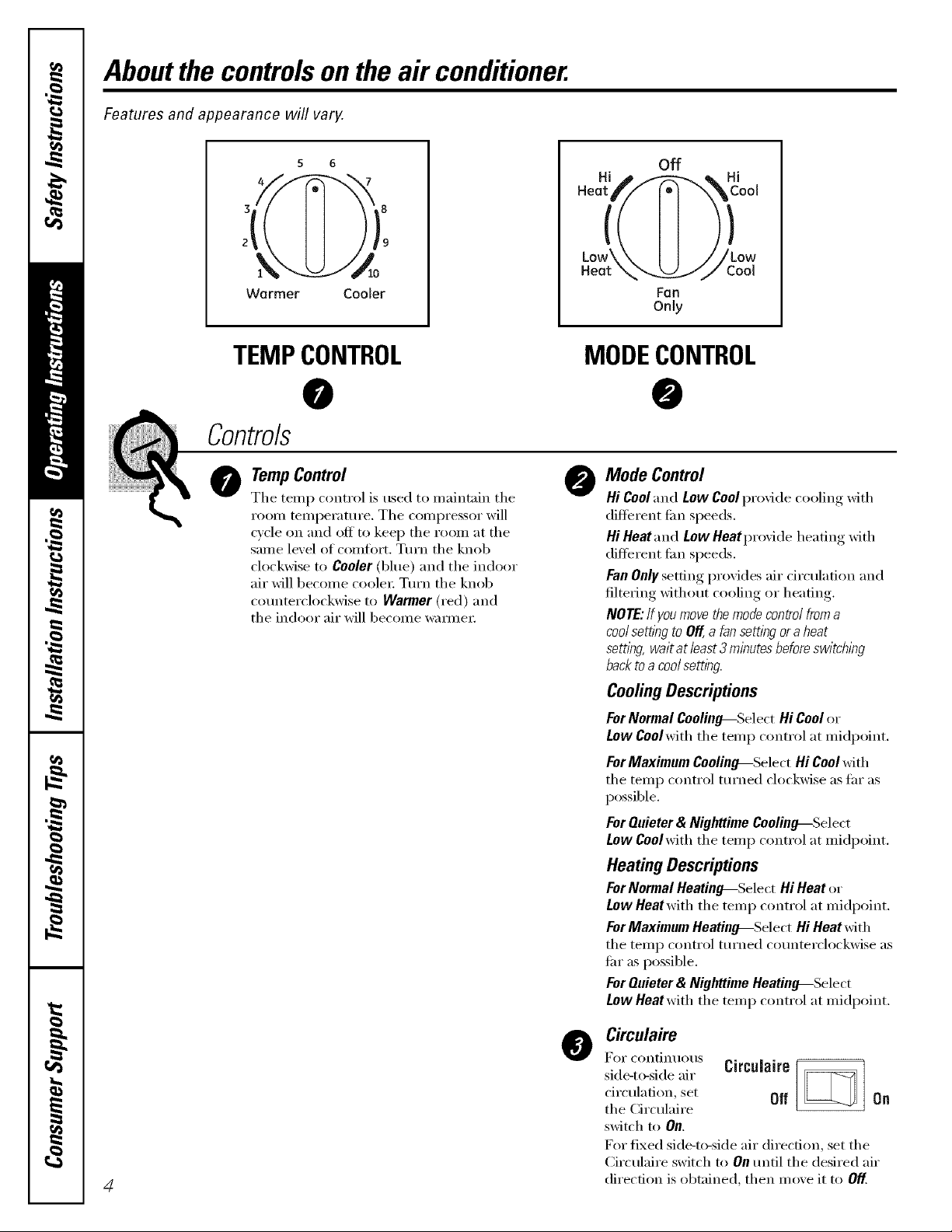
Aboutthe controlsontheair conditioner.
Features and appearance will vary.
5 6
3F ' 8
))9
,k /o
Warmer Cooler
TEMPCONTROL
0
Controls
TempControl
0
The temp control is used to maintain the
room temi)eramre. The compressor will
cycle on and off to kee I) the room at the
same level of comfort. Turn the knob
clockwise to Cooler (blue) and the indoor
air will become coole_: Turn the knob
counterclockwise to Warmer (red) and
the indoor air will become _m_ne_:
Hi _ _ _ Hi
off
[1?i°°'
Low\\ I I ///Low
Heat __J CoN
Fan
Only
MODECONTROL
@
Mode Control
@
Hi Cooland Low Cool provide cooling with
different tim speeds,
Hi Heat and Low Heat pr(>vide heating with
different tim speeds,
Fan Only setting provides air drculation and
filtering without cooling or heating.
NOTE:If youmove themode control froma
coolsetttbg to Off,,a fan setting or a heat
settlbg, wait at /east 3 minutes beforeswitching
back toa coolsetting.
CoolingDescriptions
For Normal Cooliuo--.Select Hi Cool or
Low Coolwith the temp control at midpoint.
For Maximum Cooling--Select Hi Cool with
the temp control turned clockwise as tar as
possible.
For Quieter & Nighttime Coolino--Select
Low Coolwith the temp control at midpoint.
Heating Descriptions
ForNormal Heating_Select Hi Heat or
Low Heatwith the temp control at midpoint.
ForMaximum Heatino---Select Hi Heat with
the temp control turned counterclockwise as
liar as possible.
For Quieter & Nighttime Heatino--Select
Low Heatwith the temp control at midpoint.
Circulaire
@
For continuous CircuJaire
side-to-side air
circulation, set Of[ Oil
the Circulaire
switch to On.
For fixed side-to-side air direction, set the
Circulaire switch to On tmtil the desired air
4
direction is obtained, then move it to Off.
Page 5
Additionalcontrols, gecom
Vent Control
The vent control is located al)ove the control
panels.
When set at CLOSE, only the air inside the roon_
will be circulated and conditioned. When set at
OPEN,some outside air is let into the room,
Toopen the vent, push the lever to the righL
Toclose it, push it to the left.
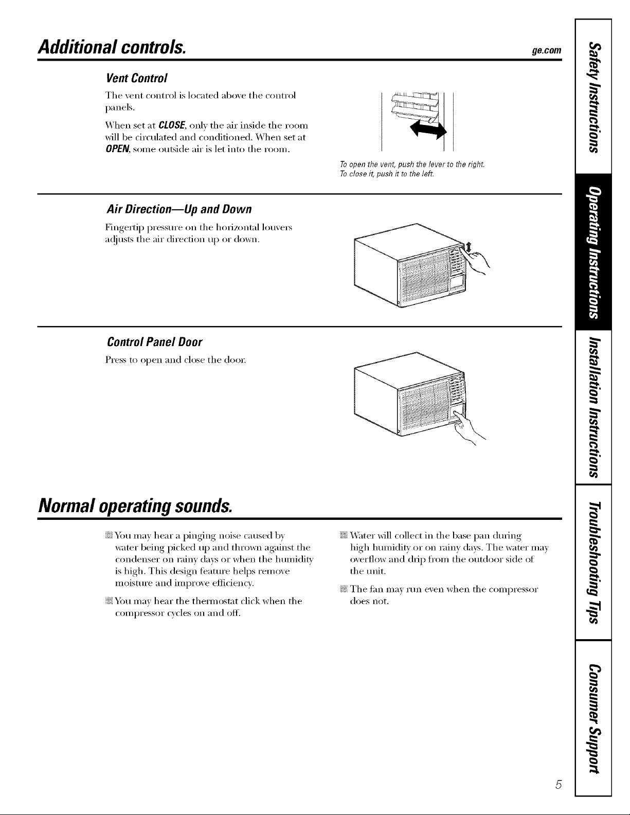
Air Direction--Up and Down
Fingertip pressm'e on tile horizont;fl lou\'e_
a(!justs the air direction up or down.
ControlPanel Door
Press to open and close tile d()()r
Normal operating sounds.
::Ji::Ybu may hear a pinging noise caused by
water being picked up and thrown against the
condenser on rainy days or when the humidity
is high. This design teature helps remove
moisture and improve eflicien W.
_: Y)u may hear the them_ostat click when tile
COIIII)I'eSSOI" cycles on _lIl(l olc[ '.
::Ji::Water will collect in tile base pan (hwing
high hmniditv or on rainv days. Tile water may
overflow and drip fl'om tile outdoor side ot
the mfit,
_: Tile ][ilIl Ill,IV I'[ln even when tile COllll)I'essor
does not.
Page 6

Careandcleaning of the air conditioner.
Grille and Case
Turn the air conditioner ott and remoxe the To clean, use water and a mild deter ,ent
l_lug, fron_ the wall outlet before cleaning, Do not use bleach or abrasix es.
OutdoorCoils
The ('oils on the outdoor side of the air conditioner
should be checked regularly. If they are clogged
with dirt or soot, fl_ev may be protessionally cleaned.
Air Filter
The air filter behind the fi'ont glille should be
checked and cleaned at least e\w y 30 days or
l//ore ()Den it Ilecessar_',
To remove:
] (-)pen the inlet grille upward by _ullin,, out the
bottom of the inlet grille.
] Using the tab, pull up slightl) on the filter
to release it and ptdl it down.
Clean the filter with wmm, soapy watel= Rinse and
let the filter dry bei_)re repladng it, Do not clean
the filter in a (iishwashel=
Grille Frame Removal fif necessary for coil cleaning)
Rein(we the air filteL See the Air Filter section above.
If present, remove the grille flmne am_chment screw.
Grasp the lower corne_ of the grille fl'ame while
pressing in on the case side tabs with your finger
tips. Pull out to release and lift it up.
NOTE'.Donotpull the bottom edge toward you more than Y'
or you may damagethe tabs of the grille.
A
CAOTlON:DoNoTopera,e,he
conditionerwithoutafilterbecausedirtandI/btwillclogit
and reduce performance,
_1',
Page 7

Installation
Instructions
Air Conditioner
I r_ Questions? Call 800.GE.CARES (800.432.2737) or Visit our Website at: ge.com
BEFORE YOU BEGIN
Read these instructions completely
and carefully.
• IMPORTANT - Savethese
instructions for local inspector's use.
• IMPORTANT - Observeall
governing codes and ordinances.
• Note to Installer - Be sure to leave these
instructions with the Consumer.
• Note to Consumer - Keep these
instructions for future reference.
• Skill level - Installation of this appliance
requires basic mechanical skills.
• Completion time - Approximately 1 hour
• We recommend that two people install
this product.
• Proper installation is the responsibility
of the installer.
CAUTION:
Do not, under any circumstances, cut or
remove the third (ground) prong from the
power cord.
Do not change the plug on the power cord
of this air conditioner.
Aluminum house wiring may present special
problems--consult a qualified electrician.
TOOLS YOU WILL NEED
Phillips head screwdriver
Adjustable wrench
I
Flat-blade screwdriver
• Product failure due to improper installation
is not covered under the Warranty.
• You MUST use all supplied parts and use
proper installation procedures as described
in these instructions when installing this
air conditioner.
(_) ELECTRICAL REQUIREMENTS
The 3-prong grounding plug minimizes the
possibility of electric shock hazard. If the wall
outlet you plan to use is only a 2-prong outlet,
it is your responsibility to have it replaced with
a properly grounded 3-prong wall outlet.
Some models require 230/208-volt a.c.,
©
protected with a time delay fuse or circuit
breaker. These models should be installed
on their own single branch circuit for
best performance and to prevent
overloading house or apartment wiring
circuits, which could cause a possible
fire hazard from overheating wires.
Pencil
Level
Power cord includes a current interrupter
device. A test and reset button is provided on
the plug case. The device should be tested on a
periodic basis by first pressing the TEST button
and then the RESET button. If the TEST button
does not trip or if the RESET button will not stay
engaged, discontinue use of the air conditioner
and contact a qualified service technician.
Ruler or tape measure
Scissors or knife
Page 8

Window Installation Instructions
PARTS INCLUDED
(Appearance may vary)
Window
sash seal
Left
accordion
panel
/
-5 Foam top /
mou_PingWin dow gask_
Right
accordion
panel
-- V-support (2)
Window locking
bracket (2)
Type A (6) Type B (4) Type C (6) Type D (6) Type E (4)
Bolt (2) & nuts (2)
8
Page 9

Window Installation instructions
[] WINDOW REQUIREMENTS
• These instructions are for a standard
double-hung window. You will need to
modify them for other types of windows.
• All supporting parts must be secured
to firm wood, masonry or metal.
• The electrical outlet must be within
reach of the power cord.
[ j
B===8
18" min.
30" to 41"
(With accordion panels)
STORM WINDOW REQUIREMENTS
[]
A storm window frame will not allow the
air conditioner to tilt toward the outside,
and will keep it from draining properly.
To adjust for this, attach a piece of wood
to the stool,
WOOD PIECES-
WIDTH: 2"
LENGTH: Long enough to fit inside the
window frame.
THICKNESS: To determine the thickness,
place a piece of wood on the stool to
make it 1/2" higher than the top of the
storm window frame or the vinyl frame.
Attach securely with nails or screws
provided by the installer.
[] REMOVE THE AIR CONDITIONER
FROM THE CASE
[] Remove the inlet grille.
[] Remove the filter.
I_q Remove the painted screws from each side
L_J
and the screw in the front. Save to reinstall
later.
"11 /
........ -
Screw ........_
[] Grasp the lower corners of the grille frame
while pressing in on the case side tabs with
your finger tips. Pull out to release and lift
it up,
NOTE: Do not pull the bottom edge toward
you more than 3" or you may damage the
tabs of the grille.
Screw
Screw
1/2" higher
than storm
window
fra me
Storm window
fra me
1/2" higher
than vinyl frame
(on some windows)
Stool
Vinyl frame
9
Page 10

Window Installation Instructions
[] REMOVE THE AIR CONDITIONER
FROM THE CASE (cont.)
I_q Remove the locking screw and locking
L_J
bracket from the lower frame. Save to
reinstall later.
I_q Remove the ground screw and save to
ii i
reinstall later,
_'_ Remove the ground screw
and save to reinstall later
[] Slide the air conditioner from the case by
gripping the base pan handle and pulling
forward while bracing the case.
[] PREPARE THE CASE
[] Install the top mounting rail with 4 type B
screws from the inside of the case.
Press firmly to drive the screws into the
gasket and through the top mounting rail.
Insert the frames for the accordion panels
[]
into the top mounting rail and the bottom
frame guides. Attach the accordion panels
to the side of the case using 3 type A screws
on each side.
NOTE: When attaching the accordion panels,
make sure to only screw the inner panels
to the case sides.
Top mounting rail
[] PREPARE THE WINDOW
Cut the window sash seal to the proper
length. Peel off the backing and attach the
seal to the underside of the window sash.
Type A
screws
BACK
Bottom mounting rail
Page 11

Window Installation instructions
INSTALL THE CASE
[]
IN THE WINDOW
Carefully slide the case into the window and
[]
center the case. Lower the window behind
the top mounting rail. Pull the bottom of the
case forward so that the bottom mounting
rail is tight against the back of the window
stool, Mount the case to the window sill using
4 type E screws. Drill pilot holes, if necessary.
Stool
Make sure the bolts
[]
and nuts are all of the
way in both the left
and right V-supports.
[] INSTALL THE CASE
IN THE WINDOW (cont.)
[] Extend the left and right accordion panels
to the vertical window sashes. Drill pilot
holes and attach the top and bottom
corners with 4 type D screws.
Top moun
Type D
screw
Type D
screw
Type D
screw
D
screw
[] INSTALL SUPPORT BRACKETS
AND THE FOAM TOP WINDOW
GASKET
[] Drill pilot holes and attach the support
brackets with two type D screws, one on
each side,
Position the V-supports
[]
on the case bottom so that .
they will be near the outside
wall. Attach a V-support to
each side of the bottom of
the case using type C
screws, 3 on each side.
Use a wood block (obtained
[]
locally) between the leveling
bolts and the wall if the wall
is weak or if the weight of the
air conditioner falls between
the studs in the wall.
Adjust the leveling I_
[]
bolts and nuts against
the outside wall so
that the case has a
slight tilt to the outside.
Tighten nuts with an
adjustable wrench. Use
a level; no more than a
1/2 bubble will be the correct case slant to the
outside.
IRq Cut the foam top window gasket to the
I,-,I
window width.
[] Stuff the foam between the glass and the
window to prevent air and insects from
getting into the room.
f I :4
11
Page 12

Window Installation Instructions
[] INSTALL THE AIR CONDITIONER
IN THE CASE
[] Make sure the ground
wire is off to the side
and slide the air j
conditioner into the
case. Do not push
on the controls or the
finned coils. Make
sure the air
conditioner is
firmly seated.
[] Reinstall the locking bracket and screw
removed earlier.
[] Reconnect the ground wire to the air
conditioner using the screw removed earlier.
IMPORTANT: The ground wire must be
reinstalled to ensure a proper ground.
[] INSTALL THE AIR CONDITIONER
IN THE CASE (cont.)
Press the grille frame in around the power
[]
cord on the right side. Secure the grille with
the painted screws on each side and the
screw in the front that were removed
earlier.
#/
Screw ........
Screw
\
Screw
[] Reinstall the filter.
[] Reattach the front grille frame to the case
by inserting the tabs on the grille frame into
the slots on the front top of the case.
Guide the lever carefully
through the grille frame
as you push it in.
[] Reinstall the inlet grille. Connect power.
Caulk or weather-strip any gaps or openings
to the outside to seal the installation.
12
Page 13

Through-the-Wall Installation InstructionsmOptional
The case may be installed through-the-wall
in both existing and new construction.
Read completely, then follow step-by-step.
NOTE: Except for the V-support
assemblies (included), obtain all materials
locally for mounting the air conditioner
through-the-wall.
[]
IMPORTANT
Through-the-wall installation is not
appropriate if any of the side or top louvers
in the case will be obstructed by the wall.
All side and top louvers in the case must
project on the outdoor side of the wall.
The room side of the case must project
into the room far enough to maximize the
balance of the unit.
The case must be installed level from side-
to-side and with a slight tilt from front to
rear. Use a level; no more than a 1/2 bubble
will be the correct case slant to the outside.
Lintel angle is required to support bricks or
blocks above opening.
Flashing is required and should extend the
length of the opening to ensure no inside
cavity leakage occurs.
Remove the air conditioner from the case.
[]
For specific instruction, refer to the Window
Installation Instructions.
Make certain that a wall receptacle is
[]
available close to the hole location or make
arrangements to install a receptacle.
[] IMPORTANT (cont.)
Secure with 14 wood screws anchored at
least an inch into the wall support structure.
NOTE: Drill pilot holes, if necessary, for
proper installation. If the frame is oversized,
use shims to prevent case distortion.
[] Install the V-supports. See the INSTALL
THE CASE IN THE WINDOW section in the
Window Installation Instructions.
[] FINISH THE WALL OPENING
[] Caulk all four sides on the outdoor side of
the case to prevent moisture from getting
through to the interior wall. Use of flashing
(drip rail) will further prevent water from
dripping inside the wall and down the
outside of the building.
Plaster line
Lintel angle
Caulking Trim molding
OUTSIDE !-
Air louvers
(top and l
sides must
project on the
outdoor side
of the wall)
Wood filler and
caulking (above
and below the
flashing)
V-supl
Flashing
(Drip rail)
Bottom
rail
(if desired)
INSIDE
Bottom rail
J
[] Place the case in the wall opening and
place wood support strips between the case
bottom and the flashing on both sides of the
bottom rail. They should be the same height
as the bottom rail and the same length as
the wall opening.
Flashing
(Drip rail)
FR] Place the air conditioner into the case.
For specific instruction, refer to the Window
Installation Instructions.
Wood support strips
13
Page 14

Beforeyoucall forservice... Review the chart below first and you may not need to call for service.
Possible Causes
Air conditioner The air conditioner • Make sure tile air condititmer plug is pushed completely
does not start is unplugged inu) th e outlet.
The fuse is blro_a/circuit • Check tire house fi/se/circuit breaker box and replace
breaker is tripped tire fl/se or reset tire breaker:
Power failure
The current interrupter • Press tire RESk'Tbutton h>cated on tire power cord plug.
device is tripped • If tire RESETbutton will not stay elsga<red discontimw
Air conditioner Ice blocks the air flow • Set tire roo(le control at Fan Onlyor Hi Coolwith tire
What ToDo
• Tile refit will autoroaficallv re-start in tile settings last
used after tile power is restored.
• There is a protective time delay (approximately
3 minutes) to prevent tripping of tile compressor
overload. For this reason, tile unit mav not start
normal cooling or heating fin" 3 minutes after it
is turned back on.
use of tire air conditioner and contact a qualified selMce
technician.
freezing up and stops the air conditioner terop control at a wmmer setting.
from cooling the room
Air conditioner does not Airflow is restricted • Make sure there are no ('urtnins, blinds or flu'nitm'e
cool as it should bh>cking the fl'(>nt of the air ctmclitione_;
The terop control roay • Tm'n tire teroperature knob clockwise as flu" as possible.
not be set correctly
The air Filter is dirty • Clean tire filter :It least every 30 days. See tile Operating
Instructionssection.
The roooro roay have been hot • _4]wn tire air conditioner is titst turned on you ]seed
to allow tilne tOl" tire 1"00111 to CO01 dowls.
Cold air is escaping • Check fi)r ellen rims:Ice floor registers and
Cooling coils have iced up • See "Air conditioner freezing up" above.
Air conditioner does not Airflow is restricted • Make sure there are no curtains, blinds or flu'nitm'e
warm as it should bh)cking the fl'()nt of the air c(mclitione_;
The terop control roay • Tm'n tire knob cotmterclockwise :is flu" :is possible.
slot be set low enough Tire lowest setting provides maxim um wmroing.
The air Filter is dirty • Clean tire filter :It least every 30 days. Sue tile Operating
c()ld air returns.
• Set the air conditioner's vent to the ch)sed position.
Instructions secti(m.
The rooro may have been cold • When tire air conditioner is titst turned on, you need to
:lllow [ils/e toy the I'OOlll to w_lI]ll I/l),
Warm air is escaping • Check fi)r ellen flu'hate floor registe_ and
cold air returns.
Waterdripsoutside Excessively hot mid • This is hernial.
hronid weather
Waterdrips indoors The air conditioner is not • For proper water disposal, make sure tire air conditioner
tilted to the outside slants slightly fl'oro tire case fl'ont t(> tire rein:
Watercollectsin
basepan
14
Moisture is removed froro
indoor air and dxaJns into
rear of a cabinet where a fan
blows it against the outdoor
condenser coil
• This is n(mnal fl)r a short period in areas Mth
little hmnidiF; nomml for a longer period in very
humid areas.
Page 15

GEAir ConditionerWarranty.
All warranty service provided by our Factory Service Centers,
or an authorized Customer Care®technician. Toschedule service,
on-line, 24 hours a day, vis# us at ge.com, or call 800.GE.CARES
(800.432.2737).Have serial number and model number available
Staple your receipt here.
Proof of the original purchase
date is needed to obtain service
under the warranty.
when calling for service.
GE Will Replace:
Any pattof the air conditioner which tifils due to a detect in materials or workmanship.
Fromthedateof the During this limited one-year warranty,(;E will also provide, free of charge,all labor and related
originalpurchase service to replace the cleie('fixe part,
_ Service trips to your home to teach you how to
use the product.
::Ji_:Improper installation, delivery or maJntenmzce. If you
have an h_staJlation problem, or if the air conditioner
is of improper cooling capacity for the intended use,
contact your dealer or hlstaJler. You axe responsible
for providing adequate electrical comzecthlg facilities.
::Ji::Failure of the product resulting from modifications to
the product or due to tumeasonable use including failure
to provide reasonable m_d necessmy ma'_mtenmlce.
_: In commercial locations, labor necessary to move the
unit to a location where it is accessible for service
by an individual tecl_ficiml.
!i_:Replacement of house fuses or resetting of circuit
breakers.
::Ji::Failure due to corrosion on models not corrosion-
protected.
_: Dmnage to the product caused by hnproper power supply
voltage, accident, f'tre, floods or acts of God.
_: h_cidentaJ or cousequentiaJ dmnage caused by possible
defects with this air conditioner.
iJi::Dmnage caused after delivery.
Limited Warranty, Any implied warranties, including the implied warranties of merchantability or fitness for a
I EXCLUSION OFIMPLIED WARRANTIES--Your sole and exclusive remedy is product repa# as provided in this
particular purpose, are limited to one year or the shortest period allowed by law.
This warranty is extended to the original purchaser and any succeeding owner for products purchased for home
use within the USA. In Alaska, the warranty excludes the cost of shipping or service cats to your home.
Some states do not allow the exclusion or limitation of incidental or consequential damages. This warranty gives
you specific legal rights, and you may also have other rights which vary from state to state. Toknow what your
legal rights are, consult your local or state consumer affairs office or your state's Attorney General.
Warranter: General Electric Company, Louisville, KY 40225
/5
Page 16

ConsumerSupport.
Hme a question o_ need assistance _ith }our appliance? Tr} the (;E Appliances "_ ebsite 24 hotu_ a day,
q l GEAppliancesWebsite ge.com
' an} da} of the }ear! For greater comenience and ihster serxice, }ou can no_ downlo _cl Owne_ 's Manu fls,
order parts or exert schedule service on-line.
ScheduleService
Expert GE repair service is onl} one step awa_ _i'om _our dooc Get on-line and schedule _our service at
}our convenience 24 hours an? da? of the ?ear! Or call 800.GE.(_AI_ES (800A32.2737) during n(mnal
business hours.
ge.corn
RealLifeDesignStudio go.corn
(;E supp(n_s the l_)nive_al Design concept--products, services and environments that can be used by
people ot aLl ages, sizes and capabilities. We recognize the need to design tbr a wide range of physical and
mental abilities and impaim_ents. For details of GE's Universal Design applications, including kitchen
design ideas fiw people with disabilities, check out our Website toda> For the hearing impaired, please call
800.TDD.GEAC (800.833A322).
ExtendedWarranties
Purchase a GE extended warrant} and lean* about special discounts that are axailable while }our warrant}
is still in effect. You can pro'chase it on-line amtime, or call 8 .626.2224 during normal business hours.
GE Consumer Home Services will still be there after }our warrant} expires.
PartsandAccessories
go.corn
ge.corn
Individuals qualified to sel-dce their own appliances can have pm_s or accessories sent directly to their
homes (VISA, MasterCard and Disco\ er cards are accepted). Order on-line toda), 24 houl_ evel)' clay
or by phone at 800.626.2002 during n(mnal business hours.
Instructions contained in this manual cover procedures to be pedonned by any user. Other servicing generally
should he referred to qualified service personnel. Caution must be exercised, since improper servicing may cause
unsafe operation.
ContactUs
If you are not satisfied with the service you receive fi'om GE, contact us on our Website with all the details
including your phone numbel; or write to: General Managel; Customer Relations
GE Appliances, Appliance Park
I_ouisville, KY 40225
Register your new appliance on-line---at your convenience! Timel} prodtlct registration xdll allow flw
enhanced communication and prompt serxice under the temps of }our _arranty, should the need arise.
l RegisterYourAppliance
YOu ma} also mail in the pre-p_Jnted registration card included in the l)acldng, material.
go.corn
go.corn
Printed in China
 Loading...