

Page 1
g
ESL 429/449 Series
Self-Diagnostic Photoelectric
Smoke Detectors
Installation Instructions
Description
The ESL 429/449 Series low-profile, self-diagnostic, two-wire and
four-wire smoke detectors work on the light scattering principle. A
pulsed infrared light-emitting diode serves as the light source, and a
high-speed photo-diode as the sensing element. This design has
superior protection against false alarms caused by dust, insects,
RF , and ambient light.
These smoke detectors are especially suited for residential
occupancies, including hotels, motels, and dormitories, as well as
other commercial and industrial fire-system applications. This
series is designed for two-wire and four-wire connection to 6-24
VDC fire alarm control panels, UL Listed for commercial or
household fire protection.
Features
Self-diagnostics including automatic sensitivity testing. Each
detector in the series continually monitors its own sensitivity and
operational status (see Maintenance).
A wide range of optional features are offered as shown in the
Product Selection Guide. To provide for almost any application,
these options include a built-in sounder, an auxiliary relay , an
integral heat detector, and an isolated heat detector .
California State Fire Marshal Approved
MEA (New York City) Approved
Where to Locate the Required Smoke Alarms in New Construction.
All of the smoke alarms specified for existing construction are
required and, in addition, a smoke alarm is required in each
bedroom.
A.
B.
Dining
Room
TV Room
Kitchen
Living Room
Dining
Room
Bedroom
Kitchen Bedroom
FM
APPROVED
Bedroom
Bedroom
Selecting a Location
Selecting a suitable location is critical to the operation of smoke
alarms. This equipment should be installed in accordance with the
National Fire Protection Association’s (NFPA) Standard 72. See
Figure 1.
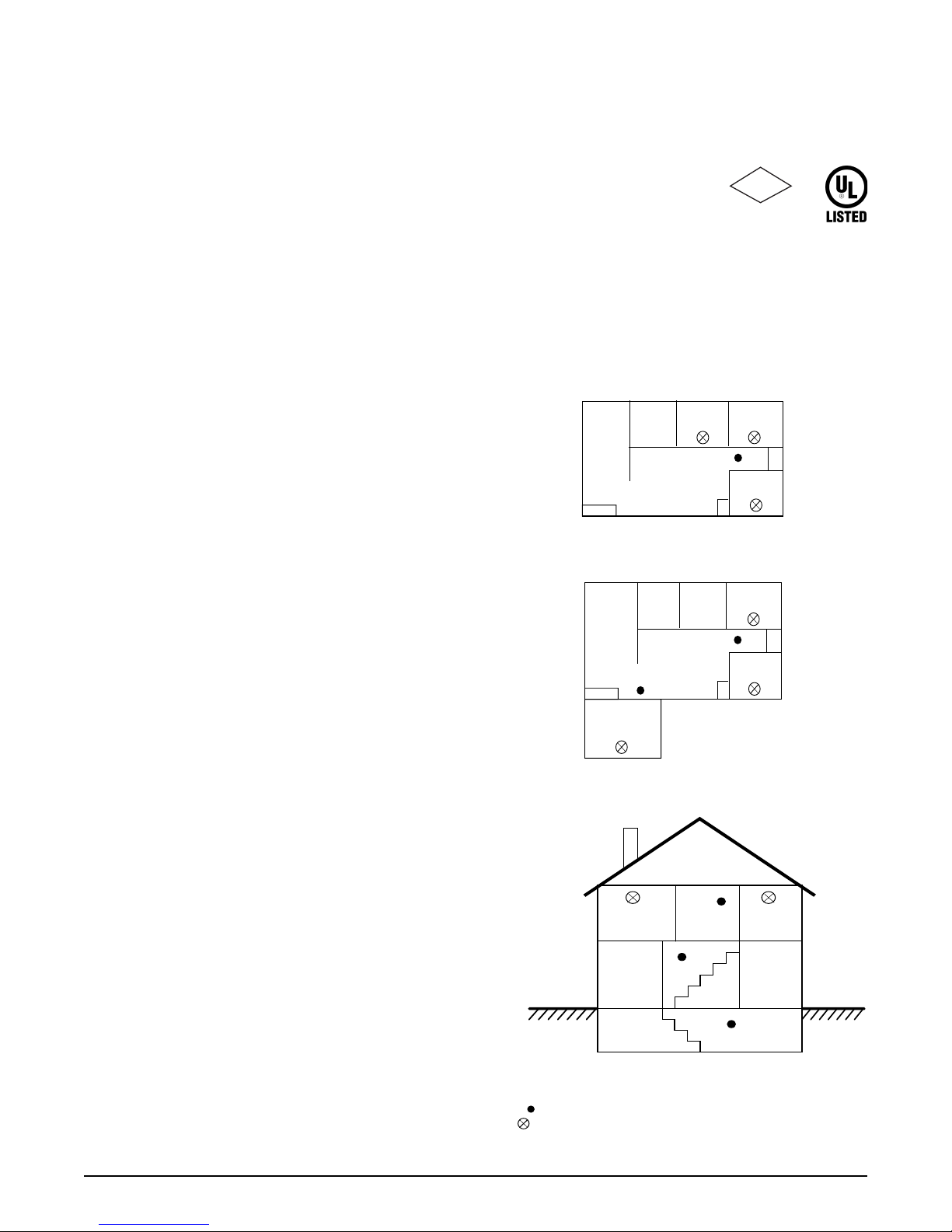
A-11-8.3.a Where to Locate the Required Smoke Alarms in
Existing Construction.
The major threat from fire in a family living unit occurs at night
when everyone is asleep. The principal threat to persons in
sleeping areas comes from fires in the remainder of the unit.
Therefore, a smoke alarm(s) is best located between the bedroom
areas and the rest of the unit. In units with only one bedroom area
on one floor, the smoke alarm(s) should be located as shown in
Figure 1 A.
In family living units with more than one bedroom area or with
more than one floor, more than one smoke alarm is required, as
shown in Figure 1 B.
In addition to smoke alarms outside of the sleeping areas, the
installation of a smoke alarm on each additional story of the family
living unit, including the basement, is required. These installations
are shown in Figure 1 C. The living area smoke alarm should be
installed in the living room or near the stairway to the upper level,
or in both locations. The basement smoke alarm should be installed
in close proximity to the stairway leading to the floor above. Where
installed on an open-joisted ceiling, the alarm should be placed on
the bottom of the joists. The alarm should be positioned relative to
the stairway to intercept smoke coming from a fire in the basement
before the smoke enters the stairway.
Living Room
Bedroom
C.
Bedroom
Living
Room
Basement
= Required smoke alarms
= Additional smoke alarms required for new construction
Figure 1 . Detector Location
Bedroom
Bedroom
Dining
Room
ESL 429/449
1
Page 2
ceiling
4”
(10cm)
acceptable here
Note
Measurements shown are to the
closest edge of the detector.
Figure 2. Detector Placement
never here
top of detector
acceptable here
4”
(10cm)
side wall
12”
(30cm)
maximum
Are More Smoke Alarms Desirable?
The required number of smoke alarms might not provide reliable
early warning protection for those areas separated by a door
from the areas protected by the required smoke alarms. For this
reason, it is recommended that the householder consider the use
of additional smoke alarms for those areas for increased
protection. The additional areas include the basement, bedrooms, dining room, furnace room, utility room, and hallways
not protected by the required smoke alarms. The installation of
smoke alarms in kitchens, attics (finished or unfinished), or
garages is not normally recommended, as these locations
occasionally experience conditions that can result in improper
operation.
Important !
Regulations pertaining to smoke detector
installations vary from state to state. For more
information, contact your local fire department
or local authority having jurisdiction.
In addition to NFPA 72, use the following location guidelines to
optimize performance and reduce the chance of false alarms:
• Locate ceiling-mounted smoke detectors in the center of a
room or hallway at least 4 inches (10cm) from any walls or
partitions.
• Locate wall-mounted smoke detectors so the top of the alarm
is 4 to 12 inches (10 to 30cm) below the ceiling. See Figure 2.
• When more than one detector is required, spacing of 30 feet
(9m) may be used as a guide on smooth ceilings. Other
spacing may be used depending on ceiling height, high air
movement, and other conditions or response requirements.
• Locate in a suitable environment as follows:
- Temperature between 32°F (0°C) and 100°F (38°C)
- Humidity between 0 and 95% non-condensing
• Locate away from air conditioners, heating registers and any
other ventilation source that may interfere with smoke
entering the detector.
• Locate away from kitchens, wood stoves, garages, furnaces,
and bathrooms.
• Mount smoke detectors on a firm permanent surface,
typically a stud or metal runner.
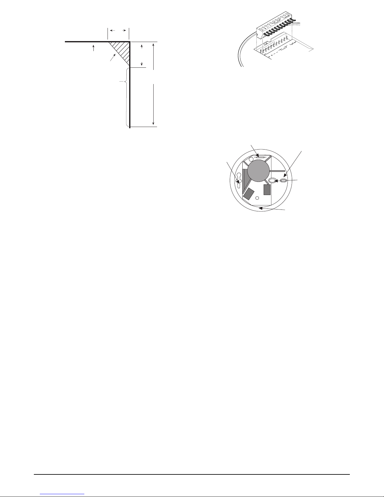
Figure 3. Plug-in Terminal Block
Note
For instructions on removal of terminal block and
circuit board, call technical services at 800-648-7424.
4” square or
WIREMOLD mounting
(No. 5739)
single gang
4” octagon
mounting
cover release
mounting
all boxes
test switch
Figure 4. Detector Mounting
Installation
The detectors mount to standard single-gang electrical boxes,
four-inch octagonal or four-inch square electrical boxes, or on
WIREMOLD No. 5739 fixture boxes. The detectors may also be
mounted directly to walls or ceilings where local codes/
jurisdictions permit.
1. Pull wire through the electrical box and connect to the plug-in
terminal block supplied, one wire per terminal. See Figures 3
and 5.
2. Dress wiring neatly and snap the terminal block into the back
of the detector.
Note
The detector cover must be closed completely, to support the circuit board, while installing the terminal
block.
3. Open the cover and mount the detector, using the mounting
holes provided. See Figure 4.
Note
Positive air pressure from wire openings, conduit,
mounting boxes, irregular mounting surfaces, or
plenums causing air movement through and away from
the detector may prevent proper operation. Seal all
openings causing unwanted air flow using UL Listed
expanding foam or Duxseal.
4. Remove the red plastic dust cover from the detector. The
detectors are shipped with a dust cover for protection on
construction sites with dusty environments.
2
ESL 429/449
Page 3

429 Series Wiring Diagram
Models 429AT , 429C,
Compatible Listed
Control Unit*
fire alarm
initiating
circuit
+
–
first detector
449 Series Wiring Diagram
first detector
Models 449
AT, C, CT, CST
alarm
contact
429CT, 429CST
power
power
++--
Model 429CRT
auxiliary
contacts
++--
powernot used
last detector
++--
* Two-Wire Compatibility
Refer to ESL’s Compatibility
Index for compatible control
panel listings.
End-of-Line
Device
auxiliary
contacts
Models 449
CRT, CSRT
alarm
contacts
power
local non-
smoke alarm
++--
latching
contacts
Models 449
CSRH*
heat sensor
contacts
power
--
last detector
++
* The 449CSRH units
are smoke alarms with
isolated heat detectors.
Listed Control Unit
DC
+
power
–
circuit
fire alarm
initiating
circuit
Figure 5. Wiring Diagrams
Supervision of System Wiring
Power wiring in four-wire systems is required by NFPA 72 to be
supervised. This is accomplished by installing a power supervision relay at the end of the detector power circuit. The contacts of
the supervision relay are wired in series with the system’s alarm
initiating circuit, and are closed when energized (see Figure 5). A
break in the detector power circuit or a loss of power de-energizes
the power supervision relay, opening the contacts and causing a
trouble annunciation at the fire alarm control unit.
ESL models 204-6 V and 204-12/24 V are relays UL Listed for
four-wire power supervision. Models 449CTE and 449CSTE are
smoke detectors with a built-in end-of-line power supervison
relay , and can be used to supervise a circuit in place of a power
supervison relay. The 449CTE and 449CSTE will also automatically send a trouble signal to the control panel whenever the
detector needs maintenance.
red
black
brown
Power
Supervision
Unit
brown
End-of-Line
Device
Smoke Test
The units should be tested in place annually using one of the
following methods:
A. Use Smoke! in a can® and follow the directions on the can.
B. Hold a smoldering punk or cotton wick close to the unit
and gently direct the smoke into the smoke entry openings
for 20 seconds or until an alarm is indicated.
Be sure to properly extinguish the smoke source after
testing! This is a go/no go test and is not a reliable indication of
detector sensitivity. If it is successful, the LED will remain lit.
To reset the detector, operate the system reset switch to remove
power from the detectors. The control unit alarm and all
auxiliary functions should be verified for a complete test of each
detector.
Installation Test
After all connections are complete and the wiring is checked for
errors, apply power to the system. There should be no alarm. If
an alarm is reported, determine if a detector is latched in alarm or
if there is a problem with the wiring.
ESL 429/449
Heat Test
Models with heat sensors sample for heat every 3 seconds. Test
heat sensors by using a hot air gun. Aim the gun at the heat
sensor from 6-10 inches (15-25cm) away. The detector should go
into alarm in less than 30 seconds.
3
Page 4

Sensitivity Test
1. Hold the magnet on the hinge side of the unit for more than
one second (see Figure 7). The LED will flash 1 to 9 times.
2. Count the number of LED flashes, then use the following
table to determine if any action is necessary.
Flashes
0-1 Indication: Unservicable hardware fault.
Action: Reset and rerun sensitivity test. If the
error persists, replace unit.
2-3 Indication: Unit is becoming insensitive.
Action: Clean and reset the unit. Rerun
sensitivity test. If the error persists,
replace the unit.
4-7 Indication: Unit is within normal sensitivity range.
Action: N/A
8-9 Indication: Unit is becoming too sensitive.
Action: Verify the optical chamber is snapped
down securely. Clean the unit and
replace the optical chamber.
After the sequence of flashes, if the sensitivity is within limits
and all other tests pass, the unit goes into alarm until reset by
the panel. If the sensitivity is not within limits, or an unserviceable hardware fault is detected, the alarm LED will continue to
flash once per second until the unit is reset by the panel.
optical block chamber
indentation
snap into indentation
Figure 6. Detector Maintenance
SQUEEZE
LED
HERE
optical base
Note
CSRH models auto reset.
Maintenance
The smoke detectors are designed for easy field service and
maintenance. If a detector drifts beyond its approved sensitivity
range for more than 24 hours, or fails internal diagnostic tests, the
unit automatically indicates trouble by flashing its LED every
second. This meets field sensitivity testing requirements without
the need for external meters.
Note
Connect to a power supply that will not automatically
reset. Since the self-diagnostics only indicate trouble
after 27 hours, if the power supply automatically resets
every 24 hours the self-diagnostic indication will never
be signaled (the smoke detector will still signal alarm
correctly).
In accordance with NFPA 72, smoke detector sensitivity should
be checked within one year after installation and every alternate
year thereafter, in commercial installations, or every three years in
residential sites. See Sensitivity T est.
The detector’s replaceable optical block chamber unsnaps for easy
field cleaning and service. Whenever the status LED indicates
cleaning is necessary, follow these steps:
1. Open the detector cover, unsnap and throw away the optical
block chamber. See Figure 6.
2. Thoroughly blow off the optical base and snap a new optical
block chamber (part #211) back in place.
Note
Be sure the new optical block chamber is seated all the
way down.
3. Close the detector cover and verify sensitivity. See Sensitivity
Test.
magnet
Figure 7. Sensitivity Testing
Approvals
The smoke detectors are for use in commercial fire protective
signaling systems and in household fire warning systems
(NFPA 72).
429/449 Series
Listed by Underwriter’s Laboratories; California State Fire
Marshal approved (Listed # 7272-0447-128); MEA approved
(New York City) (Listed # MEA 64-94-E) Factory Mutual
approved.
4
ESL 429/449
Page 5

Planning for Emergencies
Develop a plan to prepare for emergency situations. Discuss and
rehearse your plan with everyone by doing a fire drill every few
months.
WARNING
Do not enter a building where sirens are sounding
Guidelines
• Understand how to use your fire system.
• Know the normal state of doors and windows: open, closed, or
locked.
• Escape fast! (Do not stop to pack.)
• Use a different escape route if closed doors feel hot to the
touch.
• Crawl and hold your breath as much as possible to help reduce
smoke inhalation during your escape.
• Meet at a designated outdoor location.
• Emphasize that no one should return to the premises if there is
a fire.
• Notify the fire department from a phone in another building.
Your Floor Plan
When establishing your escape routes, consider the following
guidelines:
• Have a drawing for each building level.
• Show all exits (two exits per room are recommended).
• Show the location of stairwells and fire escapes.
• Show the location of all components of the fire system.
• Show the locations of all fire extinguishers, hoses, ladders, etc.
WARNING
Smoke detectors CANNOT provide warnings for
fires resulting from explosions, smoking in bed or
other furniture, ignition of flammable liquids,
vapors and gases, children playing with matches or
lighters.
Warning! Limitations of Smoke
Detectors
Smoke detectors are very reliable, but may not work under all
conditions. No smoke detector provides total protection of life or
property. Smoke detectors are not a substitute for life insurance.
Unreliable transmission or receiving of radio frequency
(RF) signals may occur if the system is not installed,
located, serviced and repaired properly. RF signals sent by this
detector may be blocked or reflected by metal objects. Adjacent
devices or systems using radio frequency signals may interfere with
the operation of this alarm. Test the system often to be sure that
signals are being sent and received properly.
Smoke detectors may not be heard. A sound sleeper or
someone who has taken drugs or alcohol may not awaken if the
detector is installed outside a bedroom. Closed or partially closed
doors and distance can block sound. This detector is not designed
for the hearing impaired.
Smoke detectors may not always activate and provide
warning early enough. Smoke detectors only activate when
enough smoke reaches the detector. If a fire starts in a chimney,
wall, roof, on the other side of closed doors, or on a different level
of the property enough smoke may not reach the detector for it to
alarm.
Limited Warranty
ESL is a brand of GE Security. The manufacturer warrants this
smoke detector to be free from defects in material and workmanship under conditions of normal use for a term of 3 years from the
date of manufacture.
During the warranty period, if a GE Security product or any of its
components becomes defective, it will be repaired or replaced
without charge.
Out-of-warranty units will be repaired at the discretion of the
manufacturer or, if not, a card will be forwarded to the customer
suggesting a replacement unit and the cost of that unit.
This warranty does not apply to units which have been subject to
abuse, misuse, negligence or accident, or to which any modifications, alterations or repairs have been made or attempted.
This warranty is extended only to the original purchaser of the
smoke detector and may be enforced only by such person. During
the warranty period, if the detector or any warranted components
thereof becomes defective, it will be replaced or repaired without
charge at the manufacturer’s discretion if returned in accordance
with the following instructions:
Obtain a Return Authorization Number by calling 1-800-648-7422
or 503-692-4052, then carefully pack the detector in a well padded
and insulated carton and return, postal charges prepaid to:
Customer Service RMA#
GE Security
12345 SW Leveton Drive
Tualatin, OR 97062-9938
A note should be included advising the nature of the malfunction.
Care must be exercised in the proper packing of detectors returned
under this warranty as GE Security will not be responsible for
warranty repairs to equipment damaged because of improper
packing.
The above warranty is in lieu of all other express warranties, and implied warranties of merchantability and fitness
for a particular purpose are limited in duration for a period
of THREE years from the date of manufacture. Under no
circumstances shall manufacturer be liable to the purchaser or any other person for incidental or consequential
damages of any nature, including without limitation
damages for personal injury or damages to property, and
however occasioned, whether alleged as resulting from
breach of warranty by manufacturer, the negligence of
manufacturer or otherwise. Manufacturer’s liability will
in no event exceed the purchase price of the product. Some
states do not allow limitations on how long an implied
warranty lasts, or the exclusion or limitation of incidental
or consequential damages, so the above limitations and
exclusions may not apply to you. Unless a longer period is
required by applicable law, any action against manufacturer in connection with this smoke detector must be
commenced within one year after the cause of action has
occurred.
No agent, employee or representative of the Manufacturer nor any
other person is authorized to modify this warranty in any respect.
Repair or replacement as stated above is the exclusive remedy of
the purchase hereunder. This warranty gives you specific legal
rights and you also have other rights which vary from state to
state.
Smoke detectors are a significant help in reducing loss,
injury and even death. However, no matter how good a
detection device is, nothing works perfectly under every
circumstance and we must warn you that you cannot expect
a smoke detector to ensure that you will never suffer any
damage or injury.
ESL 429/449
5
Page 6

Product Selection Guide
Series
Designator
449CSRT
Wire Type
Features
Designator Feature Description
E End-of-Line Power Built-in end-of-line relay that also acts as a sensitivity status output. For four-wire only. Fail-safe
H Isolated Fixed Temp. Isolated fixed 135°F (57°C) and rate-of-rise heat detector, independently trips the LED and alarm
R Auxiliary Relay Used to activate other devices such as elevator recall, door holders, etc. UL Listed for releasing services.
S Built-in Sounder 85db built-in sounder alarms when smoke is detected or when power wiring polarity is reversed.
T Integrated Fixed Temp. Integrated fixed 135°F (57°C) temp. and rate-of-rise heat detector offers double protection.
Supervisory and relay trips upon loss of power or if smoke detector is outside the approved sensitivity range for
Sensitivity Status more than one day. End-of-line resistor is easily connected to terminal with no extra wiring, or
Relay relay contacts can be connected to a separate trouble loop.
and Rate-of-Rise relay output. Smoke detector activates internal sounder (local alarm) and auxiliary relay, but does
Heat Detector not latch. Approved as both single station smoke alarm and system heat detector.
and Rate-of-Rise Either heat detector or smoke detector can trip and latch LED and alarm relay outputs.
Heat Detector
Model Designator
Features
Power Designator
Wire Type Model Designator Power Designator
Number Description Designator Listing Designator Power
2 Two-wire only 9 UL A 6/12 VDC
4 Four-wire only C 12/24 VDC
Electrical Specifications
Model 2-Wire 4-Wire Min.Volt. Max.Volt. Max. Ripple Typ.Avg.Stby. Typ. Alarm Cur. Typ.Avg. Pol. Alarm Relay Other Relay
(PK to PK) Cur. (12-24V) (12-24V) Rev.Cur. Contacts Contacts
(V) (uA) (mA) (mA) (A) (A)
429AT * 6.5 20 10% 70 *see S09A - - 429C * 8.5 33 10% 70 *see S10A - - 429CT * 8.5 33 10% 70 *see S10A - - 429CRT * 8.5 33 10% 70 *see S11A - - 2
429CST * 8.5 33 10% 70 *see S11A 10 - 449C * 8.5 33 10% 70 15 - 0.5 449CT * 8.5 33 10% 70 15 - 0.5 449CRT * 8.5 33 10% 70 31 - 0.5 449AT * 5.1 27 10% 70 15 - 0.5 449CST * 8.5 33 10% 70 40 10 0.5 449CSRT * 8.5 33 10% 70 51 10 0.5 2
449CSRH ** * 8.5 33 10% 70 51 10 0.5 2
449CSTE * 8.5 33 10% 23mA 51 33 0.5 2
449CTE * 8.5 33 10% 23mA 31 23 0.5 2
Power Supervision Units
Model Min.V olt. Max. Volt. Typ. Avg. Stby.Cur.(uA) Relay Contacts (A)
204-6V (UL Listed) 5.1 15 33mA @ 6VDC 0.5
204-12/24V (UL Listed) 8.5 33 14mA @ 12VDC, 28mA @ 24VDC 0.5
Accessories
SM-200 Smoke! in a can® canned smoke for functional testing of smoke detectors
SM-EXT1 Smoke! in a can® extension accessory
211 Replacement optical blocks (set of 10)
241 Terminal block for 4-wire smoke detectors 449CTE, 449CSTE, 449AT, 449C, 449CT,449CST
* 429 models draw up to a maximum of 60mA current if not limited by panel.
** 449CSRH model is a smoke alarm with isolated heat detector.
Certain items in the installation instructions are protected under one or more of the following patents: 5,546,074; 5,798,701; 5,821,666;
6,756,906
Specifications
Operating temperature................... ...32°F to 100°F (0°C to 38°C)
Operating humidity range ....................... 0 to 95% non-condensing
Sounder specifications............................................ 85dB at 10 feet
Field wiring size............................................................ 14-24 A WG
Self-diagnostic indication .................. typically 27 hours after reset
(do not connect power supply that resets every 24 hours)
12345 SW Leveton Drive
GE Security
Tualatin, OR 97062
503-692-4052
Heat detector .................. fixed temp 135°F, 50 foot (15m) spacing
rate-of-rise 15°F/min > 105°F (8°C/min > 41°C)
Auxiliary relay contacts........ 2A @ 28VDC or 120VAC (resistive)
Alarm contacts .................................. 500mA @ 36VDC (resistive)
Dimensions ................. 6.1” (15.5cm) diameter x 1.9” (4.7cm) deep
Weight .....................................................................8.8 oz. (0.25kg)
Color ....................................................................................... white
USA & Canada: 800-547-2556
Tech Support: 800-648-7424
www.ge-security.com
14153D / September 2004
 Loading...