


369 Motor Management Relay
Digital Energy
Instruction Manual
369 Revision: 3.5x
Manual P/N: 1601-0077-BV
GE Publication Number: GEK-106288S
Copyright © 2011 GE Digital Energy
GE Digital Energy
215 Anderson Avenue, Markham, Ontario, Canada L6E 1B3
Tel: (905) 294-6222, 1-800-547-8629 (North America)
Fax: (905) 201-2098
Internet: http://www.gedigitalenergy.com
*1601-0077-BV*
GE Multilin's Quality Management
System is registered to
ISO9001:2000
QMI # 005094
UL # A3775

© 2010 GE Digital Energy Incorporated. All rights reserved.
GE Digital Energy 369 Motor Management Relay instruction manual for revision
3.5x.
369 Motor Management Relay, is a registered trademark of GE Digital Energy
Inc.
The contents of this manual are the property of GE Digital Energy Inc. This
documentation is furnished on license and may not be reproduced in whole or
in part without the permission of GE Digital Energy. The content of this manual is
for informational use only and is subject to change without notice.
Part numbers contained in this manual are subject to change without notice,
and should therefore be verified by GE Digital Energy before ordering.
Part number: 1601-0077-BV (November 2011)

TABLE OF CONTENTS
Table of Contents
1: INTRODUCTION ORDERING ........................................................................................................................................... 1-1
G
ENERAL OVERVIEW ........................................................................................................... 1-1
O
RDERING ............................................................................................................................ 1-2
A
CCESSORIES ....................................................................................................................... 1-3
F
IRMWARE HISTORY ............................................................................................................ 1-3
PC P
ROGRAM (SOFTWARE) HISTORY ............................................................................... 1-4
369 R
ELAY FUNCTIONAL SUMMARY ................................................................................ 1-5
R
ELAY LABEL DEFINITION ...................................................................................................1-8
2: PRODUCT DESCRIPTION OVERVIEW ........................................................................................................................................... 2-9
UIDEFORM SPECIFICATIONS ............................................................................................ 2-9
G
M
ETERED QUANTITIES ........................................................................................................ 2-10
P
ROTECTION FEATURES ...................................................................................................... 2-10
A
DDITIONAL FEATURES .......................................................................................................2-12
SPECIFICATIONS ............................................................................................................................... 2-13
I
NPUTS .................................................................................................................................. 2-13
O
UTPUTS ...............................................................................................................................2-15
M
ETERING ............................................................................................................................. 2-16
C
OMMUNICATIONS .............................................................................................................. 2-17
P
ROTECTION ELEMENTS ...................................................................................................... 2-18
M
ONITORING ELEMENTS .................................................................................................... 2-21
C
ONTROL ELEMENTS ........................................................................................................... 2-22
E
NVIRONMENTAL SPECIFICATIONS .................................................................................... 2-22
L
ONG-TERM STORAGE ......................................................................................................... 2-24
A
PPROVALS/CERTIFICATION ...............................................................................................2-24
T
YPE TEST STANDARDS ...................................................................................................... 2-24
P
RODUCTION TESTS ............................................................................................................ 2-25
3: INSTALLATION MECHANICAL INSTALLATION .....................................................................................................3-27
ECHANICAL INSTALLATION .............................................................................................. 3-27
M
TERMINAL IDENTIFICATION ......................................................................................................... 3-29
369 R
ELAY TERMINAL LIST ................................................................................................ 3-29
269
TO 369 RELAY CONVERSION TERMINAL LIST ........................................................ 3-31
MTM-369 R
MPM-369 R
T
ERMINAL LAYOUT .............................................................................................................. 3-36
ELAY CONVERSION TERMINAL LIST ........................................................... 3-34
ELAY CONVERSION TERMINAL LIST ........................................................... 3-35
ELECTRICAL INSTALLATION ......................................................................................................... 3-37
T
YPICAL WIRING DIAGRAM ................................................................................................ 3-37
T
YPICAL WIRING .................................................................................................................. 3-37
C
ONTROL POWER ................................................................................................................ 3-38
P
HASE CURRENT (CT) INPUTS ........................................................................................... 3-38
G
ROUND CURRENT INPUTS ............................................................................................... 3-39
Z
ERO SEQUENCE GROUND CT PLACEMENT .................................................................... 3-40
P
HASE VOLTAGE (VT/PT) INPUTS .....................................................................................3-40
B
ACKSPIN VOLTAGE INPUTS ..............................................................................................3-41
RTD I
NPUTS ......................................................................................................................... 3-42
369 MOTOR MANAGEMENT RELAY– INSTRUCTION MANUAL TOC–1

TABLE OF CONTENTS
DIGITAL INPUTS ................................................................................................................... 3-42
A
NALOG OUTPUTS ..............................................................................................................3-43
R
EMOTE DISPLAY .................................................................................................................3-43
O
UTPUT RELAYS ..................................................................................................................3-44
RS485 C
T
T
OMMUNICATIONS ................................................................................................ 3-45
YPICAL TWO-SPEED (LOW SPEED/HIGH SPEED) MOTOR WIRING ............................ 3-47
YPICAL MOTOR FORWARD/REVERSE WIRING ............................................................... 3-49
REMOTE RTD MODULE (RRTD) .................................................................................................... 3-51
M
ECHANICAL INSTALLATION .............................................................................................. 3-51
E
LECTRICAL INSTALLATION .................................................................................................3-53
CT INSTALLATION ............................................................................................................................. 3-54
P
HASE CT INSTALLATION ................................................................................................... 3-54
5 A
MP GROUND CT INSTALLATION ..................................................................................3-55
HGF (50:0.025) G
ROUND CT INSTALLATION ...............................................................3-56
4: USER INTERFACES FACEPLATE INTERFACE .................................................................................................................4-57
ISPLAY ................................................................................................................................. 4-57
D
LED I
NDICATORS .................................................................................................................4-57
RS232 P
K
S
ROGRAM PORT .................................................................................................... 4-58
EYPAD ................................................................................................................................. 4-58
ETPOINT ENTRY .................................................................................................................. 4-59
ENERVISTA 369 SETUP INTERFACE ..........................................................................................4-60
H
ARDWARE AND SOFTWARE REQUIREMENTS .................................................................4-60
I
NSTALLING ENERVISTA 369 SETUP ................................................................................. 4-60
CONNECTING ENERVISTA 369 SETUP TO THE RELAY ...................................................... 4-63
C
ONFIGURING SERIAL COMMUNICATIONS .......................................................................4-63
U
SING THE QUICK CONNECT FEATURE ............................................................................ 4-65
C
ONFIGURING ETHERNET COMMUNICATIONS .................................................................4-65
C
ONNECTING TO THE RELAY .............................................................................................. 4-67
WORKING WITH SETPOINTS AND SETPOINT FILES ........................................................... 4-69
E
NGAGING A DEVICE ........................................................................................................... 4-69
E
NTERING SETPOINTS ......................................................................................................... 4-69
F
ILE SUPPORT ...................................................................................................................... 4-71
U
SING SETPOINTS FILES ..................................................................................................... 4-71
UPGRADING RELAY FIRMWARE ................................................................................................. 4-84
D
ESCRIPTION ........................................................................................................................ 4-84
S
AVING SETPOINTS TO A FILE ............................................................................................ 4-84
L
OADING NEW FIRMWARE ................................................................................................. 4-84
ADVANCED ENERVISTA 369 SETUP FEATURES ................................................................... 4-87
T
RIGGERED EVENTS .............................................................................................................4-87
T
RENDING .............................................................................................................................4-87
W
AVEFORM CAPTURE (TRACE MEMORY) .........................................................................4-89
M
OTOR START DATA LOGGER ...........................................................................................4-91
D
ATA LOGGER ...................................................................................................................... 4-91
M
OTOR HEALTH REPORT ...................................................................................................4-97
P
HASORS .............................................................................................................................. 4-97
E
VENT RECORDER ................................................................................................................4-99
M
ODBUS USER MAP ........................................................................................................... 4-100
V
IEWING ACTUAL VALUES .................................................................................................. 4-100
USING ENERVISTA VIEWPOINT WITH THE 369 RELAY ..................................................... 4-102
P
LUG AND PLAY EXAMPLE .................................................................................................4-102
TOC–2 369 MOTOR MANAGEMENT RELAY– INSTRUCTION MANUAL

TABLE OF CONTENTS
5: SETPOINTS OVERVIEW ........................................................................................................................................... 5-107
S
ETPOINTS MAIN MENU ..................................................................................................... 5-107
S1 369 SETUP .................................................................................................................................... 5-111
S
ETPOINT ACCESS ............................................................................................................... 5-111
D
ISPLAY PREFERENCES ....................................................................................................... 5-111
369 C
OMMUNICATIONS ..................................................................................................... 5-112
R
EAL TIME CLOCK ............................................................................................................... 5-115
W
AVEFORM CAPTURE .........................................................................................................5-116
D
ATA LOGGER ...................................................................................................................... 5-117
E
VENT RECORDS .................................................................................................................. 5-118
M
ESSAGE SCRATCHPAD ...................................................................................................... 5-118
D
EFAULT MESSAGES ...........................................................................................................5-119
C
LEAR/PRESET DATA .......................................................................................................... 5-120
M
ODIFY OPTIONS ................................................................................................................ 5-121
F
ACTORY SERVICE ............................................................................................................... 5-121
S2 SYSTEM SETUP ............................................................................................................................ 5-122
D
ESCRIPTION ........................................................................................................................ 5-122
CT/VT S
M
B
O
C
ETUP ...................................................................................................................... 5-122
ONITORING SETUP ........................................................................................................... 5-125
LOCK FUNCTIONS ............................................................................................................. 5-129
UTPUT RELAY SETUP ........................................................................................................ 5-130
ONTROL FUNCTIONS ........................................................................................................ 5-131
S3 OVERLOAD PROTECTION ....................................................................................................... 5-141
D
ESCRIPTION ........................................................................................................................ 5-141
T
HERMAL MODEL ................................................................................................................ 5-142
O
VERLOAD CURVES ............................................................................................................ 5-144
O
VERLOAD ALARM .............................................................................................................. 5-154
S4 CURRENT ELEMENTS ...............................................................................................................5-155
D
ESCRIPTION ........................................................................................................................ 5-155
S
HORT CIRCUIT .................................................................................................................... 5-155
M
ECHANICAL JAM ............................................................................................................... 5-156
U
NDERCURRENT .................................................................................................................. 5-157
C
URRENT UNBALANCE ....................................................................................................... 5-158
G
ROUND FAULT ...................................................................................................................5-159
S5 MOTOR START/INHIBITS ......................................................................................................... 5-161
D
ESCRIPTION ........................................................................................................................ 5-161
A
CCELERATION TRIP ............................................................................................................5-161
S
TART INHIBITS .................................................................................................................... 5-162
B
ACKSPIN DETECTION ........................................................................................................ 5-163
S6 RTD TEMPERATURE ................................................................................................................... 5-165
D
ESCRIPTION ........................................................................................................................ 5-165
L
OCAL RTD PROTECTION ................................................................................................... 5-165
R
EMOTE RTD PROTECTION ................................................................................................ 5-166
O
PEN RTD ALARM .............................................................................................................. 5-169
S
HORT/LOW TEMP RTD ALARM ....................................................................................... 5-169
L
OSS OF RRTD COMMS ALARM ....................................................................................... 5-170
S7 VOLTAGE ELEMENTS ................................................................................................................ 5-171
D
ESCRIPTION ........................................................................................................................ 5-171
U
NDERVOLTAGE ................................................................................................................... 5-171
O
VERVOLTAGE ...................................................................................................................... 5-172
P
HASE REVERSAL .................................................................................................................5-173
U
NDERFREQUENCY .............................................................................................................. 5-175
O
VERFREQUENCY ................................................................................................................. 5-176
369 MOTOR MANAGEMENT RELAY– INSTRUCTION MANUAL TOC–3

TABLE OF CONTENTS
S8 POWER ELEMENTS .................................................................................................................... 5-177
D
ESCRIPTION ........................................................................................................................ 5-177
L
EAD POWER FACTOR ........................................................................................................ 5-178
L
AG POWER FACTOR .......................................................................................................... 5-179
P
OSITIVE REACTIVE POWER ............................................................................................... 5-179
N
EGATIVE REACTIVE POWER ............................................................................................. 5-180
U
NDERPOWER ......................................................................................................................5-182
R
EVERSE POWER .................................................................................................................5-183
S9 DIGITAL INPUTS .......................................................................................................................... 5-184
D
IGITAL INPUT FUNCTIONS ................................................................................................ 5-184
S
PARE SWITCH ..................................................................................................................... 5-186
E
MERGENCY RESTART ......................................................................................................... 5-187
D
IFFERENTIAL SWITCH ........................................................................................................ 5-187
S
PEED SWITCH ..................................................................................................................... 5-188
R
EMOTE RESET .....................................................................................................................5-189
S10 ANALOG OUTPUTS ................................................................................................................. 5-190
A
NALOG OUTPUTS ..............................................................................................................5-190
S11 369 TESTING ............................................................................................................................. 5-192
T
EST OUTPUT RELAYS .........................................................................................................5-192
T
EST ANALOG OUTPUTS .....................................................................................................5-193
S12 TWO-SPEED MOTOR .............................................................................................................. 5-194
D
ESCRIPTION ........................................................................................................................ 5-194
S
PEED 2 OVERLOAD CURVES ............................................................................................ 5-194
S
PEED 2 UNDERCURRENT .................................................................................................. 5-196
S
PEED 2 ACCELERATION .................................................................................................... 5-197
6: ACTUAL VALUES OVERVIEW ........................................................................................................................................... 6-199
CTUAL VALUES MAIN MENU ........................................................................................... 6-199
A
A1 STATUS ........................................................................................................................................... 6-202
M
OTOR STATUS ...................................................................................................................6-202
L
AST TRIP DATA ................................................................................................................... 6-202
D
ATA LOGGER ...................................................................................................................... 6-203
D
IAGNOSTIC MESSAGES ..................................................................................................... 6-203
S
TART BLOCK STATUS ........................................................................................................ 6-204
D
IGITAL INPUT STATUS .......................................................................................................6-204
O
UTPUT RELAY STATUS ...................................................................................................... 6-206
R
EAL TIME CLOCK ............................................................................................................... 6-206
F
IELDBUS SPECIFICATION STATUS .................................................................................... 6-206
A2 METERING DATA ........................................................................................................................ 6-207
C
URRENT METERING ........................................................................................................... 6-207
V
OLTAGE METERING ........................................................................................................... 6-207
P
OWER METERING ..............................................................................................................6-208
B
ACKSPIN METERING .......................................................................................................... 6-208
L
OCAL RTD .......................................................................................................................... 6-209
R
EMOTE RTD ....................................................................................................................... 6-209
O
VERALL STATOR RTD ....................................................................................................... 6-210
D
EMAND METERING ............................................................................................................6-210
P
HASORS .............................................................................................................................. 6-211
A3 LEARNED DATA .......................................................................................................................... 6-213
D
ESCRIPTION ........................................................................................................................ 6-213
M
OTOR DATA .......................................................................................................................6-213
L
OCAL RTD MAXIMUMS .....................................................................................................6-214
R
EMOTE RTD MAXIMUMS .................................................................................................. 6-215
TOC–4 369 MOTOR MANAGEMENT RELAY– INSTRUCTION MANUAL

TABLE OF CONTENTS
A4 STATISTICAL DATA .................................................................................................................... 6-216
T
RIP COUNTERS ...................................................................................................................6-216
M
OTOR STATISTICS .............................................................................................................6-217
A5 EVENT RECORD .......................................................................................................................... 6-219
E
VENT RECORDS .................................................................................................................. 6-219
M
ODEL INFORMATION ........................................................................................................ 6-220
F
IRMWARE VERSION ........................................................................................................... 6-220
7: APPLICATIONS 269-369 COMPARISON ................................................................................................................. 7-221
AND 269PLUS COMPARISON ................................................................................... 7-221
369
369 FAQS ............................................................................................................................................. 7-223
F
REQUENTLY ASKED QUESTIONS (FAQS) ........................................................................ 7-223
369 DO’S AND DONT’S .................................................................................................................. 7-227
D
O’S AND DONT’S ............................................................................................................... 7-227
CT SPECIFICATION AND SELECTION ........................................................................................ 7-230
CT S
PECIFICATION ...............................................................................................................7-230
CT S
ELECTION ..................................................................................................................... 7-231
PROGRAMMING EXAMPLE ........................................................................................................... 7-233
P
ROGRAMMING EXAMPLE ................................................................................................... 7-233
APPLICATIONS ................................................................................................................................... 7-239
M
OTOR STATUS DETECTION .............................................................................................. 7-239
S
ELECTION OF COOL TIME CONSTANTS ........................................................................... 7-240
T
HERMAL MODEL ................................................................................................................ 7-242
RTD B
IAS FEATURE ............................................................................................................ 7-243
T
HERMAL CAPACITY USED CALCULATION ........................................................................ 7-244
S
TART INHIBIT ...................................................................................................................... 7-246
T
WO-PHASE CT CONFIGURATION ....................................................................................7-248
G
ROUND FAULT DETECTION ON UNGROUNDED SYSTEMS ........................................... 7-250
RTD C
IRCUITRY ................................................................................................................... 7-251
R
EDUCED RTD LEAD NUMBER APPLICATION ................................................................. 7-251
T
WO WIRE RTD LEAD COMPENSATION ..........................................................................7-253
A
UTO TRANSFORMER STARTER WIRING .......................................................................... 7-253
8: TESTING TEST SETUP ......................................................................................................................................... 8-255
NTRODUCTION .....................................................................................................................8-255
I
S
ECONDARY INJECTION TEST SETUP ................................................................................ 8-256
HARDWARE FUNCTIONAL TESTING ......................................................................................... 8-257
P
HASE CURRENT ACCURACY TEST .................................................................................... 8-257
V
OLTAGE INPUT ACCURACY TEST ..................................................................................... 8-257
G
ROUND (1 A / 5 A) ACCURACY TEST ............................................................................ 8-258
50:0.025 G
RTD A
D
IGITAL INPUTS ................................................................................................................... 8-260
A
NALOG INPUTS AND OUTPUTS ........................................................................................ 8-262
O
UTPUT RELAYS .................................................................................................................. 8-263
ROUND ACCURACY TEST .............................................................................. 8-258
CCURACY TEST ......................................................................................................... 8-259
ADDITIONAL FUNCTIONAL TESTING .......................................................................................8-264
O
VERLOAD CURVE TEST ..................................................................................................... 8-264
P
OWER MEASUREMENT TEST ............................................................................................8-265
V
OLTAGE PHASE REVERSAL TEST ......................................................................................8-265
S
HORT CIRCUIT TEST .......................................................................................................... 8-267
369 MOTOR MANAGEMENT RELAY– INSTRUCTION MANUAL TOC–5

TABLE OF CONTENTS
APPENDIX: REVISIONS CHANGE NOTES ................................................................................................................................ A-269
R
EVISION HISTORY .............................................................................................................. A-269
WARRANTY ......................................................................................................................................... A-275
W
ARRANTY INFORMATION ................................................................................................. A-275
INDEX
TOC–6 369 MOTOR MANAGEMENT RELAY– INSTRUCTION MANUAL

Digital Energy
Multilin
1.1 Ordering
369 Motor Management Relay
Chapter 1: Introduction
Introduction
1.1.1 General Overview
The 369 Motor Management Relay is a digital relay that provides protection and
monitoring for three phase motors and their associated mechanical systems. A unique
feature of the 369 Relay is its ability to ‘learn’ individual motor parameters and to adapt
itself to each application. Values such as motor inrush current, cooling rates and
acceleration time may be used to improve the 369 Relay’s protective capabilities.
The 369 Relay offers optimum motor protection where other relays cannot, by using the
FlexCurve™ custom overload curve, or one of the fifteen standard curves.
The 369 Relay has one RS232 front panel port and three RS485 rear ports. The Modbus RTU
protocol is standard to all ports. Setpoints can be entered via the front keypad or by using
the EnerVista 369 Setup software and a computer. Status, actual values and
troubleshooting information are also available via the front panel display or via
communications.
As an option, the 369 Relay can individually monitor up to 12 RTDs. These can be from the
stator, bearings, ambient or driven equipment. The type of RTD used is software selectable.
Optionally available as an accessory is the remote RTD module which can be linked to the
369 Relay via a fibre optic or RS485 connection.
The optional metering package provides VT inputs for voltage and power elements. It also
provides metering of V, kW, kvar, kVA, PF, Hz, and MWhrs. Three additional user
configurable analog outputs are included with this option along with one analog output
included as part of the base unit.
The Back-Spin Detection (B) option enables the 369 Relay to detect the flow reversal of a
pump motor and enable timely and safe motor restarting. All 369 Relay options are
available when ordering the relay from the factory. Field upgrades are only available for
the relay when the required hardware is installed in the relay from the factory. Field
369 MOTOR MANAGEMENT RELAY– INSTRUCTION MANUAL 1–1

ORDERING CHAPTER 1: INTRODUCTION
upgrades are via an option enabling passcode available from GE Multilin, which is unique
to each relay and option. Any hardware modifications made to the relay in the field will
void the product warranty and will not be supported by GE Multilin.
1.1.2 Ordering
Select the basic model and the desired features from the selection guide below:
Table 1–1:
369
369
*******
| | | | | | |
||||||
HI
||||||
LO
| | | | |
R
| | | | |
0
||||
M
||||
B
||||
0
| | |
F
| | |
0
||
E
||
P
||
P1
||
D
||
0
|
H
|
0
E Enhanced diagnostics with Enhanced faceplate
0 No Enhanced diagnostics with Basic faceplate
Base unit (no RTD)
50-300 VDC / 60-265 VAC control power
20-60 VDC / 20-48 VAC control power
Optional 12 RTD inputs (built-in)
No optional RTD inputs
Optional metering package
Optional backspin detection (incl. metering)
No optional metering or backspin detection
Optional Fiber Optic Port
No optional Fiber Optic Port
Optional Modbus/TCP protocol interface
Optional Profibus-DP protocol interface
Optional Profibus-DPV1 protocol interface
Optional DeviceNet protocol interface
No optional protocol interfaces
Harsh environment option
No Harsh environment option
NoteNotes:
1. One Analog Output is available with the 369 base model. The other three Analog
Outputs can be obtained by purchasing the metering or backspin options.
The control power (HI or LO) must be specified with all orders. If a feature is not
required, a 0 must be placed in the order code. All order codes have 10 digits. The 369
is available in a non-drawout version only.
Examples: 369-HI-R-0-0-0-0-E: 369 with HI voltage control power and 12 RTD
inputs, and enhanced diagnostics
369-LO-0-M-0-0-0-E: 369 relay with LO voltage control power and metering
option, and enhanced diagnotics
2. Features available only in Enhanced option (E)
• Enhanced faceplate with motor status indicators
• Motor Health Report
• Enhanced learned data
• Motor Start Data Logger
• Enhanced event recorder
• Security audit trail events
1–2 369 MOTOR MANAGEMENT RELAY– INSTRUCTION MANUAL

CHAPTER 1: INTRODUCTION ORDERING
1.1.3 Accessories
EnerVista 369 Setup software: Setup and monitoring software provided free with each
relay.
RRTD: Remote RTD Module. Connects to the 369 Relay via a fibre optic or
RS485 connection. Allows remote metering and programming for up
to 12 RTDs.
F485: Communications converter between RS232 and RS485 / fibre optic.
Interfaces a PC to the relay.
CT: 50, 75, 100, 150, 200, 300, 350, 400, 500, 600, 750, 1000 (1 A or 5 A
secondaries)
HGF: Ground CTs (50:0.025) used for sensitive earth fault detection on high
resistance grounded systems.
515: Blocking and test module. Provides effective trip blocking and relay
isolation.
DEMO: Metal carry case in which 369 is mounted.
FPC15: Remote faceplate cable, 15'.
1.1.4 Firmware History
FIRMWARE
REVISION
53CMB110.000 Production Release June 14, 1999
53CMB111.000 Changes to Backspin Detection algorithm June 24, 1999
53CMB112.000 Changes to Backspin Detection algorithm July 2, 1999
53CMB120.000
53CMB130.000
53CMB140.000
53CMB145.000 Minor firmware changes June 9, 2000
53CMB160.000
Table 1–2: FIRMWARE HISTORY (Sheet 1 of 2)
BRIEF DESCRIPTION OF CHANGE RELEASE DATE
Capability to work with the Remote RTD
module
Improvements to the Remote RTD
communications
Changes to Backspin Detection algorithm
and improved RS232 communications
October 15, 1999
January 3, 2000
March 27, 2000
Profibus protocol, waveform capture,
phasor display, single analog output,
demand power and current, power
October 12, 2000
consumption
53CMB161.000 Minor firmware changes October 19, 2000
53CMB162.000 Minor firmware changes
November 30,
2000
53CMB170.000 Autorestart feature added February 9, 2001
53CMB180.000 Modbus/TCP feature added June 15, 2001
369 MOTOR MANAGEMENT RELAY– INSTRUCTION MANUAL 1–3

ORDERING CHAPTER 1: INTRODUCTION
Table 1–2: FIRMWARE HISTORY (Sheet 2 of 2)
FIRMWARE
REVISION
53CMB190.000
53CMB201.000
53CMB210.000
53CMB220.000
53CMB230.000
53CMB240.000
53CMB250.000
BRIEF DESCRIPTION OF CHANGE RELEASE DATE
Number of Event Recorders increased to
250; Hottest Overall RTD value added
November 23,
2001
Added Starter Failure, MWhrs as analog
output parameter, and Motor Load
April 16, 2004
Averaging feature.
Added support for variable frequency
drives; minor changes to Modbus TCP.
Implementation of DeviceNet protocol and
starter operation monitor.
Implemented Profibus DPV1, Force
Outputs and Protection Blocking.
Custom Curve enhancement, increase
range from 0 to 32767 to 0 to 65534.
November 5, 2004
April 11, 2005
September 19,
2005
November 21,
2005
Implementation of start control relay timer
setting for reduced voltage starting,
additional Modbus address added for
starts/hour lockout time remaining,
correction to date and time Broadcast
April 28, 2006
command Modbus addresses, fix for
latched resets with multiple local/remote
assigned relays, fix for repeated “Motor
Stopped” and “Motor Running” events.
53CMC310.000
53CMC320.000
53CMC330.000 Added Ethernet Loss of Comms Trip. May 7, 2009
53CMC340.000 Added DeviceNet Loss of Comms Trip. July 7, 2010
1.1.5 PC Program (Software) History
PC
PROGRAM
REVISION
1.10 Production Release June 14, 1999
1.20 Capability to work with the Remote RTD module October 15, 1999
Profibus loss of trip, trip contact seal in
undervoltage auto restart, Motor Health
Report, Enhanced learned data, motor
start data logger, enhanced event recorder,
June 7, 2007
security audit trail events, DeviceNet
enhanced polling.
2-speed motor feature, Datalogger
feature, speed of last trip display, latched
March 20, 2008
trip and alarm note.
Table 1–3: SOFTWARE HISTORY
BRIEF DESCRIPTION OF CHANGES RELEASE DATE
1–4 369 MOTOR MANAGEMENT RELAY– INSTRUCTION MANUAL

CHAPTER 1: INTRODUCTION ORDERING
Table 1–3: SOFTWARE HISTORY
PC
PROGRAM
REVISION
1.30
BRIEF DESCRIPTION OF CHANGES RELEASE DATE
Capability to communicate effectively with version
1.30 firmware
January 3, 2000
1.40 Changes made for new firmware release March 27, 2000
1.45 Changes made for new firmware release June 9, 2000
Profibus protocol, waveform capture, phasor
1.60
display, single analog output, demand power and
October 23, 2000
current, power consumption
1.70 Changes made for new firmware release February 9, 2001
1.80 Changes made for new firmware release June 7, 2001
1.90 Changes made for new firmware release November 23, 2001
2.00 Changes made for new firmware release September 9, 2003
3.01 New features and enhancements August 16, 2004
3.11 Added support for firmware revision 2.1x November 16, 2004
3.20 Changes made for firmware revision 2.2x April 13, 2005
3.30 Changes made for firmware revision 2.3x
September 19,
2005
3.40 Changes made for firmware revision 2.4x November 25, 2005
3.50 Changes made for firmware revision 2.5x May 15, 2006
3.70 Changes made for firmware revision 3.1x June 7, 2007
3.80 Changes made for firmware revision 3.2x March 20, 2008
3.90 Changes made for firmware revision 3.3x May 7, 2009
4.00 Changes made for firmware revision 3.4x July 7, 2010
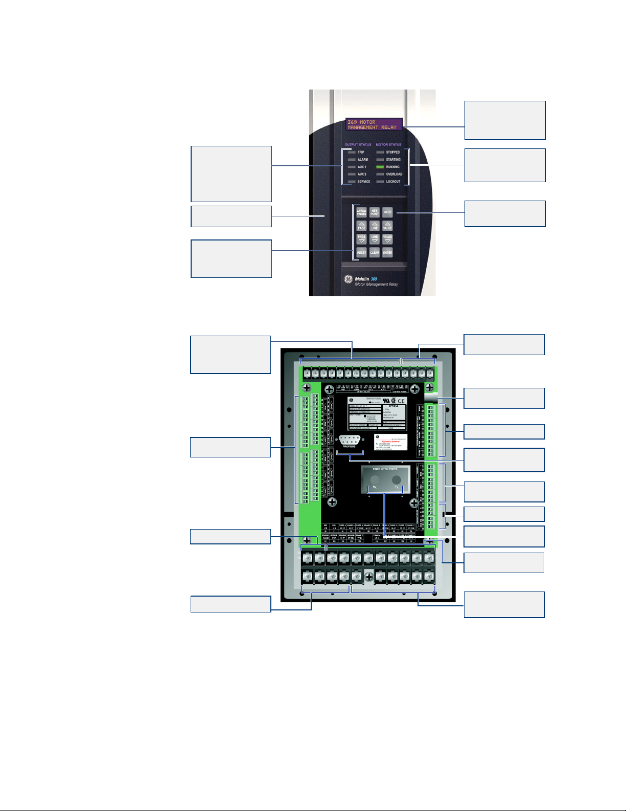
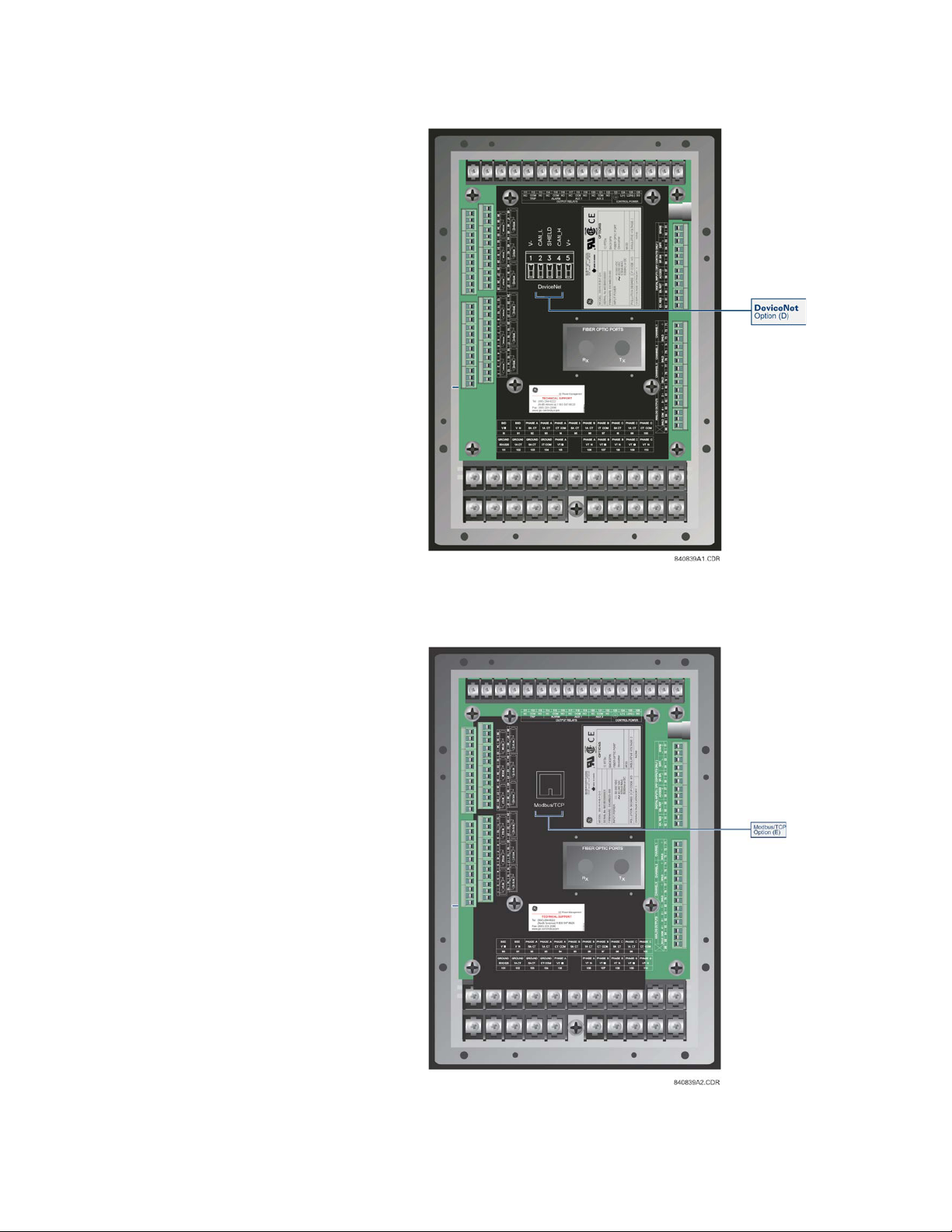
1.1.6 369 Relay Functional Summary
The front view for all 369 Relay models is shown below, along with the rear view showing
the Profibus port, the Modbus/TCP port, and the DeviceNet port .
369 MOTOR MANAGEMENT RELAY– INSTRUCTION MANUAL 1–5
ORDERING CHAPTER 1: INTRODUCTION
840702BM.CDR
FIBER OPTIC DATA LINK(F)
For harsh enviroments and or
hook up to RRTD
PROFIBUS-DP ( P )
PROFIBUS-DPV1 ( P1 )
BACKSPIN DETECTION(B)
20mV to 480V RMS
3 x RS485 Ports
3 Independent modbus
channels
1 ANALOG OUTPUT ( BASE UNIT )
3 ANALOG OUTPUTS (M,B)
VOLTAGE INPUTS(M)
0-240V wye or delta VT
connections.
GROUND CT INPUTS
5A, 1A and 50:0.25 taps
12 RTD INPUTS(R)
Field selectable type
CURRENT INPUTS
3 Phase CT inputs
5A, 1A, taps
CONTROL POWER
HI: 50-300 VDC/60-265 VAC
LO: 20-60 VDC / 20-48 VAC
4 OUTPUT RELAYS
Programmable alarm and trip
conditions activated by
programmable setpoints,
switch input, remote
communication control
Customer Accessible
Fuse
DIGITAL INPUTS
DISPLAY
40 Character alpha-numeric
LCD display for viewing
actual values, causes
of alarms and trips, and
programming setpoints
STATUS INDICATORS
LEDs indicate if motor is
stopped, starting, running,
overloaded or locked out
HELP KEY
Help key can be pressed at
any time to provide additional
information
KEYPAD
Used to select the display
of actual values, causes of
alarms, causes of trips, fault
diagnosis, and to program
setpoints
Rugged, corrosion and
flame retardent case.
STATUS INDICATORS
SERVICE LED
4 LEDs indicate when an
output is activated. When
an LED is lit, the cause of
the output relay operation
will be shown on the display.
indicates that a
self-diagnostic test failed, or
that the 369 is in Test Mode .
6
320
1–6 369 MOTOR MANAGEMENT RELAY– INSTRUCTION MANUAL
FIGURE 1–1: Front and Rear View
CHAPTER 1: INTRODUCTION ORDERING
FIGURE 1–2: DeviceNet Model
FIGURE 1–3: Rear View (Modbus/TCP Model)
369 MOTOR MANAGEMENT RELAY– INSTRUCTION MANUAL 1–7
ORDERING CHAPTER 1: INTRODUCTION
CE
g
INPUT POWER:
MODEL: 369-HI-R-B-F-P-0
MAXIMUM CONTACT RATING
250 VAC 8A RESISTIVE
1/4 HP 125VAC 1/2HP 250 VAC
SERIAL No: M53C07000001
FIRMWARE: 53CMC320.000
POLLUTION DEGREE: 2 IP CODE: 50X
50-300 VDC
60-265 VAC
485mA MAX.
50/60Hz or DC
MOD:
12 RTDs:
BACKSPIN
FIBER OPTIC PORT
PROFIBUS
OPTIONS
INSULATIVE VOLTAGE: 2
NONE
OVERVOLTAGE CATAGORY: II
1
7
2
8
3
9
4
10 11
56
12
840350AA.CDR
U
L
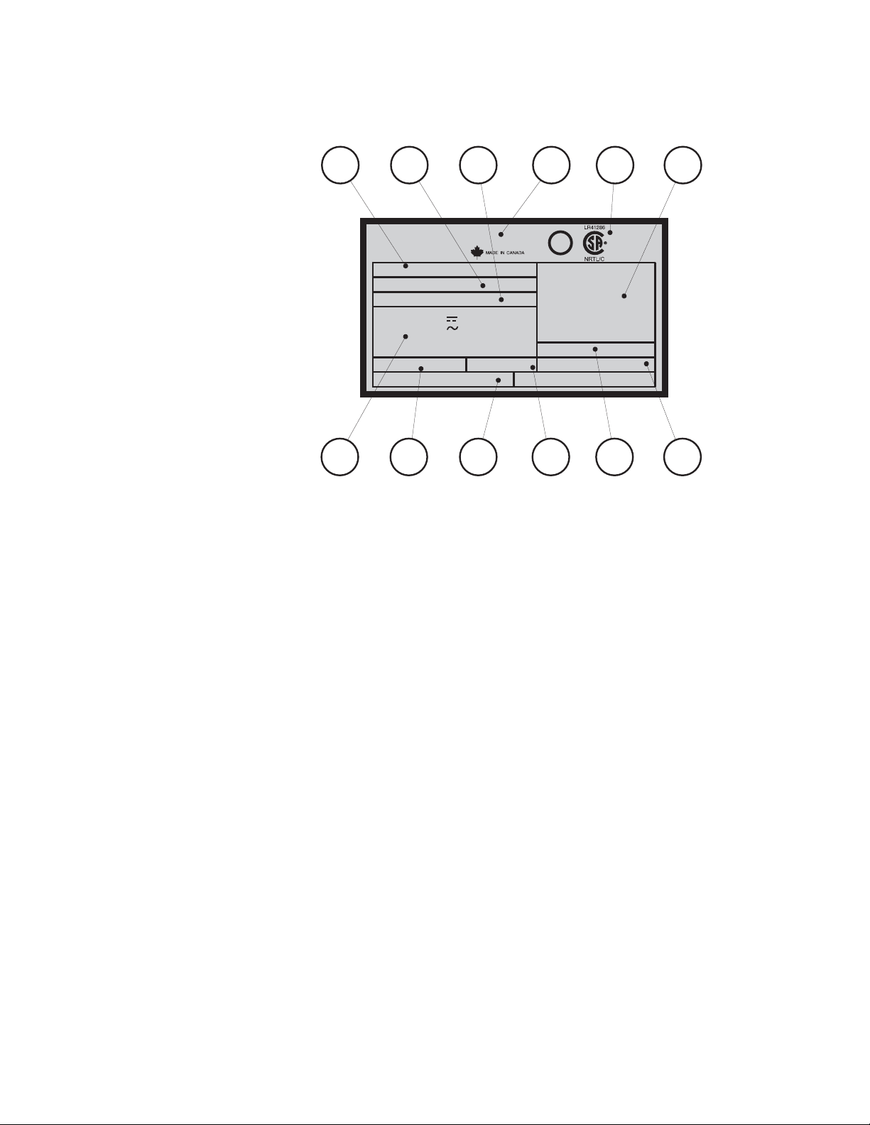
1.1.7 Relay Label Definition
1. The 369 Relay order code at the time of leaving the factory.
2. The serial number of the 369 Relay.
3. The firmware installed at the factory. Note that this may no longer be the currently
installed firmware as it may have been upgraded in the field. The current firmware revision can be checked in the actual values section of the 369 Relay.
4. Specifications for the output relay contacts.
5. Certifications the 369 Relay conforms with or has been approved to.
6. Factory installed options. These are based on the order code. Note that the 369 Relay
may have had options upgraded in the field. The actual values section of the 369 can
be checked to verify this.
7. Control power ratings for the 369 Relay as ordered. Based on the HI/LO rating from
the order code.
8. Pollution degree.
9. Overvoltage category.
10. IP code.
11. Modification number for any factory-ordered mods.
12. Insulative voltage rating.
1–8 369 MOTOR MANAGEMENT RELAY– INSTRUCTION MANUAL

Digital Energy
Multilin
2.1 Overview
369 Motor Management Relay
Chapter 2: Product Description
Product Description
2.1.1 Guideform Specifications
Motor protection and management shall be provided by a digital relay. Protective functions include:
• phase overload standard curves (51)
• overload by custom programmable curve (51)
2
•I
t modeling (49)
• current unbalance / single phase detection (46)
• starts per hour and time between starts
• short circuit (50)
• ground fault (50G/50N 51G/51N)
• mechanical jam / stall
• two-speed motor protection
Optional functions include:
• under / overvoltage (27/59)
•phase reversal (47)
• underpower (37)
• power factor (55)
• stator / bearing overtemperature with twelve (12) independent RTD inputs (49/38)
• backspin detection
Management functions include:
• statistical data
369 MOTOR MANAGEMENT RELAY– INSTRUCTION MANUAL 2–9

• pre-trip data (last 40 events)
• ability to learn, display and integrate critical parameters to maximize motor
protection
• a keypad with 40 character display
• flash memory
The relay is capable of displaying important metering functions, including phase voltages, kilowatts, kvars, power factor, frequency and MWhr. In addition, undervoltage
and low power factor alarm and trip levels are field programmable. The communications interface include one front RS232 port and three independent rear RS485 ports
with supporting PC software, thus allowing easy setpoint programming, local retrieval
of information and flexibility in communication with SCADA and engineering workstations.
2.1.2 Metered Quantities
Phase Currents and Current Demand Amps
Motor Load × FLA
Unbalance Current %
Ground Current Amps
Input Switch Status Open / Closed
Relay Output Status (De) Energized
RTD Temperature °C or °F R
Backspin Frequency Hz B
Phase/Line Voltages Volts M
Frequency Hz M
Power Factor lead / lag M
Real Power and Real Power Demand Watts M
Reactive Power and Reactive Power Demand Vars M
Apparent Power and Apparent Power Demand VA M
Real Power Consumption MWh M
Reactive Power Consumption/Generation ±Mvarh M
OVERVIEWCHAPTER 2: PRODUCT DESCRIPTION
METERED QUANTITY UNITS OPTION
2.1.3 Protection Features
ANSI/
IEEE
DEVICE
14 Speed Switch •
27 Undervoltage M • • •
37 Undercurrent / Underpower /M • •
38 Bearing RTD R or RRTD • •
46 Current Unbalance • •
47 Voltage Phase Reversal M •
49 Stator RTD R or RRTD • •
2–10 369 MOTOR MANAGEMENT RELAY– INSTRUCTION MANUAL
PROTECTION FEATURES OPTION TRIP ALARM BLOCK
START

CHAPTER 2: PRODUCT DESCRIPTIONOVERVIEW
ANSI/
IEEE
DEVICE
PROTECTION FEATURES OPTION TRIP ALARM BLOCK
50 Short Circuit & Backup •
50G/51G
Ground Fault & Ground Fault
Backup
••
51 Overload • • •
55 Power Factor M • •
59 Overvoltage M • •
66
Starts per Hour/Time
Between Starts
74 Alarm •
81 Over/Under Frequency M • •
86 Lockout •
87 Differential Switch •
General Switch • •
Reactive Power M • •
Thermal Capacity •
Start Inhibit (thermal capacity
available)
Restart Block (Backspin
Timer)
Mechanical Jam • •
Acceleration Timer •
Ambient RTD R or RRTD • •
Short/Low temp RTD R or RRTD •
Broken/Open RTD R or RRTD •
Loss of RRTD
Communications
RRTD •
Trip Counter •
Self Test/Service •
Backspin Detection B •
Current Demand •
kW Demand M •
kvar Demand M •
kVA Demand M •
Starter Failure •
Reverse Power M •
Undervoltage Autorestart M or B
START
•
•
•
369 MOTOR MANAGEMENT RELAY– INSTRUCTION MANUAL 2–11
2.1.4 Additional Features
OVERVIEWCHAPTER 2: PRODUCT DESCRIPTION
FEATURE OPTION
Modbus/TCP protocol Ethernet
interface
E
Profibus-DP rear communication port P
Profibus-DPV1 rear communication
port
P1
DeviceNet protocol interface D
User Definable Baud Rate (1200-
19200)
Flash Memory for easy firmware
updates
Front RS232 communication port
Rear RS485 communication port
Rear fiber optic port F
RTD type is user definable R or RRTD
4 User Definable Analog Outputs
(0 to 1 mA, 0 to 20 mA, 4 to 20 mA)
M
Windows based PC program for
setting up and monitoring
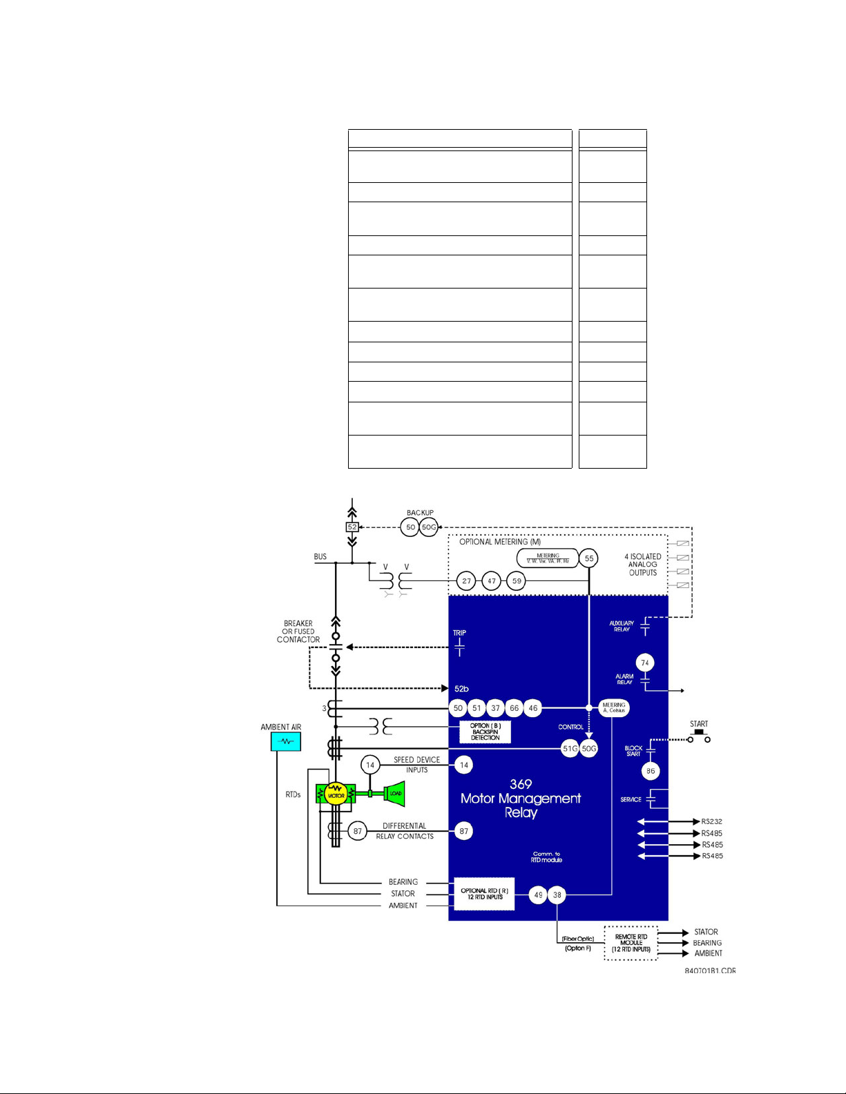
FIGURE 2–1: Single Line Diagram
2–12 369 MOTOR MANAGEMENT RELAY– INSTRUCTION MANUAL

2.2 Specifications
2.2.1 Inputs
CHAPTER 2: PRODUCT DESCRIPTIONSPECIFICATIONS
CONTROL POWER
LO range:............................................................DC: 20 to 60 V DC
AC: 20 to 48 V AC at 50/60 Hz
HI range:.............................................................DC: 50 to 300 V DC
AC: 60 to 265 V AC at 50/60 Hz
Power:..................................................................nominal: 20 VA; maximum: 65 VA
Holdup:................................................................non-failsafe trip: 200 ms; failsafe trip: 100 ms
FUSE
T 3.15 A H 250 V (5 × 20 mm)
Timelag high breaking capacity
PHASE CURRENT INPUTS (CT)
CT input (rated):...............................................1 A and 5 A secondary
CT primary:........................................................1 to 5000 A
Range:
for 50/60 Hz nominal frequency: ......0.05 to 20 × CT primary amps
for variable frequency: ...........................0.1 to 20 × CT primary amps
Full Scale: ...........................................................20 × CT primary amps or 65535 A maximum
Frequency:.........................................................20 to 100 Hz
Conversion: .......................................................True RMS, 1.04 ms/sample
Accuracy:
at ≤ 2 × CT:....................................................±0.5% of 2 × CT for 50/60 Hz nominal freq.
±1.0% of 2 × CT for variable frequency (for sinusoidal
waveforms)
at > 2 × CT:....................................................±1.0% of 20 × CT for 50/60 Hz nominal freq.
±3.0% of 12 × CT or less for variable frequency (for
sinusoidal waveforms)
PHASE CT BURDEN
PHASE CT INPUT (A) BURDEN
VA (Ω)
1 0.03 0.03
1A
5 0.64 0.03
20 11.7 0.03
5 0.07 0.003
5A
25 1.71 0.003
100 31 0.003
PHASE CT CURRENT WITHSTAND
PHASE CT WITHSTAND TIME
1s 2s continuous
1 A 100 × CT 40 × CT 3 × CT
5 A 100 × CT 40 × CT 3 × CT
DIGITAL / SWITCH INPUTS
Inputs:..................................................................6 optically isolated
Input type:..........................................................Dry Contact (< 800 Ω)
Function:.............................................................Programmable
369 MOTOR MANAGEMENT RELAY– INSTRUCTION MANUAL 2–13

SPECIFICATIONSCHAPTER 2: PRODUCT DESCRIPTION
GROUND CURRENT INPUT (GF CT)
CT Input (rated):...............................................1 A/5 A secondary and 50:0.025
CT Primary: ........................................................1 to 5000 A (1 A/5 A)
Range: .................................................................0.1 to 1.0 × CT primary (1 A/5 A)
0.05 to 25.0 A (50:0.025)
Full Scale: ...........................................................1.0 × CT primary (1 A/5 A)
25 A (50:0.025)
Frequency:.........................................................20 to 100 Hz
Conversion:........................................................True RMS 1.04ms/sample
Accuracy at 50/60 Hz:
for 1 A/5 A: .........................................±1.0% of full scale (1 A/5 A)
for 50:0.025........................................±0.07 A at <1 A
±0.20 A at <25 A
Accuracy at variable frequency:
for 1 A tap:.....................................................±1.5% for 40 to 100 Hz
±2.5% for 20 to 39 Hz
for 5 A tap:.....................................................±2% for 40 to 100 Hz
±3% for 20 to 39 Hz
for 50:0.025: .................................................±0.2 A at <1 A
±0.6 A at <25 A
GROUND CT BURDEN
GROUND CT INPUT (A) BURDEN
VA (Ω)
1 0.04 0.036
1A
5 0.78 0.031
20 6.79 0.017
5 0.07 0.003
5A
25 1.72 0.003
100 25 0.003
0.025 0.24 384
50:0.025
0.1 2.61 261
0.5 37.5 150
GROUND CT CURRENT WITHSTAND
GROUND CT WITHSTAND TIME
1s 2s continuous
1 A 100 × CT 40 × CT 3 × CT
5 A 100 × CT 40 × CT 3 × CT
50:0.025 10 A 5 A 150 mA
PHASE/LINE VOLTAGE INPUT (VT) (OPTION M)
VT ratio:...............................................................1.00 to 240.00:1 in steps of 0.01
VT secondary:...................................................240 V AC (full scale)
Range:..................................................................0.05 to 1.00 × full scale
Frequency:.........................................................20 to 100 Hz
Conversion:........................................................True RMS 1.04 ms/sample
Accuracy:...............................................±2.5% of full scale for ≤ 200 V at 20 to 39 Hz
±1% of full scale for 12 to 240 V at > 40 Hz
Burden:................................................................>200 kΩ
Max. continuous: ............................................280 V AC
2–14 369 MOTOR MANAGEMENT RELAY– INSTRUCTION MANUAL
2.2.2 Outputs
CHAPTER 2: PRODUCT DESCRIPTIONSPECIFICATIONS
BSD INPUTS (OPTION B)
Frequency: ........................................................1 to 120 Hz
Dynamic BSD range: ....................................20 mV to 480 V RMS
Accuracy:...............................................±0.02 Hz
Burden:................................................................>200 kΩ
RTD INPUTS (OPTION R)
Wire Type:..........................................................3 wire
Sensor Type: .....................................................100 Ω platinum (DIN 43760), 100 Ω nickel, 120 Ω nickel,
10 Ω copper
RTD sensing current: ....................................3 mA
Range:..................................................................–40 to 200°C or –40 to 392°F
Accuracy:...............................................±2°C or ±4°F
Lead resistance:..............................................25 Ω max. per lead for Pt and Ni type;
3 Ω max. per lead for Cu type
Isolation:.............................................................36 Vpk
ANALOG OUTPUTS (OPTION M)
PROGRAMMABLE
OUTPUT
MAX LOAD
MAX OUTPUT
Accuracy:...............................................±1% of full scale
Isolation:.............................................................fully isolated active source
0 to 1 mA 0 to 20 mA 4 to 20 mA
2400 Ω 600 Ω 600 Ω
1.01 mA 20.2 mA 20.2 mA
OUTPUT RELAYS
RESISTIVE
RATED LOAD
CARRY CURRENT
MAX SWITCHING
CAPACITY
MAX SWITCHING V
MAX SWITCHING I
OPERATE TIME
CONTACT
MATERIAL
LOAD (pf = 1)
8 A at 250 V AC
8A at 30VDC
8A
2000 VA
240 W
380 V AC; 125 V DC
8A 3.5A
<10 ms (5 ms typical)
silver alloy
LOAD (pf = 0.4)(L/
3.5 A at 250 V AC
3.5 A at 30 V DC
875 VA
170 W
INDUCTIVE
R – 7ms)
This equipment is suitable for use in Class 1, Div 2, Groups A, B, C, D or Non-Hazardous
Locations only if MOD502 is ordered.
Hazardous Location – Class 1, Div 2 output rating if MOD502 is ordered: 240 V, 3 A max,
as per UL1604. The contact rating is only for Make and carry operations, and shall not
be used for breaking DC current.
369 MOTOR MANAGEMENT RELAY– INSTRUCTION MANUAL 2–15

2.2.3 Metering
SPECIFICATIONSCHAPTER 2: PRODUCT DESCRIPTION
Explosion Hazard – Substitution of components may impair suitability for Class 1, Div 2.
Explosion Hazard – Do not disconnect equipment unless power has been switched off
or the area is known to be Non-Hazardous.
POWER METERING (OPTION M)
PARAMETERACCURAC
Y
(FULL SCALE)
RESOLUTIONRANGE
kW ±2% 1 kW ±32000
kvar ±2% 1 kvar ±32000
kVA ±2% 1 kVA 0 to 65000
kWh ±2% 1 kWh 0 to 999
MWh ±2% 1 MWh 0 to 65535
±kvarh ±2% 1 kvarh 0 to 999
±Mvarh ±2% 1 Mvarh 0 to 65535
Power Factor ±1% 0.01 –0.99 to 1.00
Frequency ±0.02 Hz 0.01 Hz
20.00 to
100.00
kW Demand ±2% 1 kW 0 to 32000
kvar Demand ±2% 1 kvar 0 to 32000
kVA Demand ±2% 1 kVA 0 to 65000
Amp Demand ±2% 1 A 0 to 65535
EVENT RECORD
Capacity:.............................................................last 512 events
Triggers:..............................................................trip, inhibit, power fail, alarms, self test,
waveform capture
WAVEFORM CAPTURE
Length:.................................................................3 buffers containing 16 cycles of all current and voltage
channels
Trigger position: ..............................................1 to 100% pre-trip to post-trip
Trigger: ...............................................................trip, manually via communications or digital input
MOTOR START DATA LOGGER
Length: ...............................................................6 Buffers containing 30 seconds of motor start data.
Trigger: ...............................................................Motor Start Status.
Trigger position: .............................................1-second pre-trigger duration.
Logging rate: ...................................................1 sample/200ms.
2–16 369 MOTOR MANAGEMENT RELAY– INSTRUCTION MANUAL

2.2.4 Communications
FRONT PORT
Type:.....................................................................RS232, non-isolated
Baud rate: ..........................................................4800 to 19200
Protocol:..............................................................Modbus
BACK PORTS (3)
Type:.....................................................................RS485
Baud rate: ..........................................................1200 to 19200
Protocol:..............................................................Modbus
36V isolation (together)
PROFIBUS (OPTIONS P AND P1)
Type:.....................................................................RS485
Baud rate: ..........................................................1200 baud to 12 Mbaud
Protocol:..............................................................Profibus-DP
Connector Type:..............................................DB9 Female
MODBUS/TCP ETHERNET (OPTION E)
Connector type:...............................................RJ45
Protocol:..............................................................Modbus/TCP
CHAPTER 2: PRODUCT DESCRIPTIONSPECIFICATIONS
®
RTU
®
RTU
Profibus-DPV1
DEVICENET (OPTION D)
DeviceNet CONFORMANCE TESTED™
Connector type:...............................................5-pin linear DeviceNet plug (phoenix type)
Baud rate: ..........................................................125, 250, and 500 kbps
Protocol:..............................................................DeviceNet
Bus-Side Current Draw:...............................85mA (Typical), 100mA (Max)
FIBER OPTIC PORT (OPTION F)
Optional use:.....................................................RTD remote module hookup
Baud rate: ..........................................................1200 to 19200
Protocol:..............................................................Modbus
®
RTU
Fiber sizes: .........................................................50/125, 62.5/125, 100/140, and 200 μm
Emitter fiber type: ..........................................820 nm LED, multimode
Link power budget:
Transmit power: ...........................................–20 dBm
Received sensitivity: ...................................–30 dBm
Power budget:...............................................10 dB
Maximum optical input power: ..............–7.6 dBm
Typical link distance: ...................................1.65 km
Note
Typical link distance is based upon the following assumptions for system loss. As actual
losses vary between installations, the distance covered will vary.
Connector loss: ..............................................2 dB
Fiber loss: ..........................................................3 dB/km
Splice loss: ........................................................One splice every 2 km at 0.05 dB loss/splice
System margin: ..............................................3 dB additional loss added to calculations to compensate
for all other losses
369 MOTOR MANAGEMENT RELAY– INSTRUCTION MANUAL 2–17

FIELDBUS LOSS OF COMMUNICATION
Pickup: .................................................................No communication
Time delay: ........................................................0.25 to 10 sec in steps of 0.25 sec
Timing accuracy:...................................±250 ms for Profibus
2.2.5 Protection Elements
51 OVERLOAD/STALL/THERMAL MODEL
Curve Shape: ....................................................1 to 15 standard, custom
Curve Biasing: ..................................................unbalance, temperature, hot/cold ratio,
Pickup Level: .....................................................1.01 to 1.25 × FLA
Pickup Accuracy: ............................................as per phase current inputs
Dropout Level:..................................................96 to 98% of pickup
Timing Accuracy:............................................±100 ms or ±2% of total trip time
THERMAL CAPACITY ALARM
Pickup Level: .....................................................1 to 100% TC in steps of 1
Pickup Accuracy: ............................................±2%
Dropout Level:..................................................96 to 98% of pickup
Timing Accuracy:............................................±100 ms
SPECIFICATIONSCHAPTER 2: PRODUCT DESCRIPTION
±300 ms for Ethernet
±250 ms for DeviceNet
cool time constants
OVERLOAD ALARM
Pickup Level: .....................................................1.01 to 1.50 × FLA in steps of 0.01
Pickup Accuracy: ............................................as per phase current inputs
Dropout Level:..................................................96 to 98% of pickup
Time Delay:........................................................0.1 to 60.0 s in steps of 0.1
Timing Accuracy:............................................±100 ms or ±2% of total trip time
50 SHORT CIRCUIT
Pickup Level: .....................................................2.0 to 20.0 × CT in steps of 0.1
Pickup Accuracy: ............................................as per phase current inputs
Dropout Level:..................................................96 to 98% of pickup
Time Delay:........................................................0 to 255.00 s in steps of 0.01 s
Backup Delay: ..................................................0.10 to 255.00 s in steps of 0.01 s
Timing Accuracy:............................................+50 ms for delays <50 ms
±100 ms or ±0.5% of total trip time
MECHANICAL JAM
Pickup Level: .....................................................1.01 to 6.00 × FLA in steps of 0.01
Pickup Accuracy: ............................................as per phase current inputs
Dropout Level:..................................................96 to 98% of pickup
Time Delay:........................................................0.5 to 125.0 s in steps of 0.5
Timing Accuracy:............................................±250 ms or ±0.5% of total trip time
37 UNDERCURRENT
Pickup Level: .....................................................0.10 to 0.99 × FLA in steps of 0.01
Pickup Accuracy: ............................................as per phase current inputs
Dropout Level:..................................................102 to 104% of pickup
Time Delay:........................................................1 to 255 s in steps of 1
Start Delay:........................................................0 to 15000 s in steps of 1
Timing Accuracy:............................................±500 ms or ±0.5% of total time
2–18 369 MOTOR MANAGEMENT RELAY– INSTRUCTION MANUAL

CHAPTER 2: PRODUCT DESCRIPTIONSPECIFICATIONS
46 UNBALANCE
Pickup Level:.....................................................4 to 30% in steps of 1
Pickup Accuracy: ............................................±2%
Dropout Level:..................................................1 to 2% below pickup
Time Delay: .......................................................1 to 255 s in steps of 1
Start Delay:........................................................0 to 5000 s in steps of 1
Timing Accuracy:............................................±500 ms or ±0.5% of total time
50G/51G 50N/51N GROUND FAULT
Pickup Level:.....................................................0.10 to 1.00 × CT for 1 A/5 A CT
0.25 to 25.00 A for 50:0.025 CT
Pickup Accuracy:............................................as per ground current inputs
Dropout Level:..................................................96 to 98% of pickup
Time Delay: .......................................................0 to 255.00 s in steps of 0.01 s
Backup Delay:..................................................0.01 to 255.00 s in steps of 0.01 s
Timing Accuracy:............................................+50 ms for delays <50 ms
±100 ms or ±0.5% of total trip time
ACCELERATION TRIP
Pickup Level:.....................................................motor start condition
Dropout Level:..................................................motor run, trip or stop condition
Time Delay: .......................................................1.0 to 250.0 s in steps of 0.1
Timing Accuracy:............................................±100 ms or ±0.5% of total time
38/49 RTD AND RRTD PROTECTION
Pickup Level:.....................................................1 to 200°C or 34 to 392°F
Pickup Accuracy:................................... ±2°C or ±4°F
Dropout Level:..................................................96 to 98% of pickup above 80°C
Time Delay: .......................................................<5 s
OPEN RTD ALARM
Pickup Level:.....................................................detection of an open RTD
Pickup Accuracy: ............................................>1000 Ω
Dropout Level:..................................................96 to 98% of pickup
Time Delay: .......................................................<5 s
SHORT/LOW TEMP RTD ALARM
Pickup Level:.....................................................<–40°C or –40°F
Pickup Accuracy:................................... ±2°C or ±4°F
Dropout Level:..................................................96 to 98% of pickup
Time Delay: .......................................................<5 s
LOSS OF RRTD COMMS ALARM
Pickup Level:.....................................................no communication
Time Delay: .......................................................2 to 5 s
27 UNDERVOLTAGE
Pickup Level:.....................................................0.50 to 0.99 × rated in steps of 0.01
Pickup Accuracy:............................................as per phase voltage inputs
Dropout Level:..................................................102 to 104% of pickup
Time Delay: .......................................................0.0 to 255.0 s in steps of 0.1
Start Delay:........................................................separate level for start conditions
Timing Accuracy:............................................+75 ms for delays <50 ms
±100 ms or ±0.5% of total trip time
59 OVERVOLTAGE
Pickup Level:.....................................................1.01 to 1.25 × rated in steps of 0.01
Pickup Accuracy:............................................as per phase voltage inputs
369 MOTOR MANAGEMENT RELAY– INSTRUCTION MANUAL 2–19

SPECIFICATIONSCHAPTER 2: PRODUCT DESCRIPTION
Dropout Level:..................................................96 to 98% of pickup
Time Delay:........................................................0.0 to 255.0 s in steps of 0.1
Timing Accuracy:............................................±100 ms or ±0.5% of total trip time
47 PHASE REVERSAL
Pickup Level: .....................................................phase reversal detected
Time Delay:........................................................500 to 700 ms
81 UNDERFREQUENCY
Pickup Level: .....................................................20.00 to 70.00 Hz in steps of 0.01
Pickup Accuracy: ............................................±0.02 Hz
Dropout Level:..................................................0.05 Hz
Time Delay:........................................................0.0 to 255.0 s in steps of 0.1
Start Delay:........................................................0 to 5000 s in steps of 1
Timing Accuracy:............................................±100 ms or ±0.5% of total trip time
81 OVERFREQUENCY
Pickup Level: .....................................................20.00 to 70.00 Hz in steps of 0.01
Pickup Accuracy: ............................................±0.02 Hz
Dropout Level:..................................................0.05 Hz
Time Delay:........................................................0.0-255.0 s in steps of 0.1
Start Delay:........................................................0-5000 s in steps of 1
Timing Accuracy:............................................±100 ms or ±0.5% of total trip time
55 LEAD POWER FACTOR
Pickup Level: .....................................................0.99 to 0.05 in steps of 0.01
Pickup Accuracy: ............................................±0.02
Dropout Level:..................................................0.03 of pickup
Time Delay:........................................................0.1 to 255.0 s in steps of 0.1
Start Delay:........................................................0 to 5000 s in steps of 1
Timing Accuracy:............................................±300 ms or ±0.5% of total trip time
55 LAG POWER FACTOR
Pickup Level: .....................................................0.99 to 0.05 in steps of 0.01
Pickup Accuracy: ............................................±0.02
Dropout Level:..................................................0.03 of pickup
Time Delay:........................................................0.1 to 255.0 s in steps of 0.1
Start Delay:........................................................0 to 5000 s in steps of 1
Timing Accuracy:............................................±300 ms or ±0.5% of total trip time
POSITIVE REACTIVE POWER
Pickup Level: .....................................................1 to 25000 in steps of 1
Pickup Accuracy: ............................................±2%
Dropout Level:..................................................96 to 98% of pickup
Time Delay:........................................................0.1 to 255.0 s in steps of 0.1
Start Delay:........................................................0 to 5000 s in steps of 1
Timing Accuracy:............................................±300 ms or ±0.5% of total trip time
NEGATIVE REACTIVE POWER
Pickup Level: .....................................................1 to 25000 kvar in steps of 1
Pickup Accuracy: ............................................±2%
Dropout Level:..................................................96 to 98% of pickup
Time Delay:........................................................0.1 to 255.0 s in steps of 0.1
Start Delay:........................................................0 to 5000 s in steps of 1
Timing Accuracy:............................................±300 ms or ±0.5% of total trip time
37 UNDERPOWER
Pickup Level: .....................................................1 to 25000 kW in steps of 1
Pickup Accuracy: ............................................±2%
2–20 369 MOTOR MANAGEMENT RELAY– INSTRUCTION MANUAL

CHAPTER 2: PRODUCT DESCRIPTIONSPECIFICATIONS
Dropout Level:..................................................102 to 104% of pickup
Time Delay: .......................................................0.5 to 255.0 s in steps of 0.5
Start Delay:........................................................0 to 15000 s in steps of 1
Timing Accuracy:............................................±300 ms or ±0.5% of total trip time
REVERSE POWER
Pickup Level:.....................................................1 to 25000 kW in steps of 1
Pickup Accuracy: ............................................±2%
Dropout Level:..................................................96 to 98% of pickup
Time Delay: .......................................................0.5 to 30.0 s in steps of 0.5
Start Delay:........................................................0 to 50000 s in steps of 1
Timing Accuracy:............................................±300 ms or ±0.5% of total trip time
87 DIFFERENTIAL SWITCH
Time Delay: .......................................................<200 ms
14 SPEED SWITCH
Time Delay: .......................................................0.5 to 100.0 s in steps of 0.5
Timing Accuracy:............................................±200 ms or ±0.5% of total trip time
GENERAL SWITCH
Time Delay: .......................................................0.1 to 5000.0 s in steps of 0.1
Start Delay:........................................................0 to 5000 s in steps of 1
Timing Accuracy:............................................±200 ms or ±0.5% of total trip time
DIGITAL COUNTER
Pickup: .................................................................on count equaling level
Time Delay: .......................................................<200 ms
BACKSPIN DETECTION
Dynamic BSD:...................................................20 mV to 480 V RMS
Pickup Level:.....................................................3 to 120 Hz in steps of 1
Dropout Level:..................................................2 to 30 Hz in steps of 1
Level Accuracy: ...............................................±0.02 Hz
Timing Accuracy:............................................±500 ms or ±0.5% of total trip time
2.2.6 Monitoring Elements
STARTER FAILURE
Pickup level: ......................................................motor run condition when tripped
Dropout level:...................................................motor stopped condition
Time delay: ........................................................10 to 1000 ms in steps of 10
Timing accuracy:............................................±100 ms
CURRENT DEMAND ALARM
Demand period:..............................................5 to 90 min. in steps of 1
Pickup level: ......................................................0 to 65000 A in steps of 1
Pickup accuracy: ............................................as per phase current inputs
Dropout level:...................................................96 to 98% of pickup
Time delay: ........................................................<2 min.
kW DEMAND ALARM
Demand period:..............................................5 to 90 min. in steps of 1
Pickup level: ......................................................1 to 50000 kW in steps of 1
Pickup accuracy: ............................................±2%
Dropout level:...................................................96 to 98% of pickup
Time delay: ........................................................<2 min.
kvar DEMAND ALARM
Demand period:..............................................5 to 90 min. in steps of 1
369 MOTOR MANAGEMENT RELAY– INSTRUCTION MANUAL 2–21

Pickup level:.......................................................1 to 50000 kvar in steps of 1
Pickup accuracy:.............................................±2%
Dropout level:...................................................96 to 98% of pickup
Time delay: ........................................................<2 min.
kVA DEMAND ALARM
Demand period: ..............................................5 to 90 min in steps of 1
Pickup level:.......................................................1 to 50000 kVA in steps of 1
Pickup accuracy:.............................................±2%
Dropout level:...................................................96 to 98% of pickup
Time delay: ........................................................<2 min.
TRIP COUNTER
Pickup: .................................................................on count equaling level
Time delay: ........................................................<200 ms
2.2.7 Control Elements
REDUCED VOLTAGE START
Transition Level:..............................................25 to 300% FLA in steps of 1
Transition Time:...............................................1 to 250 sec. in steps of 1
Transition Control:..........................................Current, Timer, Current and Timer
UNDERVOLTAGE AUTORESTART
Pickup/Restoration level: ...........................0.50 to 1.00 × rated in steps of 0.01
Immediate Restart Power Loss Time: ..100 to 500 ms in steps of 100ms
Delay 1 Restart Power Loss Time: .........0.1 to 10 s in steps of 0.1 s, or OFF.
Delay 1 Restart Time Delay: .....................0 to 1200.0 s in steps of 0.2 s
Delay 2 Restart Power Loss Time: ........1 to 3600s in steps of 1s, Off or Unlimited
Delay 2 Restart Time Delay: .....................0 to 1200.0 s in steps of 0.2 s
Time Accuracy: ...............................................± 200ms
SPECIFICATIONSCHAPTER 2: PRODUCT DESCRIPTION
1 to 9 seconds (with loss of control power)
2.2.8 Environmental Specifications
AMBIENT TEMPERATURE
Operating Range: ..........................................-40°C to +60°C
Storage Range: ...............................................-40°C to +80°C
T-Code Rating: .................................................T4A (for MOD 502 only)
NoteNOTE:
2–22 369 MOTOR MANAGEMENT RELAY– INSTRUCTION MANUAL
For 369 units with the Profibus, Modbus/TCP, or DeviceNet option the operating and
storage ranges are as follows:
Operating Range: ..........................................+5°C to +60°C
Storage Range: ...............................................+5°C to +80°C
HUMIDITY
Up to 95% non condensing
DUST/MOISTURE
IP50
VENTILATION
No special ventilation required as long as ambient temperature remains within specifications.
Ventilation may be required in enclosures exposed to direct sunlight.

OVERVOLTAGE CATEGORY II
CLEANING
May be cleaned with a damp cloth.
2.2.9 Long-term storage
LONG-TERM STORAGE
Environment: ...................................................In addition to the above environmental considerations,
Correct storage:..............................................Prevents premature component failures caused by
CHAPTER 2: PRODUCT DESCRIPTIONSPECIFICATIONS
the relay should be stored in an environment that is dry,
corrosive-free, and not in direct sunlight.
environmental factors such as moisture or corrosive
gases. Exposure to high humidity or corrosive
environments will prematurely degrade the electronic
components in any electronic device regardless of its use
or manufacturer, unless specific precautions, such as
those mentioned in the Environmental section above, are
taken.
Note
It is recommended that all relays be powered up once per year, for one hour
continuously, to avoid deterioration of electrolytic capacitors and subsequent relay
failure.
2.2.10 Approvals/Certification
ISO:........................................................................Designed and manufactured to an ISO9001 registered
process.
UL:..........................................................................UL Listed (File E234799*)
(File E83849)
UL 508 - Industrial Control Equipment
UL 1053 - Ground Fault Protection Equipment
UL 1604* - Electrical Equipment for use in Class 1 Div 2
Hazardous Locations
CSA:.......................................................................Certified per: C22.2 No. 142 - Process Control Equipment
C22.2 No. 213* - Non-incendive Electrical Equipment for
use in class 1 Div 2 Hazardous Locations
CE:..........................................................................Conforms to EN 55011/CISPR 11, EN50082-2, IEC 947-1,
1010-1
* For MOD502 only
DeviceNet CONFORMANCE TESTED™
2.2.11 Type Test Standards
SURGE WITHSTAND CAPABILITY
ANSI/IEEE C37.90.1 Oscillatory (2.5 kV/1 MHz)
ANSI/IEEE C37.90.1 Fast Rise (5 kV/10 ns)
IEC / EN 61000-4-4, Level 4
INSULATION RESISTANCE
IEC / EN 60255-5
369 MOTOR MANAGEMENT RELAY– INSTRUCTION MANUAL 2–23

SPECIFICATIONSCHAPTER 2: PRODUCT DESCRIPTION
IMPULSE TEST
IEC / EN 60255-5
DIELECTRIC STRENGTH: ...............................ANSI/IEEE C37.90
IEC / EN 60255-5
CSA C22.2 No.14
ELECTROSTATIC DISCHARGE
EN 61000-4-2, Level 2
IEC 60255-22-2 Level 2
SURGE IMMUNITY
IEC 1000-4-5, EN 61000-4-5
IEC 60255-22-5
CURRENT WITHSTAND
ANSI/IEEE C37.90
IEC 60255-6
RFI
ANSI/IEEE C37.90.2, 35 V/m
EN 61000-4-3 10V/m
CONDUCTED IMMUNITY:.............................IEC 1000-4-6
IEC 60255-22-6
CONDUCTED/RADIATED EMISSIONS
EN 55011 (IEC CISPR 11)
ENVIRONMENTAL
ANSI/IEEE C37.90
IEC 60255-6
IEC 60068-2-38 Part 2
IEC60068-2-1, 16h at -40°C
IEC60068-2-2, 16h at +85°C
IEC60068-2-30, 95% variant 1, 6 days
VIBRATION
IEC 60255-21-1 Class 1
IEC 60255-21-2 Class 1
VOLTAGE DEVIATION
IEC 1000-4-11 / EN 61000-4-11
MAGNETIC FIELD IMMUNITY
IEC 1000-4-8 / EN61000-4-8
T-CODE RATING
T4A
2.2.12 Production Tests
DIELECTRIC STRENGTH
2200 VAC for 1 second (as per UL & CE)
BURN IN
8 hours at 60°C sampling plan
CALIBRATION AND FUNCTIONALITY
100% hardware functionality tested
100% calibration of all metered quantities
2–24 369 MOTOR MANAGEMENT RELAY– INSTRUCTION MANUAL

Digital Energy
Multilin
369 Motor Management Relay
Chapter 3: Installation
Installation
3.1 Mechanical Installation
3.1.1 Mechanical Installation
The 369 is contained in a compact plastic housing with the keypad, display,
communication port, and indicators/targets on the front panel. The unit should be
positioned so the display and keypad are accessible. To mount the relay, make cutout and
drill mounting holes as shown below. Mounting hardware (bolts and washers) is provided
with the relay. Although the relay is internally shielded to minimize noise pickup and
interference, it should be mounted away from high current conductors or sources of
strong magnetic fields.
FIGURE 3–1: Physical Dimensions
369 MOTOR MANAGEMENT RELAY– INSTRUCTION MANUAL 3–27

MECHANICAL INSTALLATION CHAPTER 3: INSTALLATION
FIGURE 3–2: Split Mounting Dimensions
3–28 369 MOTOR MANAGEMENT RELAY– INSTRUCTION MANUAL

CHAPTER 3: INSTALLATION TERMINAL IDENTIFICATION
3.2 Terminal Identification
3.2.1 369 Relay Terminal List
TERMINAL WIRING CONNECTION
1RTD1 +
2RTD1 –
3 RTD1 COMPENSATION
4RTD1 SHIELD
5RTD2 +
6RTD2 –
7 RTD2 COMPENSATION
8RTD2 SHIELD
9RTD3 +
10 RTD3 –
11 RTD3 COMPENSATION
12 RTD3 SHIELD
13 RTD4 +
14 RTD4 –
15 RTD4 COMPENSATION
16 RTD4 SHIELD
17 RTD5 +
18 RTD5 –
19 RTD5 COMPENSATION
20 RTD5 SHIELD
21 RTD6 +
22 RTD6 –
23 RTD6 COMPENSATION
24 RTD6 SHIELD
25 RTD7 +
26 RTD7 –
27 RTD7 COMPENSATION
28 RTD7 SHIELD
29 RTD8 +
30 RTD8 –
31 RTD8 COMPENSATION
32 RTD8 SHIELD
33 RTD9 +
34 RTD9 –
35 RTD9 COMPENSATION
36 RTD9 SHIELD
37 RTD10 +
38 RTD10 –
39 RTD10 COMPENSATION
40 RTD10 SHIELD
41 RTD11 +
42 RTD11 –
43 RTD11 COMPENSATION
369 MOTOR MANAGEMENT RELAY– INSTRUCTION MANUAL 3–29

TERMINAL IDENTIFICATION CHAPTER 3: INSTALLATION
TERMINAL WIRING CONNECTION
44 RTD11 SHIELD
45 RTD12 +
46 RTD12 –
47 RTD12 COMPENSATION
48 RTD12 SHIELD
51 SPARE SW
52 SPARE SW COMMON
53 DIFFERENTIAL INPUT SW
54 DIFFERENTIAL INPUT SW COMMON
55 SPEED SW
56 SPEED SW COMMON
57 ACCESS SW
58 ACCESS SW COMMON
59 EMERGENCY RESTART SW
60 EMERGENCY RESTART SW COMMON
61 EXTERNAL RESET SW
62 EXTERNAL RESET SW COMMON
71 COMM1 RS485 +
72 COMM1 RS485 –
73 COMM1 SHIELD
74 COMM2 RS485 +
75 COMM2 RS485 –
76 COMM2 SHIELD
77 COMM3 RS485 +
78 COMM3 RS485 –
79 COMM3 SHIELD
80 ANALOG OUT 1
81 ANALOG OUT 2
82 ANALOG OUT 3
83 ANALOG OUT 4
84 ANALOG COM
85 ANALOG SHIELD
90 BACKSPIN VOLTAGE
91 BACKSPIN NEUTRAL
92 PHASE A CURRENT 5A
93 PHASE A CURRENT 1A
94 PHASE A COMMON
95 PHASE B CURRENT 5A
96 PHASE B CURRENT 1A
97 PHASE B COMMON
98 PHASE C CURRENT 5A
99 PHASE C CURRENT 1A
100 PHASE C COMMON
101 NEUT/GND CURRENT 50:0.025A
102 NEUT/GND CURRENT 1A
103 NEUT/GND CURRENT 5A
104 NEUT/GND COMMON
105 PHASE A VOLTAGE
106 PHASE A NEUTRAL
3–30 369 MOTOR MANAGEMENT RELAY– INSTRUCTION MANUAL

CHAPTER 3: INSTALLATION TERMINAL IDENTIFICATION
TERMINAL WIRING CONNECTION
107 PHASE B VOLTAGE
108 PHASE B NEUTRAL
109 PHASE C VOLTAGE
110 PHASE C NEUTRAL
111 TRIP NC
112 TRIP COMMON
113 TRIP NO
114 ALARM NC
115 ALARM COMMON
116 ALARM NO
117 AUX1 NC
118 AUX1 COMMON
119 AUX1 NO
120 AUX2 NC
121 AUX2 COMMON
122 AUX2 NO
123 POWER FILTER GROUND
124 POWER LINE
125 POWER NEUTRAL
126 POWER SAFETY
3.2.2 269 to 369 Relay Conversion Terminal List
269 WIRING CONNECTION 369
1RTD1 + 1
2 RTD1 COMPENSATION 3
3RTD1 – 2
4RTD1 SHIELD 4
5RTD2 + 5
6 RTD2 COMPENSATION 7
7RTD2 – 6
8RTD2 SHIELD 8
9RTD3 + 9
10 RTD3 COMPENSATION 11
11 RTD3 – 10
12 RTD3 SHIELD 12
71 RTD4 + 13
70 RTD4 COMPENSATION 15
69 RTD4 – 14
68 RTD4 SHIELD 16
67 RTD5 + 17
66 RTD5 COMPENSATION 19
65 RTD5 – 18
64 RTD5 SHIELD 20
63 RTD6 + 21
369 MOTOR MANAGEMENT RELAY– INSTRUCTION MANUAL 3–31

TERMINAL IDENTIFICATION CHAPTER 3: INSTALLATION
269 WIRING CONNECTION 369
62 RTD6 COMPENSATION 23
61 RTD6 – 22
60 RTD6 SHIELD 24
13 RTD7 + 25
14 RTD7 COMPENSATION 27
15 RTD7 – 26
16 RTD7 SHIELD 28
17 RTD8 + 29
18 RTD8 COMPENSATION 31
19 RTD8 – 30
20 RTD8 SHIELD 32
21 RTD9 + 33
22 RTD9 COMPENSATION 35
23 RTD9 – 34
24 RTD9 SHIELD 36
25 RTD10 + 37
26 RTD10 COMPENSATION 39
27 RTD10 – 38
28 RTD10 SHIELD 40
44 SPARE SW 51
45 SPARE SW COMMON 52
48 DIFFERENTIAL INPUT SW 53
49 DIFFERENTIAL INPUT SW COMMON 54
50 SPEED SW 55
51 SPEED SW COMMON 56
52 ACCESS SW 57
53 ACCESS SW COMMON 58
54 EMERGENCY RESTART SW 59
55 EMERGENCY RESTART SW COM 60
56 EXTERNAL RESET SW 61
57 EXTERNAL RESET SW COMMON 62
47 COMM1 RS485 + 71
46 COMM1 RS485 – 72
88 COMM1 SHIELD 73
59 ANALOG OUT 1 80
58 ANALOG COMMON 84
83 PHASE A CURRENT 1A 93
82 PHASE A COMMON 94
81 PHASE A CURRENT 5A 92
80 PHASE B CURRENT 1A 96
79 PHASE B COMMON 97
78 PHASE B CURRENT 5A 95
77 PHASE C CURRENT 1A 99
3–32 369 MOTOR MANAGEMENT RELAY– INSTRUCTION MANUAL

CHAPTER 3: INSTALLATION TERMINAL IDENTIFICATION
269 WIRING CONNECTION 369
76 PHASE C COMMON 100
75 PHASE C CURRENT 5A 98
73 NEUTRAL/GROUND COMMON 104
72 NEUTRAL/GROUND CURRENT 5A 103
74 NEUT/GND CURRENT 50:0.025A 101
29 TRIP NC 111
30 TRIP COMMON 112
31 TRIP NO 113
32 ALARM NC 114
33 ALARM COMMON 115
34 ALARM NO 116
35 AUX1 NC 117
36 AUX1 COMMON 118
37 AUX1 NO 119
38 AUX2 NC 120
39 AUX2 COMMON 121
40 AUX2 NO 122
42 POWER FILTER GROUND 123
41 POWER LINE 124
43 POWER NEUTRAL 125
Terminals not available on the 369
84 MTM B+ N/A
85 MTM A– N/A
369 MOTOR MANAGEMENT RELAY– INSTRUCTION MANUAL 3–33

TERMINAL IDENTIFICATION CHAPTER 3: INSTALLATION
3.2.3 MTM-369 Relay Conversion Terminal List
MTM WIRING CONNECTION 369
1 POWER FILTER GROUND 123
2PHASE A VOLTAGE 105
3PHASE B VOLTAGE 107
4PHASE B VOLTAGE 107
5PHASE C VOLTAGE 109
6PHASE A COM 94
7 PHASE A CURRENT 5A 92
8 PHASE A CURRENT 1A 93
9PHASE B COM 97
10 PHASE B CURRENT 5A 95
11 PHASE B CURRENT 1A 96
12 PHASE C COM 100
13 PHASE C CURRENT 5A 98
14 PHASE C CURRENT 1A 99
15 COMM1 RS485 + 71
16 COMM1 RS485 – 72
17 COMM1 SHIELD 73
18 ANALOG OUT 1 80
19 ANALOG OUT1 COM 84
20 ANALOG OUT 2 81
21 ANALOG OUT 2 COM 84
22 ANALOG OUT 3 82
23 ANALOG OUT 3 COM 84
24 ANALOG OUT 4 83
25 ANALOG OUT 4 COM 84
26 ANALOG SHIELD 85
27 ALARM NC 114
28 ALARM COM 115
29 ALARM NO 116
31 SPARE SW 51
32 SPARE SW COM 52
34 POWER LINE 124
35 POWER NEUTRAL 125
Terminals not available on the 369:
30 PULSE OUTPUT (P/O) N/A
33 SW.B N/A
3–34 369 MOTOR MANAGEMENT RELAY– INSTRUCTION MANUAL

CHAPTER 3: INSTALLATION TERMINAL IDENTIFICATION
3.2.4 MPM-369 Relay Conversion Terminal List
MPM WIRING CONNECTION 369
1 PHASE A VOLTAGE 105
2 PHASE B VOLTAGE 107
3 PHASE C VOLTAGE 109
4 PHASE NEUTRAL 108
5 POWER FILTER GROUND 123
6 POWER SAFETY 126
7 POWER NEUTRAL 125
8 POWER LINE 124
9 PHASE A CURRENT 5A 92
10 PHASE A CURRENT 1A 93
11 PHASE A COM 94
12 PHASE B CURRENT 5A 95
13 PHASE B CURRENT 1A 96
14 PHASE B COM 97
15 PHASE C CURRENT 5A 98
16 PHASE C CURRENT 1A 99
17 PHASE C COM 100
28 ANALOG OUT 1 80
27 ANALOG OUT 2 81
26 ANALOG OUT 3 82
25 ANALOG OUT 4 83
24 ANALOG COM 84
21 ANALOG SHIELD 85
43 ALARM NC 114
44 ALARM COM 115
45 ALARM NO 116
46 COMM1 SHIELD 73
47 COMM1 RS485 – 72
48 COMM1 RS485 + 71
Terminals not available on the 369
31 SWITCH INPUT 1 N/A
32 SWITCH INPUT 2 N/A
33 SWITCH COM N/A
369 MOTOR MANAGEMENT RELAY– INSTRUCTION MANUAL 3–35

TERMINAL IDENTIFICATION CHAPTER 3: INSTALLATION
3.2.5 Terminal Layout
FIGURE 3–3: TERMINAL LAYOUT
3–36 369 MOTOR MANAGEMENT RELAY– INSTRUCTION MANUAL

CHAPTER 3: INSTALLATION ELECTRICAL INSTALLATION
3.3 Electrical Installation
3.3.1 Typical Wiring Diagram
FIGURE 3–4: Typical Wiring for Motor Forward/Reversing Application
3.3.2 Typical Wiring
The 369 can be connected to cover a broad range of applications and wiring will vary
depending upon the user’s protection scheme. This section will cover most of the typical
369 interconnections.
369 MOTOR MANAGEMENT RELAY– INSTRUCTION MANUAL 3–37

ELECTRICAL INSTALLATION CHAPTER 3: INSTALLATION
In this section, the terminals have been logically grouped together for explanatory
purposes. A typical wiring diagram for the 369 is shown above in FIGURE 3–4: Typical
Wiring for Motor Forward/Reversing Application on page 3–37 and the terminal
arrangement has been detailed in FIGURE 3–3: TERMINAL LAYOUT on page 3–36. For
further information on applications not covered here, refer to Chapter : Applications or
contact the factory for further information.
Hazard may result if the product is not used for intended purposes. This equipment can
only be serviced by trained personnel.
Do not run signal wires in the same conduit or bundle that carries power mains or high
level voltage or currents.
3.3.3 Control Power
VERIFY THAT THE CONTROL POWER SUPPLIED TO THE RELAY IS WITHIN THE RANGE
COVERED BY THE ORDERED 369 RELAY’S CONTROL POWER.
Table 3–1: 369 POWER SUPPLY RANGES
369 POWER SUPPLY AC RANGE DC RANGE
HI 60 to 265 V 50 to 300 V
LO 20 to 48 V 20 to 60 V
The 369 has a built-in switchmode supply. It can operate with either AC or DC voltage
applied to it. The relay reboot time of the 369 is 2 seconds after the control power is
applied. For applications where the control power for the 369 is available from the same
AC source as that of the motor, it is recommended an uninterrupted power supply be used
to power up the relay or, alternatively, use a separate DC source to power up.
Extensive filtering and transient protection has been incorporated into the 369 to ensure
reliable operation in harsh industrial environments. Transient energy is removed from the
relay and conducted to ground via the ground terminal. This terminal must be connected
to the cubicle ground bus using a 10 AWG wire or a ground braid. Do not daisy-chain
grounds with other relays or devices. Each should have its own connection to the ground
bus.
The internal supply is protected via a 3.15 A slo-blo fuse that is accessible for replacement.
If it must be replaced ensure that it is replaced with a fuse of equal size (see FUSE on page
2–13).
3.3.4 Phase Current (CT) Inputs
The 369 requires one CT for each of the three motor phase currents to be input into the
relay. There are no internal ground connections for the CT inputs. Refer to Chapter :
Applications for information on two CT connections.
3–38 369 MOTOR MANAGEMENT RELAY– INSTRUCTION MANUAL
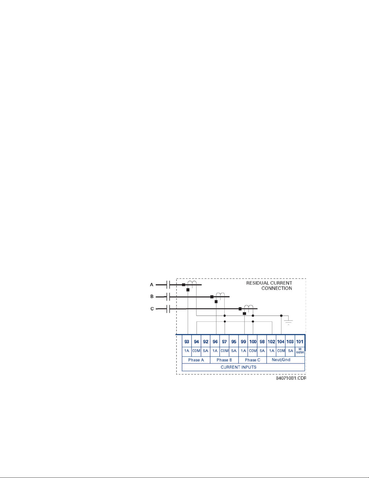
CHAPTER 3: INSTALLATION ELECTRICAL INSTALLATION
The phase CTs should be chosen such that the FLA of the motor being protected is no less
than 50% of the rated CT primary. Ideally, to ensure maximum accuracy and resolution,
the CTs should be chosen such that the FLA is 100% of CT primary or slightly less. The
maximum CT primary is 5000 A.
The 369 will measure 0.05 to 20 × CT primary rated current. The CTs chosen must be
capable of driving the 369 burden (see specifications) during normal and fault conditions
to ensure correct operation. See Section 7.4: CT Specification and Selection on page –230
for information on calculating total burden and CT rating.
For the correct operation of many protective elements, the phase sequence and CT
polarity is critical. Ensure that the convention illustrated in FIGURE 3–4: Typical Wiring for
Motor Forward/Reversing Application on page 3–37 is followed.
3.3.5 Ground Current Inputs
The 369 has an isolating transformer with separate 1 A, 5 A, and sensitive HGF (50:0.025)
ground terminals. Only one ground terminal type can be used at a time. There are no
internal ground connections on the ground current inputs.
The maximum ground CT primary for the 1 A and 5 A taps is 5000 A. Alternatively the
sensitive ground input, 50:0.025, can be used to detect ground current on high resistance
grounded systems.
The ground CT connection can either be a zero sequence (core balance) installation or a
residual connection. Note that only 1 A and 5 A secondary CTs may be used for the residual
connection. A typical residual connection is illustrated in below. The zero-sequence
connection is shown in the typical wiring diagram. The zero-sequence connection is
recommended. Unequal saturation of CTs, CT mismatch, size and location of motor,
resistance of the power system, motor core saturation density, etc. may cause false
readings in the residually connected ground fault circuit.
FIGURE 3–5: Typical Residual Connection
369 MOTOR MANAGEMENT RELAY– INSTRUCTION MANUAL 3–39

ELECTRICAL INSTALLATION CHAPTER 3: INSTALLATION
3.3.6 Zero Sequence Ground CT Placement
The exact placement of a zero sequence CT to properly detect ground fault current is
shown below. If the CT is placed over a shielded cable, capacitive coupling of phase current
into the cable shield during motor starts may be detected as ground current unless the
shield wire is also passed through the CT window. Twisted pair cabling on the zero
sequence CT is recommended.
3.3.7 Phase Voltage (VT/PT) Inputs
The 369 has three channels for AC voltage inputs each with an internal isolating
transformer. There are no internal fuses or ground connections on these inputs. The
maximum VT ratio is 240:1. These inputs are only enabled when the metering option (M) is
ordered.
The 369 accepts either open delta or wye connected VTs (see the figure below). The voltage
channels are connected wye internally, which means that the jumper shown on the delta
connection between the phase B input and the VT neutral terminals must be installed.
Polarity and phase sequence for the VTs is critical for correct power and rotation
measurement and should be verified before starting the motor. As long as the polarity
markings on the primary and secondary windings of the VT are aligned, there is no phase
FIGURE 3–6: Zero Sequence CT
3–40 369 MOTOR MANAGEMENT RELAY– INSTRUCTION MANUAL

CHAPTER 3: INSTALLATION ELECTRICAL INSTALLATION
shift. The markings can be aligned on either side of the VT. VTs are typically mounted
upstream of the motor breaker or contactor. Typically, a 1 A fuse is used to protect the
voltage inputs.
FIGURE 3–7: Wye/Delta Connection
3.3.8 Backspin Voltage Inputs
The Backspin voltage input is only operational if the optional backspin detection (B) feature
has been purchased for the relay. This input allows the 369 to sense whether the motor is
spinning after the primary power has been removed (breaker or contactor opened).
These inputs must be supplied by a separate VT mounted downstream (motor side) of the
breaker or contactor. The correct wiring is illustrated below.
FIGURE 3–8: Backspin Voltage Wiring
369 MOTOR MANAGEMENT RELAY– INSTRUCTION MANUAL 3–41

ELECTRICAL INSTALLATION CHAPTER 3: INSTALLATION
3.3.9 RTD Inputs
The 369 can monitor up to 12 RTD inputs for Stator, Bearing, Ambient, or Other
temperature applications. The type of each RTD is field programmable as: 100 ohm
Platinum (DIN 43760), 100 ohm Nickel, 120 ohm Nickel, or 10 ohm Copper. RTDs must be
the three wire type. There are no provisions for the connection of thermistors.
The 369 RTD circuitry compensates for lead resistance, provided that each of the three
leads is the same length. Lead resistance should not exceed 25 ohms per lead for platinum
and nickel type RTDs or 3 ohms per lead for Copper type RTDs.
Shielded cable should be used to prevent noise pickup in industrial environments. RTD
cables should be kept close to grounded metal casings and avoid areas of high
electromagnetic or radio interference. RTD leads should not be run adjacent to or in the
same conduit as high current carrying wires.
The shield connection terminal of the RTD is grounded in the 369 and should not be
connected to ground at the motor or anywhere else to prevent noise pickup from
circulating currents.
If 10 ohm Copper RTDs are used special care should be taken to keep the lead resistance
as low as possible to maintain accurate readings.
FIGURE 3–9: RTD Inputs
3.3.10 Digital Inputs
DO NOT CONNECT LIVE CIRCUITS TO THE 369 DIGITAL INPUTS. THEY ARE DESIGNED FOR
DRY CONTACT CONNECTIONS ONLY.
Other than the ACCESS switch input the other 5 digital inputs are programmable. These
programmable digital inputs have default settings to match the functions of the 269Plus
switch inputs (differential, speed, emergency restart, remote reset and spare). However in
addition to their default settings they can also be programmed for use as generic inputs to
set up trips and alarms or for monitoring purposes based on external contact inputs.
Note
3–42 369 MOTOR MANAGEMENT RELAY– INSTRUCTION MANUAL
A twisted pair of wires should be used for digital input connections.

CHAPTER 3: INSTALLATION ELECTRICAL INSTALLATION
R
LOAD
V
FULLSCALE
I
MAX
------------------------------=
R
LOAD
V
FULLSCALE
I
MAX
------------------------------
5 V
0.001 A
------------------- 5000 Ω===
R
LOAD
V
FULLSCALE
I
MAX
------------------------------
5 V
0.020 A
------------------- 250 Ω===
3.3.11 Analog Outputs
The 369 provides 1 analog current output channel as part of the base unit and 3 additional
analog outputs with the metering option (M). These outputs are field programmable to a
full-scale range of either 0 to 1 mA (into a maximum 2.4 kΩ impedance) and 4 to 20 mA or
0to20mA (into a maximum 600Ω impedance).
As shown in the typical wiring diagram (FIGURE 3–4: Typical Wiring for Motor Forward/
Reversing Application on page 3–37), these outputs share one common return. Polarity of
these outputs must be observed for proper operation.
Shielded cable should be used for connections, with only one end of the shield grounded,
to minimize noise effects. The analog output circuitry is isolated. Transorbs limit this
isolation to ±36 V with respect to the 369 safety ground.
If an analog voltage output is required, a burden resistor must be connected across the
input of the SCADA or measuring device (see the figure below). Ignoring the input
impedance of the input,
(EQ 3.1)
For 0-1 mA, for example, if 5 V full scale is required to correspond to 1 mA
For 4-20 mA, this resistor would be
3.3.12 Remote Display
The 369 display can be separated and mounted remotely up to 15 feet away from the
main relay. No separate source of control power is required for the display module. A 15
feet standard shielded network cable is used to make the connection between the display
module and the main relay. A recommended and tested cable is available from GE Multilin.
The cable should be wired as far away as possible from high current or voltage carrying
cables or other sources of electrical noise.
(EQ 3.2)
(EQ 3.3)
FIGURE 3–10: Analog Output Voltage Connection
369 MOTOR MANAGEMENT RELAY– INSTRUCTION MANUAL 3–43

ELECTRICAL INSTALLATION CHAPTER 3: INSTALLATION
In addition the display module must be grounded if mounted remotely. A ground screw is
provided on the back of the display module to facilitate this. A 12 AWG wire is
recommended and should be connected to the same ground bus as the main relay unit.
The 369 relay will still function and protect the motor without the display connected.
3.3.13 Output Relays
The 369 provides four (4) form C output relays. They are labeled Trip, Aux 1, Aux 2, and
Alarm. Each relay has normally open (NO) and normally closed (NC) contacts and can
switch up to 8 A at either 250 V AC or 30 V DC with a resistive load. The NO or NC state is
determined by the ‘no power’ state of the relay outputs.
All four output relays may be programmed for fail-safe or non-fail-safe operation. When in
fail-safe mode, output relay activation or a loss of control power will cause the contacts to
go to their power down state.
Example:
•A fail-safe NO contact closes when the 369 is powered up (if no prior unreset trip
conditions) and will open when activated (tripped) or when the 369 loses control
power.
•A non-fail-safe NO contact remains open when the 369 is powered up (unless a prior
unreset trip condition) and will close only when activated (tripped). If control power is
lost while the output relay is activated (NO contacts closed) the NO contacts will open.
Thus, in order to cause a trip on loss of control power to the 369, the Trip relay should be
programmed as fail-safe. See the figure below for typical wiring of contactors and
breakers for fail-safe and non-fail-safe operation. Output relays remain latched after
activation if the fault condition persists or the protection element has been programmed
as latched. This means that once this relay has been activated it remains in the active state
until the 369 is manually reset.
The Trip relay cannot be reset if a timed lockout is in effect. Lockout time will be adhered to
regardless of whether control power is present or not. The relay contacts may be reset if
motor conditions allow, by pressing the RESET key, using the REMOTE RESET switch or via
communications. The Emergency Restart feature overrides all features to reset the 369.
The rear of the 369 relay shows output relay contacts in their power down state.
Note
In locations where system voltage disturbances cause voltage levels to dip below the
control power range listed in specifications, any relay contact programmed as fail-safe
may change state. Therefore, in any application where the ‘process’ is more critical
3–44 369 MOTOR MANAGEMENT RELAY– INSTRUCTION MANUAL

CHAPTER 3: INSTALLATION ELECTRICAL INSTALLATION
than the motor, it is recommended that the trip relay contacts be programmed as nonfail-safe. If, however, the motor is more critical than the ‘process’ then program the trip
contacts as fail-safe.
FIGURE 3–11: Hookup / Fail and Non-Failsafe Modes
Note
Latched trips and alarms are not retained after control power is removed from the 369
3.3.14 RS485 Communications
Three independent two-wire RS485 ports are provided. If option (F), the fiber optic port , is
installed and used, the COMM 3 RS485 port may not be used. The RS485 ports are isolated
as a group.
Up to 32 369s (or other devices) can be daisy-chained together on a single serial
communication channel without exceeding the driver capability. For larger systems,
additional serial channels must be added. Commercially available repeaters may also be
used to increase the number of relays on a single channel to a maximum of 254. Note that
there may only be one master device per serial communication link.
Connections should be made using shielded twisted pair cables (typically 24 AWG).
Suitable cables should have a characteristic impedance of 120 ohms (e.g. Belden #9841)
and total wire length should not exceed 4000 ft. Commercially available repeaters can be
used to extend transmission distances.
Voltage differences between remote ends of the communication link are not uncommon.
For this reason, surge protection devices are internally installed across all RS485 terminals.
Internally, an isolated power supply with an optocoupled data interface is used to prevent
noise coupling. The source computer/PLC/SCADA system should have similar transient
protection devices installed, either internally or externally, to ensure maximum reliability.
369 MOTOR MANAGEMENT RELAY– INSTRUCTION MANUAL 3–45

ELECTRICAL INSTALLATION CHAPTER 3: INSTALLATION
To ensure that all devices in a daisy-chain are at the same potential, it is imperative
that the common terminals of each RS485 port are tied together and grounded in one
location only, at the master. Failure to do so may result in intermittent or failed
communications.
Correct polarity is also essential. 369 relays must be wired with all ‘+’ terminals connected
together, and all ‘–’ terminals connected together. Each relay must be daisy-chained to the
next one. Avoid star or stub connected configurations. The last device at each end of the
daisy-chain should be terminated with a 120 ohm ¼ watt resistor in series with a 1 nF
capacitor across the ‘+’ and ‘–’ terminals. Observing these guidelines will result in a reliable
communication system that is immune to system transients.
FIGURE 3–12: RS485 Wiring
3–46 369 MOTOR MANAGEMENT RELAY– INSTRUCTION MANUAL

CHAPTER 3: INSTALLATION ELECTRICAL INSTALLATION
369
Motor Management
Relay
GROUND
BUS
840837A1.CDR
DB-9
(front)
STATOR
WINDING 1
METER
load
PLC
SCADA
RS485
PF
+
Watts
cpm-
Shield
Shield
-
STATOR
WINDING 2
STATOR
WINDING 3
STATOR
WINDING 4
STATOR
WINDING 5
STATOR
WINDING 6
MOTOR
BEARING 1
MOTOR
BEARING 2
PUMP
BEARING 1
PUMP
BEARING 2
PUMP
CASE
AMBIENT
369
TXD
TXDRXD
RXD
SGND SGND
COMPUTER
25 PIN
CONNECTOR
9 PIN
CONNECTOR
CONTROL
POWER
380VAC/125VDC
NOTE
RELAY CONTACTS SHOWN
WITH
CONTROL POWER REMOVED
RTD1
ST CONNECTION
50/125 uM FIBER
62.5/125 uM FIBER
100/140 uM FIBER
PC
RTD12
L
N
VA VN VB VN VC VN
VOLTAGE INPUTS
105 108106 109107 110
CURRENT INPUTS
WITH METERING OPTION (M)
Neut/Gnd
Back Spin
Option (B)
COM
50:
0.025A
5A
VN
1A
102
104
103 101
OPTIONAL
90
91
CHANNEL 1
OPTION ( R )
CHANNEL 2 CHANNEL 3
REMOTE
RTD
MODULE
RS485 RS485 RS485
FIBER
71 74 7773 76 7972 75 78
82
81
83
4
12
16
20
24
28
32
36
40
44
48
8
3
11
15
19
23
27
31
35
39
43
47
7
2
10
14
18
22
26
30
34
38
42
46
6
1
9
13
17
21
25
29
33
37
41
45
5
Com
Com
Com
Com
Com
Com
Com
Com
Com
Com
Com
Com
shld.
shld.shld.
shld.
shld.
shld.
shld.
shld.
shld.
shld.
shld.
shld.
594321
876
shld.
SHLD SHLD SHLD
Tx
Rx
1
3
4
ANALOG
OUTPUTS
OPTION
(M,B)
RTD1
RTD3
RTD4
RTD5
RTD6
RTD7
RTD8
RTD9
RTD10
RTD11
RTD12
RTD2
SPARE
DIFFERENTIAL
RELAY
RTD
ALARM
SELF TEST
ALARM
ALARM
KEYSWITCH
OR JUMPER
SPEED 2 MONITOR SWITCH
DIFFERENTIAL
RELAY
SPEED
SWITCH
ACCESS
SWITCH
EMERGENCY
RESTART
EXTERNAL
RESET
DIGITAL INPUTS
51
59
61
52
60
62
53
54
55
56
57
58
111
126
125
124
123
112
113
114
115
116
117
118
119
120
121
122
OUTPUT RELAYS
TRIP
ALARM
AUX. 1
AUX. 2
FILTER GROUND
LINE +
NEUTRAL -
SAFETY GROUND
CONTROL
POWER
CR
369 PC
PROGRAM
87
OPTION(F)
11
8
22
3
666
44
20
88
5
33
2
77
4
557
99
22
R
Profibus (option P or P1)
Modbus/TCP (option E)
GE Multilin
5A 5A1A
Phase A Phase CPhase B
COM
1A
COM
5A
COM
1A
92 93 94 95 96 97 98 99 100
85
84
Com-
shld.
80
2
V-
CAN_L
SHIELD
CAN_H
V+
DeviceNet
Option (D)
MOTOR
GROUND CTGROUND CT
C
B
L2
L1
A
L3
BREAKER
CIRCUIT
A
B
C
L
L
L
H
H
H
ØACT
100:5
ØB CT
ØB CT
100:5
ØC CT
ØC CT
100:5
ØACT
50:5
ØB CT
ØB CT
50:5
ØC CT
ØC CT
50:5
MOTOR
STARTER STATUS
H
CONTACTORS:
H = High Speed
L = Low Speed
NOTES
- SPEED SWITCH INPUT DEDICATED AS TWO-SPEED MONITOR
SPEED 2 ADDITIONAL SETPOINTS.
- ENABLE 2 SPEED MOTOR PROTECTION
- SPEED1=L&SPEED2=H
- PROGRAM SPEED 2 PHASE CT PRIMARY & FLA
- SPEED 1 PROGRAMMED AS NORMAL
- SELECT SPEED 2 O/L CURVE
- PROGRAM SPEED 2 UNDERCURRENT AND/OR ACCELERATION
CT RATIOS SHOWN ARE JUST EXAMPLES
3.3.15 Typical Two-Speed (Low Speed/High Speed) Motor Wiring
369 MOTOR MANAGEMENT RELAY– INSTRUCTION MANUAL 3–47

ELECTRICAL INSTALLATION CHAPTER 3: INSTALLATION
The following additional setpoints should be programmed:
ENABLE 2 SPEED MOTOR PROTECTION under 5.3.2: CT/VT Setup
Program
PHASE SEQUENCE
Select
Program
SPEED2 PHASE CT PRIMARY, SPEED2 MOTOR FLA, and SPEED 2 SYSTEM
under 5.3.2: CT/VT Setup.
SPEED2 O/L CURVES under 5.13: S12 Two-speed Motor.
SPEED2 UNDERCURRENT and SPEED2 ACCELERATION under 5.13: S12
Two-speed Motor.
Note
1. Speed switch input dedicated as Two-speed monitor.
2. Speed 1 = L (Low) ; Speed 2 = H (High).
3. Speed 1 programmed as normal.
3–48 369 MOTOR MANAGEMENT RELAY– INSTRUCTION MANUAL

CHAPTER 3: INSTALLATION ELECTRICAL INSTALLATION
369
Motor Management
Relay
GROUND
BUS
840708A1.CDR
DB-9
(front)
STATOR
WINDING 1
METER
load
PLC
SCADA
RS485
PF
+
Watts
cpm-
Shield
Shield
-
STATOR
WINDING 2
STATOR
WINDING 3
STATOR
WINDING 4
STATOR
WINDING 5
STATOR
WINDING 6
MOTOR
BEARING 1
MOTOR
BEARING 2
PUMP
BEARING 1
PUMP
BEARING 2
PUMP
CASE
AMBIENT
369
TXD
TXDRXD
RXD
SGND SGND
COMPUTER
25 PIN
CONNECTOR
9 PIN
CONNECTOR
(5 Amp CT)
Twisted
Pair
CONTROL
POWER
380VAC/125VDC
NOTE
RELAY CONTACTS SHOWN
WITH
CONTROL POWER REMOVED
RTD1
ST CONNECTION
50/125 uM FIBER
62.5/125 uM FIBER
100/140 uM FIBER
PC
RTD12
L
N
HGF-CT
MOTOR
VA VN VB VN VC VN
VOLTAGE INPUTS
105 108106 109107 110
CURRENT INPUTS
WITH METERING OPTION (M)
Neut/Gnd
Back Spin
Option (B)
COM
50:
0.025A
5A
VN
1A
102
104
103 101
OPTIONAL
90
91
CHANNEL 1
OPTION (R)
CHANNEL 2 CHANNEL 3
REMOTE
RTD
MODULE
RS485 RS485 RS485
FIBER
71 74 7773 76 7972 75 78
82
81
83
4
12
16
20
24
28
32
36
40
44
48
8
3
11
15
19
23
27
31
35
39
43
47
7
2
10
14
18
22
26
30
34
38
42
46
6
1
9
13
17
21
25
29
33
37
41
45
5
Com
Com
Com
Com
Com
Com
Com
Com
Com
Com
Com
Com
shld.
shld.shld.
shld.
shld.
shld.
shld.
shld.
shld.
shld.
shld.
shld.
594321
876
shld.
SHLD SHLD SHLD
Tx
Rx
1
3
4
ANALOG
OUTPUTS
OPTION
(M,B)
RTD1
RTD3
RTD4
RTD5
RTD6
RTD7
RTD8
RTD9
RTD10
RTD11
RTD12
RTD2
SPARE
DIFFERENTIAL
RELAY
RTD
ALARM
SELF TEST
ALARM
ALARM
KEYSWITCH
OR JUMPER
SPEED 2 MONITOR SWITCH
DIFFERENTIAL
RELAY
SPEED
SWITCH
ACCESS
SWITCH
EMERGENCY
RESTART
EXTERNAL
RESET
DIGITAL INPUTS
51
59
61
52
60
62
53
54
55
56
57
58
111
126
125
124
123
112
113
114
115
116
117
118
119
120
121
122
OUTPUT RELAYS
TRIP
ALARM
AUX. 1
AUX. 2
FILTER GROUND
LINE +
NEUTRAL -
SAFETY GROUND
CONTROL
POWER
CR
369 PC
PROGRAM
87
OPTION(F)
11
8
22
3
666
44
20
88
5
33
2
77
4
557
99
22
R
Profibus
Option (P)
GE Multilin
5A 5A1A
Phase A Phase CPhase B
COM
1A
COM
5A
COM
1A
92 93 94 95 96 97 98 99 100
85
84
Com-
shld.
80
2
HUB
Ethernet
Option (E)
RJ-45
V-
CAN_L
SHIELD
CAN_H
V+
DeviceNet
Option (D)
STARTERSTATUS
R
R
R
F
F
F
REVERSE CONTACTOR
A
B
C
C
A
B
CIRCUIT BREAKER
R
FORWARD CONTACTOR
3.3.16 Typical Motor Forward/Reverse Wiring
369 MOTOR MANAGEMENT RELAY– INSTRUCTION MANUAL 3–49

ELECTRICAL INSTALLATION CHAPTER 3: INSTALLATION
The following additional setpoints should be programmed:
Enable
2-SPEED MOTOR PROTECTION under 5.3.2: CT/VT Setup.
Program
PHASE SEQUENCE
Select
Program
SPEED2 PHASE CT PRIMARY, SPEED2 MOTOR FLA, and SPEED2 SYSTEM
under 5.3.2: CT/VT Setup.
SPEED2 O/L CURVES under 5.13: S12 Two-speed Motor.
SPEED2 UNDERCURRENT and SPEED2 ACCELERATION under 5.13: S12
Two-speed Motor.
Note
1. VT must be connected on the breaker side of the contactor for proper power metering
and phase reversal trip protection.
2. The system phase sequence of the VT input to the 369 must be the same as the
system phase sequence setpoint and the phase sequence for forward rotation of the
motor.
3. The phase sequence for the reverse direction must be set as the Speed 2 phase
sequence.
4. Speed switch input dedicated as the Two-Speed monitor.
5. Speed 1 = F (Forward); Speed 2 = R (Reverse).
6. Speed 1 programmed as normal.
3–50 369 MOTOR MANAGEMENT RELAY– INSTRUCTION MANUAL

CHAPTER 3: INSTALLATION REMOTE RTD MODULE (RRTD)
3.4 Remote RTD Module (RRTD)
3.4.1 Mechanical Installation
The optional remote RTD module is designed to be mounted near the motor. This
eliminates the need for multiple RTD cables to run back from the motor which may be in a
remote location to the switchgear. Although the module is internally shielded to minimize
noise pickup and interference, it should be mounted away from high current conductors or
sources of strong magnetic fields.
The remote RTD module physical dimensions and mounting (drill diagram) are shown
below. Mounting hardware (bolts and washers) and instructions are provided with the
module.
FIGURE 3–13: Remote RTD Dimensions
369 MOTOR MANAGEMENT RELAY– INSTRUCTION MANUAL 3–51

REMOTE RTD MODULE (RRTD) CHAPTER 3: INSTALLATION
FIGURE 3–14: Remote RTD Rear View
3–52 369 MOTOR MANAGEMENT RELAY– INSTRUCTION MANUAL

CHAPTER 3: INSTALLATION REMOTE RTD MODULE (RRTD)
3.4.2 Electrical Installation
FIGURE 3–15: Remote RTD Module
369 MOTOR MANAGEMENT RELAY– INSTRUCTION MANUAL 3–53

CT INSTALLATION CHAPTER 3: INSTALLATION
3.5 CT Installation
3.5.1 Phase CT Installation
FIGURE 3–16: Phase CT Installation
3–54 369 MOTOR MANAGEMENT RELAY– INSTRUCTION MANUAL

CHAPTER 3: INSTALLATION CT INSTALLATION
3.5.2 5 Amp Ground CT Installation
FIGURE 3–17: 5 A Ground CT Installation
369 MOTOR MANAGEMENT RELAY– INSTRUCTION MANUAL 3–55

CT INSTALLATION CHAPTER 3: INSTALLATION
3.5.3 HGF (50:0.025) Ground CT Installation
FIGURE 3–18: HGF (50:0.025) Ground CT Installation, 3" and 5" Window
FIGURE 3–19: HGF (50:0.025) Ground CT Installation, 8" Window
3–56 369 MOTOR MANAGEMENT RELAY– INSTRUCTION MANUAL

Digital Energy
Multilin
369 Motor Management Relay
Chapter 4: User Interfaces
User Interfaces
4.1 Faceplate Interface
4.1.1 Display
All messages are displayed on a 40-character LCD display to make them visible under poor
lighting conditions and from various viewing angles. Messages are displayed in plain
English and do not require the aid of an instruction manual for deciphering. While the
keypad and display are not actively being used, the display will default to user defined
status messages. Any trip, alarm, or start inhibit will automatically override the default
messages and appear on the display.
4.1.2 LED Indicators
There are ten LED indicators, as follows:
• TRIP: Trip relay has operated (energized)
• ALARM: Alarm relay has operated (energized)
• AUX 1: Auxiliary relay has operated (energized)
• AUX 2: Auxiliary relay has operated (energized)
• SERVICE: Relay in need of technical service.
• STOPPED: Motor is in the Stopped condition
• STARTING: Motor is in the Starting condition
• RUNNING: Motor is in the Running condition
• OVERLOAD: Motor is in the Overload condition
• LOCKOUT: Motor is in the Lockout condition
369 MOTOR MANAGEMENT RELAY– INSTRUCTION MANUAL 4–57

FACEPLATE INTERFACE CHAPTER 4: USER INTERFACES
FIGURE 4–1: LED Indicators - Enhanced Faceplate
4.1.3 RS232 Program Port
This port is intended for connection to a portable PC. Setpoint files may be created at any
location and downloaded through this port using the EnerVista 369 Setup software. Local
interrogation of Setpoints and Actual Values is also possible. New firmware may be
downloaded to the 369 Relay flash memory through this port. Upgrading of the relay
firmware does not require a hardware EPROM change.
4.1.4 Keypad
The 369 Relay messages are organized into pages under the main headings, Setpoints and
Actual Values. The [SETPOINTS] key is used to navigate through the page headers of the
programmable parameters. The [ACTUAL VALUES] key is used to navigate through the
page headers of the measured parameters.
Each page is broken down further into logical subgroups of messages. The [PAGE] up and
down keys may be used to navigate through the subgroups.
• [SETPOINTS]: This key may be used to navigate through the page headers of the
programmable parameters. Alternately, one can press this key followed by using
the Page Up / Page Down keys.
• [ACTUAL VALUES]: This key is used to navigate through the page headers of the
measured parameters. Alternately, one can scroll through the pages by pressing
the Actual Values key followed by using the Page Up / Page Down keys.
FIGURE 4–2: LED Indicators - Basic Faceplate
4–58 369 MOTOR MANAGEMENT RELAY– INSTRUCTION MANUAL

CHAPTER 4: USER INTERFACES FACEPLATE INTERFACE
• [PAGE]: The Page Up/ Page Down keys may be used to scroll through page headers
for both Setpoints and Actual Values.
• [LINE]: Once the required page is found, the Line Up/ Line Down keys may be used
to scroll through the sub-headings.
• [VALUE]: The Value Up and Value Down keys are used to scroll through variables in
the Setpoint programming mode. It will increment and decrement numerical
Setpoint values, or alter yes/no options.
• [RESET]: The reset key may be used to reset a trip or latched alarm, provided it has
been activated by selecting the local reset.
• [ENTER] The key is dual purpose. It is used to enter the subgroups or store altered
setpoint values.
• [CLEAR] The key is also dual purpose. It may be used to exit the subgroups or to
return an altered setpoint to its original value before it has been stored.
• [HELP]: The help key may be pressed at any time for context sensitive help
messages; such as the Setpoint range, etc.
To enter setpoints, select the desired page header. Then press the [LINE UP] / [LINE DOWN]
keys to scroll through the page and find the desired subgroup. Once the desired subgroup
is found, press the [VALUE UP] / [VALUE DOWN] keys to adjust the setpoints. Press the
[ENTER] key to save the setpoint or the [CLEAR] key to revert back to the old setpoint.
4.1.5 Setpoint Entry
In order to store any setpoints, Terminals 57 and 58 (access terminals) must be shorted (a
key switch may be used for security). There is also a Setpoint Passcode feature that may be
enabled to restrict access to setpoints. The passcode must be entered to allow the
changing of setpoint values. A passcode of 0 effectively turns off the passcode feature and
only the access jumper is required for changing setpoints.
If no key is pressed for 30 minutes, access to setpoint values will be restricted until the
passcode is entered again. To prevent setpoint access before the 30 minutes expires, the
unit may be turned off and back on, the access jumper may be removed, or the
ACCESS
terminals 57 and 58 (access terminals) are shorted.
Setpoint changes take effect immediately, even when motor is running. It is not
recommended, however, to change setpoints while the motor is running as any mistake
could cause a nuisance trip.
Refer to Section 5.2.1: Setpoint Access on page –111 for a detailed description of the
setpoint access procedure.
SETPOINT
setpoint may be changed to Restricted. The passcode cannot be entered until
369 MOTOR MANAGEMENT RELAY– INSTRUCTION MANUAL 4–59

ENERVISTA 369 SETUP INTERFACE CHAPTER 4: USER INTERFACES
4.2 EnerVista 369 Setup Interface
4.2.1 Hardware and Software Requirements
The following minimum requirements must be met for the EnerVista 369 Setup software to
operate on your computer.
• Pentium class or higher processor (Pentium II 300 MHz or better recommended)
• Microsoft Windows 95, 98, 98SE, ME, NT 4.0 (SP4 or higher), 2000, XP
• 64 MB of RAM (256 MB recommended)
• Minimum of 50 MB hard disk space (200 MB recommended)
If EnerVista 369 Setup is currently installed, note the path and directory name. It may be
required during upgrading.
The EnerVista 369 Setup software is included on the GE enerVista CD that accompanied
the 369 Relay. The software may also be downloaded from the GE Multilin website at http:/
/www.GEindustrial.com/multilin.
4.2.2 Installing EnerVista 369 Setup
After ensuring these minimum requirements, use the following procedure to install the
EnerVista 369 Setup software from the enclosed GE enerVista CD.
Z Insert the GE enerVista CD into your CD-ROM drive.
Z Click the Install Now button and follow the installation instructions
Z When installation is complete, start the enerVista Launchpad
Z Click the IED Setup section of the Launch Pad window.
Z In the enerVista LaunchPad window, click the Add Product button
to install the no-charge enerVista software on the local PC.
application.
and select the “369 Motor Management Relay” as shown below.
Select the “Web” option to ensure the most recent software release,
or select “CD” if you do not have a web connection, then click the
Add Now button to list software items for the 369 Relay.
4–60 369 MOTOR MANAGEMENT RELAY– INSTRUCTION MANUAL
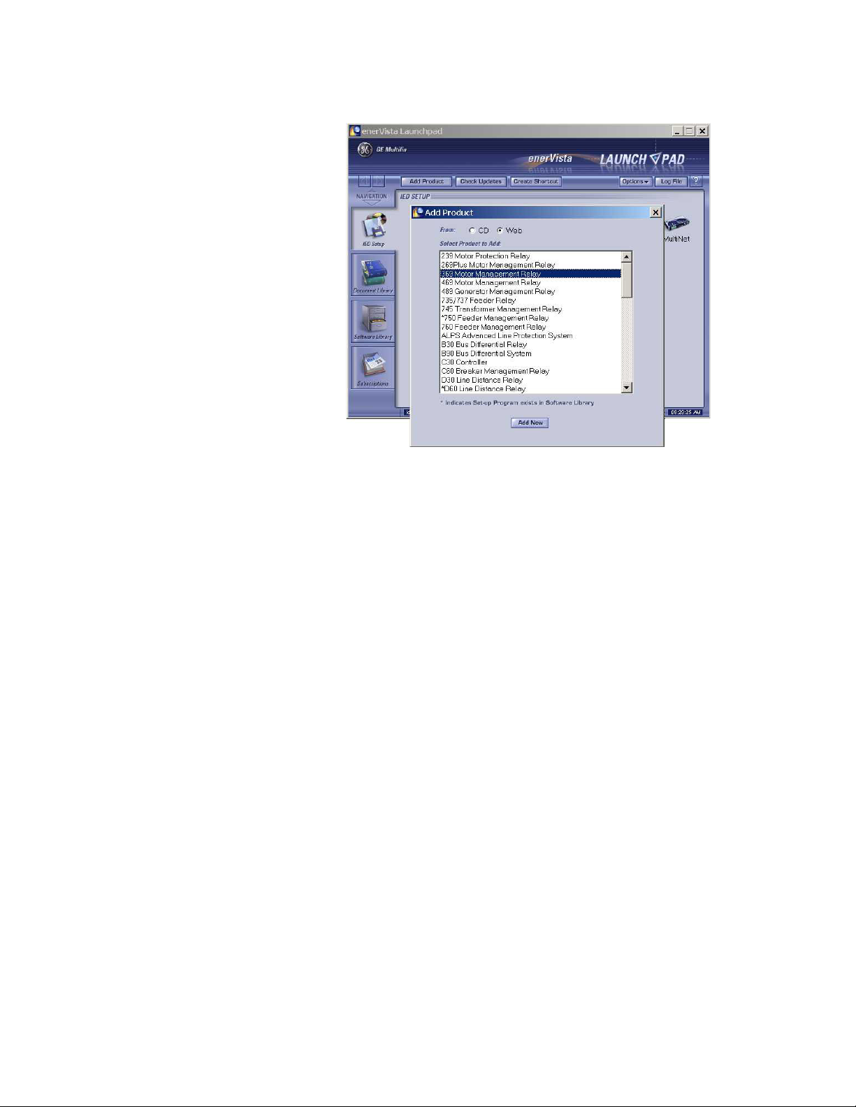
CHAPTER 4: USER INTERFACES ENERVISTA 369 SETUP INTERFACE
EnerVista Launchpad will obtain the installation program from the Web or CD.
Z Once the download is complete, double-click the installation
program to install the EnerVista 369 Setup software.
The program will request the user to create a backup 3.5" floppy-disk set.
Z If this is desired, click on the Start Copying button; otherwise, click
on the CONTINUE WITH 369 Relay INSTALLATION button.
Z Select the complete path, including the new directory name, where
the EnerVista 369 Setup software will be installed.
Z Click on Next to begin the installation.
The files will be installed in the directory indicated and the
installation program will automatically create icons and add
EnerVista 369 Setup software to the Windows start menu.
369 MOTOR MANAGEMENT RELAY– INSTRUCTION MANUAL 4–61

ENERVISTA 369 SETUP INTERFACE CHAPTER 4: USER INTERFACES
Z Click Finish to end the installation.
The 369 Relay device will be added to the list of installed IEDs in the
enerVista Launchpad window, as shown below.
4–62 369 MOTOR MANAGEMENT RELAY– INSTRUCTION MANUAL

CHAPTER 4: USER INTERFACES CONNECTING ENERVISTA 369 SETUP TO THE RELAY
4.3 Connecting EnerVista 369 Setup to the Relay
4.3.1 Configuring Serial Communications
Before starting, verify that the serial cable is properly connected to either the RS232 port
on the front panel of the device (for RS232 communications) or to the RS485 terminals on
the back of the device (for RS485 communications).
This example demonstrates an RS232 connection. For RS485 communications, the GE
Multilin F485 converter will be required. Refer to the F485 manual for additional details. To
configure the relay for Ethernet communications, see Configuring Ethernet
Communications on page 4–65.
Z Install and start the latest version of the EnerVista 369 Setup
software (available from the GE enerVista CD).
See the previous section for the installation procedure.
Z Click on the Device Setup button to open the Device Setup window.
Z Click the Add Site button to define a new site.
Z Enter the desired site name in the Site Name field.
If desired, a short description of site can also be entered along with
the display order of devices defined for the site. In this example, we
will use “Substation 1” as the site name.
Z Click the OK button when complete.
The new site will appear in the upper-left list in the EnerVista 369 Setup window.
Z Click the Add Device button to define the new device.
Z Enter the desired name in the Device Name field and a description
(optional) of the site.
Z Select “Serial” from the Interface drop-down list.
This will display a number of interface parameters that must be
entered for proper RS232 functionality.
369 MOTOR MANAGEMENT RELAY– INSTRUCTION MANUAL 4–63

CONNECTING ENERVISTA 369 SETUP TO THE RELAY CHAPTER 4: USER INTERFACES
Z Enter the slave address and COM port values (from the S1 369
RELAY SETUP
ÖØ 369 RELAY COMMUNICATIONS menu) in the
Slave Address and COM Port fields.
Z Enter the physical communications parameters (baud rate and
parity settings) in their respective fields.
Z Click the Read Order Code button to connect to the 369 Relay device
and upload the order code.
If an communications error occurs, ensure that the 369 Relay serial
communications values entered in the previous step correspond to
the relay setting values.
Z Click OK when the relay order code has been received.
The new device will be added to the Site List window (or Online
window) located in the top left corner of the main EnerVista 369
Setup window.
The 369 Relay Site Device has now been configured for serial communications. Proceed to
Connecting to the Relay on page 4–67 to begin communications.
4–64 369 MOTOR MANAGEMENT RELAY– INSTRUCTION MANUAL

CHAPTER 4: USER INTERFACES CONNECTING ENERVISTA 369 SETUP TO THE RELAY
4.3.2 Using the Quick Connect Feature
The Quick Connect button can be used to establish a fast connection through the front
panel RS232 port of a 369 Relay relay. The following window will appear when the Quick
Connect button is pressed:
As indicated by the window, the Quick Connect feature quickly connects the EnerVista 369
Setup software to a 369 Relay front port with the following settings: 9600 baud, no parity, 8
bits, 1 stop bit. Select the PC communications port connected to the relay and press the
Connect button.
The EnerVista 369 Setup software will display a window indicating the status of
communications with the relay. When connected, a new Site called “Quick Connect” will
appear in the Site List window. The properties of this new site cannot be changed.
The 369 Relay Site Device has now been configured via the Quick Connect feature for serial
communications. Proceed to Connecting to the Relay on page 4–67 to begin
communications.
4.3.3 Configuring Ethernet Communications
Before starting, verify that the Ethernet cable is properly connected to the MultiNET device,
and that the MultiNET has been configured and properly connected to the relay. Refer to
the MultiNET manual for additional details on configuring the MultiNET to work with the
369 Relay.
369 MOTOR MANAGEMENT RELAY– INSTRUCTION MANUAL 4–65

CONNECTING ENERVISTA 369 SETUP TO THE RELAY CHAPTER 4: USER INTERFACES
Z Install and start the latest version of the EnerVista 369 Setup
software (available from the GE enerVista CD).
See the previous section for the installation procedure.
Z Click on the Device Setup button to open the Device Setup window.
Z Click the Add Site button to define a new site.
Z Enter the desired site name in the Site Name field.
If desired, a short description of site can also be entered along with
the display order of devices defined for the site. In this example, we
will use “Substation 2” as the site name.
Z Click the OK button when complete.
The new site will appear in the upper-left list in the EnerVista 369 Setup window.
Z Click the Add Device button to define the new device.
Z Enter the desired name in the Device Name field and a description
(optional) of the site.
Z Select Ethernet from the Interface drop-down list.
This will display a number of interface parameters that must be
entered for proper Ethernet functionality.
Z Enter the IP address assigned to the MultiNET adapter.
Z Enter the slave address and Modbus port values (from the
RELAY SETUP
ÖØ 369 RELAY COMMUNICATIONS menu) in the
S1 369
Slave Address and Modbus Port fields.
4–66 369 MOTOR MANAGEMENT RELAY– INSTRUCTION MANUAL

CHAPTER 4: USER INTERFACES CONNECTING ENERVISTA 369 SETUP TO THE RELAY
Z Click the Read Order Code button to connect to the 369 Relay device
and upload the order code.
If an communications error occurs, ensure that the 369 Relay
Ethernet communications values entered in the previous step
correspond to the relay and MultiNET setting values.
Z Click OK when the relay order code has been received.
The new device will be added to the Site List window (or Online
window) located in the top left corner of the main EnerVista 369
Setup window.
The 369 Relay Site Device has now been configured for Ethernet communications. Proceed
to the following section to begin communications.
4.3.4 Connecting to the Relay
Now that the communications parameters have been properly configured, the user can
easily connect to the relay.
Z Expand the Site list by double clicking on the site name or clicking on
the «+» box to list the available devices for the given site (for
example, in the “Substation 1” site shown below).
Z Desired device trees can be expanded by clicking the «+» box. The
following list of headers is shown for each device:
• Device Definitions
• Settings
• Actual Values
• Commands
• Communications
369 MOTOR MANAGEMENT RELAY– INSTRUCTION MANUAL 4–67

CONNECTING ENERVISTA 369 SETUP TO THE RELAY CHAPTER 4: USER INTERFACES
Z Expand the Settings > Relay Setup list item and double click on Front
Panel to open the Front Panel settings window as shown below:
FIGURE 4–3: Main Window After Connection
The Front Panel settings window will open with a corresponding status indicator
on the lower left of the EnerVista 369 Setup window.
Z If the status indicator is red, verify that the serial or Ethernet cable is
properly connected to the relay, and that the relay has been properly
configured for communications (steps described earlier).
The Front Panel settings can now be edited, printed, or changed according to user
specifications. Other setpoint and commands windows can be displayed and edited in a
similar manner. Actual values windows are also available for display. These windows can
be locked, arranged, and resized at will.
Note
Refer to the EnerVista 369 Setup Help File for additional information about the using
the software.
4–68 369 MOTOR MANAGEMENT RELAY– INSTRUCTION MANUAL

CHAPTER 4: USER INTERFACES WORKING WITH SETPOINTS AND SETPOINT FILES
4.4 Working with Setpoints and Setpoint Files
4.4.1 Engaging a Device
The EnerVista 369 Setup software may be used in on-line mode (relay connected) to
directly communicate with a 369 Relay relay. Communicating relays are organized and
grouped by communication interfaces and into sites. Sites may contain any number of
relays selected from the SR or UR product series.
4.4.2 Entering Setpoints
The System Setup page will be used as an example to illustrate the entering of setpoints. In
this example, we will be changing the current sensing setpoints.
Z Establish communications with the relay.
Z Select the Setpoint > S2 System Setup > CT/VT Setup menu item.
This can be selected from the device setpoint tree or the main
window menu bar.
Z Select the
the parameter box.
This will display three arrows: two to increment/decrement the value
and another to launch the numerical calculator.
PHASE CT PRIMARY setpoint by clicking anywhere in
369 MOTOR MANAGEMENT RELAY– INSTRUCTION MANUAL 4–69
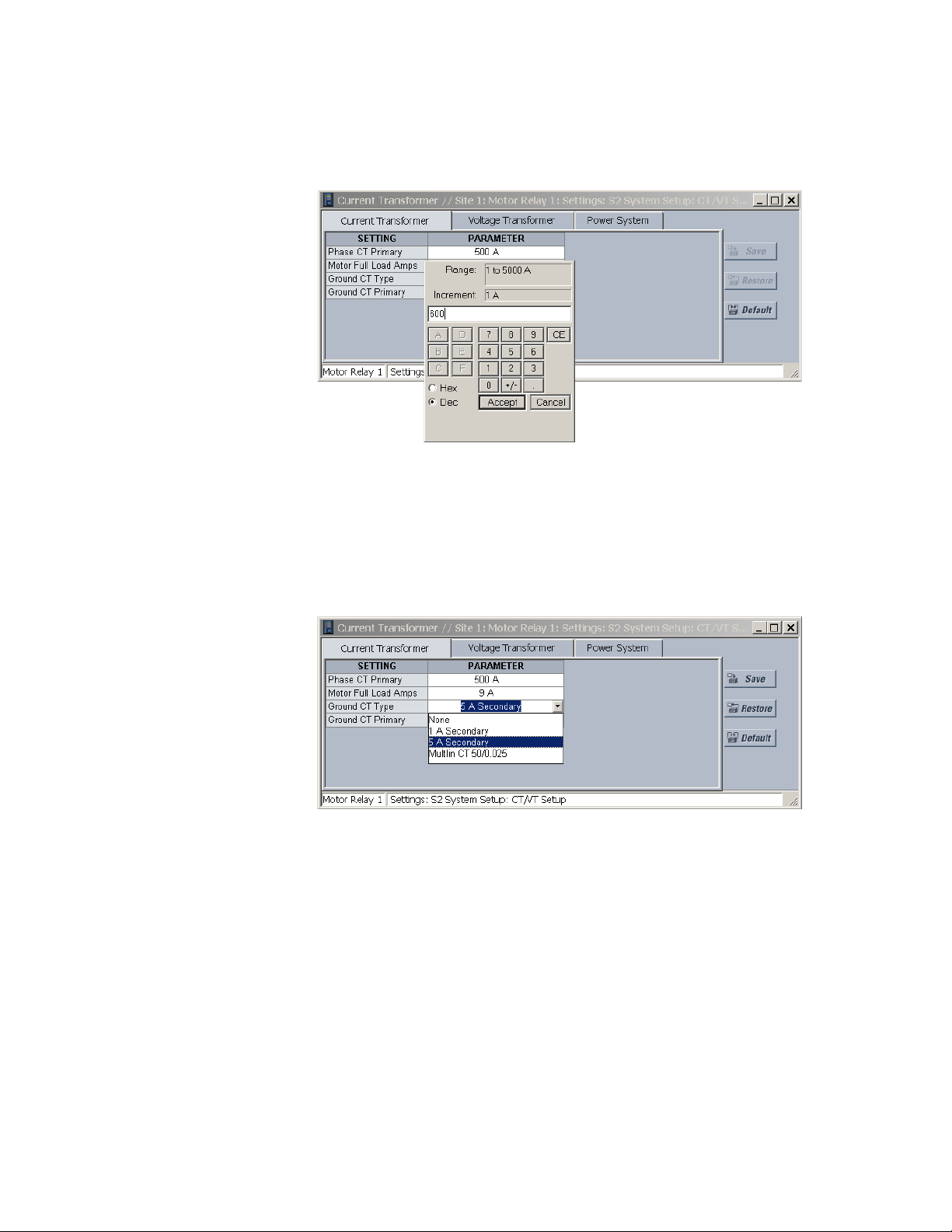
WORKING WITH SETPOINTS AND SETPOINT FILES CHAPTER 4: USER INTERFACES
Z Clicking the arrow at the end of the box displays a numerical keypad
interface that allows the user to enter a value within the setpoint
range displayed near the top of the keypad:
Z Click Accept to exit from the keypad and keep the new value.
Z Click on Cancel to exit from the keypad and retain the old value.
Z For setpoints requiring non-numerical pre-set values (e.g.
CT TYPE
above), clicking anywhere within the setpoint value box
GROUND
displays a drop-down selection menu arrow. Select the desired value
from this list.
Z For setpoints requiring an alphanumeric text string (e.g. message
scratchpad messages), the value may be entered directly within the
setpoint value box.
Z Click on Save to save the values into the 369 Relay.
Z Click OK to accept any changes and exit the window.
Z Otherwise, click Restore to retain previous values and exit.
4–70 369 MOTOR MANAGEMENT RELAY– INSTRUCTION MANUAL

CHAPTER 4: USER INTERFACES WORKING WITH SETPOINTS AND SETPOINT FILES
4.4.3 File Support
Opening any EnerVista 369 Setup file will automatically launch the application or provide
focus to the already opened application. If the file is a settings file (has a ‘369 Relay’
extension) which had been removed from the Settings List tree menu, it will be added back
to the Settings List tree.
New files will be automatically added to the tree, which is sorted alphabetically with
respect to settings file names.
4.4.4 Using Setpoints Files
Overview
The EnerVista 369 Setup software interface supports three ways of handling changes to
relay settings:
•In off-line mode (relay disconnected) to create or edit relay settings files for later
download to communicating relays.
• Directly modifying relay settings while connected to a communicating relay, then
saving the settings when complete.
• Creating/editing settings files while connected to a communicating relay, then
saving them to the relay when complete.
Settings files are organized on the basis of file names assigned by the user. A settings file
contains data pertaining to the following categories of relay settings:
• Device Definition
•Product Setup
•System Setup
• Grouped Elements
• Control Elements
• Inputs/Outputs
•Testing
Factory default values are supplied and can be restored after any changes.
The EnerVista 369 Setup software displays relay setpoints with the same hierarchy as the
front panel display. For specific details on setpoints, refer to Chapter 5.
Downloading and Saving Setpoints Files
Setpoints must be saved to a file on the local PC before performing any firmware
upgrades. Saving setpoints is also highly recommended before making any setpoint
changes or creating new setpoint files.
The EnerVista 369 Setup window, setpoint files are accessed in the Settings List control bar
window or the Files Window. Use the following procedure to download and save setpoint
files to a local PC.
Z Ensure that the site and corresponding device(s) have been properly
defined and configured as shown in Connecting EnerVista 369 Setup
to the Relay on page 4–63.
369 MOTOR MANAGEMENT RELAY– INSTRUCTION MANUAL 4–71

WORKING WITH SETPOINTS AND SETPOINT FILES CHAPTER 4: USER INTERFACES
Z Select the desired device from the site list.
Z Select the File > Read Settings from Device menu item to obtain
settings information from the device.
After a few seconds of data retrieval, the software will request the name and
destination path of the setpoint file. The corresponding file extension will be
automatically assigned.
Z Press Save to complete the process.
A new entry will be added to the tree, in the File pane, showing path
and file name for the setpoint file.
Adding Setpoints Files to the Environment
The EnerVista 369 Setup software provides the capability to review and manage a large
group of setpoint files. Use the following procedure to add a new or existing file to the list.
Z In the files pane, right-click on ‘Files’.
Z Select the Add Existing Setting File item as shown
:
The Open dialog box will appear, prompting the user to select a previously saved
setpoint file.
Z As for any other Microsoft Windows
®
application, browse for the file
to be added then
Z Click Open.
The new file and complete path will be added to the file list.
4–72 369 MOTOR MANAGEMENT RELAY– INSTRUCTION MANUAL

CHAPTER 4: USER INTERFACES WORKING WITH SETPOINTS AND SETPOINT FILES
Creating a New Settings File using Motor Settings Auto-Config
The EnerVista 369 Setup software allows the user to create new Settings files independent
of a connected device. These can be uploaded to a relay at a later date.
One method of doing this - the EnerVista Motor Settings Auto-Config option - allows the
user to easily create new Settings Files automatically, using a guided step-by-step process
as outlined below.
Note
The Motor Settings Auto-Config option does NOT allow the user to configure existing
Settings Files.
The following procedure illustrates how to create new Settings Files using the Motor
Settings Auto-Config option:
Z At the top of the screen, click on the Motor Settings Auto-Config
button.
OR
Z On the main menu, select File > Motor Settings Auto-Configurator
The EnerVista 369 Setup software displays the following box, allowing the
configuration of the Settings File as shown.
369 MOTOR MANAGEMENT RELAY– INSTRUCTION MANUAL 4–73

WORKING WITH SETPOINTS AND SETPOINT FILES CHAPTER 4: USER INTERFACES
.
Note
It is important to define the correct firmware version to ensure that settings not available
in a particular version are not downloaded into the relay
Z Select the Firmware Version for the new Settings File.
Z For future reference, enter some useful information in the
Description box to facilitate the identification of the device and the
purpose of the file.
Z To select a file name and path for the new file, click the button [...]
beside the File Name box.
Z Select the file name and path to store the file, or select any displayed
file name to update an existing file.
All 369 Relay Settings Files should have the extension ‘369 Relay’ (for
example, ‘motor1.369 Relay’).
4–74 369 MOTOR MANAGEMENT RELAY– INSTRUCTION MANUAL

CHAPTER 4: USER INTERFACES WORKING WITH SETPOINTS AND SETPOINT FILES
Z Click Next and OK to continue the process.
A new window - Step 1 - will appear:
Z Fill in the fields as indicated.
Z When complete, press Next .
The next window - Step 2 - will appear as follows:
Note
As each Step is completed, the user will be prompted to make appropriate changes to
what has been entered, if the Auto-Configurator determines that the parameter
entered is incorrect or inappropriate for the situation.
369 MOTOR MANAGEMENT RELAY– INSTRUCTION MANUAL 4–75

WORKING WITH SETPOINTS AND SETPOINT FILES CHAPTER 4: USER INTERFACES
Z Continue filling in the fields as indicated.
Once you have completed all 6 Steps, the final window will show as follows:
Z Click Finish to complete the Auto-Config procedure.
The Motor Settings Auto-Configurator window will disappear.
4–76 369 MOTOR MANAGEMENT RELAY– INSTRUCTION MANUAL

CHAPTER 4: USER INTERFACES WORKING WITH SETPOINTS AND SETPOINT FILES
A new Settings File containing the parameters you have just input will appear in
the Files pane as shown:
Creating a New Settings File without using Motor Settings Auto-Config
The EnerVista 369 Setup software allows the user to create new Settings files independent
of a connected device. These can be uploaded to a relay at a later date. The following
manual procedure - as distinct from the Motor Settings Auto-Config option described
above - illustrates how to create new Settings Files.
Z In the File pane, right click on File.
Z Select the New Settings File item.
The EnerVista 369 Setup software displays the following window,
allowing the configuration of the Settings File as shown below.
Note
Note that this window allows you to choose between creating your Settings File
manually or using the Motor Settings Auto-Configurator as detailed above.
369 MOTOR MANAGEMENT RELAY– INSTRUCTION MANUAL 4–77

WORKING WITH SETPOINTS AND SETPOINT FILES CHAPTER 4: USER INTERFACES
Note
It is important to define the correct firmware version to ensure that settings not available
in a particular version are not downloaded into the relay
Z Select the Firmware Version for the new Settings File.
Z For future reference, enter some useful information in the
Description box to facilitate the identification of the device and the
purpose of the file.
Z To select a file name and path for the new file, click the button
beside the File Name box [...].
Z Select the file name and path to store the file, or select any displayed
file name to update an existing file.
All 369 Relay Settings Files should have the extension ‘369 Relay’ (for
example, ‘motor1.369 Relay’).
Z Click the appropriate radio button (yes or no) to choose between
Auto-Configurator or manual creation of the Settings File.
Z Click OK to complete the process.
Once this step is completed, the new file, with a complete path, will
be added to the EnerVista 369 Setup software environment.
4–78 369 MOTOR MANAGEMENT RELAY– INSTRUCTION MANUAL

CHAPTER 4: USER INTERFACES WORKING WITH SETPOINTS AND SETPOINT FILES
Z Enter the appropriate settings manually to complete the new
Settings File.
Creating a New Setpoint File
The EnerVista 369 Setup software allows the user to create new setpoint files independent
of a connected device. These can be uploaded to a relay at a later date. The following
procedure illustrates how to create new setpoint files.
Z In the File pane, right click on File.
Z Select the New Settings File item.
The EnerVista 369 Setup software displays the following box will
appear, allowing the configuration of the setpoint file for the correct
firmware version. It is important to define the correct firmware
version to ensure that setpoints not available in a particular version
are not downloaded into the relay.
369 MOTOR MANAGEMENT RELAY– INSTRUCTION MANUAL 4–79

WORKING WITH SETPOINTS AND SETPOINT FILES CHAPTER 4: USER INTERFACES
Z Select the firmware version.
Z For future reference, enter some useful information in the
Description box to facilitate the identification of the device and the
purpose of the file.
Z Enter any installed options (metering/backspin and Profibus), as well
as the slave addresses of any remote RTDs.
Note that the RRTD units must be connected in order from 1 to 4. If
only one RRTD is used, it's slave address must be programmed under
RRTD1 Slave Address. The next RRTD to be connected would be set
up under RRTD2 Slave Address, and so forth.
Z To select a file name and path for the new file, click the button
beside the Enter File Name box.
Z Select the file name and path to store the file, or select any displayed
file name to update an existing file.
All 369 Relay setpoint files should have the extension ‘369 Relay’ (for
example, ‘motor1.369 Relay’).
Z Click Save and OK to complete the process.
Once this step is completed, the new file, with a complete path, will
be added to the EnerVista 369 Setup software environment.
Upgrading Setpoint Files to a New Revision
It is often necessary to upgrade the revision code for a previously saved setpoint file after
the 369 Relay firmware has been upgraded (for example, this is required for firmware
upgrades). This is illustrated in the following procedure.
Z Establish communications with the 369 Relay.
Z Select the Actual > A5 Product Info menu item and record the
Software Revision identifier of the relay firmware.
4–80 369 MOTOR MANAGEMENT RELAY– INSTRUCTION MANUAL

CHAPTER 4: USER INTERFACES WORKING WITH SETPOINTS AND SETPOINT FILES
Z Load the setpoint file to be upgraded into the EnerVista 369 Setup
environment as described in Adding Setpoints Files to the
Environment on page 4–72.
Z In the File pane, select the saved setpoint file.
Z From the main window menu bar, select the File > Properties menu
item.
Z Note the File Version of the setpoint file.
If this version (e.g. 5.00 shown below) is different from the Software
Revision code noted in step 2, select a New File Version that
matches the Software Revision code from the pull-down menu.
For example, if the firmware revision is 27I600A4.000 (software revision 6.00) and
the current setpoint file revision is 5.00, change the setpoint file revision to “6.0X”.
Z When complete, click Convert to convert the setpoint file to the
desired revision.
A dialog box will request confirmation. See Loading Setpoints from a
File on page 4–82 for instructions on loading this setpoint file into the
369 Relay.
Printing Setpoints and Actual Values
The EnerVista 369 Setup software allows the user to print partial or complete lists of
setpoints and actual values. Use the following procedure to print a list of setpoints:
Z Select a previously saved setpoints file in the File pane or establish
communications with a 369 Relay device.
Z From the main window, select the File > Print Settings menu item.
The Print/Export Options dialog box will appear.
Z Select Settings in the upper section.
369 MOTOR MANAGEMENT RELAY– INSTRUCTION MANUAL 4–81

WORKING WITH SETPOINTS AND SETPOINT FILES CHAPTER 4: USER INTERFACES
Z Select either Include All Features (for a complete list) or Include Only
Enabled Features (for a list of only those features which are
currently used) in the filtering section.
Z Click OK.
The process for File > Print Preview Settings is identical to the steps above.
Setpoints lists can be printed in the same manner by right clicking on the desired file (in the
file list) or device (in the device list) and selecting the Print Device Information or Print
Settings File options.
A complete list of actual values can also be printed from a connected device with the
following procedure:
Z Establish communications with the desired 369 Relay device.
Z From the main window, select the File > Print Settings menu item.
The Print/Export Options dialog box will appear.
Z Select Actual Values in the upper section.
Z Select either Include All Features (for a complete list) or Include Only
Enabled Features (for a list of only those features which are
currently used) in the filtering section.
Z Click OK.
Z Actual values lists can be printed in the same manner by right
clicking on the desired device (in the device list) and selecting the
Print Device Information option.
Loading Setpoints from a File
Note
An error message will occur when attempting to download a setpoint file with a
revision number that does not match the relay firmware. If the firmware has been
upgraded since saving the setpoint file, see Upgrading Setpoint Files to a New Revision
on page 4–80 for instructions on changing the revision number of a setpoint file.
The following procedure illustrates how to load setpoints from a file. Before loading a
setpoints file, it must first be added to the EnerVista 369 Setup environment as described
in Adding Setpoints Files to the Environment on page 4–72.
4–82 369 MOTOR MANAGEMENT RELAY– INSTRUCTION MANUAL

CHAPTER 4: USER INTERFACES WORKING WITH SETPOINTS AND SETPOINT FILES
Z Select the previously saved setpoints file from the File pane of the
EnerVista 369 Setup software main window.
Z Select the File > Properties menu item and verify that the
corresponding file is fully compatible with the hardware and
firmware version of the target relay.
If the versions are not identical, see Upgrading Setpoint Files to a
New Revision on page 4–80 for details on changing the setpoints file
version.
Z Right-click on the selected file.
Z Select the Write Settings to Device item.
Z Select the target relay from the list of devices shown.
Z Click Send.
If there is an incompatibility, an error will occur: If there are no
incompatibilities between the target device and the settings file, the
data will be transferred to the relay. An indication of the percentage
completed will be shown in the bottom of the main window.
369 MOTOR MANAGEMENT RELAY– INSTRUCTION MANUAL 4–83

UPGRADING RELAY FIRMWARE CHAPTER 4: USER INTERFACES
4.5 Upgrading Relay Firmware
4.5.1 Description
To upgrade the 369 Relay firmware, follow the procedures listed in this section. Upon
successful completion of this procedure, the 369 Relay will have new firmware installed
with the original setpoints.
The latest firmware files are available from the GE Multilin website at http://
www.GEindustrial.com/multilin.
4.5.2 Saving Setpoints to a File
Before upgrading firmware, it is very important to save the current 369 Relay settings to a
file on your PC. After the firmware has been upgraded, it will be necessary to load this file
back into the 369 Relay.
Refer to Downloading and Saving Setpoints Files on page 4–71 for details on saving relay
setpoints to a file.
4.5.3 Loading New Firmware
Loading new firmware into the 369 Relay flash memory is accomplished as follows:
The EnerVista 369 Setup software will request the new firmware file.
Z Connect the relay to the local PC and save the setpoints to a file as
shown in Downloading and Saving Setpoints Files on page 4–71.
Z Select the Communications > Update Firmware menu item.
The following warning message will appear: Select Yes to proceed or
No the cancel the process.
Z Do NOT proceed unless you have saved the current setpoints.
4–84 369 MOTOR MANAGEMENT RELAY– INSTRUCTION MANUAL

CHAPTER 4: USER INTERFACES UPGRADING RELAY FIRMWARE
53 CMC 320 . 000
Modification Number (000 = None)
Firmware Version (320 = 3.20)
Internal Identifier
Product Code (53 = 369)
Z Locate the firmware file to load into the 369 Relay.
The firmware filename has the following format:
The EnerVista 369 Setup software automatically lists all filenames beginning with
‘53’.
Z Select the appropriate file.
Z Click OK to continue.
The software will prompt with another Upload Firmware Warning window. This will
be the final chance to cancel the firmware upgrade before the flash memory is
erased.
Z Click Yes to continue or No to cancel the upgrade.
The EnerVista 369 Setup software now prepares the 369 Relay to receive the new
firmware file. The 369 Relay will display a message indicating that it is in Upload
Mode. While the file is being loaded into the 369 Relay, a status box appears
indicating how much of the new firmware file has been transferred and how much
is remaining, as well as the upgrade status. The entire transfer process takes
approximately five minutes.
The EnerVista 369 Setup software will notify the user when the 369 Relay has
finished loading the file.
Z Carefully read any displayed messages.
Z Click OK to return the main screen.
Note
Cycling power to the relay is highly recommended after a firmware upgrade.
After successfully updating the 369 Relay firmware, the relay will not be in service and will
require setpoint programming. To communicate with the relay, the following settings will
have to be manually programmed.
SLAVE ADDRESS
BAUD RATE
PARITY
(if applicable)
369 MOTOR MANAGEMENT RELAY– INSTRUCTION MANUAL 4–85
When communications is established, the saved setpoints must be reloaded back into the
relay. See Loading Setpoints from a File on page 4–82 for details.
Modbus addresses assigned to firmware modules, features, settings, and corresponding
data items (i.e. default values, min/max values, data type, and item size) may change
slightly from version to version of firmware.

UPGRADING RELAY FIRMWARE CHAPTER 4: USER INTERFACES
The addresses are rearranged when new features are added or existing features are
enhanced or modified. The
EEPROM DATA ERROR message displayed after upgrading/
downgrading the firmware is a resettable, self-test message intended to inform users that
the Modbus addresses have changed with the upgraded firmware. This message does not
signal any problems when appearing after firmware upgrades.
4–86 369 MOTOR MANAGEMENT RELAY– INSTRUCTION MANUAL

CHAPTER 4: USER INTERFACES ADVANCED ENERVISTA 369 SETUP FEATURES
4.6 Advanced EnerVista 369 Setup Features
4.6.1 Triggered Events
While the interface is in either on-line or off-line mode, data generated by triggered
specified parameters can be viewed and analyzed via one of the following features:
• Event Recorder: The event recorder captures contextual data associated with the
last 512 events, listed in chronological order from most recent to the oldest.
• Oscillography: The oscillography waveform traces and digital states provide a
visual display of power system and relay operation data captured during specific
triggered events.
4.6.2 Trending
Trending from the 369 Relay is accomplished via EnerVista 369 Setup. Many different
parameters can be trended and graphed at sampling periods from 1 second up to 1 hour.
The parameters which can be trended by EnerVista 369 Setup are:
• Currents/Voltages: phase currents A/B/C; average phase current; motor load;
current unbalance; ground current; and voltages Vab, Vbc, Vca Van, Vbn and Vcn
• Power: power factor; real power (kW); reactive power (kvar); Apparent Power (kVA);
positive watthours; positive varhours; and negative varhours
• Temperature: Hottest Stator RTD; RTDs 1 through 12; and RRTDs 1 through 12
• Other: thermal capacity used and system frequency
Z To use the Trending function, run the EnerVista 369 Setup software
and establish communications with a connected 369 Relay unit.
Z Select the Actual > Trending menu item to open the Trending
window.
369 MOTOR MANAGEMENT RELAY– INSTRUCTION MANUAL 4–87

ADVANCED ENERVISTA 369 SETUP FEATURES CHAPTER 4: USER INTERFACES
FIGURE 4–4: Trending View
Z Program the parameters to display by selecting them from the pull
down menus.
Z Select the Sample Rate.
Z Select RUN to begin the trending sampling.
The trended values can be printed using Print Trending Graph
button.
The Trending File Setup button can be used to write the graph data
to a file in a standard spreadsheet format.
Z Ensure that the Write Trended Data to File box is checked, and that
the Sample Rate is at a minimum of 5 seconds.
Z Set the file capacity limit to the amount of memory available for
trended data.
4–88 369 MOTOR MANAGEMENT RELAY– INSTRUCTION MANUAL

CHAPTER 4: USER INTERFACES ADVANCED ENERVISTA 369 SETUP FEATURES
4.6.3 Waveform Capture (Trace Memory)
The EnerVista 369 Setup software can be used to capture waveforms (or view trace
memory) from the 369 Relay relay at the instance of a trip. A maximum of 16 cycles can be
captured and the trigger point can be adjusted to anywhere within the set cycles. The last
three waveform events are viewable.
The following waveforms can be captured:
•Phase A, B, and C currents (I
• Ground and current (I
• Phase A-N, B-N, and C-N voltages (V
Phase A-B and C-B (V
ab
• Digital data for output relays and contact input states.
Z With the EnerVista 369 Setup software running and communications
established, select the Actual > Waveform Capture menu item to
open the waveform capture setup window:
, Ib, and Ic)
a
)
g
, Vbn, and Vcn) if wye-connected
an
and Vcb) if open-delta connected
Z Click on Trigger Waveform to trigger a waveform capture.
The waveform file numbering starts with the number zero in the 369
Relay; therefore, the maximum trigger number will always be one
less then the total number triggers available.
Z Click on the Save to File button to save the selected waveform to the
local PC.
A new window will appear requesting for file name and path.
The file is saved as a COMTRADE File, with the extension ‘CFG’. In addition to the
COMTRADE file, two other files are saved. One is a CSV (comma delimited values)
file, which can be viewed and manipulated with compatible third-party software.
The other file is a DAT File, required by the COMTRADE file for proper display of
waveforms.
Z To view a previously saved COMTRADE File, click the Open button.
Z Select the corresponding COMTRADE File.
369 MOTOR MANAGEMENT RELAY– INSTRUCTION MANUAL 4–89

ADVANCED ENERVISTA 369 SETUP FEATURES CHAPTER 4: USER INTERFACES
Z To view the captured waveforms, click the Launch Viewer button.
A detailed Waveform Capture window will appear as shown below:
FIGURE 4–5: Waveform Capture Window Attributes
The red vertical line indicates the trigger point of the relay.
The date and time of the trip is displayed at the top left corner of the window. To
match the captured waveform with the event that triggered it, make note of the
time and date shown in the graph. Then, find the event that matches the same
time and date in the event recorder. The event record will provide additional
information on the cause and the system conditions at the time of the event.
Additional information on how to download and save events is shown in Event
Recorder on page 4–99.
4–90 369 MOTOR MANAGEMENT RELAY– INSTRUCTION MANUAL

CHAPTER 4: USER INTERFACES ADVANCED ENERVISTA 369 SETUP FEATURES
4.6.4 Motor Start Data Logger
In addition to the learned information captured for every start, the Motor Start Data
Logger will record up to 30 seconds of digital and analog waveforms during motor starts.
Captured information includes:
• Individual and average phase current
• Current unbalance
• Ground current
• Individual and average phase voltages
• Thermal capacity used
• System frequency
• Breaker status contact
• Motor speed (low/high)
4.6.5 Data Logger
The user-configurable Data Logger allows users to trend information to help configure
protection setpoints, as well as to schedule preventative maintenance. The Data Logger:
• allows trending of up to 16 analog or digital parameters at a time
• allows trending of any metered or calculated analog value within a provided list
• allows trending of digital input and output states
• stores all trended information in the relay’s volatile memory (RAM)
• allows user-configurable resolution of trending from 1 second to 1 hour (3600s)
• allows up to 50 Logs to be created
• is available only with the Enhanced “E” option.
4.6.5.1Support in Enervista PC Software
Enervista PC Program supports the Data Logger on two screens on the Online Device
tree:
1. Setpoints: Settings > S1 Setup > Data Logger
2. Actual Values: Actual Values > A1 Motor Status > Data Logger
369 MOTOR MANAGEMENT RELAY– INSTRUCTION MANUAL 4–91

ADVANCED ENERVISTA 369 SETUP FEATURES CHAPTER 4: USER INTERFACES
4.6.5.2Setpoints
Users can configure the Data Logger Settings from Settings > S1 Setup > Data Logger
A typical Data Logger Settings screen is as follows:
The Settings in the Data Logger screen are:
Log Interval : The user can configure the Data Logger interval 1 sec to 3600 sec
Recording Type : The user can select from the two available methods of logging.
Run to Fill: Allows logging of Channel data until the memory is full, then stops.
Circulate: Allows continuous logging of Channel data .
4–92 369 MOTOR MANAGEMENT RELAY– INSTRUCTION MANUAL

CHAPTER 4: USER INTERFACES ADVANCED ENERVISTA 369 SETUP FEATURES
4.6.5.3Channel 1 to 16 Assignment
Users can configure 16 channels from the available 102 inputs (97 Analog inputs and 5
Digital Inputs/Outputs) from the screen.
The following is the list of Inputs which can be assigned to any of the 16 Channels:
Motor Thermal
1
Capacity Used
Digital Input and
2
Output Relays Status
35
36
3 Phase A Current 37
4 Phase B Current 38
5 Phase C Current 39
Average Phase
6
Current
40
7 Motor Load 41
8 Current Unbalance 42
Unbalanced Biased
9
Motor Load
43 Current Demand 77
Local RTD #5
Temperature
Local RTD #6
Temperature
Local RTD #7
Temperature
Local RTD #8
Temperature
Local RTD #9
Temperature
Local RTD #10
Temperature
Local RTD #11
Temperature
Local RTD #12
Temperature
69
70
71
72
73
74
75
76
10 Ground Current 44 Real Power Demand 78
11 Vab 45
12 Vbc 46
Reactive Power
Demand
Apparent Power
Demand
79
80
13 Vca 47 Peak Current Demand 81
14 Average Line Voltage 48
15 Van 49
16 Vbn 50
17 Vcn 51
Average Phase
18
Voltage
52
19 System Frequency 53
20 Power Factor 54
21 Real Power (kW) 55
22 Real Power (hp) 56
23 Reactive Power 57
Peak Real Power
Demand
Peak Reactive Power
Demand
Peak Apparent Power
Demand
RRTD 1 - RTD #1
Temperature
RRTD 1 - RTD #2
Temperature
RRTD 1 - RTD #3
Temperature
RRTD 1 - RTD #4
Temperature
RRTD 1 - RTD #5
Temperature
RRTD 1 - RTD #6
Temperature
RRTD 1 - RTD #7
Temperature
82
83
84
85
86
87
88
89
90
91
RRTD 2 - RTD #7
Temperature
RRTD 2 - RTD #8
Temperature
RRTD 2 - RTD #9
Temperature
RRTD 2 - RTD #10
Temperature
RRTD 2 - RTD #11
Temperature
RRTD 2 - RTD #12
Temperature
RRTD 3 - RTD #1
Temperature
RRTD 3 - RTD #2
Temperature
RRTD 3 - RTD #3
Temperature
RRTD 3 - RTD #4
Temperature
RRTD 3 - RTD #5
Temperature
RRTD 3 - RTD #6
Temperature
RRTD 3 - RTD #7
Temperature
RRTD 3 - RTD #8
Temperature
RRTD 3 - RTD #9
Temperature
RRTD 3 - RTD #10
Temperature
RRTD 3 - RTD #11
Temperature
RRTD 3 - RTD #12
Temperature
RRTD 4 - RTD #1
Temperature
RRTD 4 - RTD #2
Temperature
RRTD 4 - RTD #3
Temperature
RRTD 4 - RTD #4
Temperature
RRTD 4 - RTD #5
Temperature
369 MOTOR MANAGEMENT RELAY– INSTRUCTION MANUAL 4–93

ADVANCED ENERVISTA 369 SETUP FEATURES CHAPTER 4: USER INTERFACES
24 Apparent Power 58
Positive
25
MegaWatthours
59
26 Positive Megavarhours 60
Negative
27
Megavarhours
61
28 Positive KiloWatthours 62
29 Positive Kilovarhours 63
30 Negative Kilovarhours 64
Local RTD #1
31
32
33
34
Temperature
Local RTD #2
Temperature
Local RTD #3
Temperature
Local RTD #4
Temperature
65
66
67
68
RRTD 1 - RTD #8
Temperature
RRTD 1 - RTD #9
Temperature
RRTD 1 - RTD #10
Temperature
RRTD 1 - RTD #11
Temperature
RRTD 1 - RTD #12
Temperature
RRTD 2 - RTD #1
Temperature
RRTD 2 - RTD #2
Temperature
RRTD 2 - RTD #3
Temperature
RRTD 2 - RTD #4
Temperature
RRTD 2 - RTD #5
Temperature
RRTD 2 - RTD #6
Temperature
92
93
94
95
96
97
98
99
100
101
102
RRTD 4 - RTD #6
Temperature
RRTD 4 - RTD #7
Temperature
RRTD 4 - RTD #8
Temperature
RRTD 4 - RTD #9
Temperature
RRTD 4 - RTD #10
Temperature
RRTD 4 - RTD #11
Temperature
RRTD 4 - RTD #12
Temperature
RRTD 1 – Digital Input
and Output Relays
Status
RRTD 2 – Digital Input
and Output Relays
Status
RRTD 3 Digital Input
and Output Relays
Status
RRTD 4 Digital Input
and Output Relays
Status
4.6.5.4Actual Values
Actual Values > A1 Motor Status > Data Logger
This screen can be used to monitor the Datalog status , View and Save the Datalog, as well
as perform the Start/Stop operation on the Data Logger.
4–94 369 MOTOR MANAGEMENT RELAY– INSTRUCTION MANUAL
 Loading...