

GE 40795 Installation Manual
To change the faceplate
This step is optional. Before installation, you may want
to change the color of the faceplate to match your
wallplate or décor (white and light almond included).
1. Insert a small, flat-blade screw driver into
the grooves found on each side of the
front housing and pop up front plate.
2. Clip new faceplate into place.
3.
MTS5405
40795 v1
07/30/18
In-Wall Wi-Fi
Smart Outlet
Tomacorriente de
pared inteligente
con wifi
Es
Este dispositivo cumple con las Especificaciones del apartado 15 de las normas de la FCC y con las
especificaciones de las normas radioeléctricas (RSS) del Ministerio de Industria de Canadá aplicables
a aparatos exentos de licencia. El funcionamiento está sujeto a las siguientes dos condiciones:
(1) este dispositivo no debe provocar interferencia perjudicial, y (2) este dispositivo debe aceptar
toda interferencia que reciba, incluso la que pudiera causar un funcionamiento no deseado.
NOTA DE LA FCC: El fabricante no se hace responsable de ninguna interferencia de radio
o TV ocasionada por modificaciones no autorizadas efectuadas a este equipo. Dichas
modificaciones podrían anular la autoridad del usuario para utilizar el equipo.
NOTA : Este equipo ha sido probado y cumple con los límites para aparatos digitales de Clase B,
de conformidad con el apartado 15 de las normas de la FCC. Estos límites están diseñados para
proveer protección razonable contra interferencias perjudiciales en una instalación residencial. Este
equipo genera, usa y puede irradiar energía de radiofrecuencias y, si no se instala y usa según las
instrucciones, puede provocar interferencia perjudicial a las radiocomunicaciones. No obstante, no
hay garantías de que no ocurrirá interferencia en una instalación en particular. Si este equipo provoca
interferencia perjudicial a la recepción de radio o televisión, lo que puede determinarse encendiendo y
apagando el equipo, se recomienda que el usuario intente corregir la
interferencia por medio de la implementación de una o más de las siguientes medidas:
— Reorientar o reubicar la antena receptora.
— Incrementar la separación entre el equipo y el receptor.
— Conectar el equipo a un tomacorriente de un circuito diferente
del circuito al que está conectado el receptor.
— Consultar al distribuidor o a un técnico con experiencia en radio/televisión para
solicitar asistencia.
Nota importante: Para cumplir con los requisitos de cumplimiento de exposición de
radiofrecuencia de la FCC, no se permiten cambios a la antena o el dispositivo. Cualquier
cambio a la antena o dispositivo podría hacer que el dispositivo supere los requerimientos de
exposición de radiofrecuencia y anular la autoridad del usuario para operar el dispositivo.
En
This device complies with Part 15 of the FCC and Industry Canada license-exempt RSS standards.
Operation is subject to the following two conditions:
(1) this device may not cause harmful interference, and (2) this device must accept any
interference received, including interference that may cause undesired operation.
FCC NOTE: The manufacturer is not responsible for any radio or TV interference
caused by unauthorized modifications to this equipment. Such modifications
could void the user’s authority to operate the equipment.
NOTE: This equipment has been tested and found to comply with the limits for a Class B digital device,
pursuant to Part 15 of the FCC Rules. These limits are designed to provide reasonable protection
against harmful interference in a residential installation. This equipment generates, uses and can
radiate radio frequency energy, and if not installed and used in accordance with the instructions, may
cause harmful interference to radio communications. However, there is no guarantee interference
will not occur in a particular installation. If this equipment does cause harmful interference to
radio or television reception, which can be determined by turning the equipment off and on, the
user is encouraged to try to correct the interference by one or more of the following measures:
— Reorient or relocate the receiving antenna.
— Increase the separation between the equipment and receiver.
— Connect the equipment into an outlet on a circuit different from which the receiver is connected.
— Consult the dealer or an experienced radio/TV technician for help.
Important note: To comply with the FCC RF exposure compliance requirements, no change to the
antenna or the device is permitted. Any change to the antenna or the device could result in the
device exceeding the RF exposure requirements and void user’s authority to operate the device.
FCC / IC
RIESGO DE INCENDIO
RIESGO DE DESCARGA ELÉCTRICA
RIESGO DE QUEMADURAS
• NO SUPERE LOS VALORES NOMINALES ELÉCTRICOS
• NO UTILICE PARA CONTROLAR CALENTADORES
ELÉCTRICOS NI NINGÚN OTRO APARATO
ELÉCTRICO QUE PUEDA PRESENTAR UNA
SITUACIÓN PELIGROSA DEBIDO A UNA
ACTIVACIÓN AUTOMÁTICA SIN VIGILANCIA O
NO INTENCIONADA DEL CONTROLADOR.
• SE PROHÍBE SU EMPLEO EN EQUIPO MÉDICO
O EQUIPO PARA EL MANTENIMIENTO
DE LAS FUNCIONES VITALES
• USE SOLAMENTE EN INTERIORES
RISK OF FIRE
RISK OF ELECTRICAL SHOCK
RISK OF BURNS
• DO NOT EXCEED RATINGS
• DO NOT USE TO CONTROL ELECTRIC HEATERS
OR ANY OTHER APPLIANCES WHICH MAY
PRESENT A HAZARDOUS CONDITION DUE
TO UNATTENDED OR UNINTENTIONAL
OR AUTOMATIC POWER ON CONTROL.
• NOT FOR USE WITH MEDICAL OR
LIFE-SUPPORT EQUIPMENT
• FOR INDOOR USE ONLY
WARNING ADVERTENCIA
A. Line (Hot)
B. Neutral
C. Ground
D. Always-on outlet
E. Manual/program button
F. W i-Fi controlled outlet
Getting to know your new Wi-Fi Smart Outlet
• One Wi-Fi controlled outlet
• One always-ON outlet
• Remote ON/OFF control via the myTouchSmart app
• Manual ON/OFF override button on outlet
• This GE-branded device has advanced features that allow you to customize your
experience. These features can be adjusted using the myTouchSmart app.
2.
Required tools
IMPORTANT!
The fixture controlled by the Wi-Fi Smart Outlet must not exceed 960W
(incandescent); 15A, 1800W (resistive); or ½ HP (motor). The total maximum
rating for both outlets combined is 1800W (15A) Resistive load.
WARNING — SHOCK HAZARD
Turn OFF the power to the branch circuit for the outlet at the service panel. All wiring connections
must be made with the power OFF to avoid personal injury and/or damage to the outlet. This device
is intended for installation in accordance with the National Electric Code and local regulations in the
United States or the Canadian Electrical Code and local regulations in Canada. If you are unsure or
uncomfortable about performing this installation, consult a qualified electrician.
ADVERTENCIA — DESCARGA ELÉCTRICA
Interrumpa el suministro de corriente del circuito de derivación del tomacorriente en el panel de
servicio. Todas las conexiones de cableados deben realizarse con la alimentación interrumpida
para evitar lesiones personales o daños al tomacorriente.Todas las conexiones de cableados deben
realizarse con el SUMINISTRO DE CORRIENTE INTERRUMPIDO para evitar lesiones personales y/o
provocar daños al interruptor. Este dispositivo está diseñado para la instalación conforme al Código
de Normas de Electricidad y las reglamentaciones locales en EE. UU. o el Código de Normas de
Electricidad y las reglamentaciones locales en Canadá. Si no está seguro o tiene dudas sobre cómo
realizar la instalación, contacte a un electricista profesional.
MADE IN CHINA/HECHO EN CHINA
GE IS A TRADEMARK OF GENERAL ELECTRIC COMPANY AND IS
UNDER LICENSE BY JASCO PRODUCTS COMPANY LLC,
10 E. MEMORIAL RD., OKLAHOMA CITY, OK 73114.
This Jasco product comes with a 1-year limited warranty.
Visit www.byjasco.com for warranty details.
Questions? Contact us at 1-800-654-8483
between 7:00AM — 8:00PM CST.
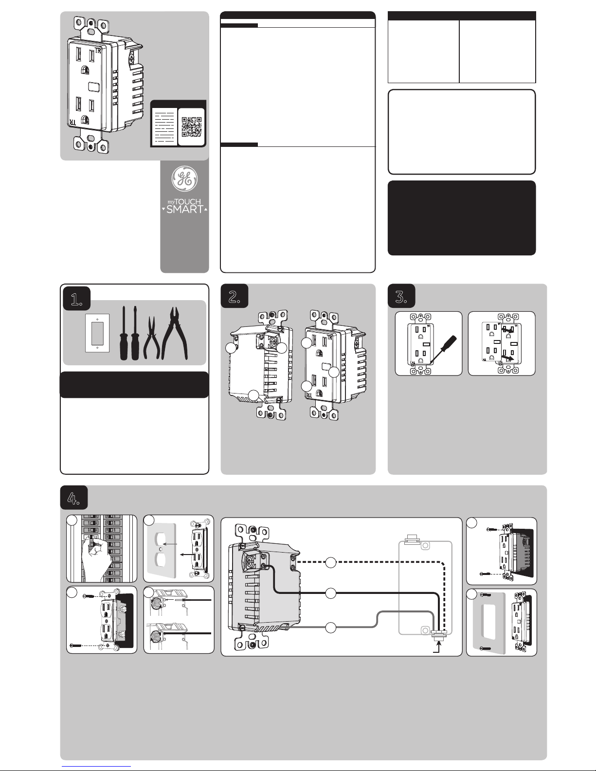
1.
A B
C
D
E
F
READ IT OR WATCH IT
Read instructions or watch easy-to-follow
Wiring
A. Shut off power to the circuit at circuit breaker or fuse box.
IMPORTANT! Verify power to switch box is OFF before continuing.
B. Remove wallplate.
C. Remove the outlet mounting screws and carefully
remove the outlet from the outlet box.
D. Disconnect the wires from the existing outlet. Label wires
according to the previous terminal connection.
Three screw terminals on the Wi-Fi smart outlet are marked:
a. LINE (Hot) — Black (connected to power).
b. NEUTRAL — White.
c. GROUND — Green/Bare.
Match these screw terminals to the wires connected to the existing outlet.
A
a
c
b
From breaker box
F
E
4.
Observe important wiring information
Always follow the recommended wire strip length 5/8in. (16mm) and
wiring combination when making wiring connections. You may consider
consulting an electrician with questions or for professional installation.
UL specifie s that the tighte ning torque for th e screws is 12 lbf-in (14 Kgf-c m).
IMPORTANT! The screw terminals in this receptacle are intended to only be used
with copper wire. Consult a qualified electrician if you have aluminum wiring.
Wire gauge requirements
Use 14AWG or larger wires suitable for at least 90° C for
supplying line (hot), neutral, ground and connections.
E. Insert Wi-Fi Smart Outlet into the box being careful not to pinch or crush
wires. Secure the controlled outlet to the box using the supplied screws.
F. Mount the wallplate. Reapply power to the circuit at
fusebox or circuit breaker and test the system.
A B
C D
HOT
NEURTRAL
GROUND
Insert wires into holes, do not
wrap wires around screws.
Do not remove screws.
SPECIFICATIONS
Voltage: 120VAC, 60Hz
Incandesent: 1000W
Electronic Ballast: 5A
Standard Ballast: 1200VA
Resistive: 1800 (15A)
Motor:1/2HP
Specifications subject to change without notice due to continuing product improvement.
ESPECIFICACIONES
Corriente eléctrica: 120VCA, 60Hz
Incandescente: 1000W
Estabilizador electrónico: 5A
Estabilizador estándar: 1200VA
Carga resistiva: 1800W (15A)
Motor:1/2HP
Las especificaciones están sujetas a cambios sin previo aviso por las constantes mejoras a las que se
someten los productos.

Cambio de la placa frontal
Este paso es opcional. Antes de comenzar, tal vez
necesite cambiar el color de la paleta para que
combine con la placa o la decoración de pared
(incluye la placa blanca y almendra clara).
1. Coloque un destornillador de hoja plana en las
ranuras que se encuentran en cada lado de
la parte frontal y levantela placa frontal.
2. Coloque la nueva placa frontal en su lugar.
3.
A. Línea (con corriente)
B. Neutro
C. Conexión a tierra
D. Tomacorriente siempre
activo
E. Botón manual/programa
F. Tomacorriente
controlado por Wi-Fi
Características principales de su nuevo dispositivo de marca GE
• Un tomacorriente controlado con wifi.
• Un tomacorriente siempre activo
• Control remoto de encendido/apagado a través de la aplicación TouchSmart.
• Botón de anulación de encendido/apagado manual en el tomacorriente
• Este dispositivo de marca GE cuenta con características avanzadas
que le permiten personalizar su experiencia. Estas características
pueden definirse utilizando la aplicación TouchSmart.
2.
Herramientas necesarias
¡IMPORTANTE!
El dispositivo controlado por el tomacorriente inteligente con wifi no
debe exceder los 960 W (dispositivos incandescentes); 15 A, 1800 W
(carga resistiva) o ½ HP (motor). La capacidad máxima total de carga
resistiva combinada de ambos tomacorrientes es de 1800W (15A).
1.
A B
C
D
E
F
4.
Cableado
A. Interrumpa la alimentación al circuito desde el panel de fusibles o el de cortacircuitos.
¡IMPORTANTE! Antes de continuar, compruebe que se haya
INTERRUMPIDO la alimentación eléctrica a la caja del interruptor.
B. Retire la placa.
C. Quite los tornillos de montaje del tomacorriente y, con
cuidado, retire el tomacorriente de la caja.
D. Desconecte los cables del tomacorriente existente. Rotule
los cables según la conexión anterior al terminal.
Hay tres terminales de tornillo en el tomacorriente inteligente con
wifi, los cuales están marcados de la siguiente manera:
a. LINE (Hot) (Línea [con corriente]): negro (conectado al suministro eléctrico)
b. NEUTRAL (Neutro): blanco
c. GROUND (Tierra): verde/pelado
Haga corresponder estos terminales de tornillo con los
cables conectados al tomacorriente existente.
A
a
c
b
From breaker box
F
E
Observe la siguiente información importante sobre el cableado
Siempre siga las longitudes de cable sin aislamiento 16 mm (5/8in.) y la combinación
de cableado que se recomiendan para las conexiones de cableado. Si tiene preguntas
o desea solicitar una instalación profesional, puede consultar a un electricista.
La norma de UL e specifica que e l par de apriete d e los
tornillo s debe ser de 14 Kgf-cm (12 l bf-in).
¡IMPORTANT! Los terminales de tornillo incluidos con este tomacorriente
están diseñados solo para su uso con alambre de cobre. Consulte a
un electricista profesional si sus cables son de aluminio.
Requisitos de calibre del cableado
Use cables de 14 AWG o superior que sean adecuados para una
temperatura de al menos 90 °C para suministro de las conexiones LINE
(Hot) (línea [con corriente]), NEUTRAL (neutro) y GROUND (tierra).
E. Introduzca el tomacorriente controlado por wifi en la caja, con cuidado
de no comprimir o presionar los cables.Asegure bien el tomacorriente
controlado a la caja usando los tornillos provistos.
F. Instale la placa de pared. Reanude el suministro de energía al circuito desde
el panel de fusibles o el de cortacircuitos y pruebe el sistema.
A B
C D
HOT
NEURTRAL
GROUND
Inserte los cables en los orificios, no pase
los cables alrededor de los tornillos.
No quite los tornillos.
 Loading...