

Page 1
MTS5404
40792 v1
07/30/18
In-Wall Wi-Fi
Smart Switch
This device complies with Part 15 of the FCC and Industry Canada license-exempt RSS standards. Operation
is subject to the following two conditions:(1) this device may not cause harmful interference, and (2) this
device must accept any interference received, including interference that may cause undesired operation.
FCC NOTE: The manufacturer is not responsible for any radio or TV interference
caused by unauthorized modifications to this equipment. Such modifications
could void the user’s authority to operate the equipment.
NOTE: This equipment has been tested and found to comply with the limits for a Class B digital device,
pursuant to Part 15 of the FCC Rules. These limits are designed to provide reasonable protection
against harmful interference in a residential installation. This equipment generates, uses and can
radiate radio frequency energy, and if not installed and used in accordance with the instructions, may
cause harmful interference to radio communications. However, there is no guarantee interference
will not occur in a particular installation. If this equipment does cause harmful interference to radio
or television reception, which can be determined by turning the equipment off and on, the user
is encouraged to try to correct the interference by one or more of the following measures:
— Reorient or relocate the receiving antenna.
— Increase the separation between the equipment and receiver.
— Connect the equipment into an outlet on a circuit different from which the receiver is connected.
— Consult the dealer or an experienced radio/TV technician for help.
Important note: To comply with the FCC RF exposure compliance requirements, no change to the
antenna or the device is permitted. Any change to the antenna or the device could result in the
device exceeding the RF exposure requirements and void user’s authority to operate the device.
FCC
RISK OF FIRE
RISK OF ELECTRICAL SHOCK
RISK OF BURNS
CONTROLLING APPLIANCES
• THIS SWITCH IS RATED FOR AND INTENDED TO ONLY BE
USED WITH COPPER WIRE.
• USE 14AWG OR LARGER WIRES SUITABLE FOR AT LEAST 90°
C FOR SUPPLYING LINE (HOT), LOAD, NEUTRAL, GROUND
AND TRAVELER CONNECTIONS.
• DO NOT EXCEED RATINGS
• DO NOT USE TO CONTROL ANY DEVICE WHERE
UNINTENDED OPERATION COULD CAUSE UNSAFE
CONDITIONS (HEAT LAMP, SUN LAMP, ETC.)
• NOT FOR USE WITH MEDICAL OR LIFE-SUPPORT EQUIPMENT
• FOR INDOOR USE ONLY
WARNING
WARNING — SHOCK HAZARD
Turn OFF the power to the branch circuit for the switch and lighting fixture at the service panel. All wiring connections
must be made with the power OFF to avoid personal injury and/or damage to the switch. This device is intended for
installation in accordance with the National Electric Code and local regulations in the United States or the Canadian
Electrical Code and local regulations in Canada. If you are unsure or uncomfortable about performing this installation,
consult a qualified electrician.
MADE IN CHINA
GE IS A TRADEMARK OF GENERAL ELECTRIC COMPANY AND IS
UNDER LICENSE BY JASCO PRODUCTS COMPANY LLC,
10 E. MEMORIAL RD., OKLAHOMA CITY, OK 73114.
This Jasco product comes with a 1-year limited warranty.
Visit www.byjasco.com for warranty details.
Questions? Contact us at 1-800-654-8483
between 7:00AM — 8:00PM CST.
READ IT OR WATCH IT
Read instructions or watch easy-to-follow
video. Scan QR code or visit goo.gl/T6iyFj
SPECIFICATIONS
Voltage: 120VAC, 60Hz
Incandesent: 1000W
Electronic Ballast: 5A
Standard Ballast: 1200VA
Resistive: 1800 (15A)
Motor:1/2HP
Specifications subject to change without notice
due to continuing product improvement.
Getting to know your new Wi-Fi Smart Switch
• Turn ON/OFF manually or through the myTouchSmart app
• Compatible with Amazon Alexa and Google Home
• May be used in single-pole installation or 3-way
wiring configurations
• Compatible with all incandescent, LED, CFL and
halogen lights
• Interchangeable paddle switch — white & light
almond included
• Uses a standard, decorative-size wallplate for single-gang
installations (wallplate not included)
• Screw terminal installation — requires wiring connections
for line (hot), load, neutral and ground. Traveler wire
required for 3-way installation
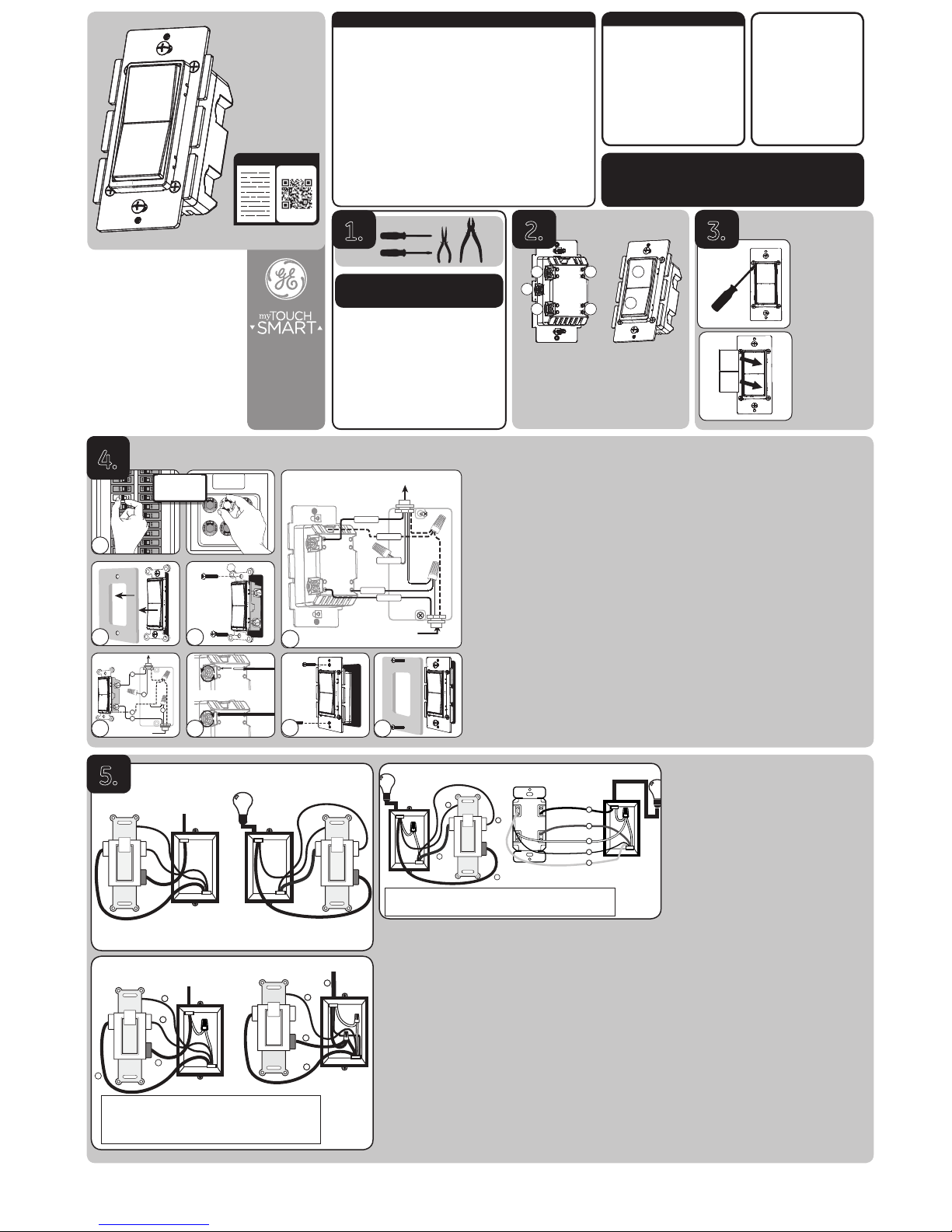
Required tools
IMPORTANT!
The fixture controlled by the Wi-FI Smart Switch must not
exceed 1000W incandescent.
1.
3-way switch wiring
IMPORTANT!
3-way switches can be wired in different ways. These instructions explain the most
common method. If you have difficulty with the instructions or your home wiring, contact
a licensed electrician for assistance.
1. Shut off power to the circuit at circuit breaker or fuse box.
IMPORTANT! Verify power to switch is OFF box before continuing.
2. Remove wallplate.
3. Remove the switch mounting screws.
4. Carefully remove switch from box. DO NOT disconnect the wires yet.
5. Identify “line switch” connected to circuit breaker. Label
wire connected to common terminal “line.”
6. Identify “load switch” connected to lighting/fixture. Label
wire connected to common terminal “load.”
Wire strip length
For attachment using the enclosure’s holes, strip insulation 5/8in. (16mm).
UL specifies that the torque for the screws is 12 lbf-in. (14 Kgf-cm).
Installing the switch on the line side
1. Disconnect the black wire from the black terminal and the
black wire from the brass terminal from the existing switch.
2. Attach the included white jumper wire to the
black wires using the provided wire nut.
3. Connect the free end of the white jumper wire
to the black screw on your existing switch.
Your wires should now look like Figure 2.
4. Carefully replace the switch into the box ensuring
the wires are not pinched or crushed. Secure
the switch using the mounting screws.
Installing the timer on the load side
1. Remove the switch you intend to replace from the wall
and label the wires for future reference (see Figure 3).
2. Connect the load wire to the load terminal on the timer. All
terminal screws should be tightened to 12lbf-in. (14Kgf-cm).
3. Connect the line wire to the line terminal on your timer.
4. Connect the copper or green ground wire
to your timer’s ground terminal.
5. Connect the traveler wire, most likely red, to
the traveler terminal on your timer.
6. Connect the neutral wire from the switch box to the
neutral terminal of the timer. There may be several
neutral wires bound together with a wire nut in
the back of the switch box. Add the neutral jumper
wire to the bundle and tighten the wire nut.
7. Install timer into wire box.
8. Turn breaker on.
9. The blue indicator light located under the ON/OFF
paddle should blink rapidly. If the blue light is not
flashing on, turn off the breaker, verify there is no
power to the Wi-Fi timer, switch the wires in the line
and traveler terminals, and tighten the screws.
10. Reinstall the Wi-Fi timer in the switch box.
11. Turn on breaker.
12. Verify the blue indicator light blinks rapidly.
Single-switch wiring
Removing existing switch
Before you start, you may wish to change the paddle color to
match your wallplate or décor. Please return to Section 3.
A. Shut off power to the circuit at circuit breaker or fuse box.
IMPORTANT! Verify power to switch box is OFF before continuing.
B. Remove wallplate.
C. Remove the switch mounting screws.
D. Carefully remove the switch from the switch
box. DO NOT disconnect the wires.
Up to five screw terminals on the switch are marked:
a. GROUND — Green/Bare.
b. LOAD — Black (connected to lighting).
c. LINE (Hot) — Black (connected to power).
d. TRAVELER — Red.
e. NEUTRAL — White.
Match these screw terminals to the wires connected to the existing switch.
E. Disconnect the wires from the existing switch. Label wires
according to the previous terminal connection.
Installation
Wire strip length:
For attachment using the enclosure’s hole,: strip insulation 5/8in. (16mm)
UL specifies that the tightening torque for the screws is 12 lbf-in (14 Kgf-cm).
F. Connect the green or bare copper ground wire to the ground terminal.
I. Connect the black wire that goes to the light to the terminal marked load.
II. Connect the black wire that comes from the electrical
service panel (hot) to the terminal marked line.
III. Connect the white wire to the neutral terminal (use a
jumper wire if needed). Often, the neutral wire can be found
in the back of the switch box connected with a wire nut .
There may be several neutral wires bound together.
Note:
The traveler terminal is only used for 3-way installations.
V. Insert switch into the switch box being careful not to pinch or crush wires.
G. Secure the switch to the box using the supplied screws.
H. Mount the wallplate. Reapply power to the circuit at fuse box
or circuit breaker and test the system.
The blue indicator light located under the ON/OFF paddle
should blink rapidly. If the blue light is not flashing on, turn off
the breaker, verify there is no power to the Wi-Fi timer, switch the
wires in the line and traveler terminals, and tighten the screws.
A
B C
C
A
D
B
E
D
E
G
H
Line
Ground
LINE SIDE (HOT) LOAD SIDE
H H H H
Load
In a typical 3-way application there are two 3-way switches. The switch on the line (hot)
side has the common terminal tied to 120VAC. The switch on the load side has the
common terminal tied to the load the switches turn on and off.
CC
5.
FIGURE 2 - LINE SIDE AFTERFIGURE 1
-
LINE SIDE SWITCH
2
1
3
Line
H H
4
Ground
2
5
4
Ground
1
Line
H
H
1. Black Wire - Black Screw - Line
2. Red Wire - Brass Screw - Traveler
3. Black Wire - Brass Screw - Traveler
4. Copper Wire - Green Screw - Ground
5. Jumper Wire - Brass Screw - Line + Load + Jumper in wire nut
Typical Wiring Schematic
for 3-Way Installation
TRAVELER
LOADLINE
NEUTRAL
Load
FIGURE 4 - WI-FI SWITCH ON LOAD SIDE
Load
Neutral (White)
Traveler (Line)
Ground
Traveler (Red)
3
4
2
1
5
FIGURE 3
-
LOAD SIDE SWITCH
3
1
2
H H
Load
4
GROUND
1. Black Wire - Black Screw - Load
2. Black Wire - Brass Screw - Line
3. Red Wire - Brass Screw - Traveler
4. Copper/Green Wire - Green Screw - Ground
5. White Wire - Neutral
A. Ground (Green/Bare)
B. Load (Black)
C. Line (Black)
D. Traveler (Red/Other)
E. Neutral (White)
F. Top rocker — Press &
release to turn device
ON, press & hold for 10
seconds to reset Wi-Fi
device to factory specs
G. Bott om rocker —
Press & release to
turn device OFF
G
F
E
C
B
A
D
2.
3.
To change the paddle
This step is optional.
Before installation,
you may want to
change the color of the
paddle to match your
wallplate or décor.
1. Insert a small, flatblade screwdriver into
either groove at the
top of the paddle, and
apply gentle pressure
to remove the paddle.
2. Align the new paddle
with the bottom of
the Wi-Fi device and
press it into place.
OR
OR
4.
From Breaker Box
Out to Light (Load)
LOAD
NEUTRAL
GROUND
LINE
TRAVELER
From Breaker Box
Insert wires into holes, do not
wrap wires around screws.
Do not remove screws.
F
TOP
Page 2

Interruptor de pared
inteligente con wifi
Este dispositivo cumple con las Especificaciones del apartado 15 de las normas de la FCC y con las
especificaciones de las normas radioeléctricas (RSS) del Ministerio de Industria de Canadá aplicables a
aparatos exentos de licencia. El funcionamiento está sujeto a las siguientes dos condiciones: (1) este
dispositivo no debe provocar interferencia perjudicial, y (2) este dispositivo debe aceptar toda interferencia
que reciba, incluso la que pudiera causar un funcionamiento no deseado.
NOTA DE LA FCC: El fabricante no se hace responsable de ninguna interferencia de radio o TV ocasionada
por modificaciones no autorizadas efectuadas a este equipo. Dichas modificaciones podrían anular la
autoridad del usuario para utilizar el equipo.
NOTA : Este equipo ha sido probado y cumple con los límites para aparatos digitales de Clase B, de
conformidad con el apartado 15 de las normas de la FCC. Estos límites están diseñados para proveer
protección razonable contra interferencias perjudiciales en una instalación residencial. Este equipo genera,
usa y puede irradiar energía de radiofrecuencias y, si no se instala y usa según las instrucciones, puede
provocar interferencia perjudicial a las radiocomunicaciones. No obstante, no hay garantías de que no
ocurrirá interferencia en una instalación en particular. Si este equipo provoca interferencia perjudicial a la
recepción de radio o televisión, lo que puede determinarse encendiendo y apagando el equipo, se
recomienda que el usuario intente corregir la
interferencia por medio de la implementación de una o más de las siguientes medidas:
— Reorientar o reubicar la antena receptora.
— Incrementar la separación entre el equipo y el receptor.
— Conectar el equipo a un tomacorriente de un circuito diferente del circuito al que está conectado el
receptor.
— Consultar al distribuidor o a un técnico con experiencia en radio/televisión para
solicitar asistencia.
Nota importante: Para cumplir con los requisitos de cumplimiento de exposición de radiofrecuencia de la
FCC, no se permiten cambios a la antena o el dispositivo. Cualquier cambio a la antena o dispositivo podría
hacer que el dispositivo supere los requerimientos de exposición de radiofrecuencia y anular la autoridad del
usuario para operar el dispositivo.
FCC
RIESGO DE INCENDIO
RIESGO DE DESCARGA ELÉCTRICA
RIESGO DE QUEMADURAS
CONTROL DE EQUIPOS ELECTRODOMÉSTICOS
• ESTE INTERRUPTOR HA SIDO CLASIFICADO PARA USARSE
EXCLUSIVAMENTE CON ALAMBRE DE COBRE Y ESTÁ
DISEÑADO PRECISAMENTE PARA ESE TIPO DE ALAMBRE.
• USE CABLES DE 14 AWG O SUPERIOR QUE SEAN ADECUADOS
PARA UNA TEMPERATURA DE AL MENOS 90 °C PARA
SUMINISTRO DE LAS CONEXIONES LINE (HOT) (LÍNEA [CON
CORRIENTE]), LOAD (CARGA), NEUTRAL (NEUTRO), GROUND
(TIERRA) Y TRAVELER (PUENTE).
• NO SUPERE LOS VALORES NOMINALES ELÉCTRICOS
• NO USAR PARA CONTROLAR DISPOSITIVOS EN LOS QUE EL
FUNCIONAMIENTO NO INTENCIONADO PODRÍA PROVOCAR
SITUACIONES PELIGROSAS (LÁMPARAS DE CALEFACCIÓN,
LÁMPARAS SOLARES, ETC.)
• SE PROHÍBE SU EMPLEO EN EQUIPO MÉDICO O EQUIPO PARA
EL MANTENIMIENTO DE LAS FUNCIONES VITALES
• USE SOLAMENTE EN INTERIORES
ADVERTENCIA
ADVERTENCIA — DESCARGA ELÉCTRICA
Interrumpa el suministro de corriente del circuito de derivación del interruptor y del artefacto de iluminación
en el panel de servicio. Todas las conexiones de cableados deben realizarse con el SUMINISTRO DE CORRIENTE
INTERRUMPIDO para evitar lesiones personales y/o provocar daños al interruptor. Este dispositivo está diseñado para
la instalación conforme al Código de Normas de Electricidad y las reglamentaciones locales en EE. UU. o el Código de
Normas de Electricidad y las reglamentaciones locales en Canadá. Si no está seguro o tiene dudas sobre cómo realizar
la instalación, contacte a un electricista profesional.
READ IT OR WATCH IT
Read instructions or watch easy-to-follow
video. Scan QR code or visit goo.gl/T6iyFj
ESPECIFICACIONES
Corriente eléctrica: 120VCA, 60Hz
Incandescente: 1000W
Estabilizador electrónico: 5A
Estabilizador estándar: 1200VA
Carga resistiva: 1800W (15A)
Motor:1/2HP
Las especificaciones están sujetas a cambios sin
previo aviso por las constantes mejoras a las que
se someten
los productos.
Características principales de su
nuevo dispositivo de marca GE
• ENCENDER/APAGAR y regular los niveles
de atenuación, manual o remotamente a
través de la aplicación myTouchSmart
• Compatible con Amazon Alexa y Google Home
• Se puede utilizar en una instalación monofásica
o en configuraciones de cableado de 3 vías
• Compatible con todas las luces
incandescentes, CFL y halógenas
• Interruptor de paleta intercambiable — el paquete
incluye una paleta blanca y marrón claro
• Utiliza una placa de pared estándar y decorativa
para instalaciones de conexión sencilla (de salida
única) (la placa de pared no está incluida)
• Un LED azul indica la ubicación del
interruptor en habitaciones oscuras
• Instalación de terminales de tornillo — requiere de
conexiones de cables para Line (Hot) (Línea [con corriente]),
Load (carga), Neutral (neutro) y Ground (tierra). Se
requiere un cable puente para instalaciones de 3 vías
Herramientas necesarias
¡IMPORTANTE!
El accesorio controlado por el interruptor inteligente con wifi
no debe ser superior a 1000 W iluminación incandescente.
1.
A. Tierra (Verde/Pelado)
B. Carga (Negro)
C. Línea (Negro)
D. Puente (Rojo/Otro)
E. Neutro (Blanco)
F. Interruptor basculante
superior — Presione y
suelte para ENCENDER
el dispositivo; mantenga
presionado durante
diez (10) segundos
para restablecer el
dispositivo con wifi a
las especificaciones
de fábrica
G. Int errupt or basculante
inferior — Presione y
suelte para APAGAR
el dispositivo
G
F
E
C
B
A
D
2.
Cómo cambiar
la paleta
Este paso es opcional.
Antes de comenzar, tal
vez necesite cambiar
el color de la paleta
para que combine
con la placa o la
decoración de pared.
1. Inserte un
destornillador de hoja
plana en una de las
ranuras de la parte
superior de la paleta y
presione suavemente
para retirar la paleta.
2. Alinee la nueva paleta
con la parte inferior
del dispositivo con
wifi y presione para
colocarla en su lugar.
HECHO EN CHINA
GE es una marca comercial de General Electric Company con
licencia otorgada a Jasco Products Company LLC,
10 E. Memorial Rd., Oklahoma City, OK 73114.
Este producto de Jasco tiene una garantía de por vida limitada. Visite www.byjasco.compara conocer
los detalles de la garantía.
¿Preguntas? Comuníquese al 1-800-654-8483 entre las
7:00 a. m. y las 8:00 p. m. CST (hora central estándar).
Cableado del interruptor de 3 vías
IMPORTANTE:
Los interruptores de 3 vías se pueden cablear de diferentes maneras. Estas instrucciones
detallan los métodos más comunes. Si tiene dificultades con estas instrucciones o con los
cables eléctricos de su vivienda, contacte a un electricista profesional para obtener ayuda.
1. Interrumpa el suministro de energía al circuito desde el
panel de fusibles o el de cortacircuitos.
IMPORTANTE: Antes de continuar, compruebe que se ha INTERRUMPIDO
la alimentación eléctrica a la caja del interruptor.
2. Quite ambas placas de la pared.
3. Retire los tornillos de montaje del interruptor.
4. Saque ambos interruptores de sus respectivas cajas con
cuidado. NO desconecte los cables todavía.
5. Identifique el interruptor conectado al panel de fusiles. Este es el “Interruptor
de línea”. Rotule el cable conectado a la terminal común, ‘LÍNEA’.
6. Identifique el interruptor conectado al aparato/dispositivo de iluminación. Este es el
“Interruptor de carga”. Rotule el cable conectado a la terminal común, ‘CARGA’.
Instalación del interruptor en el lado line (línea)
1. Desconecte el cable negro del terminal negro y el cable
negro del terminal de latón del interruptor existente.
2. Conecte el cable puente blanco incluido a los cables
negros utilizando el empalme de cables provisto.
3. Conecte el extremo libre del cable puente blanco al
tornillo negro del interruptor existente. Los cables
ahora deben verse como se muestra en la Figura 2.
4. Vuelva a colocar con cuidado el interruptor en la
caja y verifique que los cables no se encuentren
comprimidos ni presionados. Asegure el
interruptor utilizando los tornillos de montaje.
Instalación del temporizador en el lado load (carga)
1. Retire el interruptor que desea reemplazar de la pared y
rotule los cables para referencia futura (ver Figura 3).
2. Conecte el cable load (carga) al terminal load
(carga) del temporizador. Todos los tornillos del
terminal deben ajustarse a 12 lbf-in (14 Kgf-cm).
3. Conecte el cable line (línea) al terminal
line (línea) del temporizador.
4. Conecte el cable de cobre o el cable ground (tierra)
verde al terminal ground (tierra) del temporizador.
5. Conecte el cable traveler (puente), probablemente
rojo, al terminal traveler (puente) del temporizador.
6. Conecte el cable neutral (neutro) blanco de la
caja del interruptor al terminal neutral (neutro) del
temporizador. Es posible que existan varios cables
neutros amarrados con un empalme de cables en la
parte posterior de la caja del interruptor. Agregue el
cable puente al grupo y ajuste el empalme de cables.
7. Coloque el temporizador en la caja de cables.
8. Encienda el disyuntor.
9. La luz indicadora azul ubicada debajo de la paleta de
ENCENDIDO/APAGADO debe parpadear rápidamente.
Si la luz azul no está encendida, apague el disyuntor,
verifique que el suministro al temporizador con wifi
esté desconectado, cambie los cables en los terminales
line (línea) y traveler (puente), y ajuste los tornillos.
10. Vuelva a colocar el temporizador con
wifi en la caja del interruptor.
11. Encienda el disyuntor.
12. Verifique que la luz indicadora azul parpadee rápidamente.
Línea
Tierra
LADO DE LA LÍNE (VIVA) LADO DE LA CARGA
H H H H
Carga
En una aplicación típica de 3 vías hay dos interruptores de 3 vías. El interruptor en el
carga tiene el común unido a la carga que los interruptores apagan y encienden.
lado línea (vivo) tiene una terminal común unida a 120VAC. El interruptor en el lado de la
CC
5.
FIGURA 2 - LADO LINE (LÍNEA) DESPUÉSFIGURA 1
-
INTERRUPTOR DEL
LADO LINE (LÍNEA)
2
1
3
Línea
H H
4
Tierra
2
5
4
Tierra
1
Línea
H
H
1. Cable negro, tornillo negro, línea
2. Cable rojo, tornillo de latón, puente
3. Cable negro, tornillo de latón, puente
4. Cable de cobre, tornillo verde, tierra
5. Cable puente, tornillo de latón, línea + carga + puente en empalme de cables
Esquema de cableado típico
para una instalación de 3 vías
TRAVELER
LOADLINE
NEUTRAL
Carga
FIGURA 4 - INTERRUPTOR CON WIFI EN EL
LADO LOAD (CARGA)
Carga
Neutro (Blanco)
Viajero (Línea)
Tierra
Viajero (Rojo)
3
4
2
1
5
FIGURA 3
-
INTERRUPTOR DEL LADO
LOAD (CARGA)
3
1
2
H H
Carga
4
GROUND
1. Cable negro, tornillo negro, carga
2. Cable negro, tornillo de latón, línea
3. Cable rojo, tornillo de latón, puente
4. Cable de cobre/verde, tornillo verde, tierra
5. Cable blanco, neutro
A
B C
C
A
D
B
E
D
E
G
H
A
OR
O
Salida al dispositivo
de iluminación
(carga)
CARGA
NEUTRO
TIERRA
LINEA
PUENTE
From Breaker Box
Inserte los cables en los orificios, no pase
los cables alrededor de los tornillos.
No quite los tornillos.
F
4.
Cableado del interruptor monofásico
Cómo retirar un interruptor existente
Antes de comenzar, tal vez necesite cambiar el color de la paleta para que
combine con la placa o la decoración de pared. Continúe con la sección 3.
A. Interrumpa el suministro de energía al circuito desde
el panel de fusibles o el de cortacircuitos.
IMPORTANTE
: Antes de continuar, compruebe que se ha
INTERRUMPIDO la alimentación eléctrica a la caja del interruptor.
B. Quite la placa de la pared.
C. Retire los tornillos de montaje del interruptor.
D. Saque el interruptor de la caja con cuidado. NO desconecte los cables.
Están marcados hasta cinco terminales de tornillo en el interruptor:
a. GROUND (TIERRA) — Verde/Pelado
b. LOAD (CARGA) — Negro (conectada al dispositivo de iluminación)
c. LINE (Hot) (LINEA [con corriente])— Negro (conectada al suministro
eléctrico)
d. TRAVELER (PUENTE)— Rojo/Otro (solo en instalaciones de 3 vías)
e. NEUTRAL (NEUTRO) — Blanco
Haga corresponder estos terminales de tornillo con los
cables conectados al interruptor existente.
E. Desconecte los cables del interruptor existente. Tome la precaución
de rotular los cables según la conexión anterior al terminal.
Instalación
Longitud de cable sin aislamiento:
Para conectar en terminales de tornillo: pelar 1” (25 mm) del aislamiento.)
La norma de UL especifica que el par de apriete de los
tornillos debe ser de 14 Kgf-cm (12 lbf-in).
F. Conecte el cable de cobre verde o pelado de conexión
a tierra al terminal ground (tierra).
I. Conecte el cable negro que va al dispositivo de
iluminación al terminal marcado load (carga).
II. Conecte el cable negro que viene del panel de servicio eléctrico
(Hot) (con corriente) al terminal marcado line (línea).
III. Conecte el cable blanco al terminal NEUTRAL (neutro) (use un cable
puente, de ser necesario). Muchas veces, el cable neutro se puede
encontrar en la parte trasera de la caja del interruptor, conectado con
un empalme de cable. Puede haber varios cables neutros amarrados.
Nota:
El terminal puente solo se utiliza en instalaciones de 3 vías.
V. Introduzca el interruptor en la caja del interruptor, teniendo
cuidado de no comprimir o presionar los cables.
G. Asegure bien el interruptor a la caja usando los tornillos que se suministran.
H. Coloque la placa de la pared. Reanude el suministro de energía al circuito
desde el panel de fusibles o el de cortacircuitos y pruebe el sistema.
La luz indicadora azul ubicada debajo de la paleta de ENCENDIDO/
APAGADO debe parpadear rápidamente. Si la luz azul no está
encendida, apague el disyuntor, verifique que el suministro al
temporizador con wifi esté desconectado, cambie los cables en
los terminales line (línea) y traveler (puente), y ajuste los tornillos.
3.
TOP
 Loading...