

Page 1
N D
B
N G
SYSTEM
Operating
Instructions
Page 2
Page 3

Thank you for purchasing the GBC DocuBind P400. This system
features our new exctusive Radial Bind design. This design
enables you to assemble your document as you punch. making
it easier to load paper onto the binding comb than previous
systems! The DocuBind P400 advanced punching technology
also makes it easier to punch more paper at once while
providing grealer reliability.
A. GETTING STARTED
1. Firmly push the female end of the power cord into the
power cord receptacle (A) located on the back of the
machine
h CAUTIDN: Make sure this step is complete prior to
~ plugging the male end of the power cord into a power
receptacle .
2. Plug the male end of the power cord into an appropriate
power receptacle.
3. Firmly attach foot pedal cord to receptacle located on back
of machine.
B. DETERMINE SHEET WIDTH
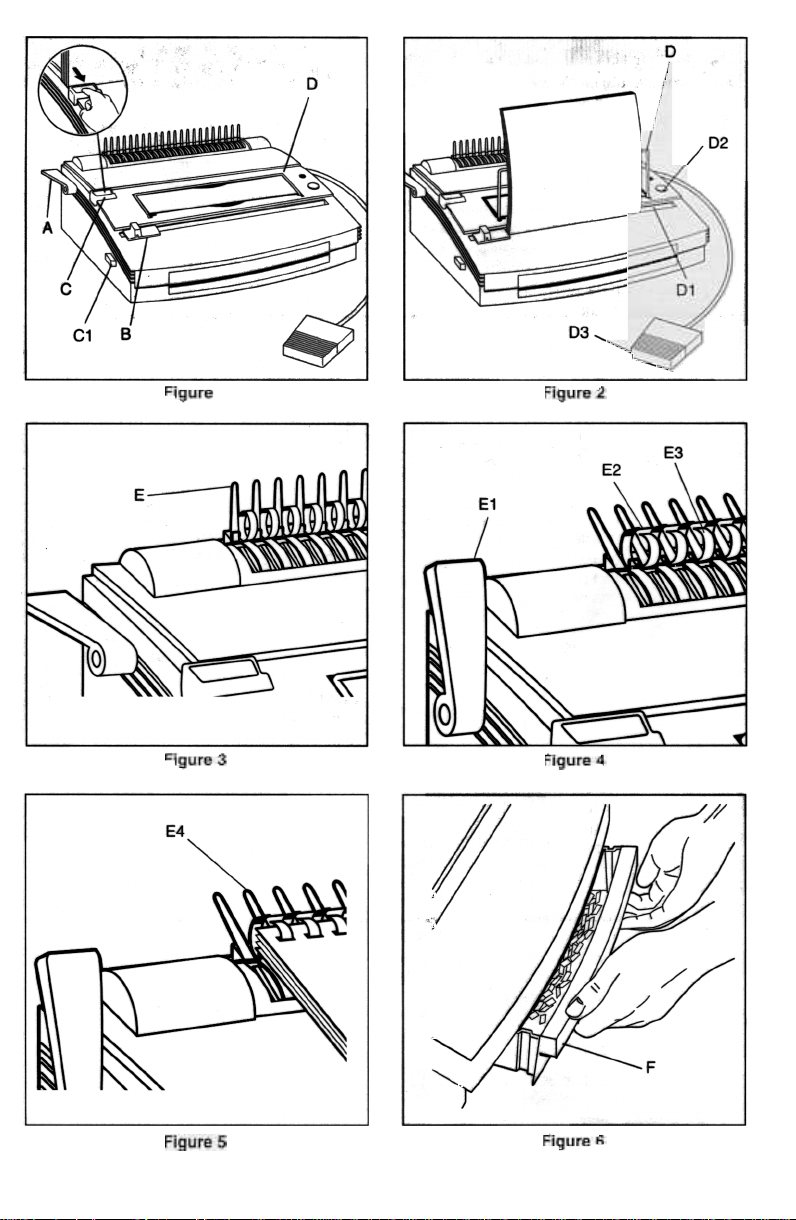
1. Set Edge Guide (B) to paper size you wish to bind (11 ",
8-1/2" letter size, 11-1/4" oversized cover, A4 ring, A5,
Japan A4) (see figure 1 ). When using oversized covers, set
the Edge Guide on Covers, punch all of the covers for your
job and set aside. Move the Edge Guide back to the 11 "
setting to punch your contents then bind.
2. Raise lid on cover (0), and pull up appropriate selector
pins to disengage punch pins that may nick the edge of
your sheet. To determine which pins should be pulled up
follow the punch steps indicated in section "0" using blank
test paper
C. DETERMINE PLASTIC CDMB SIZE
1. Slide the Binder Sizer open (C) (see figure 1).
2. Place document including covers behind Binder Sizer.
3. Release the Binder Sizer and select the comb binding
element that corresponds with the size shown by guide.
Only comb sizes up to 1" (25 mm) are shown. Your
OocuBind can bind documents up to 425 sheets, or 2"
(50 mm) comb size. For best results, always use GBC
brand covers with GBC color-coordinated binding combs.
4. Adjust the Punch Back Guide (C1) to the setting that
corresponds with the plastic comb size to be used.
D. PUNCHING PAPER (see figure 2)
1. UtI the Wire Paper Suppol1 (0) into place (optional).
2. Align sheets or covers and insel1 edge to be bound into
punch throat (01 ).
3. Jog the sheets until they are flush against the edge guide
and the bottom of the punch throat. Allow the paper to rest
against the Wire Paper Support, or, you may
prefer to hold the sheets in place with one hand.
4. To punch, press the PUNCH ~ button (D2) or depress
the foot pedal (D3). The DocuBind P400 punches up to 21
sheets of 20 Ib./80 gram paper at once. Punch only TWO
clear covers at a time to prevent jams and excessive wear.
5. If you try to punch too many sheets GBC's patented "Jam
Stopper" safeguard feature will automatically stop and
reverse the punch die. At this time the yellow LED indicator
will temporarily flash. Remove the paper from the punch
throat and decrease it's thickness before trying to punch
again.
E. BINDING
1. Place a Plastic Comb Binding Element behind the Vertical
Comb (E) with the open portion of element facing you (see
figure 3).
2. Rotate the Bind Lever up (E1) toward you until the Comb
Binding Element (E2) opens sufficiently to insert your
document (see figure 4).
3. Thread front cover finished side facing down (see figure 5),
onto open Binding Element Fingers (E3). Thread pages,
front facing down, onto element. Repeat for large documents as required. Place the back cover, finished side
facing upward on open Binding Element Fingers last.
4. Push the Bind Lever away from you back to its original
position to close the binding element.
5. Remove book by lifting upward. Your presentation is
now complete!
6. Once you become familiar with your DocuBind P400,
you will find that you can bind as you punch, increasing
your productivity.
F. EMPTY CHIP DRAWER
1 Empty Chip Drawer (F) after repeated use. Pull drawer
gently toward you to open. When putting back in, the
drawer will snap into place (see figure 6).
G. SERVICE
Should your DocuBind require service contact:
Quartet, a GBC Company
5700 Old Orchard Road
Skokie, IL 60077 USA
1-800-541-0094
http://www.quartetgbc.com
SPECIFICATIONS
Dimensions Punch Capacity" 21 sheets of 20 Ib" paper
Weight
Electrical Power"
18" (W) x 81/2" (H) x 16" (0)
457mm x 216mm x 406mm
351bs. (15.5 kg.)
115V AC. 60 Hz. 4.3 amps, 130
watts or 230V AC. 50Hz.
1.3 amps
21 sheets of 80gm2 paper
Bind Capacity" 425 sheets or 2"
(50mm)
Maximum Sheet Width" 11.7" (297mm A4)
Dis-engagable Punch Pins: 11
3
Page 4

SAFETY MESSAGES
Your safety as well as the safety of others is important to
GBG. In this Operator Manual and on the product are important safety messages. Read these messages carefully.
.i\. The safety alert symbol precedes each safety message
..in this Operator Manual. This symbol indicates a
potential personal safety hazard that could hurt you or
others, as well as cause product or propertY damage.
The following warning is found on this unit:
This safety message means you could be seriously hurt or
killed if you open the product and expose yourself to
hazardous voltage.
The following symbols appear on this product. and their
meanina is as followso
El3PU-NCH
~ WARNING: For your protection, do not connect the
..DocuBind P400 to electrical power until you read these
instructions completely. Keep these instructions in a convenient location for future reference. To guard against injury,
the following basic safety precautions must be observed in
the set-up and use of this product.
IMPORTANTSAFEGUAROS
GENERALSAFEGUAROS
.Use the DocuBind P400 only for its intended purpose of
punching and binding paper and covers according to the
indicated specifications.
.Do not place anything in the punch opening of the machine
other than paper and cover stock.
.Place unit on a secure, stable work area to prevent the
machine falling and possibly causing personal injury and
damage to the unit.
.Follow all warnings and instructions marked on the product.
.Lift the machine from the bottom, not the cover.
.Do not lift the machine by the cover or paper holder wire.
ELECTRICAL SAFEGUARDS
The DocuBind P400 must be connected to a supply voltage
corresponding to the electrical rating of the machine as indicated on the serial/rating plate or in this manual
1'1. CAUTION: THE POWER RECEPTACLE MUST BE LOCATED
..NEAR THE EOUIPMENT AND BE EASILY ACCESSIBLE.
r.. CAUTION: IN CASE OF EMERGENCY, USE THE POWER
..CORD AS A MAIN DISCONNECT DEVICE!
.Unplug the DocuBind P4OO before moving it, or when it is
not in use for an extended period of time,
.Do not operate with a damaged supply cord or plug, after it
malfunctions, or after it has been damaged in any manner.
.Do not overload electrical outlets beyond their capacity as
this can result in fire or electrical shock.
.Do not alter attachment plug. Plug is configured for the
appropriate electrical supply.
.The unit is intended for indoor use only.
.Never push objects into this product through cabinet slots.
Do not spill liquid of any kind on this product.
.Do not operate if the product has been exposed to rain or
water.
SERVICE
Do not attempt to service or repair the DocuBind P400 your-
self. Unplug the unit and contact an authorized GBC service
representative for exchange or repair.
CLEANING
A CAUTION: Unplug this product before cleaning.
Wipe exterior only with a damp cloth. Do not use detergents
or solvents
The following notes apply only to the units rated 230V 50Hz.
MAIN CORDSET SELECTION (FDR 230VAC MACHINES ONLY)
When choosing a detachable line cord for use with the
OocuBind P40O, always observe the following.
The cordset consists of three components; the attachment
plug, cordage and appliance inlet. Each of these components
must meet European regulatory approvals for safety.
The following minimum electrical ratings for the specific
cordset are published for safety purposes. DO NOT USE
CORDSETS THAT DO NOT MEET THE FOLLOWING MINIMUM
ELECTRICAL REQUIREMENTS.
PLUG: 3A, 250 volts, 50/60 Hz, Class 1,3 conductor,
European safety agency approved.
CORDAGE: Type H05W-F3GO.75, Harmonized ( <] HAR 1;> ).
The" <] I>" symbols indicate cordage approved to appropriate European standard (NOTE. "HAR" may be substituted
by the approval mark of the European safety agency which
approved the cordage. An example would be" <]VOE I>-".
APPLIANCE CONNECTOR: 3A, 250 volts, 50/60 Hz, European
safety approved, Type IEC 320. Cordset shall not exceed 3
meters in length. Cordset with component electrical ratings
greater than the minimum specified electrical ratings may be
substituted.
Q UARTET111
8
.AQec:COMPANY
SKOKIE, Il60077
hnp://WWW.qu3otetgbc.com
 Loading...