

Page 1
25&$,9,PDJH7U DQVIHU
/DPLQDWRU2SHUDWLRQ
0DQXDO
© 1998 GBC Pro-Tech
Do not duplicate without written permission
N
E
C
Y
G
S
T
R
O
E
P
M
E
A
R
R
S
E
U
T
A
D
T
O
'
U
N
R
G
E
C
E
N
%
100
90
80
70
60
50
40
30
20
10
%
100
90
80
70
60
50
40
30
20
10
%
100
90
80
70
60
50
40
30
20
10
%
100
90
80
70
60
50
40
30
20
10
P
R
O
-T
E
C
H
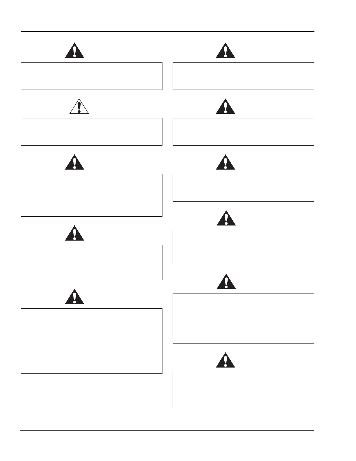
WARNING
ACHTUNG
MISE EN GARDE
Part Number 930-009 Rev. A
N
E
C
Y
G
S
T
R
O
E
P
M
E
A
R
R
S
E
U
T
A
D
T
O
'
U
N
R
G
E
C
E
N
psi
100
kPa
90
700
80
630
70
560
60
490
50
420
40
350
30
C
A
280
20
L
3
2
0
0
210
10
140
70
SAFETY
INSTRUCTIONS
SICHERHEITSRICHTLINIEN
CONSIGNES DE
SÉCURITÉ
C
A
L
3
2
0
0
4
0000
1234
ORCA IV™
PRO-TECH
GBC Pro-Tech
4151 Anderson Road
De Forest, Wisconsin 53532
Tel: 608-246-8844
Fax: 608-246-8645
Page 2

ORCA-IV Image Transfer Laminator Operation Manual
ii
© GBC Pro-Tech 1998 October
The information in this publication is provided for r efer en ce and is believed to be accurate
and complete. GBC Pro-T ech is not liable for errors in this publication or for incidental or
consequential dama ge in connection with th e furnishing or use of the informatio n in this
publication, including, but not limited to, any implied warranty of fitness or merchantability for any particular use.
GBC Pro-Tech reserves the right to make changes to this publication and to the products
described in it witho ut n otice. All specifica tions and in forma tion concer ning products are
subject to change without notice.
Reference in this publication to information or products protected by copyright or patent
does not convey any license under the rights of GBC Pro-Tech or others. GBC Pro-Tech
assumes no liability arising from infringements of patents or any othe r rights of third
parties.
This manual is copyri ghted ©1998 by GBC Pro-Tech. All rights reserved. The inf orma t io n
contained in this manual is proprietary and may not be reproduced, stored, transmitted, or
transferred, in whole or in part, in any form without the prior a nd express written permission of GBC Pro-Tech.
Page 3

ORCA-IV Image Transfer Laminator Operation Manual
© GBC Pro-Tech 1998 October
iii
7DEOHRI&RQWHQWV
6HFWLRQ6DIHW\
Caution/Warning Label Locations....................................................................................1-5
6HFWLRQ,QVWDOODWLRQ
Preinstallation Checklist...................................................................................................2-1
Unpacking........................................................................................................................2-4
Setup ...............................................................................................................................2-5
Leveling ...........................................................................................................................2-5
Startup.............................................................................................................................2-6
6HFWLRQ2SHUDWLRQ
Safety...............................................................................................................................3-1
Audible Signals............................................................................................................3-3
Operator Controls............................................................................................................3-4
Front Control Panel......................................................................................................3-4
Front Clutch/Brake Panel.............................................................................................3-6
Rear Control Panel ......................................................................................................3-8
Rear Clutch/Brake Panel ...........................................................................................3-10
Setup .............................................................................................................................3-11
Loading the Film............................................................................................................3-11
Heating ..........................................................................................................................3-11
Recommended Materials...............................................................................................3-12
Films (Excluding Vinyl Transfer and Overlamination)................................................3-12
Vinyl Transfer and Overlamination Materials.............................................................3-12
Setting the Slitter ...........................................................................................................3-12
Paper Tips......................................................................................................................3-12
Positioning the Film and Centering the Web .................................................................3-13
Film Spacing..................................................................................................................3-14
Operational Tips and Tricks...........................................................................................3-14
Changing Film and Paper. ..... ..... ............................ .... ..... ............................ ..... .... .....3-14
Process Control Charts..................................................................................................3-15
Vinyl T r an sfe r ....................... ..... ..... .... ............................ ..... ..... ............................ .... .....3-15
Setup...................................... ............................ ..... .... ............................ ..... ..... .........3-15
Procedure ......................... ..... ..... .... ............................ ..... ..... ............................ .... .....3-16
Machine Shutdown........................................................................................................3-16
Procedure ..................................................................................................................3-16
Page 4

ORCA-IV Image Transfer Laminator Operation Manual
iv
© GBC Pro-Tech 1998 October
6HFWLRQ0DLQWHQDQFHDQG7URXEOHVKRRWLQJ
Cleaning ..........................................................................................................................4-1
Lubrication.......................................................................................................................4-3
Adjusting the Kick Cable..................................................................................................4-3
Contacting Technical Support...................................... ............................ ..... ..... ..............4- 4
Output Troubleshooting Guide.........................................................................................4-6
6HFWLRQ:DUUDQW\
Limited Warranty..............................................................................................................5-1
Exclusions to the Warranty..........................................................................................5-1
6HFWLRQ6SHFLILFDWLRQV
6HFWLRQ,QGH[
Page 5
ORCA-IV Image Transfer Laminator Operation Manual
Safety
© GBC Pro-Tech 1998 October
1-1
6HFWLRQ6DIHW\
DANGER
WARNING
CAUTION
IMPORTANT
Note
WARNING
DO NOT ATTEMPT TO OPERATE YOUR
ORCA-IV IMAGE TRANSFER LAMINATOR
UNTIL YOU HAVE READ THIS SECTION
CAREFULLY!
Your safety, as well as the safety of others, is important
to GBC Pro-Tech. This section contains important
safety information.
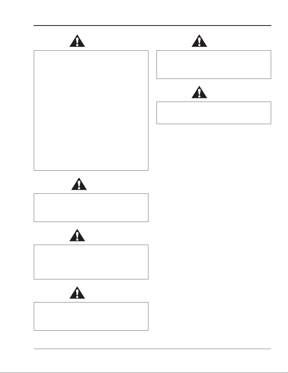
The following symbols are used throughout this manual to indicate warnings and cautions.
Indicates an imminently hazardous situatio n
which, if not avoided, will result in death or
serious inj ury.
The GBC Pro-Tech ORCA-IV is a powerful machine
that is designed for vinyl transfer and over-lamination.
The forces required to accomplish these tasks are very
large.
The air-cylinder system used to provide downward
pressure on the top roll is capable of producing forces
greater than 1000 pounds (454kg). This fo rce is appli ed
to any object presented in the opening (called the nip)
between the two rolls.
Use care in lowering the t op main roll and kno w how to
react quickly in an emergency. The laminator roll UP-
DOWN switch is located on the instrument panels.
This switch controls the up and down motion of the top
laminator roll. Before pre ssing this switch to the
DOWN position, ensure that no thing is in the nip area.
If any problem or danger should occur, depressing any
of the emergency buttons stops the rolls from closing
and raises them completely.
☞
To quickly stop the machine in the event of an emergency , press any of the emergency stop b uttons or appl y
force t o eith er kick cab le. T his act ion st ops the mac hin e
completely and raises the rolls.
Indicates a potentially hazardous situation
which, if not avoided, could result in death or
serious inj ury.
Indicates a potentially hazardous situation
which, if not avoided, could result in minor or
moderate injury, or alerts against unsafe
practices, or alerts against actions which could
damage the product.
Indicates important additional information.
The ORCA-IV Image Transfer Laminator has been
designed with safety as a primary consideration. However, you must become thoroughly familiar with the
controls, proper operation, proper service procedures,
and safety features of the image transfer laminator
before using or servicing the unit.
In addition, the rolls of the ORCA-IV can reach temperatures of over 290 °F (143 °C). At these temperatures you can be burned if the rolls are touched during
set-up, operation or servicing.
Opening any door of the image transfer laminator
causes the rolls to slow to 3.0 ft/min (1 m/min).
Do not ever attempt t o overr ide the safet y syst em
on the doors of the machine or the kick cables.
You could get your fingers or arms between the
rolls when they are turning or in the closed
position and you could be crushed or severely
burned.
The machine has a steel cabine t th at is bol te d closed to
isolate the electrical and drive system components for
the safety of the operato r. Only a qualified service technician should open these cabinets.
Page 6
Safety
ORCA-IV Image Transfer Laminator Operation Manual
1-2
© GBC Pro-Tech 1998 October
The machine is equipped with four emergency stop
buttons located on either side of the front and back of
the image transfer laminator. Any of these, if engaged,
stops the machine. To continue operation, all emergency stop buttons must be in the out position and you
must perform the Machine Reset Procedure. See
“Machine Reset Procedure” on page 1-3.
Push any button
to stop the
laminator
Twist each button
to resume
operation - the
button pops out
FRONT
N
E
C
Y
G
S
T
R
O
E
P
M
E
A
R
R
S
E
U
T
A
D
T
O
'
U
N
R
G
E
C
E
N
%
100
90
80
70
60
50
40
30
20
10
%
100
90
80
70
60
50
40
30
20
10
%
100
90
80
70
60
50
40
30
20
10
%
100
90
80
70
60
50
40
30
20
10
P
R
O
-
T
E
C
H
W
A
RN
ING
ACH
TUN
M
IS
G
E
E
N
G
A
R
D
E
Carefully read Operator's
Manual before handling
this machine. Observe
instructions and safety
rules when operating.
©
1
9
9
4
H
C
S
,
In
c
.
8
0
0
-
7
4
8
-
0
2
4
1
R
e
o
r
d
e
r
N
o
.
6
0
0
1
P
T
N
E
C
Y
G
S
T
R
O
E
P
M
E
A
R
R
S
E
U
T
A
D
T
O
'
U
N
R
G
E
C
E
N
psi
100
kPa
90
700
80
630
70
560
60
490
50
420
40
350
30
CAL 3200
280
20
210
10
140
70
CAL 3200
4
0
0
0
0
12
34
ORCA IV™
A
U
S
NOT
E
C
N
E
G
R
U
'
D
T
E
R
R
E
M
E
R
G
E
N
C
Y
S
T
OP
A
E
C
N
E
G
R
U
'
A
U
S
NOT
1
/
4
D
T
E
R
R
E
M
n
r
u
t
A
OP
E
R
G
E
N
C
Y
S
T
Figure 1-1: Using the Emergency Stop Buttons
In addition, the ORCA-IV is equipped with two emergency stop kick cables located at the lower front and
back of the image transfer laminator.
BACK
Emergency
Stop Kick
Cable
N
C
E
Y
G
S
R
T
O
E
P
M
E
A
R
R
S
E
U
T
A
D
T
O
'
U
N
R
G
E
C
E
N
%
1
0
0
9
0
8
0
7
0
6
0
5
0
4
0
3
0
2
0
1
0
%
1
0
0
9
0
8
0
7
0
6
0
5
0
4
0
3
0
2
0
1
0
%
1
0
0
9
0
8
0
7
0
6
0
5
0
4
0
3
0
2
0
1
0
P
R
O
-T
E
C
H
WARNING
ACHTUNG
MISE EN GARDE
Carefully read Operator's
Manual before handling
this machine. Observe
instructions and safety
rules when operating.
©
1
9
9
4
H
C
S
,
I
n
c
.
8
0
0
-
7
4
8
-
0
2
4
1
R
e
o
r
d
e
r
N
o
.
6
0
0
1
-
P
T
P
O
W
E
R
Emergency
Stop Kick
Cable
PRO-TECH
N
C
E
Y
G
S
R
T
O
E
P
M
E
A
R
R
S
E
U
T
A
D
T
O
'
U
N
R
G
E
C
E
N
psi
100
kPa
90
7
80
00
6
70
30
560
60
490
50
420
40
psi
350
30
100
280
20
kP
90
210
10
a
700
80
140
630
70
70
560
6
0
490
50
420
40
350
30
280
20
210
10
140
70
P
R
O
-
T
E
C
H
0
0
00
1
2
3
4
ORCA IV™
PRO-TECH
Figure 1-2: Using the Emergency Stop Kick
Cables
Either of these, if stepped on or kicked, stops the laminator and raises the rolls. To continue operation, press
the kick cable reset button. Then compl ete the Machine
Reset Procedure. See “Machine Reset Procedure” on
page 1-3.
Page 7
ORCA-IV Image Transfer Laminator Operation Manual
Safety
© GBC Pro-Tech 1998 October
1-3
Note
WARNING
IMPORTANT
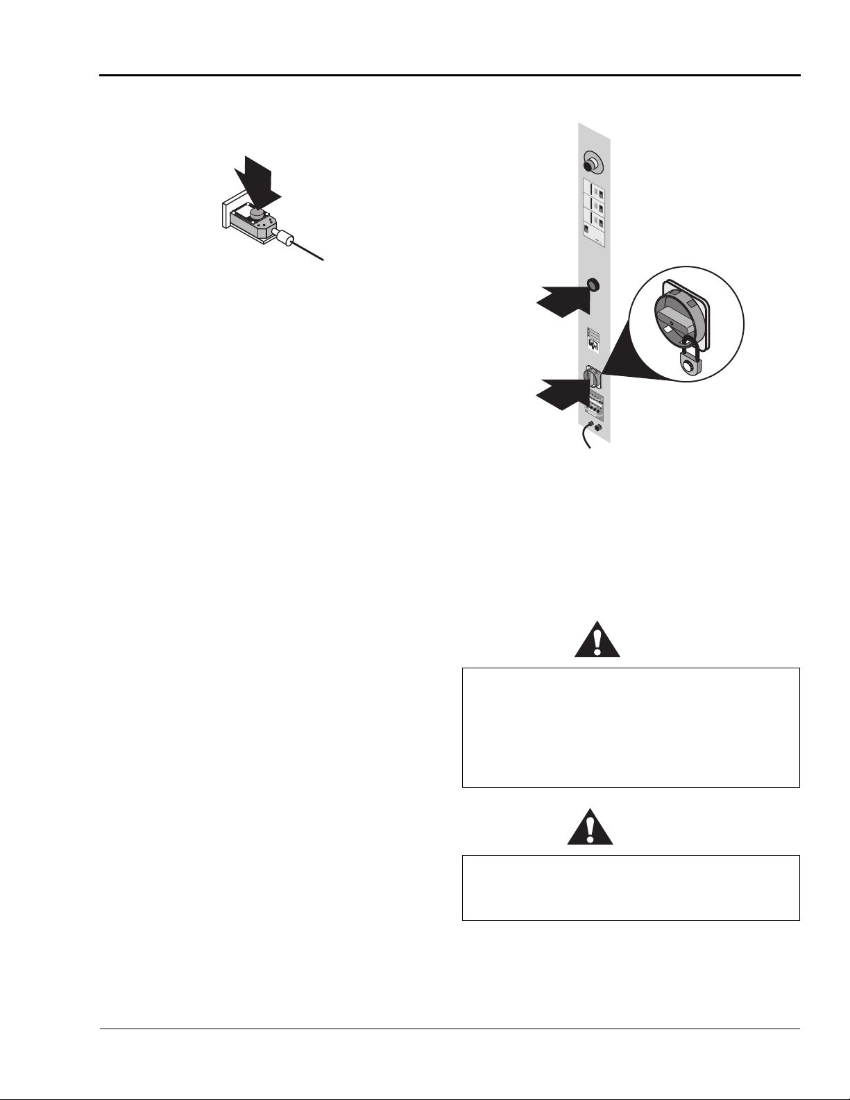
Kick Cable
Reset Button
Figure 1-3: Kick Cable Reset Button
Machine Reset Procedur e
Perform this procedure whenever an emergency stop
button or kick cable is activated or when the power to
the machine is turned on.
1. Make sure all emergency stop buttons and kick
cables are reset.
2. Press the main machine reset button above the
power switch on the back of the machine. See
ure 1-4: Machine Reset Button
.
Fig-
3. Check the web force se ttings to make sure they are
what you require.
4. Turn the heater back on. It is necessary to restart
the heater as all power is turned off when an emergency stop button or kick cable is activated.
5. Lock the shafts by closin g the doors of the machine
and pressing either the shaft locking switch or the
FWD or REV arrow.
N
E
C
Y
G
S
T
R
O
E
P
M
E
A
R
R
S
E
U
T
A
D
T
O
'
U
N
R
G
E
C
E
N
%
1
0
0
9
0
8
0
7
0
6
0
5
0
4
0
3
0
2
0
1
0
%
1
0
0
9
0
8
0
7
0
6
0
5
0
4
0
3
0
2
0
1
0
%
1
0
0
9
0
8
0
7
0
6
0
5
0
4
0
3
0
2
0
1
0
PRO-TECH
Reset
Power
Switch
w/ Lock
Button
WARNING
ACHTUNG
Power
MISE EN GARDE
Switch/
Lockout
POWER
Figure 1-4: Machine Reset Button
Despite the safety features built into the ORCA-IV,
extreme caution must be used when operating or servicing the unit. READ THE FOLLOWING WARN-
INGS AND CAUTIONS BEFORE ATTEMPTING
TO OPERATE OR SERVICE THE ORCA-IV
IMAGE TRANSFER LAMINATOR.
6. Start the motor and increase the speed.
☞
If the display does not have a decimal point in it, the
machine needs to be reset.
Secure long hair so that it cannot get caught in
the machinery. Do not wea r ties, loose fitting
clothing or dangling jewelry while cleaning or
servicing the image tran sfer laminator. These
items can get caught in the nip and choke you or
you can be crushed or burned.
Use a lift to load and unload rolls larger than 50
yards. They can weigh up to 500 lbs and can
crush you.
Page 8
Safety
ORCA-IV Image Transfer Laminator Operation Manual
1-4
© GBC Pro-Tech 1998 October
IMPORTANT
DANGER
IMPORTANT
IMPORTANT
IMPORTANT
IMPORTANT
IMPORTANT
IMPORTANT
IMPORTANT
IMPORTANT
IMPORTANT
Do not operate the image transfer laminator near
water. Y ou can be sev erely shocked, electrocuted
or cause a fire.
Raise the upper main roll when the image
transfer laminator is not in operat ion. P r olonged
contact can damage the rolls.
Remove and lockout power from the image
transfer laminator before servicing. You can be
severely shocked, electrocuted or cause a fire.
Do not use liquid or aeros ol cleaners on the image
transfer laminator. Do not spill liquid of any kind
on the image transfer laminator. You can be
severely shocked, electr ocuted or cause a fir e. Use
only a damp cloth for cleaning.
Use only 80% (or str onger) i sopr opyl alcohol or a
rubber cement eraser to clean the rolls. Harsh
chemicals like toluene, acetone or MEK destroy
the silicone covering of the rolls.
Do not leave the top roll heater on with the roll
raised. Heat builds up in a stationary roll and can
damage it.
Excess pressure can damage the rolls. Always
select the minimum roll pressure necessary to
complete the ta sk.
If silicone adhesive contacts the upper or lower
roll, remove it IMMEDIATELY using 80 %
isopropyl alcohol. It can harden within an hour
and ruin the roll .
Exercise care when cleaning the rolls with
80% (or stronger) isopropyl alcohol:
• Use only in a well ventilated area.
• Wear rubber gloves.
• Use only on cool rolls.
Cleaning heated rolls can ignite the fumes.
The operating environment must be free of dust,
flammable liquids and vapors. You can be
injured by inhaling c hemical vapors. Vapor build
up or stored flammable liquids can cause a fire.
Excessive dust can damage the image transfer
laminator.
Do not use a knife or other sharp instrument
during installation or while servicing the image
transfer laminator. You can cause irreparable
damage to the rolls.
Page 9
ORCA-IV Image Transfer Laminator Operation Manual
Safety
© GBC Pro-Tech 1998 October
1-5
IMPORTANT
WARNING
IMPORTANT
IMPORTANT
IMPORTANT
IMPORTANT
Do not attempt to move the image transfer
laminator across anythi ng other than a fla t, level
surface without trained and qualified riggers.
You can be crushed or seriously injured.
The ORCA-IV Image Transfer Laminator is a
large and heavy piece of equipment. It is
necessary to employ LICENSED RIGGERS
ONLY to move the machine. The image transfer
laminator is not designed to be tipped up or
sideways in any way. Such action disturbs the
exact alignment of the rolling parts of the
machine and requires extensive realignment.
GBC Pro-Tech’s warranty does not cover
malfunction of the equipment due to mis handling
and/or tipping.
GBC Pro-Tech bears no responsibility for
personal injury or damage due to moving the
image transfer laminator improperly.
Do not open the side co ver s of t he mac hine . Onl y
a qualified service technician should remove the
covers. You can be severely shocked,
electrocuted, or crushed.
Never operate the mac hine with s ide covers open.
You can be severely shocked, electrocuted, or
crushed.
ALWAYS USE GOOD SAFETY PRACTICES
WHEN OPERATING OR SERVICING THE IMAGE
TRANSFER LAMINATOR AND KNOW HOW TO
REACT QUICKLY IN AN EMERGENCY.
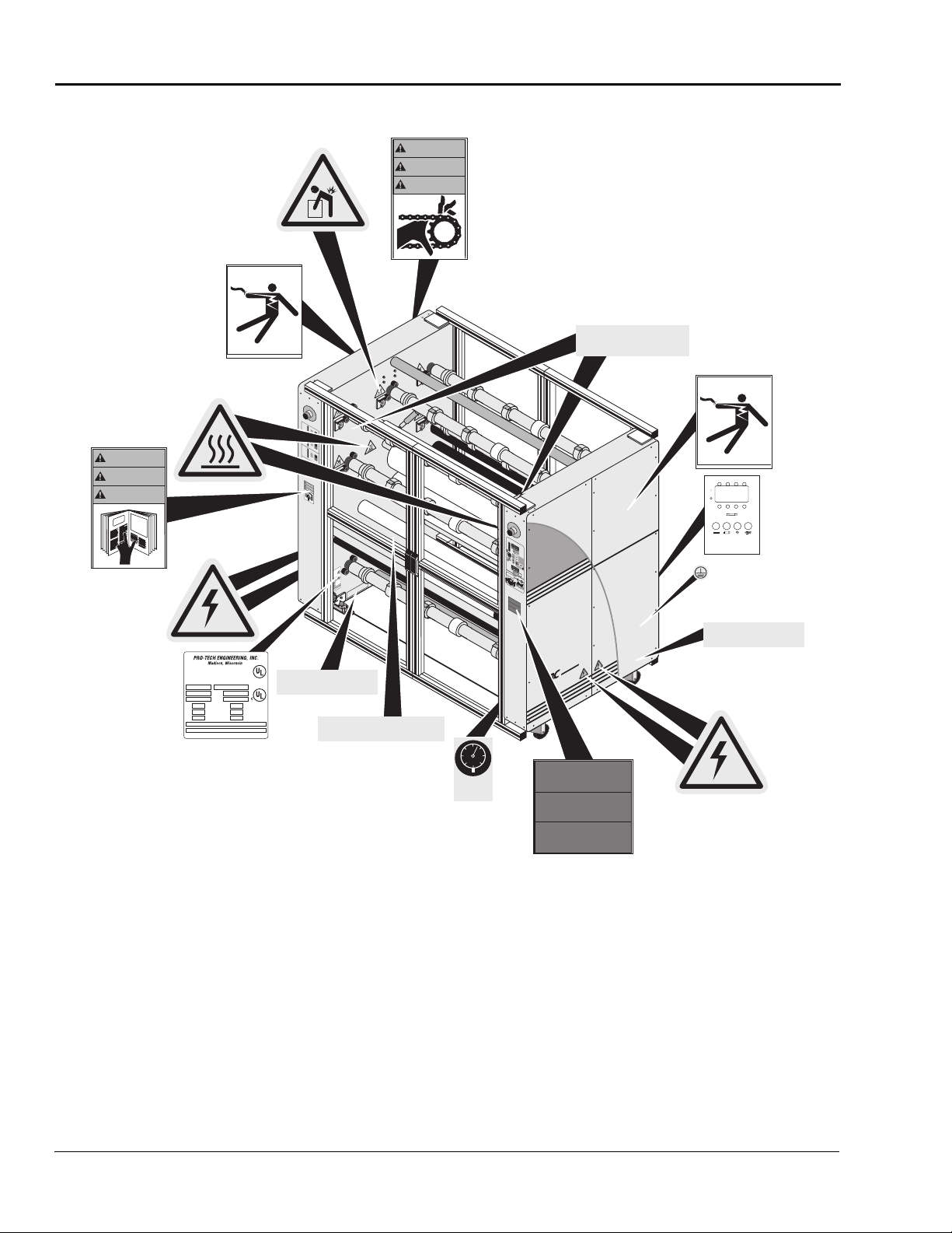
&DXWLRQ:DUQLQJ/DEHO/RFDWLRQV
On your ORCA-IV Image Transfer Laminator are
important safety labels. See Figure 1-5: Locations of
Safety Labels for the location of the se labels.
Only a qualified el ectrician s hould connect power
to the image transfer laminator. You can be
severely shocked, electrocuted or cause a fire if
power is improperly applie d.
Do not operate the image transfer lamin ator if
the power cord is damaged or frayed. You can be
severely shocked, electrocuted or cause a fire.
Contact a qualified electrician to replace the
cord.
Do not allow anything to rest on the power cord.
Do not locate the cord where people can walk on
it. You or others can be severely shocked,
electrocuted or cause a fire.
Page 10
Safety
ORCA-IV Image Transfer Laminator Operation Manual
1-6
© GBC Pro-Tech 1998 October
WARNING
ACHTUNG
MISE EN GARDE
On
Exterior
Panels
One Located At
Each Roll Load
Point (7 Total)
Located
Inside
Cabinet
©1994 Hazard Communication Systems, Inc. 800-748-0241
WARNING
ACHTUNG
Located
Inside
Cabinet
MISE EN GARDE
CAUTION! EXPOSED ROLLER
Can cause personal injury.
Keep hands, long hair, ties, jewelry
and loose clothing away from this area.
Located Inside
Cabinet
N
E
C
Y
G
S
R
T
O
E
P
M
E
A
R
R
S
E
U
T
A
D
T
O
'
U
N
R
G
E
C
E
N
%
100
90
80
70
60
50
40
30
20
10
CAUTION! EXPOSED ROLLER
Can cause personal injury.
%
100
Keep hands, long hair, ties, jewelry
90
and loose clothing away from this area.
80
70
60
50
40
30
20
10
%
100
90
80
70
60
50
40
30
20
10
%
100
90
80
70
60
50
40
30
20
10
P
R
O
-T
E
C
H
WARNING
ACHTUNG
MISE EN GARDE
N
E
C
Y
G
S
R
T
O
E
P
M
E
A
R
R
S
E
U
T
A
D
T
O
'
U
N
R
G
E
C
E
N
psi
100
kPa
90
700
80
630
70
560
60
490
50
420
40
350
30
C
A
280
20
L
3200
210
10
140
70
C
AL
320
0
4
00
00
1
2
3
4
SAFETY
INSTRUCTIONS
SICHERHEITSRICHTLINIEN
CONSIGNES DE
SÉCURITÉ
ORCA IV™
PRO-TECH ENGINEERING, INC.
Model No. Serial No.
Emergency Stop Kick Cables Located Below.
Kick or Step on to Stop Laminating Process.
®
LISTED
I.T.E
6N10
Madison, Wisconsin
®
VAC
Hz
Amps
Phase
Wires
MADE IN U.S.A.
SEE INSTALLATION INSTRUCTIONS
BEFORE CONNECTING TO THE
SUPPLY
©1994 Hazard Communication Systems, Inc. 800-748-0241
6 A 1 A 6 A
24VDC
6 A/250V 1/4 X 1-1/4 IN [ 5 X 20mm ]
1 A/250V 1/4 X 1-1/4 IN [ 5 X 20mm ]
CAUTION
FOR CONTINUED PROTECTION AGAINST RISK OF FIRE,
REPLACE ONLY WITH SAME TYPE AND RATING OF FUSE
Located Inside
Cabinet
Located Inside
Cabinet
HIGH LEAKAGE CURRENT!
Earth connection essential before
connecting supply
Model No. Serial No.
VAC
Hz
Amps
Phase
Wires
MADE IN U.S.A.
®
SEE INSTALLATION INSTRUCTIONS
LISTED
BEFORE CONNECTING TO THE
I.T.E
6N10
SUPPLY
®
Emergency Stop Kick Cables Located Below.
Kick or Step on to Stop Laminating Process.
Located On Door
≤ 100 PSI
≥ 700 KPa
©1997 HCS, Inc. 800-748-0241 No. 6101-52BVPK
Figure 1-5: Locations of Safety Labels
PRO-TECH
SAFETY
INSTRUCTIONS
SICHERHEITSRICHTLINIEN
CONSIGNES DE
SÉCURITÉ
Page 11
ORCA-IV Image Transfer Laminator Operation Manual
Safety
© GBC Pro-Tech 1998 October
1-7
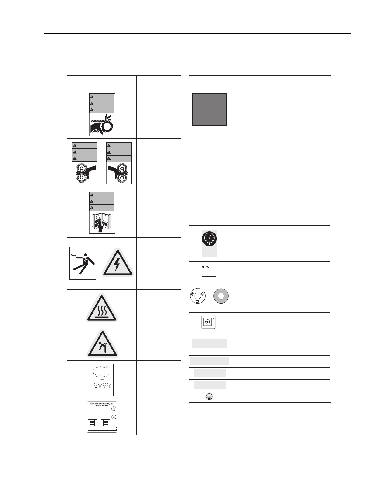
The following are typical safety hazard decals used on GBC Pro-Tech machines, with a brief description (“Meaning” column) of each decal.
Decal Meaning Decal Meaning
WARNING
ACHTUNG
MISE EN GARDE
©1994 Hazard Communication Systems, Inc. 800-748-0241
WARNING
ACHTUNG
MISE EN GARDE
or
WARNING
ACHTUNG
MISE EN GARDE
or
WARNING
ACHTUNG
MISE EN GARDE
WARNING!
Moving parts can
crush and cut.
Do not operate with
guard or door open.
WARNING!
Crush and burn
hazard. Stay clear of
moving rollers. Stop
machine and raise roll
before cleaning.
WARNING!
Carefully read
Operator's Manual
before handling this
machine. Observe
instructions and safety
rules when operating.
WARNING!
HAZARDOUS
VOLTAGE.
To be serviced only by
trained and authorized
personnel.
Lockout power before
servicing.
CAUTION!
Surface is hot.
A burn hazard exists.
SAFETY
INSTRUCTIONS
SICHERHEITSRICHTLINIEN
CONSIGNES DE
SÉCURITÉ
≤ 100 PSI
≥ 700 KPa
©1997 HCS, Inc. 800-748-0241 No. 6101-52BVPK
C
N
E
G
R
E
M
E
or
S
U
A
T
WARNING!
1. Read and understand the Operation Manual and
all safety labels before operating this machine.
2. Only a trained person is to be permitted to operate
this machine. Training should include instruction
in operation under normal conditions and
emergency situations.
3. This machine is to be serviced only by trained and
authorized personnel. Follow lockout procedures
before servicing.
4. Never reach into the machine for any reason unless
the machine is at a COMPLETE STOP.
5. Never leave the machine stopped in such a manner
that another worker can start the machine while
you are working on or within the machine.
6. Never change or defeat the function of electrical
interlocks or other machine "shutdown" switches.
7. Before starting this machine, check that:
- All persons are clear of the machine.
- No maintenance work is being performed on
the machine.
- All guards are in place.
- All parent rolls are well chucked in the unwind
stands.
- The machine is free of paper scraps, wraps and
jams.
8. There is a potential hazard of entanglement in this
machine caused by items such as long hair, loose
clothing, and jewelry. Make sure your clothing and
hair fit closely to your body and that all jewelry,
rings and watches are removed.
CAUTION!
Air pressure must be less than 100 PSI (700 kPa) to
avoid damaging the machine.
Reset.
S
T
O
Y
P
A
R
R
E
T
D
'
U
R
G
E
N
C
Press this button to stop the machine cycle, remove
O
E
N
electric power, and separate (open) rolls to eliminate a
pinch point (on some machines).
WARNING!
EMERGENCY STOP BUTTON
Electric power disconnect and lock out location.
CAUTION!
Rolls are heavy.
Use proper lifting
techniques to prevent
injury.
CAUTION!
For continued
6 A 1 A 6 A
24VDC
6 A/250V 1/4 X 1-1/4 IN [ 5 X 20mm ]
1 A/250V 1/4 X 1-1/4 IN [ 5 X 20mm ]
CAUTION
FOR CONTINUED PROTECTION AGAINST RISK OF FIRE,
REPLACE ONLY WITH SAME TYPE AND RATING OF FUSE
®
VAC
Hz
Amps
Phase
Wires
MADE IN U.S.A.
LISTED
I.T.E
6N10
®
Model No. Serial No.
protection against risk
of fire, replace only with
same type and rating
of fuse.
Machine identification
label.
CAUTION! EXPOSED ROLLER
Can cause personal injury.
Keep hands, long hair, ties, jewelry
and loose clothing away from this area.
Emergency Stop Kick Cables Located Below.
Kick or Step on to Stop Laminating Process.
SEE INSTALLATION INSTRUCTIONS
BEFORE CONNECTING TO THE
SUPPLY
HIGH LEAKAGE CURRENT!
Earth connection essential before
connecting supply
CAUTION!
Can cause personal injury. K eep hands, long hair, ties,
jewelry and loose clothing away from this area.
Emergency Stop Kick Cables Located Below. Kick or
SEE INSTALLATION INSTRUCTIONS BEFORE
Earth connection essential before connecting supply.
EXPOSED ROLLER
Step on to Stop Laminating Process.
CONNECTING TO THE SUPPLY .
HIGH LEAKAGE CURRENT!
Earth ground.
Page 12

Safety
ORCA-IV Image Transfer Laminator Operation Manual
1-8
© GBC Pro-Tech 1998 October
Blank page.
Page 13
ORCA-IV Image Transfer Laminator Operation Manual
Installation
© GBC Pro-Tech 1998 October
2-1
6HFWLRQ,QVWDOODWLRQ
IMPORTANT
IMPORTANT
IMPORTANT
Note
CAUTION
GBC Pro-Tech is committed to a program of ongoing
product improvement. As a result, we are providing
these instructions so that you can ensure that your new
ORCA-IV Laminator is properly and securely
unpacked, moved and installed.
Before an ORCA-IV Image Transfer Laminato r ca n be
installed there are a few requ irement s that must be met.
Make certain that each of th e req uiremen ts lis ted in the
following preinstallation checklist are met before
beginning installation.
Failure to follow the pr einst allat ion chec klist can
result in damage to the image transfer laminator.
The operating environment must be free of dust,
flammable liquids and vapors. You can be
injured by inhaling c hemical vapors. Vapor build
up or stored flammable liquids can cause a fire.
Excessive dust can damage the image transfer
laminator.
Do not locate the image transf er laminator wher e
air is blowing directly on the machine. The air
flow can cool the rol ls unevenly and r esult in po or
quality output.
3UHLQVWDOODWLRQ&KHFNOLVW
❏ Are doorways and hallways wide enough for the
image transfer laminator to be moved to the installation site?
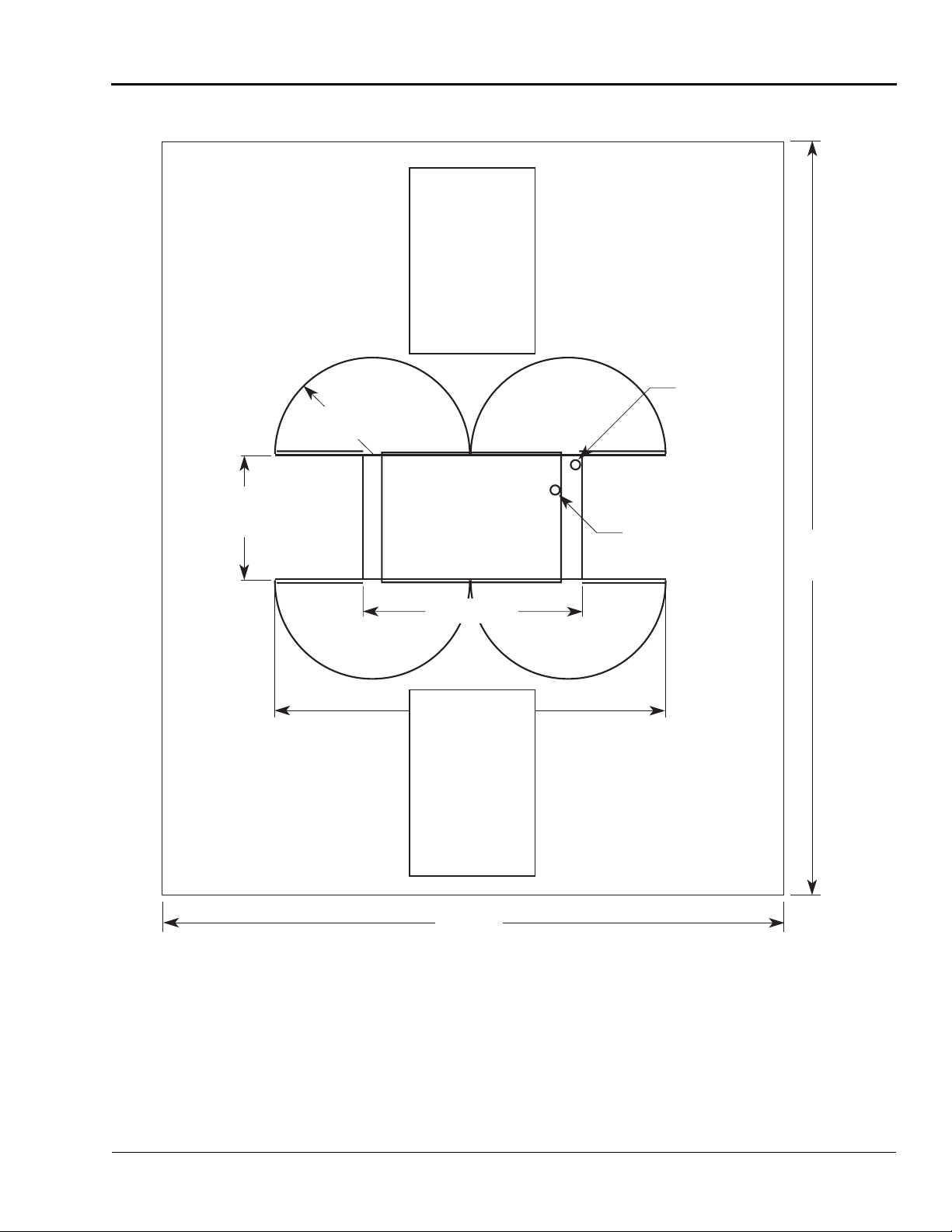
❏ Is there ample room for the image transfer lamina-
tor?
A work area must be established that allows for
operation in both the front and the rear of the
machine and provides space for efficient material
flow. See Figure 2-6: Machine Space Require-
ments for a typical machine area layout.
❏ Is the environment appropriate for the image trans-
fer laminato r?
The image transfer laminator requir es a clean, dust
and vapor free environment to operate properly,
such as an air conditioned office area with forced
10% make up air . However, the image transfer laminator must not be located where there is air blowing directly on it. Major fluctuation in temperature
and humidity are to be avoided.
❏ Have you contacted a certified electrician to both
hard wire the laminator and ensure that an adequate
power supply, having the appropriate capacity,
overcurrent protect ion, and saf ety loc kouts i s available?
The laminator requires 4 wire North American
Delta 230 VAC, 50/60 Hz, three phase, 45A per
phase with the preheater option and 35A per phase
without the preheater option.
☞
If you require setup for European power input (three
phase wye), please contact GBC Technical Support.
Do not ever attempt to change the internal
jumper configurations. Only a qualified GBC
Service Technician can change these
configurations. You can severely damage the
machine.
Page 14

Installation
ORCA-IV Image Transfer Laminator Operation Manual
2-2
© GBC Pro-Tech 1998 October
❏ Is there an appropriate filtered dry air supply avail-
IMPORTANT
able?
The machine requires filtered dry air at 1.5 cubic
feet per minute (cfm), 50 liter s/minute at a pre ssure
of 100 pounds per square inch (psi) (700 kPa). The
air supply must be clean (free of dirt) and dry.
Moisture causes corrosion and particles block
pneumatic controls. Either problem can cause the
laminator to ma lfunction.
It is the customer's responsibility to provide appropriate filters and water trap s for the air hose before
the air is routed to the la minator . Pro-T e ch suggests
that the best approach to the air requirement is to
provide a dedicated small compressor for the laminator. A standard l igh t- duty ½ to ¾ horse power ( 1
kW) electric air compressor with 1.5 to 2.5 cfm
output with a 5 gallon (20 liter) storage tank is
appropriate.
The air supply to the laminator must be clean
and dry or the machine will be damaged.
Page 15
ORCA-IV Image Transfer Laminator Operation Manual
Installation
© GBC Pro-Tech 1998 October
2-3
4' x 6'
(1.2m x 2m)
Work Table
on Wheels
50"
(1.27m)
38.4"
(.98m)
Rear
85" (2.16m)
Front
153" (3.89m)
4' x 6'
(1.2m x 2m)
Work Table
on Wheels
Electrical
Supply
(Standard
Inlet on
Bottom of
Machine)
Air Supply
(On Bottom of
Machine)
24'
(7.3m)
20' (6m)
Figure 2-6: Machine Space Requirements
Page 16
Installation
ORCA-IV Image Transfer Laminator Operation Manual
2-4
© GBC Pro-Tech 1998 October
8QSDFNLQJ
NOTE
IMPORTANT
IMPORTANT
IMPORTANT
☞
ALL SHIPMENTS ARE EX- WORKS. At our dock title
passes to the buyer Please review your insurance coverage prior to shipment, as you are responsible for all
subsequent freight charges and risks. Before signing
the Bill of Lading you should be sure to inspect the
machine for signs of damage or missing items; if applicable, you should make a note o f thi s on t he Bil l of Lading.
The ORCA-IV Image Transfer Laminator is shipped
encased in shrink wrap via Air Ride Van.
To unpack the machine:
7. Have the image transfer laminator rolled off the
Air Ride Van and placed on the floor by licensed
riggers.
Do not attempt to move the image transfer
laminator across anythi ng other than a fla t, level
surface without trained and qualified riggers.
You can be crushed or seriously injured.
The ORCA-IV Image Transfer Laminator is a
large and heavy piece of equipment. It is
necessary to employ LICENSED RIGGERS
ONLY to move the machine. The image transfer
laminator is not designed to be tipped up or
sideways in any way. Such action disturbs the
exact alignment of the rolling parts of the
machine and requires extensive realignment.
GBC Pro-Tech’s warranty does not cover
malfunction of the equipment due to mis handling
and/or tipping.
GBC Pro-Tech bears no responsibility for
personal injury or damage due to moving the
image transfer laminator improperly.
8. Gently unwrap the shrink wrap from around the
image transfer laminator and remove the foam protecting the corners of the machine.
Do not use a knife or other sharp instrument
during installation or while servicing the image
transfer laminator. You can cause irreparable
damage to the rolls.
9. Carefull y remove any accessories pac ked with the
machine. The accessory pack should contain:
1 Towel, white
1 Slitting knife
1 Set, hex wrenches
4 Leveling pads
3 Fuses (6A, 250V)
1 Tape measure
1 Rubber cement pick-up
1 Strain relief
1 Manual
4 Slitter Assemblies
2 T-handle wrenches (
2 Web unwind spacers
10. Remove any plastic strapping and packing paper
taped to the
Do not use a knife or other sharp instrument
during installation or while servicing the image
transfer laminator. You can cause irreparable
11. Remove all packing materials to a safe distance
from the imag e transfer lamin ator.
roll
s.
damage to the rolls.
1
/4")
12. Level the machine using the procedure included in
this section.
Page 17
ORCA-IV Image Transfer Laminator Operation Manual
Installation
© GBC Pro-Tech 1998 October
2-5
☞
NOTE
A word about international shipments: As these are
heavy pieces of equipment, GBC Pro-Tech takes every
precaution to ensure that our image transfer laminators are properly crated to the highest standards.
Before machines leave our loading dock, they are pretreated with a VCI protective film to provide total corrosion protection. This protective film is wrapped
around t he machi ne and comp letel y seal ed. In a dditi on,
moisture absorbing silicone desiccant packs are
packed inside the crate and machine cabinets.
Prior to sta rt up of the machi ne, you must remove the
desiccant packs from each cabinet and discard. DO
NOT operate the machine with the desiccant packs
inside the cabinets.
6HWXS
Once the ORCA-IV Image Transfer Laminator has
been unpacked and moved into final position perform
the following setup procedure.
/HYHOLQJ
Tools required:
• Adjustable wrench
• Carpenter's level (or equivalent)
To level the laminator :
1. Install the four level pads (included in the accessory pack) on the ends of the foot bolts.
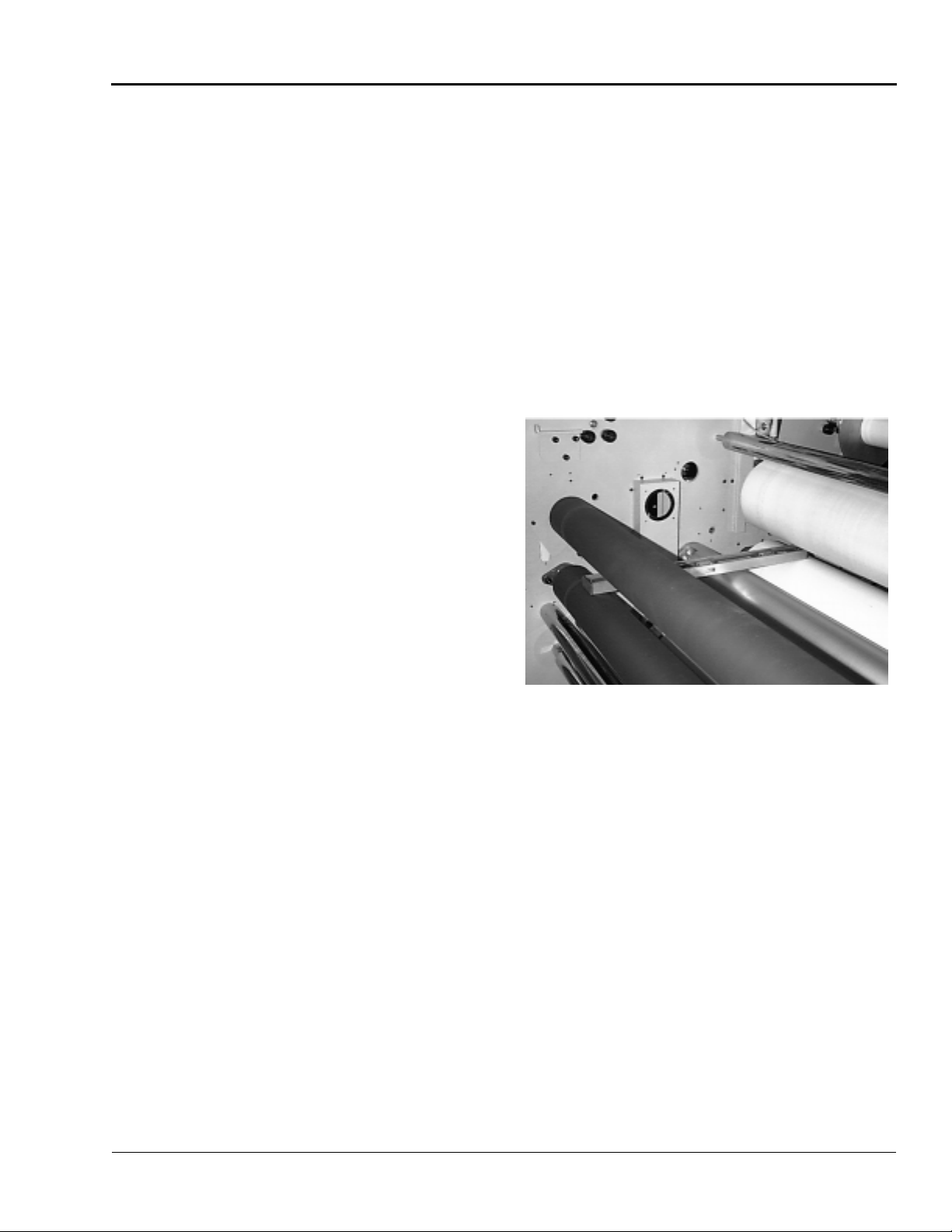
2. Remove the rear idler so that you can place a carpetner’s level across the pull roll to the bottom
main roll.
Tools required:
1
•
/8" hex wrench
• Adjustable wrench
Setup Procedure
1. Inspect the machine for any obvious shipping damage.
2. Remove the drive and control side cabinet covers
with the
securing th e covers to the machine. Lift the covers
off.
3. Inspect all the bolts and tighten any that were loosened during shipping.
4. Have a certified electrician wire the machine
directly to a power source.
5. Connect the machine to the air supply.
6. Replace all cabinet covers.
1
/8" hex wrench by removing the screws
Figure 2-7: Leveling Front to Rear
3. Level thi s side of the machine front to rear, raising
or lowering the leveling pads by adjusting the nuts
on the foot bolts.
4. Move the level to the other s ide of the machine and
level front to rear.
5. Place the level directly on the chrome tie bar below
the pull rolls and level the back of th e machine s ide
to side.
Page 18

Installation
ORCA-IV Image Transfer Laminator Operation Manual
2-6
© GBC Pro-Tech 1998 October
Figure 2-8: Leveling Side to Side
IMPORTANT
IMPORTANT
6. Place the level di r ectly on the chro me tie bar in the
front of the machine and level the front of the
machine side to side.
7. Recheck the front to rear level condition to ensure
that it has not changed. I f it has, r epeat t he leve ling
procedure.
8. Remove the four metal casters after the machine is
leveled (casters provided for transportation only).
6WDUWXS
The first time the image transfer laminator is started
and every time it is serviced you should use the following checklist to confirm that the unit is op erating properly and that all safety mechanisms are functioning.
Startup Checklist
Start the image transfer laminator and go through the
following checklist.
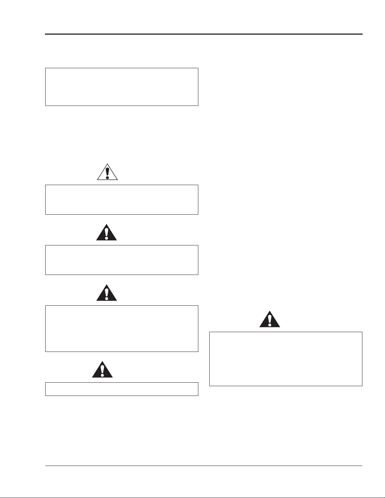
❏ Are the emergency stop buttons working?
Push down on one of the emergency stop buttons.
The image transfer laminator should stop immediately. Reset the button by turni ng it c lockwis e un til
it pops up. Press the reset button. See
Machine Reset Button
reset button. Start the laminator. The machine
should resume operation. Always check all four
buttons.
Never operate the image transfer laminator
unless all of the emergency stop buttons are
functioning properly. You can be crushed or
to locate the main machine
burned.
Figure 1-4:
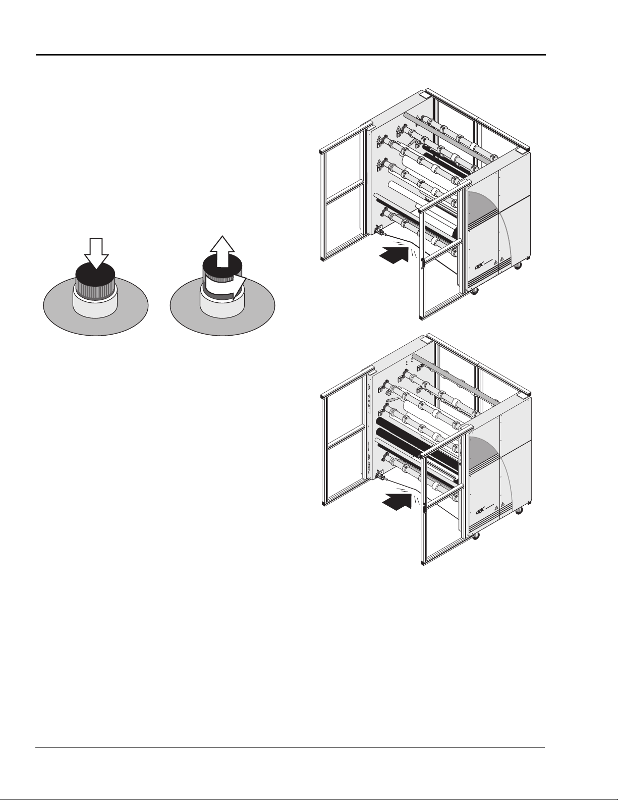
❏ Are the emergency stop kick cables working?
With the laminator running, step on or kick the
front emergency stop kick cable. The rolls should
stop turning and ris e, if the y are lo were d. Reset t he
kick cable button. See
Reset Button
Then reset the main mach ine reset . See
Machine Reset Button
reset button.
Never operate the image transfer laminator
unless both of the emerg ency st op kick c ables a r e
functioning properly. You can be crushed or
to locate the kick cable reset button.
Figure 1-3: Kick Cable
Figure 1-4:
to locate the main machine
burned.
Page 19

ORCA-IV Image Transfer Laminator Operation Manual
Installation
© GBC Pro-Tech 1998 October
2-7
❏ Is the safety system on the doors functioning.
Note
IMPORTANT
IMPORTANT
CAUTION
Open any door of the image tran sfer lamina tor . The
rolls should slow to 3.0 ft/min (1 m/min) with the
doors open. You should not be able to increase the
speed of the machine above 3.0 ft/min (1 m/min).
☞
The speed control works best with a slow, gradual
increase or decrease of the speed control knob.
Never operate the image transfer laminator
unless safety system on the doors is functioning
properly. You can be crushed or burned.
❏ Is the motor functioning?
Test the motor at various speeds ranging from
0-19 ft/min (0-5.8 m/min). At 0 the
stop turning.
Run the motor in both forward and reverse. In
reverse you should hear a beep once a second to
alert you that you are operating the machine in
reverse.
roll
s should
Never allow loose objects (pens, knife blades,
jewelry, etc.) close to the machine or web paths.
These objects can fall onto the web and can be
carried through to the roll. Severe roll damage
can occur.
Once you have completed the s tartup ch eck list you can
safely run a test sample.
❏ Are the heaters working?
Verify that the heater controller heats the top roll.
(The bottom roll cannot be heated.)
❏ Is the temperature set correctly?
Check that the temperat ure is set to 290°F
(143.3 °C) for most transfer processes.
Never allow any film, packing material, object,
etc. to block the infrar ed tem perature sensor. The
sensor has a cone-shaped view of the roll that
should never be obstructed. Severe roll damage
can occur.
Page 20

Installation
ORCA-IV Image Transfer Laminator Operation Manual
2-8
© GBC Pro-Tech 1998 October
Blank page.
Page 21

ORCA-IV Image Transfer Laminator Operation Manual
Operation
© GBC Pro-Tech 1998 October
3-1
6HFWLRQ2SHUDWLRQ
Note
WARNING
6DIHW\
The ORCA-IV Image Transfer Laminator has been
designed with safety as a primary consideration. However, you must become thoroughly familiar with the
controls, proper operation, proper service procedures,
and safety features of the image transfer laminator
before using or servicing the unit.
Do not ever attempt t o overr ide the safet y syst em
on the doors of the machine or the kick cables.
You could get your fingers or arms between the
rolls when they are turning or in the closed
position and you could be crushed or severely
burned.
The GBC Pro-Tech ORCA-IV is a powerful machine
that is designed for vinyl transfer and over-lamination.
The forces required to accomplish these tasks are very
large.
The air-cylinder system used to provide downward
pressure on the top roll is capable of producing forces
greater than 1000 pounds (454kg). This fo rce is appli ed
to any object presented in the opening (called the nip)
between the two rolls.
Use care in lowering the t op main roll and know h ow to
react quickly in an emergency. The laminator roll UP-
DOWN switch is located on the instrument panels.
This switch controls the up and down motion of the top
laminator roll. Before pres sing this switch to the
DOWN position, ensure tha t no thi ng i s i n t he n ip a re a.
If any problem or danger should occur, depressing any
of the emergency buttons stops the rolls from closing
and raises them completely.
☞
To quickly stop the machine in the event of an emergency , press any of the emergency stop b uttons or appl y
force t o eith er kic k cab le. This actio n st ops the mac hine
completely and raises the rolls.
The machine has a steel cabine t th at is bol te d closed to
isolate the electrical and drive system components for
the safety of the operato r. Only a qualified service technician should open these cabinets.
In addition, the rolls of the ORCA-IV can reach temperatures of over 290 °F (143 °C). At these temperatures there is a danger of a severe burn if the rolls are
touched during set-up, operation or servicing.
Opening any door of the image transfer laminator
causes the rolls to slow to 3.0 ft/min (1 m/min).
Page 22

Operation
ORCA-IV Image Transfer Laminator Operation Manual
3-2
© GBC Pro-Tech 1998 October
The machine is equipped with four emergency stop
buttons located on either side of the front and back of
the image transfer laminator. Any of these, if engaged,
stops the machine. To continue operation, all emergency stop buttons must be in the up position and you
must perform the Machine Reset Procedure. See
“Machine Reset Procedure” on page 3-3.
Push any button
to stop the
laminator
Twist each button
to resume
operation - the
button pops out
FRONT
N
E
C
Y
G
S
T
R
O
E
P
M
E
A
R
R
S
E
U
T
A
D
T
O
'
U
N
R
G
E
C
E
N
%
100
90
80
70
60
50
40
30
20
10
%
100
90
80
70
60
50
40
30
20
10
%
100
90
80
70
60
50
40
30
20
10
%
100
90
80
70
60
50
40
30
20
10
P
R
O
-
T
E
C
H
W
A
RN
ING
ACH
TUN
M
IS
G
E
E
N
G
A
R
D
E
Carefully read Operator's
Manual before handling
this machine. Observe
instructions and safety
rules when operating.
©
1
9
9
4
H
C
S
,
In
c
.
8
0
0
-
7
4
8
-
0
2
4
1
R
e
o
r
d
e
r
N
o
.
6
0
0
1
P
T
N
E
C
Y
G
S
T
R
O
E
P
M
E
A
R
R
S
E
U
T
A
D
T
O
'
U
N
R
G
E
C
E
N
psi
100
kPa
90
700
80
630
70
560
60
490
50
420
40
350
30
CAL 3200
280
20
210
10
140
70
CAL 3200
4
0
0
0
0
12
34
ORCA IV™
A
U
S
NOT
E
C
N
E
G
R
U
'
D
T
E
R
R
E
M
E
R
G
E
N
C
Y
S
T
OP
A
E
C
N
E
G
R
U
'
A
U
S
NOT
1
/
4
D
T
E
R
R
E
M
n
r
u
t
A
OP
E
R
G
E
N
C
Y
S
T
Figure 3-1: Using the Emergency Stop Buttons
In addition, the ORCA-IV is equipped with two emergency stop kick cables located at the lower front and
back of the image transfer laminator.
BACK
Emergency
Stop Kick
Cable
N
C
E
Y
G
S
R
T
O
E
P
M
E
A
R
R
S
E
U
T
A
D
T
O
'
U
N
R
G
E
C
E
N
%
1
0
0
9
0
8
0
7
0
6
0
5
0
4
0
3
0
2
0
1
0
%
1
0
0
9
0
8
0
7
0
6
0
5
0
4
0
3
0
2
0
1
0
%
1
0
0
9
0
8
0
7
0
6
0
5
0
4
0
3
0
2
0
1
0
P
R
O
-T
E
C
H
WARNING
ACHTUNG
MISE EN GARDE
Carefully read Operator's
Manual before handling
this machine. Observe
instructions and safety
rules when operating.
©
1
9
9
4
H
C
S
,
I
n
c
.
8
0
0
-
7
4
8
-
0
2
4
1
R
e
o
r
d
e
r
N
o
.
6
0
0
1
-
P
T
P
O
W
E
R
Emergency
Stop Kick
Cable
PRO-TECH
N
C
E
Y
G
S
R
T
O
E
P
M
E
A
R
R
S
E
U
T
A
D
T
O
'
U
N
R
G
E
C
E
N
psi
100
kPa
90
7
80
00
6
70
30
560
60
490
50
420
40
psi
350
30
100
280
20
kP
90
210
10
a
700
80
140
630
70
70
560
6
0
490
50
420
40
350
30
280
20
210
10
140
70
P
R
O
-
T
E
C
H
0
0
00
1
2
3
4
ORCA IV™
PRO-TECH
Figure 3-2: Using the Emergency Stop Kick
Cables
Either of these, if stepped on or kicked, stops the laminator and raises the rolls. To continue operation, press
the kick cable reset button. Then compl ete the Machine
Reset Procedure. See “Machine Reset Procedure” on
page 3-3.
Page 23

ORCA-IV Image Transfer Laminator Operation Manual
Operation
© GBC Pro-Tech 1998 October
3-3
Kick Cable
g
Reset Button
Figure 3-3: Kick Cable Reset Button
Machine Reset Procedur e
6. Start the motor and increase the speed.
N
E
C
Y
G
S
T
R
O
E
P
M
E
A
R
R
S
E
U
T
A
D
T
O
'
U
N
R
G
E
C
E
N
%
1
0
0
9
0
8
0
7
0
6
0
5
0
4
0
3
0
2
0
1
0
%
1
0
0
9
0
8
0
7
0
6
0
5
0
4
0
3
0
2
0
1
0
%
1
0
0
9
0
8
0
7
0
6
0
5
0
4
0
3
0
2
0
1
0
PRO-TECH
Reset
Power
Switch
w/ Lock
Button
Perform this procedure whenever an emergency stop
button or kick cable is activated or when the power to
the machine is turned on.
1. Make sure all emergency stop buttons and kick
cables are reset.
2. Press the main machine reset button above the
power switch on the back of the machine. See
ure 3-4: Machine Reset Button
.
Fig-
3. Check the web force se ttings to make sure they are
what you require.
4. Restart the heater if it is being used.
5. Lock the shafts by closin g the doors of the machine
and pressing the shaft lock button or starting the
motor.
WARNING
ACHTUNG
Power
MISE EN GARDE
Switch/
Lockout
POWER
Figure 3-4: Machine Reset Button
$XGLEOH 6LJQDOV
For your safety, the machine has several audible si gnals
that are used to alert you to the status of the machine.
The following table lists the alert signals.
Table 3-1: Audible Signals
Audible Signal Meanin
Continuous rapid beep If the roll is down but
not turning, the machine
will begin beeping continuously after 10 seconds.
Four beeps every 30 seconds after 55 minutes of
inactivity
If the roll is up and the
heater is on, the machine
will begin beeping four
times every 30 seconds
after the machine has
been inactive for 55
minutes.
One beep per second The machine is in
reverse.
Page 24

Operation
ORCA-IV Image Transfer Laminator Operation Manual
3-4
© GBC Pro-Tech 1998 October
2SHUDWRU&RQWUROV
a
a
The operator controls for the ORCA-IV Image T ransfer
Laminator are located on the front and rear of the
machine, to th e right of the operator positions. The
names and functions of these controls are as follows:
)URQW &RQWURO 3DQHO
psi
kPa
100
700
90
630
80
560
70
490
1
60
420
Main Roll
Pressure
Display
Main Roll
UP/DOWN
Main Roll
Pressure
Adjustment
Preheater
ON/OFF
(optional)
GBC Logo
Automatic/Manual
Mode Control
Speed/
Accumulator
Display
Speed
Adjustment
2
3
4
5
6
7
CAL 3200
50
350
40
280
30
210
20
140
10
70
CAL 3200
PRO-TECH
0000
Figure 3-5: Front Control Panel
1. MAIN ROLL PRESSURE DISPLAY - Displays
the air pressure pushing the upper main roll down.
2. MAIN ROLL UP/DOWN - Sets the upper main
roll to the up (load) or down (operate) position.
3. MAIN ROLL PRESSURE CONTROL - Varies
the air pressure fed to the cylinders that drive the
upper main roll down.
4. PREHEATER ON/OFF (optional) - Turns on or
off the preheater. The preheater mode is indicated
by a P in the accumulator display.
5. GBC LOGO AUTOMATIC/MANUAL MODE
CONTROL - T oggles bet ween Automatic T en sion
and Manual Tension mode. In Automatic Tension
mode, the system automatically adjusts the brake/
clutch pressure. In Manual Tension mode the system doesn’t automatically adjust these pressures
(indicated by an H or L in the accumulator display). In the Automatic Tension mode with the
motor stopped, setting a web force (tension) for
1234
Roll Temperature
8
Adjustment/Displ
9
Roll Heat
ON/OFF
10
Pull Roll
UP/DOWN
11
Cooling Fan
ON/OFF
Preheater
12
Temperature
Adjustment/Displ
(optional)
13
Preheater Heat
ON/OFF
14
Accumulator
Reset
15
Speed/
Accumulator
Toggle
16
Motion Control
FORWARD/
STOP/REVERSE
either a clutch or brake loads that force into the
internal computer, which then automatically
adjusts the air pressure sent to the clutch/brake to
obtain the required web tension based on the roll
size. When you enter the setting and then turn the
motor on, the indicator changes from reading the
web force to the actual pressure sent to the br ake to
attain the requi red web forc e calculated for that rol l
size. In Manual Tension mode the display reads
actual pressure sent to the clutch/brake. This pressure stays set until you change it. The computer
will not override you r sett ing or ch ange the dis play.
6. SPEED/ACCUMULATOR DISPLAY - Dis-
plays either the accumulator or speed, depending
on which you have selected with the SPEED/
ACCUMULATOR TOGGLE. A letter in the display before the spe ed readout indi cates the mode o f
operation:
H - Manual mode with the preheater off.
P - Automatic mode with the preheater on.
L - Manual mode with the preheater on.
No letter - Au tomatic mode with the preheater off.
The following codes alert you to machine status:
.0 - The machine is reset and ready to be started.
8888 - Main power has ju st bee n turned on and the
main reset has not yet been pressed.
In addition to these codes, if an emergency stop
button or kick cable is activated, the decimal point
will no longer be displayed ( for example ,
change to
3 0
). Simply r esetting the emer gency st op
3.0
would
button or kick cable does not change the display.
You must also press the main machine reset button
for display to read .0 indicating the machine is
ready to be started. Note that you must reset the
emergency stop button or kick cable
before
pressing the main machine reset or the machi ne will not
be reset.
7. SPEED ADJUSTMENT - Adjusts the speed of
the machine from zero to max imum as the control
is turned clockwise. Adjust the speed control
slowly for best results.
Page 25

ORCA-IV Image Transfer Laminator Operation Manual
Operation
© GBC Pro-Tech 1998 October
3-5
8. ROLL TEMPERATURE - Provides a readout of
the temperature of the upper main roll and the setpoint for the desired t emperat ure adj ustment . Press
the star button on the temperature controller to see
or change the set point.
9. ROLL HEAT ON/OFF - Turns the heater contr ol-
ler for the top roll on or off.
10. PULL ROLL UP/DOWN - Sets the pull roll to
the up (load ) or down (op erate) position.
11. COOLING FAN ON/OFF - Turn s the cooli ng fan
on or off. Push once to turn only the cooling idlers
on, push again to turn only the cooling tubes on,
push a third time to turn both cooling idlers and
cooling tubes on, and push a fourth time for all
cooling off.
12. PREHEATER AIR TEMPERATURE
(optional) - Provides a readout of the temperature
of the air inside the preheater and the set-point for
the desired temperature.
13. PREHEA TER HEA T ON/OFF - T urns the heat er
controller in the prehe ater roll on or off.
14. ACCUMULATOR RESET - Resets the accumu-
lator.
15. SPEED/ACCUMULATOR TOGGLE - Toggles
control between the speed and the accumulator.
16. MOTION CONTROL FORWARD/STOP/
REVERSE - Controls the direction of the drive
system, forward, reverse, or stop.
Page 26

Operation
ORCA-IV Image Transfer Laminator Operation Manual
3-6
© GBC Pro-Tech 1998 October
)URQW &OXWFK%UDNH 3DQHO
h
c
h
h
e
%
100
90
Upper Middle
Clutch (Rewind)
Percent Web
Force
Upper Front
Clutch (Rewind)
Percent Web
Force
Middle Front Brake
Percent Web Force
Unwind/Rewind Shaft
Locking System ON/OFF
Lowerr Front Brake
Percent Braking
Force
80
70
1
60
50
40
30
20
10
%
100
90
80
70
4
60
50
40
30
20
10
%
100
90
80
70
7
60
50
40
30
20
10
%
100
90
80
10
70
60
50
40
30
20
11
10
PRO-TECH
2
Upper Middle Clut
(Rewind) Pressure
3
Upper Middle Clutc
(Rewind) Indicator
5
Upper Front Clutc
(Rewind) Pressure
6
Upper Front Clutc
(Rewind) Indicator
8
Middle Front Brak
Pressure
9
Middle Front
Brake Indicator
12
Lower Front Brake
Pressure
13
Lower Front Brake
Indicator
Figure 3-6: Front Brake Panel
1. UPPER MIDDLE CLUTCH (REWIND) PERCENT WEB FORCE - Indicates the web force
(tension) for this clutch as a percentag e of the t o t al
possible tension the clutch can exert. What the
pressure indicator displays will change depending
upon whether the motor i s on or of f and wha t mode
you are operating the machine under. With the
motor direction arrows off and the machine in
Automatic T ension mode, the indic ator displays th e
material web tension you set. Once the motor
arrow is pressed and the machine starts, the computer calculates the appropriate pressure to attain
the required web force based on the roll size. The
indicator then changes to read the actual air pressure (in psi) sent t o the c lutch /brake. If the machine
is in Manual Tension mode, the indicator reads the
actual air pressure (in psi) sent to the clutch/brake.
2. UPPER MIDDLE CLUTCH (REWIND) PRES-
SURE - Adjusts the clutch pressure up or down.
3. UPPER MIDDLE CLUTCH (REWIND) INDI-
CATOR - Indicates that th is set of controls is for
the upper middle clutch.
4. UPPER FRONT CLUTCH (REWIND) PER-
CENT WEB FORCE - Indicates the web force
(tension) for this clutch as a percentag e of the t o t al
possible tension the clutch can exert. What the
pressure indicator displays changes depending
upon whether the motor i s on or of f and wha t mode
you are operating the machine under. With the
motor direction arrows off and the machine in
Automatic T ension mode, the indic ator displays th e
material web tension you set. Once the motor
arrow is pressed and the machine starts, the computer calculates the appropriate pressure to attain
the required web force based on the roll size. The
indicator then changes to read the actual air pressure (in psi) sent to the clutch/brake. If the machine
is in Manual Tension mode, the indicator reads the
actual air pressure (in psi) sent to the clutch/brake.
5. UPPER FRONT CLUTCH (REWIND) PRES-
SURE - Adjusts the clutch pressure up or down.
6. UPPER FRONT CLUTCH (REWIND) INDI-
CATOR - Indicates that th is set of controls is for
the upper front clutch.
7. MIDDLE FRONT BRAKE PERCENT WEB
FORCE -Indicates the web fo rce (tension) for thi s
brake as a percentage of the total possible tension
the brake can exert. What the pressure indicator
displays changes depending upon whether the
motor is on or of f a nd what mode you are oper ating
the machine under. With the motor direction
arrows off and the machine in Au tomatic Tension
mode, the indicator displays the material web tension you set. Once the motor arrow is pressed and
the machine starts, the computer calculates the
appropriate pressure to attain the required web
force based on the roll size. The indicator then
changes to read the actual air pressure (in psi) sent
to the clutch/brake. If the machine is in Manual
Tension mode, the indicator reads the actual air
pressure (in psi) sent to the clutch/brake.
8. MIDDLE FRONT BRAKE PRESSURE Adjusts the brake pressure up or down.
9. MIDDLE FRONT BRAKE INDICATOR - Indi-
cates that this set of cont rols is for the middl e front
brake.
10. UNWIND/REWIND SHAFT LOCKING SYS-
TEM ON/OFF - Engages/disengages the unwind/
rewind shaft locking system. The switch disengages the locking system with the door eit her ope n
or closed with the motor off. The doors must be
shut to engage the sys tem. If the door s are shut a nd
the unwind/rewind shafts are disengaged, pushing
the motion control engages them automatically.
Note the color coding on each shaft and the shaft
loading tray. Unwinds are marked with blue and
rewinds are marked with red. Always use the correct shaft in each loading position.
Page 27

ORCA-IV Image Transfer Laminator Operation Manual
Operation
© GBC Pro-Tech 1998 October
3-7
11. LOW ER FRONT BRAKE PERCENT BRAKING FORCE - Indicat es the web force (tension)
for this brake as a percentage of the total possible
tension the brak e can exert. What the pr essure indicator displays c hanges dependin g upon whether the
motor is on or off and what mode you are operating
the machine under. With the motor direction
arrows off and the machine in Automa tic Tension
mode, the indicator displays the material web tension you set. Once the motor arrow is pressed and
the machine starts, the computer calculates the
appropriate pressure to attain the requi red web
force based on the roll size. The indicator then
changes to read the actual air pressure (in psi) sent
to the clutch/brake. If the machine is in Manual
Tension mode, the indicator reads the actual air
pressure (in psi) sent to the clutch/brak e.
12. LOWER FRONT BRAKE PRESSURE Adjusts the brake pressure up or down.
13. LOWER FRONT BRAKE INDICATOR - Indi-
cates that this set of controls is for the low er front
brake.
Page 28
Operation
ORCA-IV Image Transfer Laminator Operation Manual
3-8
© GBC Pro-Tech 1998 October
5HDU &RQWURO 3DQHO
Pull Roll Torque
7
kPa
700
630
560
490
420
350
280
210
140
70
1234
ON/OFF
Roll Pull Force
8
Adjustment/Display
Pull Roll
9
UP/DOWN
10
Pull Roll Torque
Adjustment
11
Cooling Fan
ON/OFF
12
Accumulator
Reset
13
Speed/
Accumulator
Toggle
14
Motion Control
FORWARD/
STOP/REVERSE
Pull Roll
Pressure
Display
Main Roll
UP/DOWN
Pull Roll
Pressure
Adjustment
GBC Logo
Automatic/Manual
Mode Control
Speed/
Accumulator
Display
Speed
Adjustment
psi
kPa
100
700
90
630
80
560
70
490
1
60
420
50
350
40
280
30
210
20
140
10
70
2
3
4
PRO-TECH
5
6
psi
100
90
80
70
60
50
40
30
20
10
0000
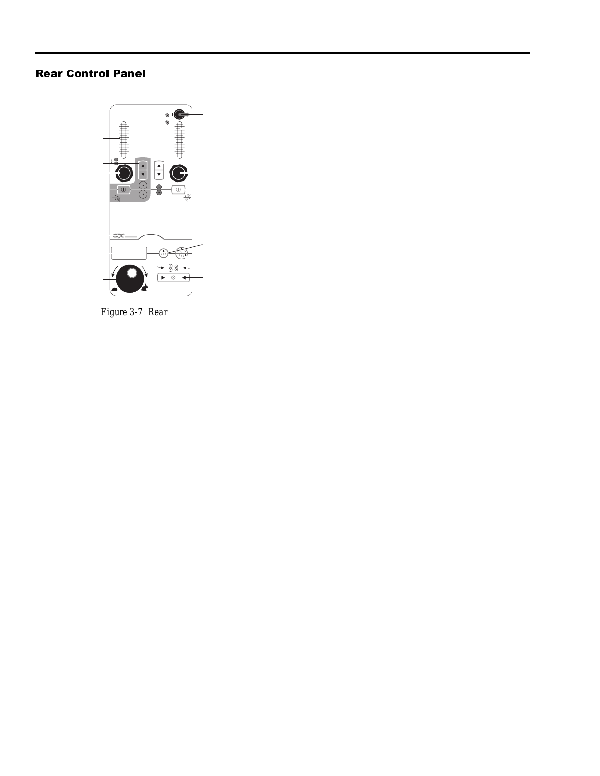
Figure 3-7: Rear Control Panel
1. PULL ROLL PRESSURE DISPLAY - Displays
the air pressure pushing the upper pull roll down.
2. MAIN ROLL UP/DOWN - Sets the upper main
roll to the up (load) or down (operate) position.
3. PULL ROLL PRESSURE CONTROL - Varies
the air pressure fed to the cylinders that drive the
upper pull roll down.
4. GBC LOGO AUTOMATIC/MANUAL MODE
CONTROL -Toggles between Automatic Tension
and Manual Tension mode. In Automatic Tension
mode, the system automatically adjusts the brake/
clutch pressure. In Manual Tension mode the system doesn’t automatically adjust these pressures
(indicated by an H or L in the accumulator display). In the Automatic Tension mode with the
motor stopped, setting a web force (tension) for
either a clutch or brake loads that force into the
internal computer, which then automatically
adjusts the air pressure sent to the clutch/brake to
obtain the required web tension based on the roll
size. When you enter the setting and then turn the
motor on, the indicator changes from reading the
web force to the actual pressure sent to the br ake to
attain the requi red web force ca lculated for that roll
size. In Manual Tension mode the display reads
actual pressure sent to the clutch/brake. This pressure stays set until you change it. The computer
will not override yo ur sett ing or c hang e the dis play.
5. SPEED/ACCUMULATOR DISPLAY - Dis-
plays either the accumulator or speed, depending
on which you have selected with the SPEED/
ACCUMULATOR TOGGLE. A letter in the display before the spe ed readout indi cates the mode o f
operation:
H - Manual mode with the preheater off.
P - Automatic mode with the preheater on.
L - Manual mode with the preheater on.
No letter - Au tomatic mode with the preheater off.
The following codes alert you to machine status:
.0 - The machine is reset and ready to be started.
8888 - Main power has ju st bee n turned on and the
main reset has not yet been pressed.
In addition to these codes, if an emergency stop
button or kick cable is activated, the decimal point
will no longer be displayed ( for example ,
change to
3 0
). Simply r esetting the emer gency st op
3.0
would
button or kick cable does not change the display.
You must also press the main machine reset button
for display to read .0 indicating the machine is
ready to be started. Note that you must reset the
emergency stop button or kick cable
before
pressing the main machine reset or the machi ne will not
be reset.
6. SPEED ADJUSTMENT - Adjusts the speed of
the machine from zero to max imum as the control
is turned clockwise. Turn control knob slowly for
best results.
7. PULL ROLL TORQUE ON/OFF - Allows you
to turn the pull roll clutch (torque) pressure on or
off without changing the pressure settings.
8. PULL ROLL PULL FORCE DISPLAY - Dis-
plays the air pressure of the clutch (torque or pull
force).
9. PULL ROLL UP/DOWN - Sets the pull roll to
the up (load) or down (operate) position.
10. PULL ROLL TORQUE CONTROL - Varies the
air pressure fed to the clutch that drives the lower
pull roll.
11. COOLING FAN ON/OFF - T urns th e cooling f an
on or off. Push once to turn only the cooling idlers
on, push again to turn only the cooling tubes on,
push a third time to turn both cooling idlers and
cooling tubes on, and push a fourth time for all
cooling off.
Page 29

ORCA-IV Image Transfer Laminator Operation Manual
Operation
© GBC Pro-Tech 1998 October
3-9
12. ACCUMULATOR RESET - Resets the accumu-
lator.
13. SPEED/ACCUMULATOR TOGGLE - Toggles
control between the speed and the accumulator.
14. MOTION CONTROL FORWARD/STOP/
REVERSE - Controls the direction of the drive
system, forward, reverse, or stop.
Page 30

Operation
ORCA-IV Image Transfer Laminator Operation Manual
3-10
© GBC Pro-Tech 1998 October
5HDU &OXWFK%UDNH 3DQHO
%
100
90
80
70
1
60
Upper Rear Brake
Percent Web Force
Middle Rear Clutch
Percent Web Force
Lower Rear Clutch
Percent Web Force
Unwind/Rewind
Shaft Locking
System ON/OFF
50
40
30
20
10
%
100
90
80
70
4
60
50
40
30
20
10
%
100
90
80
70
7
60
50
40
30
20
10
10
PRO-TECH
2
Upper Rear Brake
Pressure
3
Upper Rear Brake
Indicator
5
Middle Rear Clutch
Pressure
6
Middle Rear
Clutch Indicator
8
Lower Rear Clutch
Pressure
9
Lower Rear Clutch
Indicator
appropriate pressure to attain the required web
force based on the roll size. The indicator then
changes to read the actual air pressure (in psi) sent
to the clutch/brake. If the machine is in Manual
Tension mode, the indicator reads the actual air
pressure (in psi) sent to the clutch/brake. Note that
this clutch (laminate paper rewind) only operates
when the pull roll is down.
5. MIDDLE REAR CLUTCH PRESSURE -
Adjusts the clutch pressure up or down.
6. MIDDLE REAR CLUTCH INDICA TOR - Indi-
cates that this set of cont rols is for th e middle rear
clutch.
Figure 3-8: Rear Brake Panel
1. UPPER REAR BRAKE PERCENT WEB
FORCE - Indicates th e web forc e (tens ion) for this
brake as a percentage of the total possible tension
the brake can exert. What the pressure indicator
displays changes depending upon whether the
motor is on or off and what mode you are oper ating
the machine under. With the motor direction
arrows off and the machine in Automa tic Tension
mode, the indicator displays the material web tension you set. Once the motor arrow is pressed and
the machine starts, the computer calculates the
appropriate pressure to attain the requi red web
force based on the roll size. The indicator then
changes to read the actual air pressure (in psi) sent
to the clutch/brake. If the machine is in Manual
Tension mode, the indicator reads the actual air
pressure (in psi) sent to the clutch/brak e.
2. UPPER REAR BRAKE PRESSURE - Adjusts
the brake pressure up or down.
3. UPPER REAR BRAKE INDICAT OR - Indicates
that this set of controls is for the upper rear brake.
4. MIDDLE REAR CLUTCH PERCENT WEB
FORCE -Indicates the web fo rc e (t ension) for this
clutch as a percentage of the total possible tension
the clutch can exert. What the pressure indicator
displays changes depending upon whether the
motor is on or off and what mode you are oper ating
the machine under. With the motor direction
arrows off and the machine in Automa tic Tension
mode, the indicator displays the material web tension you set. Once the motor arrow is pressed and
the machine starts, the computer calculates the
7. LOWER REAR CLUTCH PERCENT WEB
FORCE - Indicates the web force (tension) for this
clutch as a percentage of the total possible tension
the clutch can exert. What the pressure indicator
displays changes depending upon whether the
motor is on or of f a nd what mode you are oper ating
the machine under. With the motor direction
arrows off and the machine in Au tomatic Tension
mode, the indicator displays the material web tension you set. Once the motor arrow is pressed and
the machine starts, the computer calculates the
appropriate pressure to attain the required web
force based on the roll size. The indicator then
changes to read the actual air pressure (in psi) sent
to the clutch/brake. If the machine is in Manual
Tension mode, the indicator reads the actual air
pressure (in psi) sent to the clutch/brake.
8. LOWER REAR CLUTCH PRESSURE Adjusts the clutch pressure up or down.
9. LOWER REAR CLUTCH INDICATOR - Indi-
cates that this set of controls is for the lower rear
clutch.
10. UNWIND/REWIND SHAFT LOCKING SYS-
TEM ON/OFF - Engages/disengages the unwind/
rewind shaft locking system. The switch disengages the locking system with the door eit her ope n
or closed with one motor off. The doors must be
shut to engage the sys tem. If the door s are shut a nd
the unwind/rewind shafts are disengaged, pushing
the motion control engages them automatically.
Note the color coding on each shaft and the shaft
loading tray. Unwinds are marked with blue and
rewinds are marked with red. Always use the correct shaft in each loading position.
Page 31

ORCA-IV Image Transfer Laminator Operation Manual
Operation
© GBC Pro-Tech 1998 October
3-11
6HWXS
IMPORTANT
IMPORTANT
+HDWLQJ
Setup of the ORCA-IV Image Transfer Laminator is
quick and straightforward when instructions are followed exactly.
/RDGLQJWKH )L OP
Use a lift to load and unload rolls larger than 50
yards. They can weigh up to 500 lbs and can
crush you.
Film is loaded on the appr opria te unwi nds indica ted by
color coding. Blue shafts and loading trays indicate
unwinds, red shafts a nd l oad ing trays indicate re winds .
The process of loading and aligning film is the same
for both the top and the bottom unwinds/rewinds.
1. Be sure that rewind (clutch) shafts are in rewind
positions (load ing tr ays) a nd u nwind (b rake) sha fts
are in unwind positions so that the core gripping
mechanism engages properly.
2. Slide the shaft over until the drive tang fits in the
slot before engaging the unwind/rewind shaft locking system.
Use the following instructions when heating the upper
main roll.
1. Set the heater switch to ON.
2. Adjust the temperature controller for the desired
operating temperature using the temperature controller set point adjustment. To adjust the set point,
hold the star b utton down and pre ss th e up or do wn
arrow on the temperature controller.
3. Allow the roll to come to temperature. After the
roll has come up to set temperature, let the rolls run
together for 5 minutes to produce even heat or you
can also simply start the pro cess a little slower and
bring it up to speed as the roll reaches prime operating temperature.
4. The temperature controller has an LED (light emitting diode) readouts to indicate the status of the
heating system.
5. It will take appro ximatel y 45 min utes f or th e upper
main roll to reach ope rating t emperature. W hen the
preset operating temperature has been reached, the
machine is ready to use.
3. Loosen the lock collar with a 1/4" hex wrench and
center the material before webbing the machine.
The film must be centered on the unwind for best
performanc e. This is vital when two films are fed
together. If the two films are not aligned, feed
problems, wrinkles and other as sorted t roubles wi ll
occur. See Table 3-2 for centering and alignment
information.
Carefully align the two films b eing fed into t he
nip. If not, you will obtain poor results.
Page 32

Operation
ORCA-IV Image Transfer Laminator Operation Manual
3-12
© GBC Pro-Tech 1998 October
5HFRPPHQGHG0DWHULDOV
IMPORTANT
Note:
6HWWLQJWKH6OLWWHU
)LOPV ([FOXGLQJ 9LQ\O 7UDQVIHU DQG
2YHUODPLQDWLRQ
The ORCA IV image transfer laminator is capable of
processing a wide range of pressure sensitive and thermal laminates onto an equally wide range of image
materials. The primary considerations are:
• Laminate adhesives are compatible with image
materials.
• The materials properly activate below the maximum roll temperature and within the spe ed and roll
nip pressure ranges available on the laminator.
It is the operator’s responsibilit y to ens ure the compatibility and op erational settings for any laminates/imag e
material combination. GBC Pro-Tech Technical Support is available at the number provided in the Maintenance chapter for advice on some material
combinations.
9LQ\O 7UDQVIHU DQG 2YHUODPLQDWLRQ 0DWH
ULDOV
This machine is designed to do tr ansfe r usin g complet e
systems provided by companies such as GBC ProTech, 3M, or Rexam. This system includes the paper,
inks, vinyl and over laminate fi lms specifical ly matched
to offer excellent performance. Some vinyl materials
offered by oth er companie s will emit chemicals that
will cause permanent damage to the rolls.
1. Turn the thumbscrew on the slitter counterclockwise until it stops.
Figure 3-9: Slitter
2. Turn the thumbscrew one turn clockwise.
3. Set the slitter blade against the plastic covered
black roll.
4. Engage the slitter against the tube by allowing the
slitter to just touch the tube and then pressing it
1/16" further.
☞
Setting the slitter to tight shortens the life of the blade
and the plastic tube.
5. Pull the ma terial through the machine to test the
slitter. Adjust the thumbscrew to obtain the
required results.
3DSHU7LSV
Substituting materials can cause severe damage
to your machine and is not recommended or
covered under our warranty.
It is the operator’s responsibility to ensure compatibility and ope rational settings for the transfer process.
Consult your tran sf er system supplier to ensure the cor rect combinations of materials are being used.
• Always cut the leading edge of a print straight so it
can be fed perpendicular to the rolls.
• The paper must be trimmed to match the width of
the vinyl.
• The paper will wrinkle i f i t ex te nds more than 1/2"
beyond the vinyl edge.
• The trim can be neatly collected by threading it
behind the imaged transfer media roll and taping it
to the used trans fer media cor e just to t he outsid e of
the trimmed transfer media. The diameter of the
collected trim must be kept the same as the diameter of the winding transfer media to obtain a good
quality windup.
• When trimming the final product, the trim can be
wound on the same core just ou ts ide of the edge of
the roll.
Page 33

ORCA-IV Image Transfer Laminator Operation Manual
Operation
© GBC Pro-Tech 1998 October
3-13
3RVLWLRQLQJWKH)LOPDQG&HQWHULQJ
Note:
IMPORTANT
WKH:HE
Tools required:
1
/4" T-handle wrench
•
• Tape measure
To load film:
1. Retract the shaft locking plungers and remove the
shafts.
2. Slide the shaft into the new roll of material until the
end plate is tight t o the end of t he mate rial . Always
leave the end plate on the drive side locked down.
This insures that t h e material alignme nt wi ll be the
same from roll to roll. See the mate rial si ze chart t o
determine what end plate setting to use for different width materials.
3. Make sure the end plates are ti ght to the edge of the
material. If the core protrudes out more than 1/8",
it will be necessar y to use a plas tic spacer to fill t he
gap. (Provided in the accessory pack.)
10. Load and web the overlaminate as indicated in the
drawing. The operator has the option of lowering
the pull roll now or waiting for the image to come
through.
11. Check the web force for all the unwinds and
rewinds and adjust as necessary.
12. Lower the main roll and start the motor. Start out at
a low speed (2-3 ft/min (.6-.9 m/min)) and then
increase the speed as needed after confirming that
everything is working well.
13. Check for looseness at either edge of the pa per jus t
before it en ters the nip. I f a loose edge is detected,
increase the brake 2-5 psi and, if the image is not
yet into the nip, “pop” the roll up and back down
quickly to help pull the web straight.
☞
Initial looseness on t he ed ge i s common, It is caused by
one of several things:
• No tension on the initial web before the roll com es
down.
4. Place the roll of material on the machine. Be sure
to line up with the drive tang and slide the shaft
over to engage it into th e drive t ang. Make sure the
shafts are slid over and engaged. This is critical to
prevent the material from shifting after t he
machine is webbed.
5. Repeat steps 1 through 4 for the unwinds and
rewinds.
6. When all the material is l oaded on the unwi nds and
all the empty core s are loaded on the rewind s, close
the doors and lock in the shafts.
7. Open the doors and verify that the paper edge
matches the edge of the vinyl by measuring from
the side plate to the e dge of t he rolls . If the paper or
vinyl do not match up, loosen the end plates and
adjust the material so they are exactly in line.
8. Web the vinyl as shown in the diagram and secure
it to the finished product rewind. For best results,
align one edge of the rewind core to match the
material edge measurement on the unwind.
9. Web the transfer paper and tape it to the front
rewind as shown in the diagram. If the paper is
wider than the vinyl, it will be necessary to use the
slitters to cut the paper down to match the width of
the vinyl. See “Setting the Slitter” on page 3-12.
• Not webbed through perfectly straight.
• Web expansion from the heat as that stays in the
nip area as the machine is webbed.
• The roll does not come down evenly.
14. Close the doors and increase the speed as required.
15. Observe the machine as it runs the material. Pay
close attention to the web. Look for loose webs or
spliced rolls and check the image quality.
When the process is complete, stop the machine
and raise the ro ll. Do not let either pape r or vinyl
run through the nip alone. The vinyl could stick
to the roll and the transfer paper woul d t rans fe r
to the bottom roll resulting in a large clean up
job.
Page 34

Operation
ORCA-IV Image Transfer Laminator Operation Manual
3-14
© GBC Pro-Tech 1998 October
)LOP6SDFLQJ
Note
Note
Film Size
Distance From
End of Shaft
to Material
Side Plate
Distance From
Machine Side
to Material
Side Plate
54"
(137.16 cm)
7-15/16"
(20.16 cm)
7-1/2"
(19.05 cm)
49"
(124.46 cm)
10-7/16"
(26.51 cm)
10"
(25.40 cm)
48"
(121.92 cm)
10-15/16"
(27.78 cm)
10-1/2"
(26.67 cm)
To advance the vinyl without the paper:
Table 3-2: Film Spacing
☞
Always set the drive side and keep it set as the base.
When changing film, remove the end plate on the control side of the shaft. The new roll should then be
pushed tight up to the plate on the drive side and the
shaft should be slid over and engaged in the drive.
2SHUDWLRQDO7LSVDQG7ULFNV
Suggested leaders:
• For vinyl: 65" (165.1 cm)
• For paper: 75" (190.5 cm)
To advance the paper without the vinyl:
You may want to advance the paper without the vinyl
for several reasons:
• At the beginning of a new roll to clear the splice
and reduce leader waste.
• To get past a large white spot, a known extra, or a
bad image on a roll of images .
The key to advancing the paper without the vinyl is to
raise the main roll but let th e material con tinue to run
through until the paper that is not stuck to the vinyl
clears the paper peal idler. Then, put the machine in
reverse briefly to release tension on the paper peal
idler, or release the pull roll clutch and turn it back by
hand. Lower the paper unwind and rewind tension and
hand turn the paper roll so that the paper is advanced
without the vinyl advancing.
Release all the tension on the transfer media web. Start
the vinyl web. If the paper is not stuck to the vinyl,
only the vinyl web will advance.
&KDQJLQJ )LOP DQG 3DSHU
The recommended way to change over to new material
is to splice the new material to the old and let the old
material web pull the new material through the
machine.
To splice vinyl:
When splicing the vinyl, stop the machine before the
roll is totally used up.
1. Load a new roll of vinyl on the unwind shaft and
place it on the machine. Engage the shaft into the
drive tang.
2. The old material should be left long enough to lay
over the new roll. This provides a straight, firm
surface to splice onto.
3. T ape the new materi al to the old with a high qua lity
1-1/2" to 2" masking or vinyl tape. Make sure the
materials are straight before applying the tape so
that one side is not looser than the other.
4. Start the tape in the center and work outward.
5. Lower the brake t ension unt il the spli ce has cl eared
the main roll.
☞
On machines without the preheater option it is possible
to splice the two materials together using the bottom
main roll as the firm, straight taping surface.
To splice paper:
Splicing paper is also the recommen ded way to change
over to new material. The key to a successful splice is
to leave enough of the old paper to be abl e to wrap it on
the new roll and tape it on a square, firm surface.
1. Load the new roll of transf er pape r on t he machine.
2. Pull the old paper around the roll of images and
tension and smooth out evenly.
3. Overlap the old paper with the new paper and tape
securely. It is very importan t to have the new material over the old so that, when the paper is peeled
off later, the new paper is lifted along with it and
does not pull the tape off.
Page 35

ORCA-IV Image Transfer Laminator Operation Manual
Operation
© GBC Pro-Tech 1998 October
3-15
4. Tape starting in the center and move to the sides.
NOTE
The tighter and smooth er the ta pe job, the less web
looseness that will have to be tensioned out later.
5. Decrease the brake tension until the splice passes
through the nip. If slitters are being used, be sure
that they have cut through the two layers of paper
and the tape at the splice. It is best to run slow as
the splice passes through the slitters and finish the
cut, if necessary.
3URFHVV&RQWURO&KDUWV
Process control ch ar ts allow you to record the way you
thread film through the machine's rolls an d idlers
(called webbing) and the control se tt ings for each prod uct and process. Pro ces s control charts a re an e x ce ll ent
tool for training new operators. They provide a "road
map" for correct machine setup and operation.
This section contains a completed chart for the basic
operation of the image transfer laminator.
Tape
New
Paper
Figure 3-10: Splicing Pa per
GBC Pro-Tech image transfer laminators respond in a
very accurate and repeatable manner. The chart provides a way to set up each time, every time for repeatable performance by assur ing t hat al l cont rols are se t to
optimum.
The process cont rol c hart sh ould b e kept in th is manu al
or in a book close to the image transfer laminator.
☞
When trying new products and processes, remember
that GBC Pro-Tech's customer service representatives
are only a phone call away. In North America, call
1-608-246-8844 or fax 1-608-246-8645.
9LQ\O7UDQVIHU
6HWXS
1. See process chart 3-1 and diagram 3-1a on page
3-17.
2. Set the controls as follows:
• Main Roll Air Pressure: 100 psi (689 kPa).
• Pull Roll Clutch Air Pressure: 35 psi (241 kPa).
• Pull Roll Up/Down: Down
• Pull Roll Air Pressure: 80 psi (552 kPa).
• Speed Adjust: 1-10 fpm (.3-3.0 m/min).
• Upper Heater Controller: 290 °F (143 °C).
• Cooling: Idlers on, cooling tubes as needed
Page 36

Operation
ORCA-IV Image Transfer Laminator Operation Manual
3-16
© GBC Pro-Tech 1998 October
3URFHGXUH
IMPORTANT
IMPORTANT
1. See process chart 3-1 and diagram 3-1a for material mount ing instructions and machine adjust ments.
2. Web the vinyl up around the bottom main roll and
over to the pull roll. Make sure the material is
webbed straight and lower the pull roll to hold the
vinyl.
3. Web the paper through as shown in diagram 3-1a.
Often, when paper is not on a core, hand tension must
be applied to the paper in order to maintain transfer
quality until the end of the transferred image.
0DFKLQH6KXWGRZQ
It is very important that the ORCA-IV Image Transfer
Laminator is shut down in proper manner. If not, the
rolls can be damaged or destroyed.
Failure to follow this procedure can result in
damage to the rolls.
3URFHGXUH
1. Raise the upper main roll and upper pul l roll so th at
the rolls do not make contact with the bottom rolls.
2. Turn off the main power to the machine.
3. Disconnect the air supply to the machine if the
machine is not to be used for the next several days.
The main and pull rolls must alway s be in the up
position when the machine is not in use.
Page 37

ORCA-IV Image Transfer Laminator Operation Manual
Operation
© GBC Pro-Tech 1998 October
3-17
352&(66&21752/&+$57
WEB FORCE SUGGESTED VALUES
Main Product Rewind (Finished Graphic)
20 WF
Transfer Media, 3M 8601i
15 WF
Marking Film (Vinyl) Like 3M (8620, 8640, etc.)
20 WF
Overlaminate Unwind
50 WF
Used Transfer Media (Rewind)
20WF
Strip Release Liner (Laminate)
30 WF
IMAGE TRANSFER LAMINATOR SETTINGS
Top Heater Status
290 °F (143 °C)
Pull Roll Position
Up or Down (optional unless
applying laminate)
Speed
1-10 fpm (.3-3.0 m/min) max
Main Roll Setting
100 psi (689 kPa)
Drive Direction
Forward
Output Cooling
Idlers On, Cooling Tubes Optional
Drive Mode
Automatic or Manual
352&(66&21752/',$*5$0$
Over-
laminate
Strip
Release
Liner
Finished
Graphic
Cooling
Tube
Paper
Peal
Idler
Chill
Idler
Cooling
T ube
Chill
Idler
Optional
Paper Trim
Rewind
Hot Roll
Used
Transfer
Media
Imaged
Transfer
Media
Marking
Film
Front/Input
Notes
__________________________________________________________________________________________
__________________________________________________________________________________________
Page 38

Operation
ORCA-IV Image Transfer Laminator Operation Manual
3-18
© GBC Pro-Tech 1998 October
Blank page.
Page 39

ORCA-IV Image Transfer Laminator Operation Manual
Maintenance and Troublesh ooting
© GBC Pro-Tech 1998 October
4-1
6HFWLRQ0DLQWHQDQFHDQG
IMPORTANT
IMPORTANT
IMPORTANT
IMPORTANT
Daily
Monthly
Every Six
Months
Yearly
7URXEOHVKRRWLQJ
Performing regular maintenance on the ORCA-IV
Image T ran sfe r Laminator is criti ca l to the proper operation of the machine. A maintenance schedule and a
section of procedures for disassembling and reassembling the serviceable areas of the image transfer laminator are included in this section.
&OHDQLQJ
Tools required:
• 80% isopropyl alcohol (or dishwashing detergent)
• Rubber cement eraser
• Several lint free paper or 100% cotton terry cloths
• Protective cotton gloves
Table 4-3: Maintenance Schedule
• Clean the rolls and machine
• Inspect the area around the image
transfer laminator for possible hazards (dust buildup, combustible
items store d too close, etc.)
• Lubricate core end plate bolts
• Inspect the roll lift mechanism
• Check the chain tension and lubricate with heavy motor or gear oil.
• Lubricate the grease fittings and
chain
• Lubricate slitter collar bolts
• Lubricate the roll lift mechanism
• Check wire termination tightness
• Disassemble the roll lift mechanism
and lubricate with lithium g rease
To clean the image transfer laminator rolls:
1. Open the machine doors and gain access to the
rolls.
Exercise ext reme caution while cleaning the
image transfer laminator. You can be caught in
the turning rolls and crushed or burned.
2. While the image transfer laminator is at normal
operating temperature, put on cotton gloves and,
using a rubber cement eraser, remove any heat activated adhesive from the rolls.
If silicone adhesive contacts the upper or lower
roll, remove it IMMEDIATELY using a rubber
cement eraser. It can harden within an hour and
ruin the roll.
Do NOT pick or pull heat activated adhesive off
the rolls when they are cold. You can cause
irreparable damage to the laminating rolls.
Do not use compressed air to clean the machine.
Blowing debris can be forc ed in to place s wher e it
will later ignite or short electric circuits.
Page 40

Maintenance and Troubleshooting
ORCA-IV Image Transfer Laminator Operation Manual
4-2
© GBC Pro-Tech 1998 October
To clean beads of adhesive, dust and dirt from the
IMPORTANT
IMPORTANT
IMPORTANT
WARNING
IMPORTANT
rolls:
1. Allow the image trans fer laminator to cool sl ightly
to no higher than 110ºF (43ºC).
2. Set the FWD/REV switch to the REV position and
let the rolls move sl owly as you cl ean them. Set the
Speed Control to 1.5 ft/min.
3. Clean the rolls using a moderate amount of 80%
isopropyl alcohol on a cotton terry cloth.
To clean the cabinet and covers:
1. Using a damp cotton terry cloth (water only), clean
the exterior of the image transfer laminator.
Do not use liquid or aerosol cleaners on the image
transfer laminator. Do not spill liquid of any kind
on the image transfer laminator. You can be
severely sho cked, electr ocuted or cause a fir e. Use
only a damp cloth for cleaning.
Use the minimum amount of pressure necessary
to clean the rolls. You can destroy the silicone
layer on the rolls by pressing to hard or
scrubbing too long in one spot.
Exercise care when cleaning the rolls with 80%
isopropyl alcohol:
• Use only in a well ventilated area.
• Wear rubber gloves.
• Use only on cool rolls.
Cleaning heated rolls can ignite the fumes.
Use only 80% isopropyl alcohol or a rubber
cement eraser to clean the laminating rolls.
Harsh chemicals like toluene, acetone or MEK
destroy the silicone covering of the rolls.
To clean the doors:
1. Using a cotton terry cloth, wash the doors using a
mild soap or detergent and lukewarm water.
Do not scrub or use brushes or squee gees to cl ean
the doors. You can scratch the surface.
2. Rinse thoroughly to prevent water spotting.
3. To remove grease, rub lightly with isopropyl alcohol, then wash and rinse.
Compatible Cleaning Agents:
• Fantastik
• Formula 409
1
1
• Hexcel, F.O. 554
•Joy
• Lysol
•Mr. Clean
2
3
2
• Neleco-Placer
•PineSol
• Top Job
• Windex
1
Registered Trademark of the Clorox Company.
2
Registered Trademarks of Procter & Gamble.
3
Registered Trademark of Sterling Drugs.
4
Registered Trademark of American Cyanamid.
5
Registered Trademark of the Drackett Products Company.
4
2
5
Page 41

ORCA-IV Image Transfer Laminator Operation Manual
Maintenance and Troublesh ooting
© GBC Pro-Tech 1998 October
4-3
/XEULFDWLRQ
IMPORTANT
IMPORTANT
Note
Mechanism correctly
seated against metal pin.
$GMXVWLQJWKH.LFN&DEOH
Tools required:
•1/8" hex wrench
• High temperature grease or lithium grease
• Grease gun
• Heavy weight gear oil
•Soft cloth
To lubricate the im age transfer laminator:
Do not lubricate the image transfer laminator
when it is hot. You can be burned.
Unplug the image transf er laminato r and lockout
power while you are performing this procedure.
You could be severely shocked, electrocuted, or
get your fingers caught in the drive mecha nisms.
Occasionally, the kick cable needs adjustment to properly reset after use.
Tools required:
• Phillips head screwdriv er
To adjust the kick cable:
1. Remove the kick cable cover by unscrewing the
four screws and lifting the cover off.
2. Check the alignment of the internal mechanism. It
should seat squarely against the metal pin.
Figure 4-11: Kick Cable Incorrectly Set -
Mechanism Is Not Square
1. Remove the drive si de cabinet cover using the 1/8"
hex wrench by removing the screws holding the
cover in place.
2. Using the grease gun, lubricate each grease fitting
(shown in Figure 4-1) with one squirt of high temperature grease.
3. Grease the main roll lift pins with high temperature
grease (also shown in Figure 4-1).
4. Using heavy weight gear oil, lubricate the lift
mechanism. On a yearly basis, disassemble and
grease all the levers and pins on the lift mechanism.
5. Lubricate the chain using a soft cloth and gear oil.
6. Replace the cabinet cov ers and r econnect power to
the image transfer laminator.
☞
Disassembly of the laminator should be performed by a
qualified service technician.
Figure 4 -12 : K ick C abl e Tripped - Mechanism
Correctly Seated
3. The bolts that hold the switch to the bracket are
slotted and can be used to fine tune the switch
adjustment. Loosen the bolts, tighten them until
snug, make the necessary adjustments, then lock
them down securely.
Page 42

Maintenance and Troubleshooting
ORCA-IV Image Transfer Laminator Operation Manual
4-4
© GBC Pro-Tech 1998 October
&RQWDFWLQJ7HFKQLFDO6XSSRUW
For machine parts and technical service in North
America, please call: 1-608-246-8844 or fax 1-608246-8645. Please provide serial number when call-
ing for service. In Europe, please call: +44 (0) 1844
202 440 or fax: +44 (0) 1844 202 441.
For film and application questions in North America,
please call 1-608-246-8844 or fax 1-6 08-2 46- 8645. In
Europe, please call: +44 (0) 1844 202 440 or fax: +44
(0) 1844 202 441.
Page 43
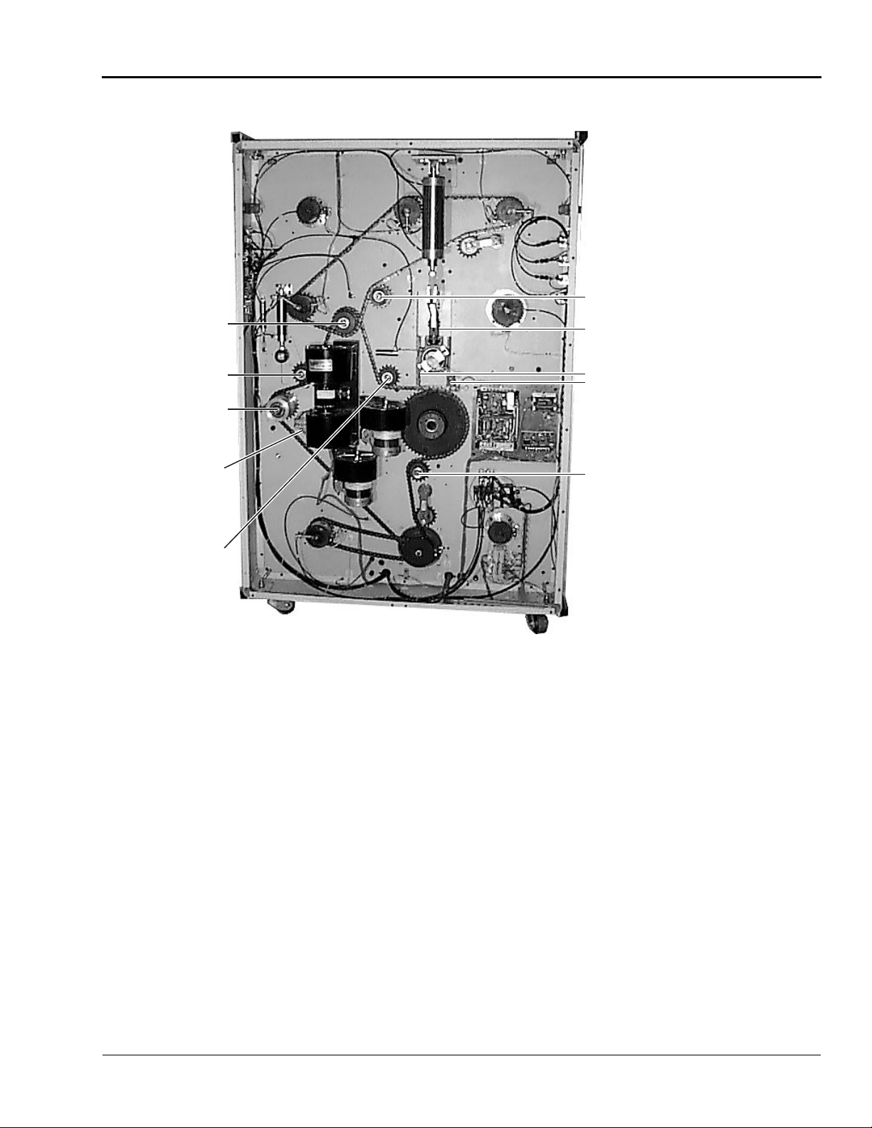
ORCA-IV Image Transfer Laminator Operation Manual
Maintenance and Troublesh ooting
© GBC Pro-Tech 1998 October
4-5
Grease Fitting
Grease Fitting
Grease Fitting
Pull Roll Grease Both
Sides, Bottom
Roll
Grease Main
Roll Bearings Both Sides,
Top and
Bottom Rolls
Grease Fitting
Keep Pins (3) Well Oiled (Monthly)
Disassemble and Grease (Yearly)
Lubricate Slides with
Grease
Grease Fitting
Figure 4-1: Grease Fittings
Page 44

Maintenance and Troubleshooting
ORCA-IV Image Transfer Laminator Operation Manual
4-6
© GBC Pro-Tech 1998 October
2XWSXW7URXEOHVKRRWLQJ*XLGH
Problem:
D waves in the image, not in the
laminate.
Hints:
• Check paper tension.
• Check relative moisture
content of the paper.
Problem:
Waves on only one side of the
output.
Hints:
• Check nip settings.
• Check for even paper tension.
• Check for proper alignment on
initial setup.
Problem:
D waves in the laminate.
Hints:
• Increase brake tension
on laminate.
• Check roll pressures.
• Check nip settings.
Feed
Direction
Problem:
Straight waves in the output.
Hints:
• Decrease clutch tension.
• Check operational settings for
materials being used.
Other Common Problems:
Problem:
Blistering in the image.
Hints:
• Increase speed or lower the operating
temperature.
Problem:
Coiling of encapsulated images.
Hints:
• Balance the upper and lower unwind brake
tension. Adjust cooling fans.
Problem:
Longitudinal waves or stuttering, jerking, or
excessive noise from the drive side of the
laminator.
Hints:
• Increase chain tension, decrease unwind
brake tension.
Page 45

ORCA-IV Image Transfer Laminator Operation Manual
Maintenance and Troublesh ooting
© GBC Pro-Tech 1998 October
4-7
Table 4-4: Machine Troubleshooting Guide
Problem
Number
Problem
Possible Cause
Corrective Action
1 No display.
2 Display reads 8888.
3 Display reads .0 and the
machine does not run.
4 Display missing the decimal
point (e.g. -reads 30 instead
of 3.0)
5 Display missing the decimal
point (e.g. -reads 30 instead
of 3.0) but the kick cables
and safety buttons have been
checked and the reset button
has been push ed.
6 Waiver on one side of paper/
vinyl.
a. Is there power to the unit? a. Check for power to the machine
(building circuit breaker is on,
main switch is on (|), and the
machine circuit breaker is on
(up)).
a. Is the machine reset? a. Make sure all safety buttons are
released (out). Be sure all kick
cables are reset and adjusted
properly. Press the machine reset
(above main switch). See
"Machine Reset Procedure" on
page 3-3.
a. Is the direction indicator (FWD/
REV) pressed?
b. Is the speed not turned up?
a. Is there a kick cable or safety but-
ton that has not been reset?
a. Press FWD or REV.
b. Turn up the speed control.
a. Make sure all safety buttons are
released (out). Be sure all kick
cables are reset and adjusted
properly. Press the machine reset
(above main switch).
See
"Machine Reset Procedure" on
page 3-3.
a. Is the kick cable stretched out of
adjustment?
a. Is the tension too low?
b. Does the roll lower unevenly?
c. Was there a misalignment on set
up?
d. Is there a bad roll of material?
e. Is the web loose only when first
starting or splicing?
f. Is there uneven nip pressure?
a. Verify that the kick cable is truly
resetting (listen, look). Adjust the
kick cable. See “Adjusting the
Kick Cable” on page 4-3.
a. Increase appropriate brake ten-
sion.
b. Adjust cylinder flow controls.
c. Measure from the side frame to
the edge of material in front and
back to verify that the material is
webbed through straight.
d. Try a different roll.
e. Raise and lower the roll (pop up
and down) to pull the initial loose
web straight and ti ght.
f. Call Technical Support to disas-
semble and lubricate the cylinder
lift linkage (qualified service
technician required).
Page 46

Maintenance and Troubleshooting
ORCA-IV Image Transfer Laminator Operation Manual
4-8
© GBC Pro-Tech 1998 October
7 Rewound material not even
Problem
Number
Problem
Possible Cause
Corrective Action
on edge.
8 Plastic slitter tube has devel-
oped a larger diameter where
the round knives cut causi ng
paper stress l i nes and paper
tearing at peal idler.
9 Rewind is not turning
10 Laminate paper rewind will
not turn and/or you cannot
set the pressure.
11 Roll is overheating.
a. Was the initial material webbing
straight?
b. Is the roll telescoped?
c. Is there excessive tension?
d. Is it a poor roll of film (soft end)?
a. Has th e slitter idler increased in
diameter at the point of contact
with the blades?
a. Is the rewind engaged in the
drive?
b. Is there air pressure?
a. Is the pull roll up? a. Lower the pull roll. The laminate
a. Is the IR sensor blocked?
b. Is the IR sensor misaligned?
c. Is there cool air blowing on the
roll?
d. Is there an electrical problem?
a. Measure carefully from sideframe
and straighten webbing.
b. Use end plates on all unwinds.
c. Lower the tension.
d. Try a new roll.
a. Sand and/or file down the higher
spots in the plastic tube.
b. Replace the slitter tube (note: use
as little pressure on the slitter as
possible to increase the life of the
slitter tube).
a. Line up the drive tang and side
shafts over to the drive side to
engage them.
b. Check for appropriate main air
supply or increase the air pressure
to the rewind.
paper rewind will not turn and the
pressure will not increase until
the pull roll is down.
b. Stop the motor to allow the web
force to be set.
a. Be sure nothing ever blocks the
path of the IR sensor.
b. Align the sensor.
c. Direct the cool air away from the
roll surface.
d. Call Technical Support.
Page 47

ORCA-IV Image Transfer Laminator Operation Manual
Maintenance and Troublesh ooting
© GBC Pro-Tech 1998 October
4-9
12 I pressed the motor forward
Problem
Number
Problem
Possible Cause
Corrective Action
button, but the rolls would
not turn!
13 I pressed the motor reverse
button, but the rolls would
not turn!
14 I pressed the main roll down
push button, but the roll did
not go down!
15 I pressed the main roll up
push button, but the rolls di d
not go up!
16 I pressed the pull roll down
push button, but the rolls di d
not go down!
a. Has a speed setting been set?
b. Are the doors closed and shafts
locked in?
c. Are the e-stop buttons pressed?
Are the kick cables reset?
d. Is there decimal on display?
e. Check motor fuses on the back of
machine.
a. see problem 12 a. See problem 12.
a. Is there air pressure to the
machine?
b. Is there at least 20 psi on the
gauge?
c. Are the e-stop push buttons
pressed and the kick cables reset?
d. Is the machine reset?
a. Is there air pressure to the
machine?
b. Is the machine reset?
a. Is there air pressure to the
machine?
b. Is there at least 20 psi on the
gauge?
c. Is the roll hook retracted?
d. Are the e-stop push buttons
pressed and the kick cables reset?
e. Is the machine reset?
a. Press the FWD or REV arrow and
turn the speed control up.
b. Close the doors and lock in the
unwind/rewind shafts.
c. Make sure all safety buttons are
released (out). Be sure all kick
cables are reset and adjusted
properly. Press the machine reset
(above main switch). See
"Machine Reset Procedure" on
page 3-3.
cable is truly resetting (listen,
look). Adjust the kick cable. See
“Adjusting the Kick Cable” on
page 3-3.
d. Press the machine reset (above
main switch). See "Machine
Reset Procedure" on page 3-3.
e. Remove fuses and replace, if nec-
essary. B e sure to replace with the
correct size fuses: two 6A fuses
for the motor and one 1A fuse for
the power supply.
a. Verify that the air supply is suffi-
cient (
b. Turn up regulator for main roll
pressure.
c. See problem 12.
d. See problem 12.
e. Reset the machine. See "Machine
Reset Procedure" on page 3-3.
a. Verify that the air supply is suffi-
cient (
b. Reset the machine. See "Machine
Reset Procedure" on page 3-3.
a. Verify that the air supply is suffi-
cient (
b. Increase the pull roll air pressure.
c. Dis connect and reconnect air
pressure to the machine and
observe pull roll locking mecha-
nism.
d. See problem 12.
e. Reset the machine. See "Machine
Reset Procedure" on page 3-3.
Verify that the kick
≤
100 psi).
≤
100 psi).
≤
100 psi).
Page 48

Maintenance and Troubleshooting
ORCA-IV Image Transfer Laminator Operation Manual
4-10
© GBC Pro-Tech 1998 October
17 I pressed the pull roll up
Problem
Number
Problem
Possible Cause
Corrective Action
push button, but the rolls di d
not go up!
18 I pressed the top roll temper-
ature control “ON” push button and nothing happens.
19 The display shows unusual
numbers or characters.
20 I press the preheater push
button and a “P” is displayed
on the control panel.
21 I pressed the cooling fan
push button and the fan did
not turn off.
22 I pressed the cooling fan
push button and the fan did
not turn ON.
23 I pushed the totalizer push
button, the display changed
to read 4 characters, but the
value does not increase.
24 I pressed the totalizer-reset
push button while in totalizer mode, and it did not
reset and other buttons on
the panel do not work either.
a. Is there air pressure to the
machine?
b. Is the machine reset?
a. Are the e-stop push buttons
pressed and the kick cables reset?
b. Is the machine reset?
c. Is there a decimal point in the dis-
play?
a. Is the machine reset? a. Reset the machine. See "Machine
a. This is normal. This shows that
you are in PREHEAT AUTO
mode.
a. Is the cooling fan toggle switch
set correctly?
a. Are the e-stop push buttons
pressed and the kick cables reset?
b. Is the machine reset?
a. Is the proximity switch that reads
the motor sensor teeth adjusted
properly?
b. Does the input light “X1” come
on when the proximity switch
comes on?
a. Is the machine reset? a. Reset the machine. See "Machine
a. Verify that the air supply is suffi-
≤
cient (
b. Reset the machine. See "Machine
Reset Procedure" on page 3-3.
a. See problem 12.
b. Reset the machine. See "Machine
Reset Procedure" on page 3-3.
c. Reset the machine. See "Machine
Reset Procedure" on page 3-3.
Reset Procedure" on page 3-3.
a. If you press the preheat button
again, it will go off.
a. The cooling fan push button is a
4-way toggle switch, keep pushing the button until the fan goes
off. From the off position, press
once to turn only the cooling idler
on, press twice to turn the cooling
tubes only on, press a third time
to turn on both the cooling id ler
and the cooling tubes, and press a
fourth time to turn the cooling
systems off.
a. See problem 12.
b. Reset the machine. See "Machine
Reset Procedure" on page 3-3.
a. Make adjustment and try again.
b. If the input light comes on, go to
problem 48.
Reset Procedure" on page 3-3.
100 psi).
Page 49

ORCA-IV Image Transfer Laminator Operation Manual
Maintenance and Troublesh ooting
© GBC Pro-Tech 1998 October
4-11
25 I pressed the totalizer-reset
Problem
Number
Problem
Possible Cause
Corrective Action
push button while in totalizer mode, and it did not
reset and other buttons on
the panel do not work either,
but the controls on the other
panel work.
26 My air supply is 100 psi, but
my control panel reads less
than 100 psi.
27 When I operate the machine
in reverse, an alarm goes off.
28 An alarm sounds rapidly
after a 10 second delay.
29 After 55 minutes of no activ-
ity, a 4 beep alarm sounds,
followed by a 30 se cond
delay
30 The alarm does not come on
for the conditions outlined
above.
31 When the rolls are stopped, I
pressed the switch to adjust
the pressure to the brakes or
clutches, and nothing happened.
32 When the rolls are moving, I
pressed the switches to
adjust the pressure to the
brakes and clutches, and
nothing happens.
33 I pressed the motor forward
push button and the arrow
light did not come on.
a. Is the machine reset?
b. Is there a problem with the key-
pad?
c. Is there a software problem?
a. Has the display panel been cali-
brated?
b. Is the pressure transducer faulty?
a. This is a normal safety function. a. No corrective action necessary.
a. Main rolls are down, and the rolls
are not turning.
a. The main roll is in the up position
and the temperature controller is
on.
a. Is there a technical problem with
the alarm?
a. Are the e-stop push buttons
pressed and the kick cables reset?
b. Is the machine reset?
a. This may be normal. When the
machine is running the computer
takes over the settings and adjusts
the pressure to the brakes and
clutches. The change that you
attempted to make may have been
too small to see on the gauge as a
percent allowable pressure for
that size roll.
a. Are the shafts locked in? a. Close the doors and lock in the
a. Reset the machine. See "Machine
Reset Procedure" on page 3-3.
b. Check/tighten the conn ector to
the keypad.
c. Call Technical Support.
a. Call Technical Support.
b. Call Technical Support.
a. Raise the rolls or run the machine
at a slow speed to increase the life
of the rolls.
a. If you’re not using the machine,
turn the temperature controller
off, or lower the roll and run the
machine at a slow speed. Failure
to do this will reduce the life of
your rolls and may cause permanent damage.
a. Contact Technical Support.
a. See problem 12.
b. Reset the machine. See "Machine
Reset Procedure" on page 3-3.
a. Push and release button (do not
hold). Try manual mode.
In automatic mode with the motor
off, set the web force. When it
starts to run, see calculated pressure sent to brake for that
required web force. Even though
you do not see a large increase in
the pressure on the display, feel
the web tension manually to see if
the brake tension has changed.
shafts, then try the motor.
Page 50

Maintenance and Troubleshooting
ORCA-IV Image Transfer Laminator Operation Manual
4-12
© GBC Pro-Tech 1998 October
34 I pressed the shaft engage
Problem
Number
Problem
Possible Cause
Corrective Action
push button and the shaft did
not engage.
35 The machine was running,
but stopped ab ruptly.
36 The machine was running,
but then the rolls went up
and the machine stopped
37 Nothing seems to work.
38 Slitter is not cutting.
39 Paper rips easily at the point
it is pulled off.
a. Are the guard doors closed?
b. Is the machine reset?
c. Are the e-stop buttons pressed
and the kick cables reset?
a. Has the machine blown a fuse?
b. Did you activate the kick cable?
a. Was the e-stop pressed?
b. Did you activate the kick cable?
a. Is the machine reset? a. Reset the machine. See "Machine
a. Is the blade adjusted properly?
b. Is the blade dull or damaged?
c. Is the bushing that mounts the
blade worn out?
a. Is the slitter tube enlarged? a. The plastic slitter tube can
a. Close the doors.
b. Reset the machine. See "Machine
Reset Procedure" on page 3-3.
c. See problem 12.
a. Check fuses on the back of the
machine.
b. Reset the kick cable.
a. Reset the e-stop and reset the
machine. See "Machine Reset
Procedure" on page 3-3.
b. Reset the kick cable and reset the
machine. See "Machine Reset
Procedure" on page 3-3.
Reset Procedure" on page 3-3.
a. Check blade adjustment. “Setting
the Slitter” on page 3-12
b. Replace blade.
c. Replace the bushing.
become enlarged from many cuts
in a close area. This causes the
edge of the paper to go around a
larger diameter at the slitter sta-
tion and causes small tears in the
paper’s edges which can lead to
the paper starting to tear all the
way across at the rear idler. The
solution is to sand/file down the
frequently used raised areas on
the slitter’s plastic tube.
Page 51

ORCA-IV Image Transfer Laminator Operation Manual
Warranty
© GBC Pro-Tech 1998 October
5-1
6HFWLRQ:DUUDQW\
IMPORTANT
/LPLWHG:DUUDQW\
GBC Pro-Tech Engineering Company, Inc. warrants
the equipment sold is free from defects in material and
workmanship for a period of one year from the date of
delivery to the customer for parts and ninety days (90)
from the date of d elivery to the c ustomer for l abor.
This warranty is the only warranty made by GBC ProTech and cannot be modified or amended.
([FOXVLRQV WR WKH :DUUDQW\
This warra nty specifically does not cover:
1. Damage to the laminating rolls caused by knives,
razor blades, other sharp objects, or failure caused
by adhesives.
2. Damage to th e machine caused by lifting, tilting,
and/or any attempt to position the machine other
than rolling on the installed casters on even surfaces.
GBC Pro-Tech’s sole and exclusive liability and the
customer’s sole and exclusive remedy under this
warranty shall be, at GBC Pro-Tech’s option, to
repair or replace any such defective part or product. These remedies are only available if GBC ProTech’s examination of the product di scl ose s t o GBC
Pro-Tech’s satisfaction that such defects actually
exist and were not caused by misuse, neglect,
attempt to repair, unauthorized alteration or modification, incorrect line voltage, contaminated air
supply, or by fire, accident, flood, or other hazard.
This warranty specifically does not cover damage to
the laminating rollers caused by knives, razor blades,
other sharp objects, failure caused by adhesives or
improper use of the machine. Warranty repair or
replacement does not extend the warranty beyond the
initial period from the date of delivery.
Unauthorized customer alterations will void this
warranty.
3. Improper use of the machine.
THE WARRANTY MADE HEREIN IS IN LIEU OF
ALL OTHER WARRANTIES, EXPRESS OR
IMPLIED, INCLUDING ANY WARRANTY OR
MERCHANTABILITY OR FITNESS FOR A PARTICULAR PURPOSE. GBC PRO-TECH WILL NOT
BE LIABLE FOR PROPERTY DAMAGE OR PERSONAL INJURY (UNLESS PRIMARILY CAUSED
BY ITS NEGLIGENCE), LOSS OF PROFIT OR
OTHER INCIDENTAL OR CONSEQUENTIAL
DAMAGES ARISING OUT OF THE USE OR
INABILITY TO USE THE EQUIPMENT.
Page 52

Warranty
ORCA-IV Image Transfer Laminator Operation Manual
5-2
© GBC Pro-Tech 1998 October
Blank page.
Page 53

ORCA-IV Image Transfer Laminator Operation Manual
Specifications
© GBC Pro-Tech 1998 October
6-1
6HFWLRQ6S HFLILFDWLRQV
Character istic
Specifications
Table 6-1: ORCA-IV Im age Transfer Laminator
Specifications
Dimensions
(L x D x H)
Weight Uncrated: 3060 lbs (1814 kg)
Main Rolls 62" (157 cm) roll face with high
Main Roll Opening
Material Uses transfer materials 0 - 54"
Speeds 0 to 10 fpm (0 to 3.1 mpm)for
Safety Features • All electrical and moving
86" x 48" x 73"
(2.2 x 1.2 x 1.7 m)
release silicon rubber coating for
54" wide materials
1.25" (3.2 cm) maximum opening
(0 - 137.2 cm) wide. Handles
materials on 3" (7.6 cm) ID cores
with material diameters up to 15"
(38.1 cm).
transfer process with variable
speed and 19 fpm (5.8 mpm) ,
reversible action, start and stop
controlled by the instrument
panel.
mechanical parts are located
in bolted cabinets
• Emergency stop buttons with
a reset button circuit
• Fully guarded with in terlocks
• Emergency stop kick cables
Options • Preheater module
Installation
Requirement
230VAC 50 or 60 Hz, three
phase, 45A per phase with preheater (35A per phase without
preheater) for 4 wire delta
hookup. 40A service without the
preheater and 50A service with
the preheater is required.
Filtered air at 1.5 cubic feet per
minute (cfm), 50 liters/minute at
a pressure of 100 pounds per
square inch (psi) (700 kPa)
Page 54

Specifications
ORCA-IV Image Transfer Laminator Operation Manual
6-2
© GBC Pro-Tech 1998 October
Blank page.
Page 55

ORCA-IV Image Transfer Laminator Operation Manual
© GBC Pro-Tech 1998 October
7-1
,QGH[
,
1XPHULFV
3M
3-12
$
Accessory pack
Air supply
Audible signals
2-4
2-2
3-3
&
Centering the web
Chain
Lubrication
Changing film and paper
Cleaning
Controls
4-1
Cabinet and covers
Doors
4-2
Rolls
4-1
Front brake panel
Front control panel
Rear brake panel
Rear control panel
3-13
4-3
3-6
3-10
3-8
3-14
4-2
3-4
Installation requirements
International shipments
Isopropyl alcohol
4-1
-
Jumper configurations
2-1
.
Kick cable
1-2, 2-6
Adjusting
4-3
/
Laminate adhesives
Leveling
Lubrication
2-5
4-3
3-12
0
Main roll opening
Main rolls
Maintenance schedule
Material
Motor
6-1
6-1
2-7
6-1
4-1
2-1, 6-1
2-5
(
Emergency stop buttons
Environment
2-1
)
Film
3-12
Loading
Film spacing
Front clutch/brake panel
Front control panel
FWD/REV switch
3-11
3-14
3-4
4-2
*
Grease fittings
4-3
+
Heater
2-7
Controller
Heating
2-7
3-11
1-2, 2-6, 3-2
3-6
1
Nip
1-1, 1-3, 3-1
2
Options
6-1
3
Paper
3-12
Positioni ng the film
Preinstallation checklist
Process control charts
3-13
2-1
3-15
5
Rear clutch/brake panel
Rear control panel
Recommended materials
Reset button
Reset procedure, machine
Reset, machine
Rexam
Riggers
Roll to roll transfer
Rubber cement eraser
1-3
3-3
3-12
1-5, 2-4
3-10
3-8
3-15
4-1
3-12
1-3
Page 56

ORCA-IV Image Transfer Laminator Operation Manual
7-2
© GBC Pro-Tech 1998 October
6
Safety
1-1
Safety features
Safety hazard decals
Safety information
Safety labels
Setup
3-11
Setup procedure
Shutdown
Shutdown, machine
Slitter
3-12
Specifications
Dimensions
Installation requirements
Main roll opening
Main rolls
Material
Options
Speeds
Weight
Speeds
Splicing
6-1
Paper
Vinyl
6-1
1-1, 3-1
1-5
2-5
3-16
6-1
6-1
6-1
6-1
6-1
6-1
3-14
3-14
1-7
3-16
6-1
6-1
7
Technical support
Call 1-608-246-8844 or fax 1-608-246-8645
8
Unpacking
Crate
Upper main roll
2-4
2-4
1-4
9
Vinyl tran sfer
Vinyl transfer and overlamination materials
3-15
:
Warnings and cautions
Warranty
5-1
Exclusions
5-1
1-1
4-4
3-12
 Loading...