

Page 1
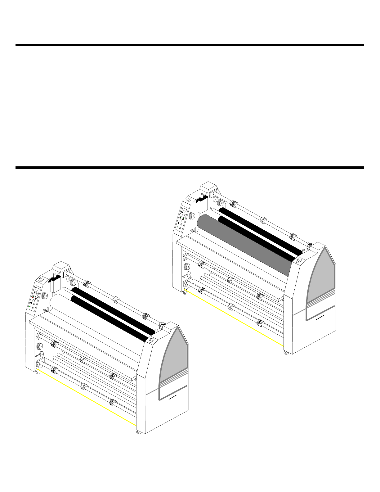
ORCA III/ ORCA III T
OPERATION & MAINTENANCE
MANUAL
© February 2001 GBC Films Group
Do not duplicate without written permission.
III T
A
C
R
O
III
A
C
R
O
Pro - Tech
GBC
Pro - Tech
GBC
GBC Pro - T ech
4151 Anderson Road
DeForest, WI 53532
Revision : Ph: ( 608 ) 246 - 8844
Part number : 930 - 062
Fx: ( 608 ) 246 - 8645
Page 2

Read me fileOrca III/ Orca III T Operation and Maintenance Manual
Read Me File . . . . . . . . .
The information in this publication is provided for reference and is believed to be accurate and complete. GBC Films Group is not liable for errors in this publication or for incidental
or consequential damage in connection with the furnishing or use of the information in this
publication, including, but not limited to, any implied warranty of fitness or merchantability for
any particular use.
GBC Films Group reserves the right to make changes to this publication and to the
products described in it without notice. All specifications and information concerning products
are subject to change without notice.
Reference in this publication to information or products protected by copyright or patent
does not convey any license under the rights of GBC Films Group or others. GBC Films
Group assumes no liability arising from infringements of patents or any other rights of third
parties.
This publication is copyrighted © 2000 by GBC Films Group. All rights reserved. The
information contained in this publication is proprietary and may not be reproduced, stored,
transmitted, or transferred, in whole or in part, in any form without the prior and express written
permission of GBC Films Group.
The following information will explain how to move around within the electronic version
of this publication. The hand will change to a pointer finger identifying hyperlinked areas. When
moving from page to page, use
PAGE, use
from view to view, use
VIEW.
Should you find an error within this publication or would like to make a suggestion,
please utilize the fax correspondence sheet following this read me file and fax it to the number
provided. Your comments and help will ensure up to date information. Thank you.
to go back one PAGE and use to advance one PAGE. When moving
to return to a previous VIEW and use to advance to the next
to return to the first PAGE, use to advance to the last
© GBC Films Group February 2001
Page 3

Read me file Orca III/ Orca III T Operation and Maintenance Manual
This page intentionally left blank.
© GBC Films Group February 2001
Page 4

Fax Correspondence
Fax number : ( 608 ) 246 - 8645 Date :
To : Technical Coordinator at GBC Pro-Tech
4151 Anderson Road
DeForest, WI 53532
From :
Company :
Address :
Phone number : ( ) Fax number : ( )
Read me fileOrca III/ Orca III T Operation and Maintenance Manual
Re : Orca III/ Orca III T Operations and Maintenance Manual ( 930062 )
Section #: Page #:
Correction (s):
Additional comments:
© GBC Films Group February 2001
Page 5

Read me file Orca III/ Orca III T Operation and Maintenance Manual
This page intentionally left blank.
© GBC Films Group February 2001
Page 6

Section 1.0 Safety
1.1 Symbols ......................................................................................................1 - 1
1.2 Pneumatic safety ........................................................................................1 - 2
1.3 Safety features ............................................................................................1 - 2
1.4 Mechanical safety ......................................................................................1 - 4
1.5 Heating safety .............................................................................................1 - 4
T able of ContentsOrca III/ Orca III T Operation and Maintenance Manual
Table of Contents
1.6 Maintenance safety ....................................................................................1 - 5
1.7 Installation ..................................................................................................1 - 5
1.8 Operation ...................................................................................................1 - 8
1.9 Applications ...............................................................................................1 - 10
1.10 Troubleshooting .......................................................................................1 - 12
1.11 Maintenance ............................................................................................1 - 12
1.12 Label Explanation ....................................................................................1 - 14
Figure 1.12.1 Label Location ....................................................1 - 16
Section 2.0 Warranty
2.1 Limited warranty information ....................................................................2 - 1
2.2 Exclusions to the warranty ........................................................................2 - 1
© GBC Films Group February 2001
Page I
Page 7

T able of Contents Orca III/ Orca III T Operation and Maintenance Manual
Section 3.0 Specifications
3.1 General .......................................................................................................3 -1
3.2 Consumables................................................................................................3 - 2
3.3 Function ......................................................................................................3 - 3
3.4 Electrical ....................................................................................................3 - 4
3.5 Dimensions .................................................................................................3 - 5
Section 4.0 Installation
4.1 Pre-installation check list ..........................................................................4 - 1
Figure 4.1.1 Suggested floor layout ..............................................4 - 3
4.2 Know your machine ...................................................................................4 - 4
4.3 Unpacking ..................................................................................................4 - 5
4.4 Shrink wrapped .........................................................................................4 - 5
4.5 Crated .........................................................................................................4 - 6
4.6 Accessory pack ..........................................................................................4 - 9
4.7 Electrical connection ..................................................................................4 - 9
4.8 Air connection ............................................................................................4 - 11
4.9 Installing levelers .......................................................................................4 - 12
4.10 Leveling ...................................................................................................4 - 13
Page II
© GBC Films Group February 2001
Page 8

4.11 Unwind/ rewind brake .............................................................................4 - 14
4.12 Slitter assemblies .....................................................................................4 - 15
4.13 Calibrations .............................................................................................4 - 16
Section 5.0 Operations
5.1 Power ON/ OFF .........................................................................................5 - 1
5.2 Front control panel ....................................................................................5 - 2
T able of ContentsOrca III/ Orca III T Operation and Maintenance Manual
Figure 5.2.1 Front control panel ............................................................5 - 5
5.3 Rear control panel ......................................................................................5 - 6
Figure 5.3.1 Rear control panel ............................................................5 - 9
5.4 Setting temperature ...................................................................................5 - 10
5.5 In case of an emergency ...........................................................................5 - 11
5.6 Film loading/ unloading ...........................................................................5 - 12
5.7 Main roller nip ..........................................................................................5 - 14
5.8 Pull roller nip ............................................................................................5 - 14
5.9 Unwind brake tension ...............................................................................5 - 15
5.10 Rewind brake tension .............................................................................5 - 15
5.11 Shutdown procedure ................................................................................5 - 16
© GBC Films Group February 2001
Page III
Page 9

T able of Contents Orca III/ Orca III T Operation and Maintenance Manual
Section 6.0 Applications
6.1 Temperature chart .....................................................................................6 - 1
6.2 Helpful hints ...............................................................................................6 - 2
6.3 Temp conversion chart ...............................................................................6 - 3
Figure 6.3.1 Temperature conversion chart .................................6 - 4
6.4 Charts and diagrams .................................................................................6 - 5
Figure 6.4.1 Poly in/ Poly out diagrams ........................................6 - 5
Chart - 0 ( blank chart ) ..........................................................................6 - 6
Diagram - 0 .............................................................................................6 - 7
Chart - 1 ( 1 pass mounting ) ...................................................................6 - 8
Diagram - 1 .............................................................................................6 - 9
Chart - 2 ( PSA decaling ) .....................................................................6 - 10
Diagram - 2 ............................................................................................6 - 11
Chart - 3 ( Roll to roll psa decaling ) .....................................................6 - 12
Diagram - 3 ............................................................................................6 - 13
Chart - 4 ( Mounting a PSA decal - Main rollers ) ................................6 - 14
Diagram - 4 ............................................................................................6 - 15
Chart - 5 ( Mounting a PSA decal - Pull rollers ) ..................................6 - 16
Diagram - 5 ............................................................................................6 - 17
Chart - 6 ( Thermal decaling ) ..............................................................6 - 18
Page IV
© GBC Films Group February 2001
Page 10

T able of ContentsOrca III/ Orca III T Operation and Maintenance Manual
Diagram - 6 ............................................................................................6 - 19
Chart - 7 ( Thermal encapsulation ) ......................................................6 - 20
Diagram - 7 ............................................................................................6 - 21
Chart - 8 ( Roll to roll thermal encapsulation ) .....................................6 - 22
Diagram - 8 ............................................................................................6 - 23
Chart - 9 ( PSA encapsulation - Main rollers ) ......................................6 - 24
Diagram - 9 ............................................................................................6 - 25
Chart - 10 ( Roll to roll PSA encapsulation ) ........................................6 - 26
Diagram - 10 ..........................................................................................6 - 27
Chart - 11 ( PSA encapsulation - Pull rollers ) ......................................6 - 28
Diagram - 11 ..........................................................................................6 - 29
Chart - 12 ( Vinyl transfer with trimming ) ...........................................6 - 30
Diagram - 12 ..........................................................................................6 - 31
Chart - 13 ( Vinyl transfer no trimming ) ..............................................6 - 32
Diagram - 13 ..........................................................................................6 - 33
Chart - 14 ( Over-lamination of transferred vinyl images ) ..................6 - 34
Diagram - 14 ..........................................................................................6 - 35
Chart - 15 ( Roll to roll vinyl transfer ) .................................................6 - 36
Diagram - 15 ..........................................................................................6 - 37
© GBC Films Group February 2001
Page V
Page 11

Table of Contents Orca III/ Orca III T Operation and Maintenance Manual
Section 7.0 Troubleshooting
7.1 Wave problems ..........................................................................................7 - 1
7.2 Film problems .............................................................................................7 - 3
7.2.1 Thermal laminates ........................................................................7 - 3
7.2.2 Pressure sensitive .........................................................................7 - 3
7.3 Machine problems .....................................................................................7 - 4
7.4 Glossary ......................................................................................................7 - 5
Section 8.0 Maintenance
8.1 Maintenance schedule ...............................................................................8 - 1
8.2 Cleaning the rollers ..................................................................................8 - 2
8.3 Dust - Pre-coated boards ............................................................................8 - 3
8.4 Dirt and PSA adhesive - Alcohol and cloth ...............................................8 - 3
8.5 Thermal adhesive .......................................................................................8 - 4
8.6 Clean the laminator ....................................................................................8 - 5
8.7 Clean the control panels .............................................................................8 - 6
8.8 Chain tensioning .........................................................................................8 - 6
8.9 Lubrication .................................................................................................8 - 7
Figure 8.9.1 Grease fitting points ...........................................................8 - 9
Page VI
© GBC Films Group February 2001
Page 12
1.0 Safety
CAUTIO N
Do n o t attempt to o p era te y ou r O r ca III/
Orca III T laminator until you have read
this s ec tio n c a re fully!
SafetyOrca III/ Orca III T Operation and Maintenance Manual
CAUTION
Indicates a potentially hazardous situation
which, if not avoided, could result in minor
or moderate injury, or alerts against unsafe
practices or alerts against actions which
could damage the product.
Your safety, as well as the safety of others, is
important to GBC Films Group. This section contains
important safety information.
The following symbols are used throughout
this manual to indicate Information, Caution,
Warning, Danger and Electrical Shock conditions.
1.1 Symbols
WARNING
Indicates a po tentially hazardou s situation
which, if not avoided, could result
in se rio u s in ju ry .
DANGER
Indicates an imminently hazardous situation
which, if not avoided, could result in death
or serious injury.
INFORMATION
Indicates helpful information that should be
considered before, during, or after an
action, step or procedure is given.
© GBC Films Group February 2001
ELECTRICAL
SHOCK
Indicates an electrical shock situation which,
if not avoided, could result in serious
paralyzation of the body or death.
Page 1 - 1
Page 13
Safety Orca III/ Orca III T Operation and Maintenance Manual
1.2 Pneumatic safety
The Orca III/ Orca III T laminator has been
designed with safety as a primary consideration;
however, you must become thoroughly familiar with
the controls, proper operation, proper service
procedures and safety features of the laminator before
using or servicing the unit.
The pneumatic system used to provide downward pressure on the top main roller and the top pull
roller is capable of producing great amount of forces.
This force is applied to any object presented in the
opening (called the nip) between the two rollers.
CAUTION
1.3 Safety features
Important safety features of the Orca III/ Orca
III T laminator are the emergency stop push buttons
(E-STOP), the emergency stop cables (E-CABLE)
and the photo electric sensors (PHOTO-EYE). It is
recommended that you become thoroughly familiar
with each of these safety features purpose and how to
use them in the event of an emergency.
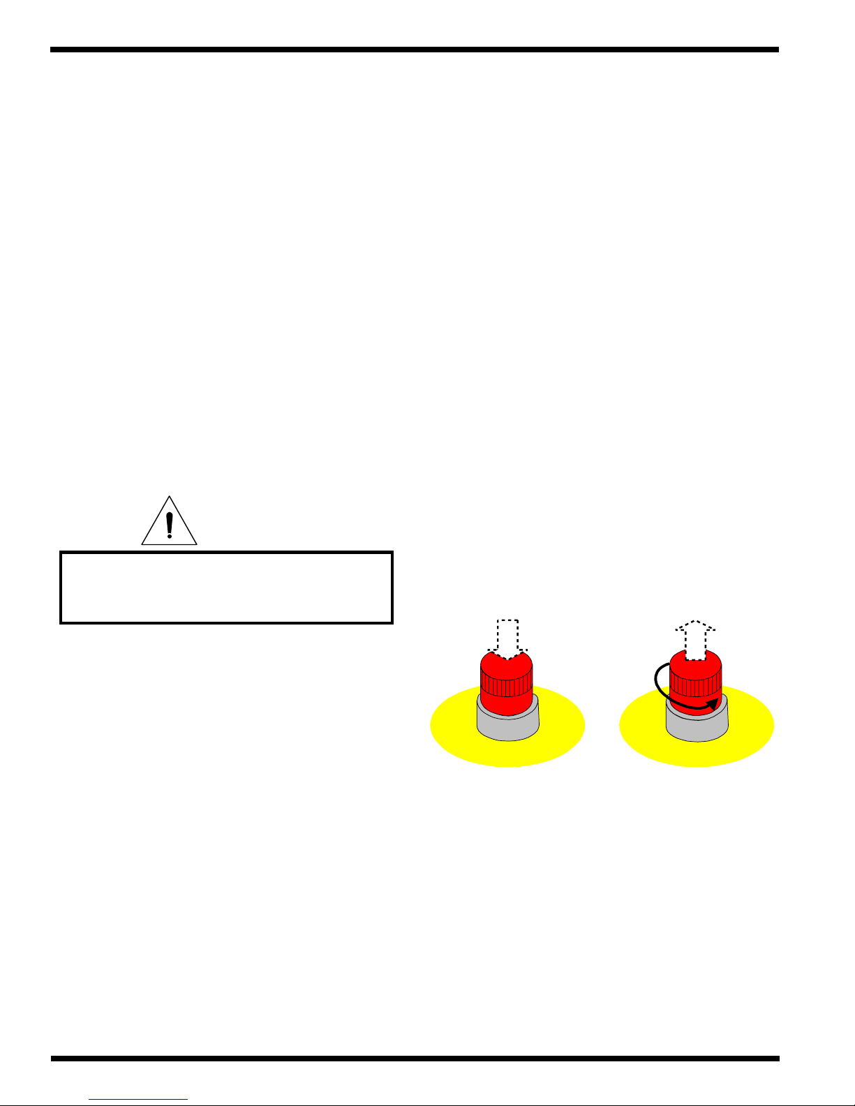
E- STOP
T o engage any one of the four E-STOPs, press
the push button down. Any one of these, when
engaged, removes power to the motor and opens the
main roller and pull roller nips.
Objects other than m edia, film or app roved
substrates, will cause irreparable damage
to the rollers if caugh t in the n ip.
Use care in lowering the top main and/ or pull
rollers. Know how to react quickly in an emergency.
The top main laminator roller UP-DOWN switch is
located on the front control panel. The top pull roller
UP-DOWN switch is located on the rear control panel.
This switch controls the up and down motion of the
top pull roller .
Before pressing either of these switches to the
DOWN position, ensure that nothing is in the nip areas. If any problem or danger should occur, depressing any of the emergency stop push buttons or engaging the emergency cables, described in Section 1.3,
stops the rollers from closing and raises them completely.
E
M
E
R
G
Engaged
Push
E
N
P
O
T
S
Y
C
E
Turn
E
M
R
G
E
C
N
Disengaged
P
O
T
S
Y
To continue operation, all E-STOPS must be
in the up position. To reset the E-STOP, twist the
button 1/4 turn counter clockwise and reset the main
roller UP-DOWN switch to UP.
Page 1 - 2
© GBC Films Group February 2001
Page 14

SafetyOrca III/ Orca III T Operation and Maintenance Manual
E- CABLE
To engage the front or rear E-CABLE, push
in on the cable using your foot. Either cable, when
engaged, removes power to the motor and opens the
main roller and pull roller nips. The E-CABLE are
provided in the event you are unable to reach one of
the four E-STOPs.
PHOTO-EYE
The Orca III/ Orca III T is equipped with three
sets of PHOTO-EYEs, one at the main roller nip,
one behind the pull roller nip and one in front of the
pull roller nip. The PHOTO-EYEs, when blocked by
an object, stop the rollers from turning and will resume
turning when the sensor is no longer blocked.
This safety feature not only protects the
operator but also protects objects from entering the
rollers nip causing damage. The PHOTO-EYEs are
calibrated at time of installation.
With the FWD/ REV switch in the FWD
position, the PHOTO-EYE at the front of the main
roller nip (1) and the rear of the pull roller nip (3) are
engaged.
Press in or down
O
GBC
h
c
e
T
-
o
r
P
III
A
C
R
To continue operation, reset the main roller
UP-DOWN switch to UP and continue on with
operation. The E-CABLE automatically resets itself
when the cable springs back to it’s original position.
All E-STOPs must be in the unlatched position as
well.
The E-CABLE may be adjusted if you feel
the cable is too sensitive or too loose. Contact your
local service representative for this adjustment.
( 2 )
Front pull roller
photo-eye
( 3 )
Rear pull roller photo-eye
( 1 )
Main roller
photo-eye
With the FWD/ REV switch in the REV
position, the PHOTO-EYE at the front of the pull
roller nip (2) is engaged only.
© GBC Films Group February 2001
Page 1 - 3
Page 15
Safety Orca III/ Orca III T Operation and Maintenance Manual
1.4 Mechanical safety
WARNING
Never remove or open any guarding or
covers from th e m a chin e. Th ese a re
placed for you protection as well as
the protection o f the m a ch ine.
WARNING
Never place hands, fingers or objects
through any opening of the side fram e. Your
hand or fingers may be pinched or crushed
or you m ay cau se d am g e to the machine.
1.5 Heating safety
The heating components of the Orca III/ Orca
III T can reach temperatures of over 200 oF ( 100 oC ).
DANGER
At these temperatures there is a danger of
severe burn if the rolls are touched during
setup, operation or servicing.
In the event of a run away heat failure, the
machine is equipped with a thermal cut off switch.
This switch will remove power to the heating system
before any damage can be caused by the run away
heat failure.
WARNING
W hen sw inging out or in an unw ind,
keep hands and fingers away from
the pivot end. Your hand or
fingers may be pinched.
WARNING
Keep hands and fingers away from the
ends of the removable idlers when
rem oving o r installin g th em at
various loca tions on th e m ach ine.
IN FORMATION
If run aw a y h ea t failure occu rs, call
your loca l service represen tative
before using the m achine again.
CAUTION
Neve r leave th e roller in the do w n p osition
w ith o u t r ollin g wh e n th e ro ller s a r e h e a ted .
This w ill ca u s e d a mage to th e r o ller s.
Page 1 - 4
© GBC Films Group February 2001
Page 16
SafetyOrca III/ Orca III T Operation and Maintenance Manual
1.6 Maintenance safety
Any maintenance requiring the cabinets to be
opened with electrical power connected should be only
performed by a qualified service technician.
INFORMATION
Only a qualified service technician should
perform any procedure requiring the
cabinet doors to be opened.
1.7 Installation
The following symbols are positioned at
various points in Section 4 Installation.
CAUTION
Failure to follow the pre-installation check
list can result in damage to the laminator.
The word qualified is defined as;
Qualified ;
• Any engineer that has experience with
electrical and mechanical design of lamination
equipment. The engineers should be fully aware of
all aspects of safety with regards to lamination
equipment.
• Any commissioning or service engineer must
be of competent nature, trained and qualified to GBC
Films Group standards to fulfill that job. This person
will have completed and passed the full service
training course from GBC Films Group.
WARNING
The operating environment must be free of
dust, flammable liquids and vapors. You can
be injured by inhaling chemical vapors.
WARNING
Vapor build up or stored flammable liquids
can cause a fire. Excessive dust can damage
the laminator.
CAUTION
• Any GBC T echnician, GBC Specialist, and /
or GBC Films Group T echnician that has been through
the GBC Pro-Tech service training course.
© GBC Films Group February 2001
Do not locate the laminator where air is
blowing directly on the machine. The air
flow can cool the rolls unevenly and result
in poor output quality.
Page 1 - 5
Page 17
Safety Orca III/ Orca III T Operation and Maintenance Manual
WARNING
Th e Orca III/ Orca III T Lam in ator is a
large and h eav y p iece of eq u ipm en t. It is
necessary to employ L IC E N S E D RIGG E R S
O N LY to move th e la mina tor . It is n ot
designed to be tipped up or sideways in any
way. Such action disturbs the exact
alignme n t o f th e ro llin g p a r ts o f the m ac h in e
and requires extensive re-alignment. You
can b e cru shed o r seriou sly injured .
INFORMATION
ALL SHIPMENTS ARE EX-WORKS.
At our
dock, title passes to the buyer. Please review
your insurance coverage prior to shipment,
as you are responsible for all subsequent
freight charges and risks.
INFORMATION
Depending on the destination and customer
preference, your machine may be shipped in
various ways. The laminator may arrive
shrink wrapped or in a plywood crate on a
skid. Please follow the unpacking procedure
that pertains to your method of shipment.
CAUTION
Do not use a knife or other sharp object to
remove the shrink wrap from around the
laminator. You can cause irreparable
damage to the rollers.
INFORMATION
Do not attempt to move the laminator across
without trained and qualified riggers. You
Before signing the Bill of Lading, you
should be sure to inspect the crate
and / or pallet for signs of damage or
missing items; if applicable, make
note of this on the Bill of Lading.
WARNING
The unpacking process requires at least two
people. You can be severely injured, crushed
or cause damage to the laminator.
WARNING
anything other than a flat level surface
can be crushed or seriously injured.
IN F O RM A T ION
GBC Film Group's warranty does not
cover malfun ction of the equipm ent du e to
mishandling and / or tipping. GBC Films
Gr o u p b ea rs n o re sp o n sib ility fo r p ers on a l
injury or damage due to moving the
lam in a to r im p r op e rly .
Page 1 - 6
© GBC Films Group February 2001
Page 18
SafetyOrca III/ Orca III T Operation and Maintenance Manual
CAUTION
Do not allow the top to fall into the crate. It
can damage the laminator.
INFORMATION
Do not put packing screws on the floor.
They can cause problems when trying to roll
the laminator into position or you can
become injured if stepped on.
INFORMATION
About recycling: The crate components can
be reused for shipping the laminator again
or can be disassembled and the wood and
screws recycled. The shrink wrap is not
recyclable, so it must be discarded.
INFORMATION
En su re sufficien t space f or op en ing of the
cabinets for maintenance and servicing.
CAUTION
A second person must support the side
labeled 5 in Figure 4.5.1 It can fall and
damage the laminator or cause harm to you
and others.
WARNING
Do not attempt to use the ramps if they are
not secured to the pallet. Ensure the pallet is
on a flat even surface before attempting to
roll the machine off.
ELECTRICAL
SHOCK
Only a qualified electrician should connect
power to the laminator. You can be severely
shocked, electrocuted or cause a fire if
power is improperly applied.
ELECTRICAL
SHOCK
On ly a qu alified electrician sho u ld verify
the voltage. Yo u can b e severely sh ock ed ,
electrocuted or ca use a f ire.
© GBC Films Group February 2001
Page 1 - 7
Page 19
Safety Orca III/ Orca III T Operation and Maintenance Manual
1.8 Operation
WARNING
Do n o t opera te the m a ch ine w ith th e
control side or drive side cabinet
in th e o p en p o s itio n .
various points in Section 5 Operation.
The following symbols are positioned at
WARNING
ELECTRICAL
SHOCK
Do not op er a te th e la m inator if th e p ower
cord is damaged or frayed. You can be
severely shock ed , electrocuted o r cau se a
fire. Contact a qu alified electrician to
replace the cor d.
IN F OR MATIO N
Th e u pp er m a in roller an d the u p per p u ll
rolle r s h o u ld b e in th e ra is ed p o s itio n .
Do not wear ties, loose fit clothing or
dangling jewelry while operating or
servicing the laminator. These items can get
caught in the nip and choke you or you can
be crushed or burned.
WARNING
W h en the lam in ator rollers are in
motion, keep hands and fingers
away from the nip of the rollers.
You may be CRUSHED or BURNED!
ELECTRICAL
SHOCK
Th ese calibration s req uire th e lam ina tor
to be po w ered u p w h ile the cabin ets
are open ed .
Page 1 - 8
IN FO RMAT ION
Th e la minato r will only turn o n if
all E-ST OPs are un latched .
IN FO RMAT ION
Th e cen ter pos ition is to preven t jam ming
of the m otor when ch an gin g d irections
© GBC Films Group February 2001
Page 20

SafetyOrca III/ Orca III T Operation and Maintenance Manual
IN FO RMAT ION
Top tem p eratu re con trol un it on/ o ff
switch must b e o n to t u r n t h e lo wer
temp erature co n trol unit to on .
IN FO RMAT ION
W h en d ecreasin g p ressu re, allow the
pressure g au ge to dro p b elow the desired
value, then in crease p ressu re to th e set
pressure d esired . Th is allow s fo r a more
accura te pressu re read ing .
IN FORMATION
When requiring top and bottom heat, it is
recom m en d ed to set both tem p eratu res to
the s a me set point.
INFORMATION
Th e m a xim u m set p oint tem p eratu re
is 290
o
F ( 143 oC ).
IN FO RMAT ION
W hen an emergency stop feature is activated
an d th e main r o ll is in the up p o si tio n , th e
pu ll r o ll will on ly s ta y in the u p positio n
until the em ergen cy stop fea ture is
deactivated.
IN FORMATION
INFORMATION
Th e minim u m set p o in t te m p e ra tu r e
o
is 32
F ( 0 oC ).
IN FO RMAT ION
W hen a safety feature is engaged, the
upper rollers raise and power to
the drive m o tor is rem ov ed.
Th e m o tor m u st be en ga ged fo r the co oling
fans to t u r n o n. If th e fa n sw it ch is in th e
"o n " p o s ition, the fa n s will au to matica lly
turn on wh en the motor is engaged.
© GBC Films Group February 2001
IN FO RMAT ION
Th e u pp er m a in ro ller UP / DOW N switch
resets the ma in ro ller to the correct po sition.
Page 1 - 9
Page 21
Safety Orca III/ Orca III T Operation and Maintenance Manual
1.9 Applications
CAUTION
Do n o t use an o pen b lade to cu t
the w eb nea r th e rollers.
You ca n p u t cuts into th e rollers!
INFORMATION
The nip can only be changed with the
upper roller in the up position.
IN FO RMAT ION
This w ill p re v ent the p u ll r o llers f ro m
contacting if the a ir shou ld be removed.
The following symbols are positioned at
various points in Section 6 Applications.
IN FORMATION
Beca use th e O rca III T h as a n u p p er
Teflon coa ted ro ller, your resu lts m ay
vary when d oing an encapsulation process.
TM
WARNING
Do not wear ties, loose fit clothing or
dangling jewelry while operating or
servicing the laminator. These items can get
caught in the nip and choke you or you can
be crushed or burned.
Page 1 - 10
IN FO RMAT ION
For o p timal tempera tu r e s ettin g s o f
various laminates, contact your
supp lier or sales rep resen tative.
IN FO RMAT ION
Gen eral ru le: Sm aller prin ts requ ire m ore
speed or less tem pera ture. L arg er p rints
require less sp eed o r m o re tem per ature.
© GBC Films Group February 2001
Page 22
SafetyOrca III/ Orca III T Operation and Maintenance Manual
IN FO RMAT ION
Use film brake tension to control the
separa tion po int of the r elease liner.
INFORMATION
Sp e ed s a n d temper a tu re s will affe c t th e
bond strength of thermal adhesives.
IN F OR MA T ION
IN FORMATION
Excessive brake tension may cause the
imag e to curl. A lw ays u se the minimum
amoun t of brake for the job.
CAUTION
Excess pressure can damage the laminating
rollers. Alway s u se the m in imu m roll
pressure n ecessa ry to co m p lete the task.
Not all papers and inks are compatible with
ther mal film s . T e st th e co mbin a tio n s f irst.
IN F OR MATIO N
Th e m o un t ad h esive m u st no t exceed 1 in.
the w idth of the substrate. If it does, you
w ill e xp e rie n ce c omplications with th is
application.
IN FO RMAT ION
Never stop the lam inator when an image is
within the n ip of either set of ro llers.
IN FO RMAT ION
Lam inates and papers should always be
stored in a co n trolled env ironment.
INFORMATION
Ex c es siv e pressu r e will cause the
substrate to bow or flatten.
© GBC Films Group February 2001
Page 1 - 11
Page 23
Safety Orca III/ Orca III T Operation and Maintenance Manual
1.10 Troubleshooting
The following symbols are positioned at
various points in Section 7 Troubleshooting.
WARNING
Do not wear ties, loose fitting clothing or
dangling jewelry while operating or
servicing the laminator. These items can get
caught in the nip and choke you or you can
be crushed or burned.
1.11 Maintenance
The following symbols are positioned at
various points in Section 8 Maintenance.
WARNING
Do not wear ties, loose fit clothing or
dangling jewelry while operating or
servicing the laminator. These items can get
caught in the nip and choke you or you can
be crushed or burned.
INFORMATION
For optimal temperature settings of
various laminates, contact your
supplier or sales representative.
WARNING
Do not wear ties, loose fitting clothing or
dangling jewelry while operating or
servicing the laminator. These items can get
caught in the nip and choke you or you can
be crushed or burned.
INFORMATION
Improper maintenance, can
result in poor output quality.
ELECTRICAL
SHOCK
Remove power from the laminator before
servicing. You can be severely shocked,
electrocuted or cause a fire.
INFORMATION
Below is a recommended maintenance
schedule. Before performing any of the steps
listed, read through the procedures first.
Please follow the instructions pertaining to
the step you are performing.
Page 1 - 12
© GBC Films Group February 2001
Page 24
SafetyOrca III/ Orca III T Operation and Maintenance Manual
CAUTION
Use o nly isop rop yl alcoh ol or ru b b er cem en t
eraser to clean th e rollers. Ha rsh chemicals
like toluene, aceton e, or MEK can d estroy
the silicone covering of th e rolls.
CAUTION
Exer cise care w h en cleanin g the la m inating
rolle rs with 80 % is op r o p y l a lco h o l:
Us e o nly in a well ve n tila ted area
W ear rubber gloves
Use o nly on co ol rolls
CAUTION
CLEANING HEATED ROLLERS CAN
IGNITE THE FUMES!
CAUTION
Do NO T pick or pull heat activated adhesive
off the rolls w h en th ey a re cold. Y o u ca n
cause irrepa rab le da m ag e to the
lam inating r ol ls.
CAUTION
Ex c es siv e pressu r e c an des tro y th e silico n e
layer by pressing to hard or scrubbing
too long in one spot.
IN FO RMAT ION
Keep the terry cloth tow el k ind of d am p to
mak e th e rub b ing of the roller sm ooth .
ELECTRICAL
SHOCK
Do not use liquid or aerosol cleaners on the
laminator. Do not spill liquid of any kind on
the laminator. You can be severely shocked,
electrocuted or cause a fire. Use only a damp
cloth for cleaning unless other wise
specified.
© GBC Films Group February 2001
Page 1 - 13
Page 25
Safety Orca III/ Orca III T Operation and Maintenance Manual
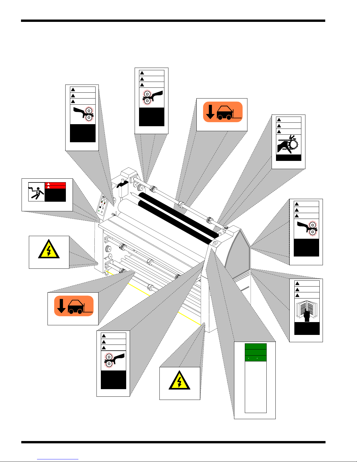
1.12 Label locations
WARNING
!
ACHTUNG
Posted at various locations on the Orca III/
Orca III T Laminator are important safety labels. Pay
careful attention to these labels at all times! Figure
1.12.1 illustrates the location of each of these labels.
!
DANGER
!
GEFAHR
HAZARDOUS
VOLTAGE
To be serviced only
by trained and
authorized personnel.
Lockout power b efore
servicing
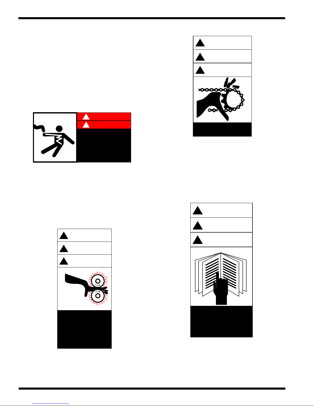
Moving Parts: Keep hands and fingers away . You
may be crushed and/ or cut.
!
M ISE EN GARDE
!
Moving parts can
crush and cut.
Hazardous Voltage: Do not open these cabinets.
This machine is to be serviced only by trained and
authorized personnel.
WARNING
!
ACHTUNG
!
MISE EN GARDE
!
Crush and burn
haza rd. S tay clear
of moving rollers.
Stop m achine and
raise roll befo re
cleaning.
WARNING
!
ACHTUNG
!
M ISE EN GARDE
!
Carefully read Operator's
Manual before handling
this machine. Observe
instructions and safety
rules when operating.
Roller Pinch Point: Keep hands and fingers away .
You may be crushed and/ or burned.
Page 1 - 14
Read Manual: Read and understand the Operations
Manual before attempting to run this machine.
© GBC Films Group February 2001
Page 26
SAFETY
INSTRUCTIONS
SICHERHEITSRICHTLINIEN
CONSIGNES DE
SECURITE
1. Read and un derstan d the O peration
M a n ualand a ll s a fety lab e ls before
ope r a ting thi s m achin e .
2. Only a trained person is to be
per m itted to o p erate th is mac h ine.
Tr a in in g sho u ld includ e in struct io n
in operation under normal conditions
and emergency situations.
3. This machine is to be serv iced on ly
by trained and authorized personnel.
Follo w lock o u t proc e d ures b e f o r e
servicing.
4. Never reach into the m ach ine for any
reason unless the m a ch ine is at a
CO M PLE TE S T OP.
5. Never leave the m ach ine stop ped in
such a m ann er that an other w o rker can
start the machine while you are working
on o r within th e m achin e .
6. Never change or defeat the function of
elec tr ic al interlo c k s or oth e r m achin e
" sh utdow n " switc h es.
7. Before starting this machine, check that:
- All persons are clear of the machine.
- No m ainten a nce wo rk is be in g perfo r m ed
on t h e mac h i n e .
-All g u ards ar e in place .
-All parent rolls are well chucked in the
unwind stands.
- The ma ch ine is free of paper scra ps ,
wra p s and ja ms.
8. There is potential hazard of entaglemen t
in th is m achin e caus e d by item s such as
long hair, loo se clot h i n g , and jew elry.
Make sure your clothing and hair fit
clos e ly to yo u r body and th a t a ll je w elry,
rings and watches are removed.
SafetyOrca III/ Orca III T Operation and Maintenance Manual
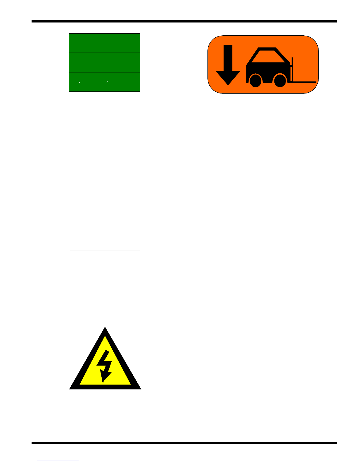
Lift Here: This point may be used as a lifting point.
If ignored, damage will occur to the laminator.
Refer to Figure 1.12.1 Label Placement
illustrates the location of each of these labels.
Safety Instructions: Read this label first before all
else!
Electrical Shock: Live voltage present. Exercise
extreme caution. You may be electrocuted!
© GBC Films Group February 2001
Page 1 - 15
Page 27
Safety Orca III/ Orca III T Operation and Maintenance Manual
y
p
y
p
g
p
g
y
p
g
y
pp
g
g
p
g p
g
p
pap
p
p
y
g
y
y
g
g
y
Figure 1.12.1 Label placement
WARNING
!
ACHTUNG
!
MISE EN GARDE
!
Crush and burn
hazard. Stay clear
of mo ving rolle r s.
Stop machine and
raise roll before
cleaning.
( Back of cabinet )
( x 2 in re ar )
WARNING
!
ACHTUNG
!
MISE EN GARDE
!
Moving parts can
crush and cu t.
( Left side frame )
!
!
!
WARNING
ACHTUNG
MISE EN GARDE
!
DANGER
!
GEFAHR
HAZARDOUS
VOLTAGE
To be serviced only
by trained and
authorized personnel.
Lockout power before
servicing
( Front of cabinet
WARNING
!
ACHTUNG
!
MISE EN GARDE
!
Crush and burn
hazard. Stay clear
of mo ving rolle r s.
Stop machine and
raise roll before
cleaning.
( Right sid e frame )
( Front of cabinet )
( x 2 in front )
WARNING
!
ACHTUNG
!
MISE EN GARDE
!
Crush and burn
hazard. Stay clear
of mo ving rolle r s.
Stop machine and
raise roll before
cleaning.
( Left side frame )
( Front of cabinet )
Crush and burn
hazard. Stay clear
of mo ving rolle r s.
Stop machine and
raise roll before
cleaning.
( Ba c k o f c abinet )
WARNING
!
III
A
C
R
O
Pro - Tech
C
B
G
ACHTUNG
!
MISE EN GARDE
!
Carefully read Operator's
Manual before handlin
this machine. Observe
instructions and safet
rules when operating.
( Ba c k o f c abinet )
SAFETY
INSTRUCTIONS
SICHERHEITSRICHTLINIEN
CONSIGNES DE
SECURITE
1. Read and understand the Operation
Manualan d a ll safe t
labels before
o
erating this machine.
a trained person is to be
2. Onl
ermitte d to operate this machine.
Trainin
should include instruction
in o
eration under normal conditions
and emer
ency situations.
3. This machine is to be servic e d o nl
by trained and authorized personnel.
Follow lockout
rocedures b e fore
.
servicin
4. Never reach into the machine for an
reason unless the machine is at a
COMPLETE STOP.
ed in
5. Never leave the machine sto
such a manner that another worker can
start the machine w hile you are workin
on or within the m achine.
6. Never change or de fe at the function of
electrical interlocks or other machine
" shutdown " switches.
7. Befor e sta rtin
this machine, che ck that:
ersons are clear of the machine.
- All
- No maintena nce w ork is bein
erformed
on the ma chine .
uards are in place.
-All
-All
arent rolls are w e ll ch ucke d in the
unwind stands.
er scraps,
- The machin e is free of
wra
s and jams.
otential hazard of entaglement
8. There is
item s such as
in this machine ca used b
lon
hair, loose clothing, and jewelry.
our clothing and hair fit
Make sure
to your body and that all jewelry,
closel
rin
s and watches are removed.
Front of cabinet
Page 1 - 16
© GBC Films Group February 2001
Page 28

2.0 Warranty
GBC Films Group warrants the equipment sold
is free from defects in material and workmanship for a
period of one ( 1 ) year parts and 90 days labor from
the date of installation. This warranty is the only warranty
made by GBC Films Group and con not be modified or
amended.
GBC Films Group’s sole and exclusive
liability and the customer’s sole and exclusive
remedy under this warranty shall be, at GBC Films
Group’s option, to repair or replace any such
defective part or product. These remedies are only
available if GBC Films Group’s examination of the
product discloses to GBC Films Group’ s satisfaction
that such defects actually exist and were not caused
by misuse, neglect, attempt to repair , unauthorized
alteration or modification, incorrect line voltage, fire,
accident, flood, or other hazard.
WarrantyOrca III/ Orca III T Operation and Maintenance Manual
CAUTION
Unauthorized customer alterations will
void this warranty.
THE WARRANTY MADE HEREIN IS IN
LIEU OF ALL OTHER WARRANTIES,
EXPRESS OR IMPLIED, INCLUDING
ANY WARRANTY OR
MERCHANTABILITY OR FITNESS
FOR A PARTICULAR PURPOSE. GBC
PRO-TECH WILL NOT BE LIABLE
FOR PROPERTY DAMAGE OR
PERSONAL INJURY ( UNLESS
PRIMARILY CAUSED BY ITS
NEGLIGENCE ), LOSS OF PROFIT OR
OTHER INCIDENTAL OR
CONSEQUENTIAL DAMAGES
ARISING OUT OF THE USE OR
INABILITY TO USE THE EQUIPMENT.
2.1 Limited Warranty
This warranty specifically does not cover damage
to the laminating rollers caused by knives, razor blades,
other sharp objects, failure caused by adhesives or
improper use of the machine. Warranty repair or
replacement does not extend the warranty beyond the
initial one year period from the date of delivery .
© GBC Films Group February 2001
2.2 Exclusions to the
Warranty
This warranty specifically does not
cover;
1. Damage to the laminating rollers caused by knives,
razor blades, other sharp objects or failure caused
by adhesives.
Page 2 - 1
Page 29

Warranty Orca III/ Orca III T Operation and Maintenance Manual
2. Damage to the machine caused by lifting, tilting and/
or any attempt to position the machine other than
rolling on the installed castors on even surfaces.
3. Improper use of the machine.
4. Damage due from unqualified person(s) servicing the
machine.
Qualified
• Any engineer that has experience with electrical
and mechanical design of lamination equipment.The
engineers should be fully aware of all aspects of safety
with regards to lamination equipment.
• Any commissioning or service engineer must be
of competent nature, trained and qualified to GBC ProT ech standards to fulfill that job. This person will have
completed and passed the full service training course from
GBC Pro-T ech.
• Any GBC T echnician, GBC Specialist, and / or
GBC Pro-T ech Technician that has been through the GBC
Pro-T ech service training course.
Page 2 - 2
© GBC Films Group February 2001
Page 30

3.0 Specifications
Specifications provide all of the technical data for
the Orca III/ Orca III T Laminator.
3.1 General
SpecificationsOrca III/ Orca III T Operation and Maintenance Manual
Description:
Features:
• High level, wide format color finisher for the sheet fed
ink jet and electrostatic market. The Orca III/ Orca
III T is a self standing, bi-directional laminator/
transfer machine.
• Three swing out film unwinds ( 1 upper , 2 lower )
• One swing out print unwind
• Four rewinds ( 1 upper front, 1 upper rear , 1 lower
front and 1 lower rear )
• Infeed and oufeed tables
• Footswitch
• Bi-directional operations
• Four emergency stop push buttons ( E-STOPs )
• Front and rear emergency cables ( E-CABLEs )
• Photo-electric nip sensors ( PHOTO-EYEs )
• Independent top and bottom heater units
• T wo fixed web tension idlers ( 1 lower , 1 upper )
• Five repositionable web idlers
• T wo removable slitter idlers ( 1 front, 1 rear )
• T wo removable table idlers
• No slip core grip chucks ( 2 per unwind )
• Speed ranges from 0 to 15 ft/min ( 0 - 4.6 m/min )
• Pneumatic air cylinders for roller nip control
• T wo removable cooling ducts ( 1 upper , 1 lower )
• Multiple thermal protection circuitry
• Infeed and outfeed slitters
Applications:
© GBC Films Group February 2001
• Single sided lamination
• Encapsulation
• Mounting
• Decaling
• Transfer
Page 3 - 1
Page 31

Specifications Orca III/ Orca III T Operation and Maintenance Manual
3.2 Consumables
Film types:
Film diameters:
Core size:
Film widths:
• Pressure sensitive laminates
• Pressure sensitive adhesives
• Low melt laminates
• Thermal laminates
• Thermal adhesives
• Up to a 10 in. roll diameter ( 25.4 cm )
• 3 in. core standard ( 7.62 cm )
• 58 in. maximum pressure sensitive ( 147 cm )
• 55 in. maximum thermal ( 140 cm )
Paper widths:
Mounting thickness:
Safety:
Rewind tubes:
• 55 in. maximum paper width ( 140 cm )
• Up to 1 in. thick ( 2.54 cm ) either direction
• Designed to UL / CSA / CE safety standards
• 3 in. diameter x 66-3/8 in. length (7.62 x 168.59 cm)
Page 3 - 2
© GBC Films Group February 2001
Page 32

3.3 Function
SpecificationsOrca III/ Orca III T Operation and Maintenance Manual
Speed:
Motor:
Heating capabilities:
Controls:
Heater controls:
• 0 - 15 ft / min ( 0 - 4.6 m / min )
• 1/4 horse power drive motor
• Bi-directional D.C. motor
• 32oF - 290oF ( 0oC - 143oC )
• Front control panel
• Rear control panel
• Footswitch
• Independent Cal 3200 control units
Rollers:
Roll design: Orca III
Orca III T
• Heat capable upper and lower main rollers
• Driven lower main roller
• Free spinning upper main roller
• Pneumatic controlled lower pull roller
• Free spinning upper pull roller
• High release silicone rollers
• T eflon coated ( Upper roller only )
• High release silicone rollers
© GBC Films Group February 2001
Page 3 - 3
Page 33

Specifications Orca III/ Orca III T Operation and Maintenance Manual
3.4 Electrical
United States and Canada:
Europe:
B.T .U. output:
Heater wattages:
Amperage draw:
• 230 - 240 V AC, 50/60 Hz, single phase, 55 amps.
• 230 - 240 VAC, Wye 3 phase, 25 amps/ phase
• 37,532 B.T .U. / hour
• 5500 watts per heater
• No heat, motor only : 1 - 3 amps
• T op heat and motor : 20 - 23 amps
• Both heat and motor : 40 - 43 amps
D/C voltage used:
A/C voltage used:
• 24 vdc
• 230 vac ( minimum )
Page 3 - 4
© GBC Films Group February 2001
Page 34

3.5 Dimensions
Weight:
SpecificationsOrca III/ Orca III T Operation and Maintenance Manual
Crated:
Uncrated:
Dimensions
Crated:
Uncrated
• 2800 lbs. ( 1270 kg. )
• 2300 lbs. ( 1043 kg. )
• 75 in. (H) x 43 in. (W) x 102 in. (L)
( 191 cm (H) x 109 cm (W) x 259 cm (L) )
• 60 in. (H) x 33 in. (W) x 82 in. (L)
( 152 cm (H) x 84 cm (W) x 208 cm (L) )
Refer to Figure 3.5.1
Nip Height:
• 35 1/5 in. ( 90 cm )
© GBC Films Group February 2001
Page 3 - 5
Page 35

Specifications Orca III/ Orca III T Operation and Maintenance Manual
Figure 3.5.1 Dimensions ( both machines have the same dimensions )
82 in.
( 208 cm )
60 in.
( 152 cm )
III
A
C
R
O
Pro - Tech
GBC
33 in.
( 84 c m )
Page 3 - 6
2 in.
( 5.1 cm )
© GBC Films Group February 2001
Page 36

InstallationOrca III/ Orca III T Operation and Maintenance Manual
4.0 Installation
GBC Films Group is committed to a program of
ongoing product improvement. As a result, we are
providing these instructions so you can insure that your
new Orca III/ Orca III T Laminator is properly and
securely unpacked, moved, and installed.
Before an Orca III/ Orca III T Laminator can be
installed, there are a few requirements that must be met.
Make certain that each of the requirements listed in the
following pre-installation checklist are met before beginning
installation.
CAUTION
Is the environment appropriate for the laminator?
The laminator requires a clean, dust and vapor
free environment to operate properly . It must not
be located where there is air blowing directly on
the machine
Have you contacted a certified electrician to both
wire the laminator and ensure that adequate power
is being supplied, having the appropriate capacity ,
over current protection and safety lockouts are
available?
WARNING
The operating environment must be free of
dust, flammable liquids and vapors. You can
be injured by inhaling chemical vapors.
Failure to follow the pre-installation check
list can result in damage to the laminator.
4.1 Pre-installation
Are doorways and hallways wide enough for the
laminator to be moved to the installation site?
Is there ample room for the laminator?
A work area must be established that allows for
operation in both the front and rear of the
laminator and provides space for efficient material
flow . Figure 4.1.1 illustrates a typical machine
area layout.
WARNING
Vapor build up or stored flammable
liquids can cause a fire. Excessive
dust can damage the laminator.
CAUTION
Do not locate the laminator where air is
blowing directly on the machine. The air
flow can cool the rolls unevenly and result
in poor output quality.
© GBC Films Group February 2001
Page 4 - 1
Page 37

Installation Orca III/ Orca III T Operation and Maintenance Manual
The laminator requires 230 to 240 vac, 50/ 60
Hz, 55 amps. Or, in Europe only, 3-N phase,
240 vac, 32 amps/ phase.
WARNING
Th e Orca III/ Orca III T Lam in ator is a
large and h eav y p iece of eq u ipm en t. It is
necessary to employ L IC E N S E D RIGG E R S
O N LY to move th e la mina tor . It is n ot
designed to be tipped up or sideways in any
way. Such action disturbs the exact
alignme n t o f th e ro llin g p a r ts o f the m ac h in e
and requires extensive re-alignment. You
can b e cru shed o r seriou sly injured .
For instructions on how to connect power,
proceed to 4.7 Electrical connection in this section.
Page 4 - 2
© GBC Films Group February 2001
Page 38

Figure 4.1.1 Suggested Floor Layout
InstallationOrca III/ Orca III T Operation and Maintenance Manual
4 ft. x 6 ft.
20 ft.
( 508 ) cm
Air compressor
or air line drop
Electrical cord
drop
8 ft 8 in
( 220 cm )
(101.6 x 152 cm)
W ork table on wheels
Back
3 ft
( 91 c m )
Front
© GBC Films Group February 2001
8 ft 8 in
( 220 cm )
4 ft. x 6 ft.
(101.6 x 152 cm)
W ork table on wheels
13 ft
( 330 cm )
Page 4 - 3
Page 39

Installation Orca III/ Orca III T Operation and Maintenance Manual
4.2 Know your machine
Before performing any procedure within this
manual, it is recommended that you take time to know
the parts of your new machine.
Figure 4.2.1 The laminator
Control side
Rear
Figure 4.2.3 Front view
Front
control
panel
Front lower unwind
Rewind brake
Cardboard
rew in d t ub e
Mid d le u nwind
Motor
E-STOP
E-CABLE
Leveling
pad
Front
Figure 4.2.2 Top view
Rear table ( option )
Pu ll ro lle rs
Main ro llers
Upper unwind
Table idler
ORCA
III
Pro -
Tech
GBC
Drive side
Upper unwind brake
Rear table
bracket
Main ro ller
shim dial
Figure 4.2.4 Rear view
E-STOP
Castor
Core chuck
Rear lower unwind
Pu ll ro lle r s h im dia ls
Core support
Permanent Idler
Tie bar
Unwind saddle
Rear
control
panel
Circuit
breaker
Large table
Small t a b le
Page 4 - 4
© GBC Films Group February 2001
Page 40

InstallationOrca III/ Orca III T Operation and Maintenance Manual
4.3 Unpacking
INFORMATION
ALL SHIPMENTS ARE EX-WORKS.
dock, title passes to the buyer. Please review
your insurance coverage prior to shipment,
as you are responsible for all subsequent
freight charges and risks.
INFORMATION
Before signing the Bill of Lading, you
should be sure to inspect the crate
and / or pallet for signs of damage or
missing items; if applicable, make
note of this on the Bill of Lading.
At our
With regards to your shipping method, use one of
the following procedures described to safely and properly
unwrap / uncrate your laminator .
4.4 Shrink Wrapped
a) Inspect the machine for any obvious shipping
damages upon receipt.
b) Carefully unwrap the shrink wrap from around
the laminator .
CAUTION
INFORMATION
Depending on the destination and customer
preference, your machine may be shipped in
various ways. The laminator may arrive
shrink wrapped or in a plywood crate on a
skid. Please follow the unpacking procedure
that pertains to your method of shipment.
WARNING
Do not attempt to move the laminator across
The unpacking process requires at least two
people. You can be severely injured, crushed
or cause damage to the laminator.
Do not use a knife or other sharp object to
remove the shrink wrap from around the
laminator. You can cause irreparable
damage to the rollers.
c) With another person, carefully wheel your Orca
III/ Orca III T Laminator to the installation site.
WARNING
anything other than a flat level surface
without trained and qualified riggers. You
can be crushed or seriously injured.
© GBC Films Group February 2001
Page 4 - 5
Page 41

Installation Orca III/ Orca III T Operation and Maintenance Manual
4.5 Crated
WARNING
Th e Orca III/ Orca III T Lam in ator is a
large and h eav y p iece of eq u ipm en t. It is
necessary to employ L IC E N S E D RIGG E R S
O N LY to move th e la mina tor . It is n ot
designed to be tipped up or sideways in any
way. Such action disturbs the exact
alignme n t o f th e ro llin g p a r ts o f the m ac h in e
and requires extensive re-alignment. You
can b e cru shed o r seriou sly injured .
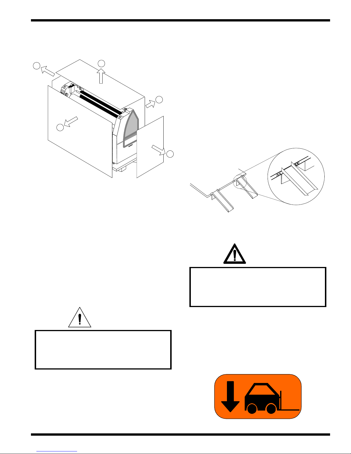
4.5.1 Uncrate the laminator
a) Remove the top of the crate and then the sides
in the order shown in Figure 4.5.1
CAUTION
Do not allow the top to fall into the crate. It
can damage the laminator.
INFORMATION
GBC Film Group's warranty does not
cover malfunction of the equipment due to
mishandling and / or tipping. GBC Films
Group bears no responsibility for personal
injury or damage due to moving the
laminator improperly.
Tools required
• # 2 Phillips head screwdriver
• 7/8” open end wrench or adjustable wrench
• Crow bar
• A second person
INFORMATION
Do not put packing screws on the floor.
They can cause problems when trying to roll
the laminator into position or you can
become injured if stepped on.
CAUTION
A second person must support the side
labeled 5 in Figure 4.5.1 It can fall and
damage the laminator or cause harm to you
and others.
Page 4 - 6
© GBC Films Group February 2001
Page 42
InstallationOrca III/ Orca III T Operation and Maintenance Manual
Figure 4.5.1 Disassembling of the crate
3
Remove This Side
4
1
5
III
A
C
R
O
h
c
e
T
-
o
r
P
C
B
G
4.5.3 Moving the laminator
a) Have the laminator removed off of the skid one of
two methods:
1) Rolled off the skid and placed on the floor by
licensed riggers using the included ramps. The
ramps must be secured utilizing screws
removed from the disassembled crate.
2
4.5.2 The shrink wrap
a) Gently unwrap the shrink wrap from around the
laminator.
CAUTION
Do not use a knife or other sharp object to
remove the shrink wrap from around the
laminator. You can cause irreparable
damage to the rollers.
WARNING
Do not attempt to use the ramps if they are
not secured to the pallet. Ensure the pallet is
on a flat even surface before attempting to
roll the machine off.
2) Lifted off of the skid with a forklift by positioning
the forks where indicated by fork lift decals
located on the tie bars on the machine.
b) Move all packing materials to a safe distance.
© GBC Films Group February 2001
Page 4 - 7
Page 43

Installation Orca III/ Orca III T Operation and Maintenance Manual
b) Remove any plastic strapping and/or packing
paper taped to the rollers.
CAUTION
Do not use a knife or other sharp object to
remove the shrink wrap from around the
laminator. You can cause irreparable
damage to the rollers.
c) Remove all packing materials to a safe distance
from the laminator and dispose of properly .
e) Consider the following when determining where
to locate your machine;
WARNING
Th e op erating en viron m en t m ust b e free of
dust, flammable liquids and vapors. You can
be injured by inhaling chemical vapors.
WARNING
Vapor build up or stored flammable liquids
can cause a fire. Excessive dust can damage
the la mina tor .
INFORMATION
Ab out recycling: The crate compon ents can
be reused for shipping the laminator again
or can be disassembled and the wood and
screws recycled. Th e sh rink wrap is not
recyclable, so it must be d iscarded.
d) Use two people to carefully roll the laminator to
the desired location.
WARNING
Do not attempt to m o v e th e la minato r a c ro ss
anything other than a flat level surface
without trained and qualified riggers. You
can b e cru shed o r seriou sly injured .
CAUTION
Do n o t locate the lam ina tor w h ere air is
blow ing directly on the machine. Th e a ir
flow can cool th e rolls un even ly an d resu lt in
poor quality output.
INFORMATION
En su re sufficien t space f or op en ing of the
cabinets for maintenance and servicing.
Page 4 - 8
© GBC Films Group February 2001
Page 44

InstallationOrca III/ Orca III T Operation and Maintenance Manual
4.6 Accessory pack
Once the Orca III/ Orca III T Laminator has been
unpacked and moved into final position, open the accessory
pack and verify the contents.
Accessory Pack contents
• (1) 1/4 T-handle allen wrench - 475-210
• (1) Set SAE allen wrenches - 475-230
• (1) Modified 1/4 allen wrench - 485-001
• (1) Zippy knife - 475-620
• (1) Rubber cement pad - 930320
• (1) Roll masking tape - 475-000
• (1) T ape measure - 475-100
• (1) Operators manual - 930-062
• (1) Main power strain relief - 175-201
• (1) Unwind/ rewind brake - 625-006
• (1) Unwind/ rewind brake pad - 375-000
• (1) Air hose with fittings - 360-000
• (1) Coupling, 1/4, air fitting - 333-000
• (4) Polyurethane O-rings - 480-005
• (4) Fuses, SB, 3.0AG - 186-200
• (4) Leveling pads - 470-100
4.7 Electrical Connection
The Orca III/ Orca III T laminator requires 220
~ 240 VAC electrical power for proper operation. The
power supply may be either single phase or three phase
(five wire or four wire). For single-phase power, a 55
amp service is required and for three-phase power, 25
amps per phase is required.
The Orca III/ Orca III T requires the electrical
power cord to be wired directly to the line terminal block
located within the control side cabinet.
Before the machine is installed, a qualified
electrician must route the proper wiring to the location
where the machine will be stationed. The machine then
can be connected to the power supply by a qualified
electrician following one of the three instructions listed
below .
ELECTRICAL
SHOCK
CAUTION
Exer cise extrem e cau tion when rem o ving
the slitter assemblies or th e rotary blad es.
Sharp knife can cut you!
• (1) Circular blade - 475-001
• (4) Slitter assemblies - 001-122
If you are missing any of the items listed above,
contact your local service technician or sales
representative.
© GBC Films Group February 2001
Only a qualified electrician should connect
power to the laminator. You can be severely
shocked, electrocuted or cause a fire if
power is improperly applied.
ELECTRICAL
SHOCK
Do not allo w anyth in g to r est o n t h e
pow e r cord . Do n ot locate the cord where
people can walk on it. Y ou or others can
be severely sh oc ked , electrocuted or
cause a fire.
Page 4 - 9
Page 45

Installation Orca III/ Orca III T Operation and Maintenance Manual
g
g
g
4.7.1 Preparation
a) Ensure the power at the junction box is in the
OFF position. Use a voltage meter to verify.
b) Open the control side cabinet by removing the
four hex button head screws with a 5/32 in. allen
wrench.
Bolts
Figure 4.7.1 Single phase ( 3 wire )
Hot LegHot Leg
Blue Wires
Ground
Gound
Wire
Red W ires
L 6 L 4 L 2
L 5 L 3 L 1
Figure 4.7.2 Delta three phase ( 4 wire )
Cut here
Jumper
Bar
Blue WiresRed Wires
L 6 L 4 L 2
L 5 L3 L 1
34
32
9
8
10
24
7
31 11
11
6521 22
1
2
A1A2
14
3
12
4
34
32
9
10
7824
31 11
11
652122
1
A1A2
14
34
31 11
11
1
A1A2
14
34
3111
11
1
A1A2
14
34
31 11
11
1
A1A2
14
34
31 11
11
1
A1A2
14
34
3111
11
1
A1A2
14
F+P2P3 I1P1 L1F- L2A+ A-
2
12
4
3
3278
9
10
24
6521 22
2
12
4
3
32
8
9
10
24
7
6521 22
2
12
4
3
4
1
O
I
32
U
8
9
10
N
T
24
7
P
P
6521 22
U
U
3
2
T
T
2
4
3
12
32
9
8
10
24
7
21 22
6
5
O
4
1
2
I
12
4
U
3
N
T
32
8
9
P
P
10
24
7
U
U
3
2
T
T
6521 22
2
12
4
3
+ -
Jumper bars
Line terminal block
Gound
wire
St r ain relief
c) Remove the power cable strain relief ( 175-201 )
from the accessory box and install it at the lower
rear hole of the control side cabinet.
d) Connect the power cord to the line terminal
block. Refer to the correct Figure for your
connection. Jumper bars may require removing
or cutting.
Terminal
connecter
Jumper Bars
Position
Hot Le
Red Wires
L 6 L 4 L 2
L 5 L 3 L 1
Hot Le
Blue Wires
Hot Le
Ground
Gound
Wire
Jumper Wire
Figure 4.7.3 Wye three phase ( 5 wire )
Blue Wires
Neutral Leg
Ground
Gound
Wire
Remove
Jumper Bars
Hot Leg
Red W ires
L 6 L 4 L 2
Hot Leg
L 5 L 3 L1
Hot Leg
Page 4 - 10
© GBC Films Group February 2001
Page 46

InstallationOrca III/ Orca III T Operation and Maintenance Manual
e) Turn the junction box power to the ON
position.
f) V erify line voltage with regards to the type of
power being supplied to the laminator at the line
terminal block.
ELECTRICAL
SHOCK
On ly a qu alified electrician sho u ld verify
the voltage. Yo u can b e severely sh ock ed ,
electrocuted or ca use a f ire.
g) Close the control side cabinet and secure with the
factory bolts.
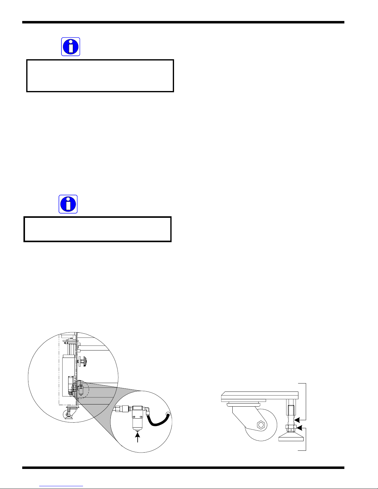
4.8 Air connection
The laminator requires filtered air at 2 cubic feet
per minute (cfm), 50 liters/minute at a pressure of 100
pounds per square inch (psi) (700 kPa). The air supply
must be clean (free of dirt) and dry . Moisture causes
corrosion and particles can block the pneumatic controls.
Either problem can cause the laminator to malfunction.
It is the customer’s responsibility to provide
appropriate filters and water traps for the air hose before
the air is routed to the laminator . GBC suggests that the
best approach to the air requirement is to provide a
dedicated small compressor for the laminator . A standard
light duty 1/2 to 3/4 horse power (1 kW) electric air
compressor with 1.5 to 2.5 cfm output with a 5 gallon
(20 liter) storage tank is appropriate.
WARNING
Do n o t opera te the m a ch ine w ith th e
control side or drive side cabinet
in th e o p en p o s itio n .
ELECTRICAL
SHOCK
Do not op er a te th e la m inator if th e p ower
cord is damaged or frayed. You can be
severely shock ed , electrocuted o r cau se a
fire. Contact a qu alified electrician to
replace the cor d.
a) Once a quick disconnect is attached to the end of
the hose from the compressor, connect the air to
the air filter located on the machine.
Air filter
Quick-
disconnect
© GBC Films Group February 2001
Page 4 - 11
Page 47
Installation Orca III/ Orca III T Operation and Maintenance Manual
4.9 Installing levelers
IN F OR MATIO N
Th e u pp er m a in roller an d the u p per p u ll
rolle r s h o u ld b e in th e ra is ed p o s itio n .
c) Set the air in pressure from the source to 100
pounds per square inch (psi) (700 kPa).
IN FO RMAT ION
Release moisture from th e air filter on a
week ly b asis or as n eede d.
Leveling of the machine is a customer option. If
you choose not to level the laminator and you encounter
output problems, please level the machine and try your
application again before calling for technical support.
Resting the laminator on the leveling pads will prevent the
machine from rolling during set up, operation or servicing.
Tools required
• ( 1 ) 1/2 in. open end wrench
• ( 1 ) 7/8 in. open end wrench
• (4) leveling pads
( from the accessory pack )
d) Press up on the pin located at the very bottom of
the air filter to release moisture in the trap.
a) Be sure that the machine is placed where you
want it to rest.
b) Secure the four leveling pads onto the four foot
bolts.
c) Use the 1/2 in. wrench on the foot bolt and the
7/8 in. wrench on the leveling pads and tighten
them together.
1/2 in . wre n c h
Page 4 - 12
Press here
7/8 in . wre n c h
© GBC Films Group February 2001
Page 48

InstallationOrca III/ Orca III T Operation and Maintenance Manual
4.10 Leveling
Leveling of the machine is an important step in
assuring that the equipment will run at it’s optimal speed
and capabilities with little adjustments as possible.
a) Use the foot bolt to raise/ lower the machine so
that the bubble in the leveler is centered.
Center the bubble
c) Place the leveler on the control side frame, not
the top of the cabinet, and level the machine from
front to rear.
Place level here
III
A
C
R
O
GBC
h
c
e
T
-
o
r
P
1/2 in. w rench
b) Place the leveler on the lower front tie bar and
level the machine from left to right.
e) Do the same for the drive side.
Pla c e le v e l h e re
III
A
C
R
O
GBC
Pro - T
ech
Place level here
© GBC Films Group February 2001
f) Place the leveler on the lower rear tie bar and
III
A
C
R
O
Pro - Tech
GBC
level the machine from left to right.
g) V erify all sides to confirm that the machine is level.
Page 4 - 13
Page 49

Installation Orca III/ Orca III T Operation and Maintenance Manual
4.11 Unwind/ rewind brake
The unwind/ rewind brake is used when you
require a rewind tube to be undriven ( “free spinning” ) by
the rewind drive puck. The brake pad is for the unwind/
rewind brake. The pad is also used to protect the blades
when they are in the rest positions.
a) Remove unwind/ rewind brake and the brake
pad from the accessory pack.
b) Place the adheisve side of the large ring pad on
the unwind/ rewind brake. The brake pad will
overhang the brake slighlty .
d) Save the center piece from the brake pad for use
later in Section 4.12 Slitter assemblies.
e) Remove the rewind tube.
f) Remove the O-Ring from the rewind drive puck.
Rewind tube
O-Ring
Rewind drive puck
CAUTION
Cau tion sho uld alw a ys b e ex ercised
when using a knife .
Sharp knife can cut you!
c) Use a knife or razor to trim the excess brake
pad from the brake.
Brake pad
Trim ex ce s s
g) Position the unwind/ rewind brake over the rewind
drive puck with the brake pad facing the side
frame.
Rewind tube
Brake
Rewind drive puck
h) Replace the rewind tube. The unwind/ rewind
brake keeps the rewind drive puck from making
contact with the rewind tube enabling the rewind
tube to turn in either direction regardless of motor
direction.
Page 4 - 14
© GBC Films Group February 2001
Page 50

InstallationOrca III/ Orca III T Operation and Maintenance Manual
4.12 Slitter assemblies
CAUTION
Exer cise extrem e cau tion when w o rkin g
w ith th e slitter ass em b lie s.
SHARP KNIFE CAN CUT YOU!
The slitter assemblies provide a method of
trimming the left and right sides of the print and trimming
of the left and right sides of the finished product when
used in a roll to roll application.
b) Place the pieces ( 1,2,3 & 4 ) on the slitter idler
stand offs as illustrated below .
Stand offs
Pieces of cut pad
c) Use the 1/4 allen wrnech to secure two slitter
assemblies to the front tie bar below the slitter
idler .
Slitter
assembly
Tools required
• ( 1 ) Modified 1/4 in. allen wrench
( from the accessory pack )
• (1) 1/4 in. allen wrench
( from the allen wrench set in the accessory pack)
• The center piece from the brake pad.
( step d) in Section 4.11 Unwind/r ewind brake)
a) Cut the center piece of the brake pad as illustarted
below .
Slitter idle r
Tie bar
d) Rest one on each side of the slitter idler so the
blade is resting on the pad of the standoffs.
Pad
12
4
3
© GBC Films Group February 2001
CAUTION
Neve r leave th e slitter assemblies u nsecu red .
Alw a ys secu re in th e pro p er rest po sition.
Un secu red b lad e can cu t you !
Page 4 - 15
Page 51
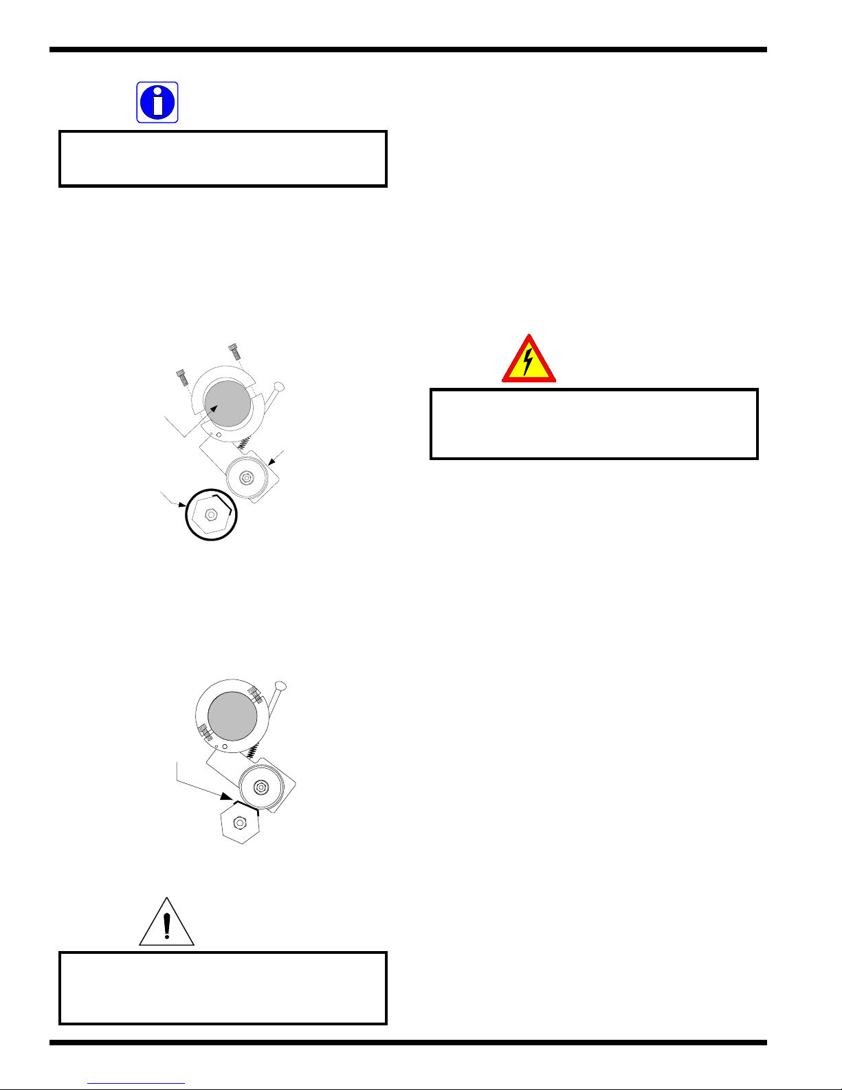
Installation Orca III/ Orca III T Operation and Maintenance Manual
4.13 Calibrations
IN F O R M A T IO N
Th e rear slitter assem blies req uire the u se
of the modified 1/4 in. allen w rench
by a qualified GBC technician before the machine is to be
operated. These calibrations may not be performed by
the operator . Improper calibrations can result in poor
lamination output.
e) Use the modified 1/4 allen wrench to secure two
slitter assemblies to the rear tie bar above the slitter
idler .
The following calibrations should be performed
ELECTRICAL
SHOCK
Tie bar
Slitter
assembly
Slit te r id le r
f) Rest one on each side of the slitter idler so the
blade is resting on the pad of the standoffs.
Pad
Th ese calibration s req uire th e lam ina tor
to be po w ered u p w h ile the cabin ets
are open ed .
a) The main roller nip is to be calibrated.
b) The pull roller nip is to be calibrated.
c) Front and rear photo-eyes are to be calibrated.
d) The drive chains are to be checked and
tensioned if necessary .
CAUTION
Neve r leave th e slitter assemblies u nsecu red .
Alw a ys secu re in th e pro p er rest po sition.
Un secu red b lad e can cu t you !
Page 4 - 16
e) Air rate on both set of rollers are to be checked.
f) Safety check and control panel operation checks
are to be performed.
© GBC Films Group February 2001
Page 52

Orca III/ Orca III T Operation and Maintenance Manual
Operations
5.0 Operations
WARNING
Do not wear ties, loose fit clothing or
dangling jewelry while operating or
servicing the laminator. These items can get
caught in the nip and choke you or you can
be crushed or burned.
This section discusses power on/off, the
function of the front control panel, the function of the
rear control panel, how to set the temperature, what
to do in case of an emergency, film loading and
unloading, how to set the main roller nip, how to set
the pull roller nip, unwind brake tension, rewind brake
tension and how to properly shutdown the laminator.
5.1 Power on/ off
ELECTRICAL
SHOCK
Do n o t turn p o w er on if the p ower cord
is damaged or frayed. You can be
severely shocked, electrocuted or
cause a fire. Contact a qualified
electrician to replace the cord .
a) Ensure power from the junction box on the
wall is in the “ON” position.
b) Physically check to confirm that all four E-
STOPs are in the unlatched position.
WARNING
W h en the lam in ator rollers are in
motion, keep hands and fingers
away from the nip of the rollers.
You may be CRUSHED or BURNED!
IN FO RMAT ION
Th e la minato r will only turn o n if
all E-ST OPs are un latched .
© GBC Films Group February 2001
c) Turn the circuit breaker on the machine to
the “ON” position.
Off
On
Page 5 - 1
Page 53

Operations
Orca III/ Orca III T Operation and Maintenance Manual
5.2 Front control panel
The control panel on the Orca III/ Orca III T
Laminator is located at the front operating position of
the machine on the left ( control ) side cabinet.
The front control panel enables the operator
to control linear footage/ rate display, motor speed,
motor direction, motor auto/ stop, top temperature,
bottom temperature, main roller pressure and main
roller up/ down.
( 1 ) Speed Readout: Displays the speed of the
machine and the linear footage total. When the “ R” is
displayed, the readout is displaying the rate. When only
a numeric value is displayed, the readout is displaying
linear footage.
( 2 )Speed Control Dial: Adjusts the speed of the
motor from zero to a maximum speed of 15 feet per
minute ( 4.5 meters per minute ). Turn the dial
clockwise to increase speed and counter clockwise to
reduce speed.
AUTO
STOP
SPEED
FW D
REV
( 3 )Forward / Reverse Switch: determines the motor
direction. In the FWD position, the motor will turn in
a forward motion. In the REV position, the motor
will turn in a reverse direction. In the center position,
the motor will not turn at all.
AUTO
STOP
SPEED
FWD
REV
• The “ SEL “ button will toggle the unit between the
two choices of readouts. ( speed rate or linear
footage total )
• The “ RST “ button will reset the linear footage total
whether the display is showing rate or linear footage
total.
R 0 .0
SEL
RST
IN FO RMAT ION
Th e cen ter pos ition is to preven t jam m in g
of the m otor when ch an gin g d irections
( 4 ) Auto / Stop Switch: This switch will engage the
motor circuitry and disengage the motor circuitry . This
is a momentary switch for latching purposes so that
two separate switches can serve the same function.
See Rear Control Panel for the other location of this
switch.
FW D
AUTO
Page 5 - 2
SPEED
REV
STOP
© GBC Films Group February 2001
Page 54

Orca III/ Orca III T Operation and Maintenance Manual
Operations
( 5 ) Temperature Control Unit ( Top ): This unit is
used to set the desired heating temperature of the top
main roller . The display can be programmed to show
o
F or oC. Maximum temperature is 290 oF ( 143 oC ).
32
CAL 3200
32
CAL 3200
( 6 ) Temperature Control Unit ( Bottom ): This
unit is used to set the desired heating temperature of
the bottom main roller. The display can be programmed
to show oF or oC. Maximum temperature is 290 oF
( 143 oC ).
( 8 ) Bottom Heater on / off Switch: Turns the
temperature controller unit for the lower main roller
to on ( I ) or off ( O ).
TOP
HEAT
IN FO RMAT ION
Top and bottom temperature control units
on / o ff switche s must b e in th e ON ( I )
position to h eat either ro ller.
BOTTO M
32
CAL 3200
32
CAL 3200
( 7 ) Top Heater on / off Switch: Turns the
temperature controller unit for the upper main roller
to on ( I ) or off ( O ).
TOP
HEAT
BOTTO M
( 9 ) Main Roller Pressure Adjustment: Adjusts the
air pressure supplied to the main roller air cylinders.
Pull out on the knob to turn and push in on the knob
to lock down.
PRESSURE
50
40
P.S.I.
60
70
80
90
100
ROLL
ADJ
30
20
10
0
IN FO RMAT ION
IN FO RMAT ION
Top and bottom temperature control units
on / o ff switche s must b e in th e ON ( I )
position to h eat either ro ller.
© GBC Films Group February 2001
W h en d ecreasin g p ressu re, allow the
pressure g u age to dro p b elow the desired
value, then in crease p ressu re to th e set
pressure d esired . Th is allow s fo r a more
accura te pressu re read ing .
Page 5 - 3
Page 55

Operations
Orca III/ Orca III T Operation and Maintenance Manual
( 10 ) Main Roll Pressure Gauge: Displays the air
pressure supplied to the main roller air cylinders.
PRESSURE
50
40
P.S.I.
60
70
80
90
100
ROLLADJ
30
20
10
0
( 1 1 ) Main Roll up / down Switch: When pressed to
the down position, the upper main roller lowers. When
pressed to the up position, the upper main roller raises.
( 13 ) Fan Table ON/ OFF Switch: This switch
controls the optional vacuum table. When pressed to
the ( I ) position, the fans on the vacuum table turn on.
When pressed to the ( 0 ) position, the fans on the
vacuum table turn off.
MAIN POWE R
FAN TABLE
For a complete illustration of the front control panel,
refer to Figure 5.2.1 Front control panel on page
5-5.
PRESSURE
50
40
P.S.I.
60
70
80
90
100
ROLL
ADJ
30
20
10
0
( 12 ) Main Power Indicator Light: When
illuminated, there is electrical power going to the
machine.
M A IN P O W E R
FAN TABLE
Page 5 - 4
© GBC Films Group February 2001
Page 56

Orca III/ Orca III T Operation and Maintenance Manual
Figure 5.2.1 Front contr ol panel
PRO TECH ENG INE ERING DEFOR E S T W I. U.S.A. (608) 246 - 8844
Operations
3
2
R 0 .0
RST
SPEED
SEL
FW D
REV
MOTOR CONTROLS
32
CAL 3200
TOP BOTTO M
CAL 3200
1
AUTO
4
STOP
65
32
7
10
9
12
LAMINATOR ROLL CONTROLS
MA IN P O W ER
HEAT
PRESSURE
50
40
30
20
10
0
P.S.I.
60
70
80
90
100
8
ROLLADJ
11
FAN TABLE
13
© GBC Films Group February 2001
Page 5 - 5
Page 57

Operations
Orca III/ Orca III T Operation and Maintenance Manual
5.3 Rear control panel
The rear control panel enables the operator to
control the clutch operation, the upper pull roller
operation, the cooling fans and the motor auto/ stop.
( 1 ) Clutch pressure adjustment: Adjusts air pressure
supplied to the pneumatic clutch for the lower pull
roller. Pull out on the knob to turn and push in on the
knob to lock down.
– With a lower pressure supplied to the clutch,
the clutch slips more and the pull rolls pull with
less force.
– With a higher pressure supplied to the clutch,
the clutch slips less or not at all and the pull
rolls pull with a greater force.
( 2 ) Clutch Pressure Gauge: Displays the air pressure
supplied to the pneumatic clutch.
PRESSURE
50
40
30
20
10
0
ADJ
60
70
80
90
100
P.S.I.
( 3 ) Clutch on / off Switch: Engages or disengages
air flow to the pneumatic clutch driving the lower pull
roller. The lower pull roller is connected to the chain
drive system via a pneumatic clutch.
PRESSURE
50
40
30
20
10
0
ADJ
60
70
80
90
100
P.S.I.
IN FO RMAT ION
W h en d ecreasin g p ressu re, allow the
pressure g u age to dro p b elow the desired
value, then in crease p ressu re to th e set
pressure d esired . Th is allow s fo r a more
accura te pressu re read ing .
– When the clutch switch is on ( I ), the lower
pull roller is engaged with the chain drive
system and pulls more or less depending on
the clutch pressure adjustment setting.
– When the clutch is off ( 0 ), the clutch is in
the “free spin” state. The lower pull roll is
disengaged and will not respond to the motor
controls.
PRESSURE
50
40
30
20
10
0
ADJ
60
70
80
90
100
P.S.I.
Page 5 - 6
© GBC Films Group February 2001
Page 58

Orca III/ Orca III T Operation and Maintenance Manual
Operations
( 4 ) Pull Roller Pressure Adjustment: Adjusts air
pressure supplied to the pull roller air cylinders. Pull
out on the knob to turn and push in on the knob to
lock down.
PRESSURE
50
40
P.S.I.
60
70
80
80
90
100
ROLL
30
20
10
0
ADJ
IN FO RMAT ION
( 6 ) Pull Roller UP/ DOWN Switch: Signals the
solenoid air valve for the pull roller air cylinders to
shift to the appropriate position to either raise or lower
the upper pull roller.
PRESSURE
50
40
P.S.I.
60
70
80
80
90
100
ROLL
30
20
10
0
ADJ
IN FO RMAT ION
W h en d ecreasin g p ressu re, allow the
pressure g u age to dro p b elow the desired
value, then in crease p ressu re to th e set
pressure d esired . Th is allow s fo r a more
accura te pressu re read ing .
( 5 ) Pull Roll Pressure Gauge: Displays the air
pressure supplied to the pull roller air cylinders.
PRESSURE
50
40
P.S.I.
60
70
80
80
90
100
ROLL
30
20
10
0
ADJ
W hen an emergency stop feature is activated
an d th e main r o ll is in the up p o si tio n , th e
pu ll r o ll will on ly s ta y in the u p positio n
until the em ergen cy stop fea ture is
deactivated.
( 7 ) Cooling Fans ON/ OFF Switch: Turns the
cooling fans on or off. The cooling fans only operate
when the motor circuit is engaged.
COOLING FANS
AUTO
© GBC Films Group February 2001
STOP
( Read note on next page. )
Page 5 - 7
Page 59

Operations
IN FORMATION
Th e m o tor m u st be en ga ged fo r the co oling
fans to t u r n o n. If th e fa n sw it ch is in th e
"o n " p o s ition, the fa n s will au to matica lly
turn on wh en the motor is engaged.
Orca III/ Orca III T Operation and Maintenance Manual
( 8 ) Auto / Stop Switch: This switch will engage the
motor circuitry and disengage the motor circuitry . This
is a momentary switch for latching purposes so that
two separate switches can serve the same function.
See Front Control Panel for the other location of this
switch.
COOLING FANS
AUTO
STOP
For a complete illustration of the front control panel,
refer to Figure 5.3.1 Rear control panel on page 5-
9.
Page 5 - 8
© GBC Films Group February 2001
Page 60

Orca III/ Orca III T Operation and Maintenance Manual
Figure 5.3.1 Rear control panel
PRESSURE
50
40
60
70
80
90
100
P.S.I.
2
30
20
10
0
ADJ
Operations
1
4
7
PULL ROLL CLUTCH
ADJ
PULL ROLL CONTROLS
COOLING FANS
PRESSURE
50
40
30
20
10
0
P.S.I.
3
60
70
8
80
0
90
100
ROLL
5
6
AUTO
8
© GBC Films Group February 2001
STOP
Page 5 - 9
Page 61

Operations
Orca III/ Orca III T Operation and Maintenance Manual
5.4 Setting temperature
To increase or decrease temperature settings,
perform the following steps.
Increase;
IN FORMATION
When requiring top and bottom heat, it is
recom m en d ed to set both tem p eratu res to
the s a me set point.
c) Decrease main roller pressure, lower the upper
main roller, set a slow speed and press AUT O
to allow the rollers to roll for an even heating
surface.
Decrease;
a) Press and hold the asterisk key while pressing
the down key until the desired set point is
displayed on the temperature control unit.
68
CAL 3200
a) Press and hold the asterisk key while pressing
the up key until the desired set point is
displayed on the temperature control unit.
225
CAL 3200
INFORMATION
Th e m a xim u m set p oint tem p eratu re
is 290
o
F ( 143 oC ).
INFORMATION
Th e minim u m set p o in t te m p e ra tu r e
o
is 32
F ( 0 oC ).
b) Once the desired set point is displayed,
release both buttons.
c) Decrease main roller pressure, lower the upper
main roller, set a slow speed and press AUT O
to allow the rollers to cool evenly .
b) Once the desired set point is displayed,
release both buttons.
Page 5 - 10
© GBC Films Group February 2001
Page 62

Orca III/ Orca III T Operation and Maintenance Manual
Operations
5.5 In case of an emergency
Four E-STOP buttons, two located on the left
and right side from the front operating position and
two located on the left and right side from the rear
operating position. In the event you are unable to reach
an E-STOP, a front and rear E-CABLE is installed
for your safety .
Rear E-STOP
Rear E-CABLE
Rear E-STOP
b) Resolve the emergency situation.
c) If an E-STOP was depressed, turn the knob
counter clockwise to disengage the E-STOP
button. If an E-CABLE was pressed, continue
with next step.
E
M
E
R
G
E
N
C
Y
S
P
T
O
Turn
Front E-CABLE
Front E-STOPFront E-STOP
a) Press in on any one of the four E-STOP buttons
or press using your foot on either E-CABLE
in the event of an emergency situation.
E
M
E
R
G
E
N
C
Y
S
P
T
O
Push
d) On the front control panel, press the main roller
UP/ DOWN switch to the UP position.
PRESSURE
50
40
30
20
10
0
Th e u pp er m a in ro ller UP / DOW N switch
resets the ma in ro ller to the correct po sition.
60
70
80
ROLLADJ
90
100
P.S.I.
IN FO RMAT ION
IN FO RMAT ION
W hen a safety feature is engaged, the
upper rollers raise and power to
the drive m o tor is rem ov ed.
© GBC Films Group February 2001
d) Resume running the laminator.
Page 5 - 11
Page 63

Operations
Orca III/ Orca III T Operation and Maintenance Manual
5.6 Film loading/ unloading
The Orca III/ Orca III T utilizes a swing out
unwind arm for simple loading and unloading of film.
Always pay particular attention to which side of the
laminate is the adhesive side and which side is the
laminate side. The adhesive side should always face
away from the face of the rollers.
Thermal P oly - o u t Thermal P oly - in
Load a roll of film
a) Adjust the core chucks to fit within the roll of
film being used. The roll of film should be
approximately center of the main rollers. The
core chucks should be close to the edge of the
roll of film.
Ro ll o f film
Core chuck Core chuckCore support
PSA Poly - out PSA Poly - in
Mount
adhesive
only
b) Pull up on the clevis pin to the unwind support
saddle you are about to load a roll of film to.
Clevis pin
Unwind support saddle
c) Swing the unwind arm out away from the
machine.
Page 5 - 12
( Upper u n w ind s haft sh o w n fo r illustratio n purpo ses )
© GBC Films Group February 2001
Page 64

Orca III/ Orca III T Operation and Maintenance Manual
Operations
d) With respect to the adhesive side of the roll,
slide the roll of film onto the unwind arm.
e) Swing unwind arm back into the unwind arm
support saddle and push the clevis pin down.
( Upper unwind shaft shown for illustration purposes )
b) Pull up on the clevis pin.
c) Swing the unwind shaft out away from the
laminator .
( Up p e r u n wind s h aft s h o wn fo r illu s tra tio n p u rp o s e s )
f) Repeat this procedure for other rolls of film to
be loaded on the machine.
e) Ensure the upper roll of film aligns with the
lower roll of film by measuring the distance
from the same side frame to the edge of the
roll.
Unloading a roll of film
a) Cut the laminate from the web.
d) With a little twist on the roll of film, pull the
roll off of the unwind arm.
e) If finished, swing the unwind arm back into
its unwind support saddle and push the clevis
pin down. If not, follow the Load a roll of
film procedure again from step d).
CAUTION
Do n o t use an o pen b lade to cu t
the w eb nea r th e rollers.
You ca n p u t cuts into th e rollers!
© GBC Films Group February 2001
Page 5 - 13
Page 65

Operations
Orca III/ Orca III T Operation and Maintenance Manual
5.7 Main roller nip
To set the main roller nip for use with
substrates can easily be obtained by setting the shim
dials on the main roller to the desired opening.
a) Ensure the upper main roller is in the up
position.
INFORMATION
The nip can only be changed with the
upper roller in the up position.
5.8 Pull roller nip
T o set the pull roller nip for use with substrates
can easily be obtained by setting the shim dials on the
pull roller to the desired opening.
a) Ensure the upper pull roller is in the up
position.
INFORMATION
The nip can only be changed with the
upper roller in the up position.
b) Turn the shim dial to the desired setting.
( viewe d fro m the to p o f lam ina to r )
Sh im dia ls
Front operating position
c) Adjust main roller pressure for the desired
setting with respect to the substrate being used.
b) Turn the shim dial to the desired setting.
Rear operating position
Shim disks
( view e d fro m the to p of laminato r )
c) Adjust pull roller pressure for the desired
setting with respect to the substrate being used.
d) Press the pull roller UP/ DOWN switch to
DOWN on the rear control panel.
d) Press the main roller UP/ DOWN switch to
DOWN.
Page 5 - 14
© GBC Films Group February 2001
Page 66

Orca III/ Orca III T Operation and Maintenance Manual
Operations
5.9 Unwind brake tension
The unwind brakes are uniquely designed to
allow you to change rolls of film without changing
your current brake setting. Brake tension may vary
from roll to roll so some adjustments may be required
for optimal output.
IN FO RMAT ION
Always use the minimum amount
of bra ke fo r the job .
5.10 Rewind brake tension
The rewind brakes control the tension of the
rewind tubes. Rewind brakes along with the unwind
brakes allow for precise control of the release liner in
PSA films. If using the rewind(s) in a roll to roll
application, the rewind brakes are helpful as the
finished product rewind becomes heavier by adding
more friction to the rewind tube.
a) Turn the brake dial counter clockwise to
increase rewind brake tension.
a) Turn the black brake knob clockwise to
increase unwind brake tension.
Increase decrease
INFORMATION
If mo re bra k e is need ed, ad d an O-ring
to the brake side of the rewind.
Increase Decrease
b) Turn the black brake knob counter clockwise
to decrease unwind brake tension.
© GBC Films Group February 2001
b) Turn the brake dial clockwise to decrease
rewind brake tension.
Page 5 - 15
Page 67

Operations
Orca III/ Orca III T Operation and Maintenance Manual
5.11 Shutdown procedure
Perform the steps below to properly shutdown
your machine.
a) Unweb the laminator and clean the rollers as
described in Section 8.2 Cleaning the rollers.
b) Set the left and right shim dials of the main
roller to greater than 1/2 inch ( 1.27 cm ).
IN FO RMAT ION
Th is will pre v en t the main ro llers fr o m
contacting if the a ir shou ld be removed.
c) Set the pull roller shim disk to 1/2 inch.
IN FO RMAT ION
This w ill p re v ent the p u ll r o llers f ro m
contacting if the a ir shou ld be removed.
d) Turn the power ON/ OFF switch on the
laminator to OFF.
Page 5 - 16
© GBC Films Group February 2001
Page 68

ApplicationsOrca III/ Orca III T Operation and Maintenance Manual
6.0 Applications
The Orca III/ Orca III T can accommodate Polyin or Poly-out films. Poly-out means the adhesive is on
the outside of the roll.
IN FORMATION
Beca use th e O rca III T h as a n u p p er
Teflon coa ted ro ller, your resu lts m ay
vary when d oing an encapsulation process.
TM
The process control charts and web diagrams
illustrated in this section are reference points only .
Parameters will vary with regards to laminate
thickness, laminate widths, laminate types, print
types, ink or toner types, paper types, environment
conditions and operator experience.
6.1 Temperature chart
The temperature chart is only a starting point for
general types of laminates. For optimal output quality , you
may have to adjust up or down from the suggested
temperature.
The shiny side of clear film must contact the main
rollers with the dull sides ( adhesive side ) facing out. Use
caution when loading matte or delustered film since both
sides appear dull.
The top and bottom rolls of laminating film must
be of the same width and be present simultaneously . If
performing a single sided lamination process, a craft paper
carrier or a substrate of the same width must be used in
place of the bottom laminate.
WARNING
Do n o t w ea r tie s, loo se fit clo th in g o r
da n glin g jewelry w h ile op e ra tin g or
servicing the laminator. These items can
get caught in the nip and choke you or
you can be crushed or burned.
IN FO RMAT ION
For o p timal tempera tu r e s ettin g s o f
various laminates, contact your
supp lier or sales rep resen tative.
H o t lamin ate s
mil Temperature
3 m il
5 m il
6 m il
10 m il
215 - 220 oF
( 102 - 104
220 - 225
( 104 - 107
225 - 235
( 107 - 113
235 - 245
( 113 - 118
o
o
o
o
o
o
o
C )
F
C )
F
C )
F
C )
Speed
bond paper, E-stat, ink jet
3 - 7 fpm
3 - 5 fpm
3 - 5 fpm
3 - 5 fpm
© GBC Films Group February 2001
Page 6 - 1
Page 69

Applications
Orca III/ Orca III T Operation and Maintenance Manual
6.2 Helpful hints
Pressure sensitive materials
In most cases, a little heat ( 120 oF / 49 oC ) helps
the adhesive in pressure sensitive films flow smoothly to
prevent what we call “silvering” in the laminate.
The release liner on pressure sensitive films should
separate just above the main roller.
IN FO RMAT ION
Use film brake tension to control the
separa tion po int of the r elease liner.
Mounting
Mounting on the Orca III/ Orca III T can be
achieved from the front operating position using the main
rollers or from the rear operating position using the pull
rollers. Heat can also assist with mounting, it follows the
same hints as pressure sensitive materials.
IN F OR MATIO N
Th e m o un t ad h esive m u st no t exceed 1 in.
the w idth of the substrate. If it does, you
w ill e xp e rie n ce c omplications with th is
application.
Thermal films materials
Clutch pressure may have to be adjusted to obtain
a quality output. Some thermal films require cooling to
assist with the control of the expansion and contraction of
the laminate or image.
INFORMATION
Sp e ed s a n d temper a tu re s will affe c t th e
bond strength of thermal adhesives.
Pressure
Most lamination is performed with 80 psi of
pressure on the main rollers, 80 psi on the pull rollers and
80 psi on the clutch. Once again, there are variables that
may require some adjustments of the above mentioned
pressures.
T ypically the thicker the paper, the more pressure
required and for thinner paper ( tissue paper/ light bond
paper ) you can use less pressure on the main roller.
When it comes to mounting, the one general “rule”
is to not crush the substrate. Most substrates only require
about 20-50 psi of pressure, but variables can effect how
much pressure is actually needed. ( width, thickness,
density , etc. )
IN F OR MA T ION
Not all papers and inks are compatible with
ther mal film s . T e st th e co mbin a tio n s f irst.
Page 6 - 2 © GBC Films Group February 2001
INFORMATION
Ex c es siv e pressu r e will cause the
substrate to bow or flatten.
Page 70

Brake tension
ApplicationsOrca III/ Orca III T Operation and Maintenance Manual
Brake tension should always be minimal. Brake tension
should always be even from the top roll of film to the
lower roll of film. Never use excessive amount of brake
tension.
IN FORMATION
Excessive brake tension may cause the
imag e to curl. A lw ays u se the minimum
amoun t of brake for the job.
General
IN FO RMAT ION
Gen eral ru le: Sm aller prin ts requ ire m ore
speed or less tem pera ture. L arg er p rints
require less sp eed o r m o re tem per ature.
6.3 Temp conversion chart
A temperature conversion chart has been included
for your convenience. Use Figure 6.3.1 T emperatur e
conversion chart on page 6-4 for converting
temperatures from oF to oC and vice a versa.
CAUTION
Excess pressure can damage the laminating
rollers. Alway s u se the m in imu m roll
pressure n ecessa ry to co m p lete the task.
IN FO RMAT ION
Never stop the lam inator when an image is
within the n ip of either set of ro llers.
IN FO RMAT ION
Lam inates and papers should always be
stored in a co n trolled en virom en t.
© GBC Films Group February 2001
Page 6 - 3
Page 71

Applications
Orca III/ Orca III T Operation and Maintenance Manual
Figure 6.3.1 Temperature conversion chart
o
F
68 20
69 20.6
70 21.1
71 21.7
72 22.2
73 22.7
74 23.3
75 23.9
76 24.4
77 25
78 25.6
79 26.1
80 26.7
81 27.2
82 27.8
83 28.3
84 28.9
85 29.4
86 30
87 30.6
88 31.1
89 31.7
90 32.2
91 32.8
92 33.3
93 33.9
94 34.4
95 35
96 35.6
97 36.1
98 36.7
99 37.2
100 37.8
101 38.3
102 38.9
103 39.4
104 40
105 40.6
106 41.1
107 41.7
108 42.2
109 42.8
110 43.3
111 43.9
112 44.4
o
C
=
=
=
=
=
=
=
=
=
=
=
=
=
=
=
=
=
=
=
=
=
=
=
=
=
=
=
=
=
=
=
=
=
=
=
=
=
=
=
=
=
=
=
=
=
o
F
113 45
114 45.6
115 46.1
116 46.7
117 47.2
118 47.8
119 48.3
120 48.9
121 49.4
122 50
123 50.6
124 51.1
125 51.7
126 52.2
127 52.8
128 53.3
129 53.9
130 54.4
131 55
132 55.6
133 56.1
134 56.7
135 57.2
136 57.8
137 58.3
138 58.9
139 59.4
140 60
141 60.6
142 61.1
143 61.7
144 62.2
145 62.8
146 63.3
147 63.9
148 64.4
149 65
150 65.6
151 66.1
152 66.7
153 67.2
154 67.8
155 68.3
156 68.9
157 69.4
o
C
=
=
=
=
=
=
=
=
=
=
=
=
=
=
=
=
=
=
=
=
=
=
=
=
=
=
=
=
=
=
=
=
=
=
=
=
=
=
=
=
=
=
=
=
=
o
F
158 70
159 70.6
160 71.1
161 71.7
162 72.2
163 72.8
164 73.3
165 73.9
166 74.4
167 75
168 75.6
169 76.1
170 76.7
171 77.2
172 77.8
173 78.3
174 78.9
175 79.4
176 80
177 80.6
178 81.1
179 81.7
180 82.2
181 82.8
182 83.3
183 83.9
184 84.4
185 85
186 85.6
187 86.1
188 86.7
189 87.2
190 87.8
191 88.3
192 88.9
193 89.4
194 90
195 90.6
196 91.1
197 91.7
198 92.2
199 92.8
200 93.3
201 93.9
202 94.4
o
C
=
=
=
=
=
=
=
=
=
=
=
=
=
=
=
=
=
=
=
=
=
=
=
=
=
=
=
=
=
=
=
=
=
=
=
=
=
=
=
=
=
=
=
=
=
o
F
203 95
204 95.6
205 96.1
206 96.7
207 97.2
208 97.8
209 98.3
210 98.9
211 99.4
212 100
213 100.6
214 101.1
215 101.7
216 102.2
217 102.8
218 103.3
219 103.9
220 104.4
221 105
222 105.6
223 106.1
224 106.7
225 107.2
226 107.8
227 108.3
228 108.9
229 109.4
230 110
231 110.6
232 111.1
233 111.7
234 112.2
235 112.8
236 113.3
237 113.9
238 114.4
239 115
240 115.6
241 116.1
242 116.7
243 117.2
244 117.8
245 118.3
246 118.9
247 119.4
o
C
=
=
=
=
=
=
=
=
=
=
=
=
=
=
=
=
=
=
=
=
=
=
=
=
=
=
=
=
=
=
=
=
=
=
=
=
=
=
=
=
=
=
=
=
=
o
F
248 120
249 120.6
250 121.1
251 121.7
252 122.2
253 122.8
254 123.3
255 123.9
256 124.4
257 125
258 125.6
259 126.1
260 126.7
261 127.2
262 127.8
263 128.3
264 128.9
265 129.4
266 130
267 130.6
268 131.1
269 131.7
270 132.2
271 132.8
272 133.3
273 133.9
274 134.4
275 135
276 135.6
277 136.1
278 136.7
279 137.2
280 137.8
281 138.3
282 138.9
283 139.4
284 140
285 140.6
286 141.1
287 141.7
288 142.2
289 142.8
290 143.3
o
C
=
=
=
=
=
=
=
=
=
=
=
=
=
=
=
=
=
=
=
=
=
=
=
=
=
=
=
=
=
=
=
=
=
=
=
=
=
=
=
=
=
=
=
=
=
Page 6 - 4 © GBC Films Group February 2001
Page 72

6.4 Charts and diagrams
Process control charts allow you to record the
way you thread film through the machine’ s rolls and idlers
(called webbing) and the control settings for each product and process. Process control charts are an excellent
tool for training new operators. They provide a “road
map” for correct machine setup and operation.
This section contains a blank process control chart
and diagram for the Orca III/ Orca III T as well as completed charts for the basic operations of the laminator.
The process control charts should be kept in this manual
or in a book close to the laminator .
ApplicationsOrca III/ Orca III T Operation and Maintenance Manual
IN FORMATION
All diagrams are show n using Poly in
typ e f ilm s . R e fe r to
in/ P o ly
out diagrams for Poly out.
Figure 6.4.1 Poly
Figure 6.4.1 Poly in/ Poly out diagrams
Th e rm a l P o ly - ou t Thermal Po ly - in
The Orca III/ Orca III T laminators respond in a
very accurate and repeatable manner. The charts provide a way to set up each time, every time for repeatable
performance by assuring that all controls are set to optimum.
The completed process control charts included
in this section are based on GBC films, GBC boards and
typical prints. Charts and diagrams start on page 6-5.
IN FORMATION
Beca use th e O rca III T h as a n u p p er
Teflon coa ted ro ller, your resu lts m ay
vary when d oing an encapsulation process.
TM
PSA Poly - out PSA Poly - in
Mount
adhesive
only
© GBC Films Group February 2001
Page 6 - 5
Page 73

Applications
Orca III/ Orca III T Operation and Maintenance Manual
Chart - 0
PROCESS CONTROL CHART
O rc a III / O rca III T La minator
MATERIALS MENU
Process:
Top material: Bo tt o m m a te rial:
O th e r materia l(s ):
FRONT CO NTRO L PANEL SETTINGS
Sp e e d ( ft/ min ): R o lle r d ir e c t io n: FWD R E V
Main roller pos it io n: U P D OW N Main roller shim:
Main roller pres s ure:
Top heater power: ON OFF B ottom heater power: ON OFF
Top heater temperature: Bottom heater tem perature:
REAR CONTROL PANEL SETTINGS
Pull rol le r c l u tch: O N O F F Pull rol le r pos it io n: U P D OW N
Pull roller clutch pressure:
Pull rol le r s him :
Pull roller pressure:
Cooling fans: ON OFF
SPECIAL INSTRUCTIONS
Comments:
Reference diagram: Diagram -
Page 6 - 6 © GBC Films Group February 2001
RELATED DIAGRAM
Page 74

Legend
ApplicationsOrca III/ Orca III T Operation and Maintenance Manual
Diagram - 0
Cooling tube
Permanent idler
Removable idler
Slitte r Idler
Table Idler
Tie bar
Rewind
Slitters
© GBC Films Group February 2001
Page 6 - 7
Page 75

Applications
Orca III/ Orca III T Operation and Maintenance Manual
Chart - 1
PROCESS CONTROL CHART - 1
O rc a III/ O rc a III T L a min a tor
MATERIALS MENU
Process: 1 Pass mounting
Top material: Bo tt o m m a te rial:
Other m aterial(s): Substrate, thermal mou nt adh esive and release liner or craft paper
FRONT CO NTRO L PANEL SETTINGS
Sp e e d ( ft/ min ): 3 ( 9 0 cm/ m in ) R o lle r d ir e c t io n: FWD R E V
Main roller pos it io n: U P D OW N Main roller shim: S u bstra t e t h ic k nes s
M ain roller pressu re: 20 - 40 psi
Top heater power: ON OFF B ottom heater power: ON OFF
Top heater tem perature: 230-240 oF ( 110-115 oC ) B ottom heater temp erature: 32 oF ( 0 oC )
REAR CONTROL PANEL SETTINGS
Pull rol le r c l u tch: O N O F F Pull rol le r pos it io n: U P D OW N
Pull roller clutch pressure: N/A
Pull rol le r s him : N/A
Pull roller pressure: N/A
Cooling fans: ON OFF
SPECIAL INSTRUCTIONS
Comments:
the ink from blistering o r staining the rollers. Speed an d tem p erature are critical factors in this process
since the heat must penetrate through the release liner ( if being used ), through the print, heat up the
If you are using a heat sensitive print, position the release liner over the im age to prevent
thermal m ou nt adh esive eno ug h to b on d with the su bs trate. All hints for m o un ting and therm al app ly.
Reference diagram: Diagram - 1
Page 6 - 8 © GBC Films Group February 2001
RELATED DIAGRAM
Page 76

Thermal mount
Print
Liner
ApplicationsOrca III/ Orca III T Operation and Maintenance Manual
Diagram - 1
Hot
Substrate
Cold
© GBC Films Group February 2001
Page 6 - 9
Page 77

Applications
Orca III/ Orca III T Operation and Maintenance Manual
Chart - 2
PROCESS CONTROL CHART - 2
O rc a III/ O rc a III T L a min a tor
MATERIALS MENU
Process: PSA d ecaling
To p materia l: P S A lamina te Bottom material: PSA m ount adhesive
Oth e r m a terial(s): Prints
FRONT CO NTRO L PANEL SETTINGS
Sp e e d ( ft/ min ): 3 - 5 ( 9 0 - 1 52 c m/ m in ) R o lle r d ir e c t io n: FWD R E V
Main roller pos it io n: U P D OW N Main roller shim: 0 nip
Main roller pres s ure: 8 0 ps i
Top heater power: ON OFF B ottom heater power: ON OFF
Top heater tem perature: 120 oF ( 49 oC ) Bottom heater tempe rature: 32 oF ( 0 oC )
REAR CONTROL PANEL SETTINGS
Pull rol le r c l u tch: O N O F F Pull rol le r pos it io n: U P D OW N
Pull roller clutch pressure: 80 psi
Pull rol le r s him : 0 n i p
Pull roller pressure: 80 psi
Cooling fans: ON OFF
SPECIAL INSTRUCTIONS
Comments:
Sp e e d will vary with th e o p e ra to rs c o mfort a b ility to fe e d th e p r int s in to the la mina to r. If th e o u tp ut is
curling , adjust the brake tension on the roll of film o r m ou nt ad hesive bu t w atch the release liner
Even though it is PSA film, h e a t will as sist the b o nding a nd flow o f a d hes iv e on t h e prin t.
se p aration poin t s o th at it re main s jus t a b ove the to p m a i n r o lle r . A d just pres s ures a s nec e s s a r y t o
achieve quality output.
Reference diagram: Diagram - 2
Page 6 - 10 © GBC Films Group February 2001
RELATED DIAGRAM
Page 78

Diagram - 2
(
)
(
)
Liner
ApplicationsOrca III/ Orca III T Operation and Maintenance Manual
PSA
Laminate
Print
Mount
adhesive
Mount
adhesive
option
Over the
idle r o p tio n
Warm
Cold
Finished
product
Mount
adhesive
option
© GBC Films Group February 2001
Page 6 - 11
Page 79

Applications
Orca III/ Orca III T Operation and Maintenance Manual
Chart - 3
PROCESS CONTROL CHART - 3
O rc a III/ O rc a III T L a min a tor
MATERIALS MENU
Pr o c e ss: Roll t o r o ll PSA d e calin g
To p materia l: P S A lamina te Bottom material: PSA m ount adhesive
Oth e r m a terial(s): Prints
FRONT CO NTRO L PANEL SETTINGS
Sp e e d ( ft/ min ): 3 - 5 ( 9 0 - 1 52 c m/ m in ) R o lle r d ir e c t io n: FWD R E V
Main roller pos it io n: U P D OW N Main roller shim: 0 nip
Main roller pres s ure: 8 0 ps i
Top heater power: ON OFF B ottom heater power: ON OFF
Top heater tem perature: 120 oF ( 49 oC ) Bottom heater tempe rature: 32 oF ( 0 oC )
REAR CONTROL PANEL SETTINGS
Pull rol le r c l u tch: O N O F F Pull rol le r pos it io n: U P D OW N
Pull roller clutch pressure: 80 psi
Pull rol le r s him : 0 n i p
Pull roller pressure: 80 psi
Cooling fans: ON OFF
SPECIAL INSTRUCTIONS
Comments:
Sp e e d will vary with th e o p e ra to rs c o mfort a b ility to fe e d th e p r int s in to the la mina to r. If th e o u tp ut is
curling , adjust the brake tension on the roll of film o r m ou nt ad hesive bu t w atch the release liner
Even though it is PSA film, h e a t will as sist the b o nding a nd flow o f a d hes iv e on t h e prin t.
se p aration poin t s o th at it re main s jus t a b ove the to p m a i n r o lle r . A d just pres s ures a s nec e s s a r y t o
achieve quality output.
Reference diagram: Diagram - 3
Page 6 - 12 © GBC Films Group February 2001
RELATED DIAGRAM
Page 80

Liner
ApplicationsOrca III/ Orca III T Operation and Maintenance Manual
Diagram - 3
PSA
Laminate
Over the
idle r o p tio n
Infeed
slitting
( option )
Roll o f p rin ts
image in
(--- = im ag e o u t )
Mount
adhesive
Warm
Cold
Finished
product
Mount
adhesive
( option )
Output
slitting
( option )
© GBC Films Group February 2001
Page 6 - 13
Page 81

Applications
Orca III/ Orca III T Operation and Maintenance Manual
Chart - 4
PROCESS CONTROL CHART - 4
O rc a III/ O rc a III T L a min a tor
MATERIALS MENU
Process: M o un ting a PSA de cal - Main rollers
Top material: Bo tt o m m a te rial:
Other m aterial(s): Substrate, PSA decal and tack cloth
FRONT CO NTRO L PANEL SETTINGS
Sp e e d ( ft/ min ): 3 ( 9 0 cm/ m in ) R o lle r d ir e c t io n: FWD R E V
Main roller pos it io n: U P D OW N Main roller shim: S u bstra t e t h ic k nes s
M ain roller pressu re: 20 - 40 psi
Top heater power: ON OFF B ottom heater power: ON OFF
Top heater tem perature: 120 oF ( 49 oC ) Bottom heater tempe rature: 32 oF ( 0 oC )
REAR CONTROL PANEL SETTINGS
Pull rol le r c l u tch: O N O F F Pull rol le r pos it io n: U P D OW N
Pull roller clutch pressure: N/A
Pull rol le r s him : N/A
Pull roller pressure: N/A
Cooling fans: ON OFF
SPECIAL INSTRUCTIONS
Comments:
bonding strength. Be sure to keep the decal nicely wrapped around the upper m ain roller as the decal
is fed through t h e m a in r o ller nip. Rem e mb e r, do n ot st o p the lam in a t o r whil e the p ri n t is tr a v e ling
through the nip. All hints for mounting and thermal apply.
U s in g a litt le h eat will as sist the a d hes iv e f lo w o f th e de c a l wh ic h in t u r n will h e lp the
Reference diagram: Diagram - 4
Page 6 - 14 © GBC Films Group February 2001
RELATED DIAGRAM
Page 82

Apply pressure here
ApplicationsOrca III/ Orca III T Operation and Maintenance Manual
Diagram - 4
Decal
Release liner
Substrate
Warm
Cold
© GBC Films Group February 2001
Page 6 - 15
Page 83

Applications
Orca III/ Orca III T Operation and Maintenance Manual
Chart - 5
PROCESS CONTROL CHART - 5
O rc a III/ O rc a III T L a min a tor
MATERIALS MENU
Pr o c e ss: Mo u ntin g a PSA d e cal - P ull ro lle rs ( T h e r mal d ecal will u tiliz e this proc ess a s well )
Top material: Bo tt o m m a te rial:
Other m aterial(s): Substrate, PSA decal and tack cloth
FRONT CO NTRO L PANEL SETTINGS
Sp e e d ( ft/ min ): 3 ( 9 0 cm/ m in ) R o lle r d ir e c t io n: FWD R E V
Main roller pos it io n: U P D OW N Main roller shim: N /A
Main roller pres s ure: N/A
Top heater power: ON OFF B ottom heater power: ON OFF
Top heater tem perature: 32 oF ( 0 oC ) Bottom heater tempe rature: 32 oF ( 0 oC )
REAR CONTROL PANEL SETTINGS
Pull rol le r c l u tch: O N O F F Pull rol le r pos it io n: U P D OW N
Pull roller clutch pressure: 80 psi
Pull rol le r s him : S ubs tr a te thic k nes s
Pull roller pressure: 20 - 40 psi
Cooling fans: ON OFF
SPECIAL INSTRUCTIONS
Comments:
o
F or 66 oC ) to use. Be sure to keep the decal nicely wrapped around the upper pull roller as the decal
is fed through t h e pu ll r o lle r n ip. R e memb e r, d o no t s top the la min a tor w hile the p rint is t ra velin g
through the nip. Wipe the board with a tack cloth prior to m ounting. All hints for mounting and
U s in g the pu ll r o ll e rs t o mo u nt w i th is c o nve nien t if the main rollers a re t o o ho t (abo ve 1 5 0
therm al apply.
Reference diagram: Diagram - 5
Page 6 - 16 © GBC Films Group February 2001
RELATED DIAGRAM
Page 84

Diagram - 5
ApplicationsOrca III/ Orca III T Operation and Maintenance Manual
Decal
Apply preesure here
Hot
Hot
Release liner
Substrate
© GBC Films Group February 2001
Page 6 - 17
Page 85

Applications
Orca III/ Orca III T Operation and Maintenance Manual
Chart - 6
PROCESS CONTROL CHART - 6
O rc a III/ O rc a III T L a min a tor
MATERIALS MENU
Process: Th erm al Decaling
To p materia l: 3 mil thermal lamina te Bottom material: PSA m ount adhesive
Oth e r m a terial(s): Prints
FRONT CO NTRO L PANEL SETTINGS
Sp e e d ( ft/ min ): 3 - 5 ( 9 0 - 1 52 c m/ m in ) R o lle r d ir e c t io n: FWD R E V
Main roller pos it io n: U P D OW N Main roller shim: 0 nip
Main roller pres s ure: 8 0 ps i
Top heater power: ON OFF B ottom heater power: ON OFF
Top heater tem perature: 220-225 oF ( 105-107 oC ) B ottom heater temp erature: 32 oF ( 0 oC )
REAR CONTROL PANEL SETTINGS
Pull rol le r c l u tch: O N O F F Pull rol le r pos it io n: U P D OW N
Pull roller clutch pressure: 80 psi
Pull rol le r s him : 0 n i p
Pull roller pressure: 80 psi
Cooling fans: ON OFF
SPECIAL INSTRUCTIONS
Comments:
Sp e e d will vary with th e o p e ra to rs c o mfort a b ility to fe e d th e p r int s in to the la mina to r. If th e o u tp ut is
curling , adjust the brake tension on the roll of film o r m ou nt ad hesive. Adjust pressures as necess ary
If using other than a 3 m il thermal film, use the Te m p erature chart from Section 6.1 .
to o btain a q uality o utp u t. C oolin g fans may h elp, if not r u n w it h c ooling fa n s O F F.
Reference diagram: Diagram - 6
Page 6 - 18 © GBC Films Group February 2001
RELATED DIAGRAM
Page 86

Diagram - 6
(
)
(
)
ApplicationsOrca III/ Orca III T Operation and Maintenance Manual
Thermal
Laminate
Print
Mount
adhesive
Mount
adhesive
option
Over the
idle r o p tio n
Hot
Cold
Finished
product
Mount
adhesive
option
© GBC Films Group February 2001
Page 6 - 19
Page 87
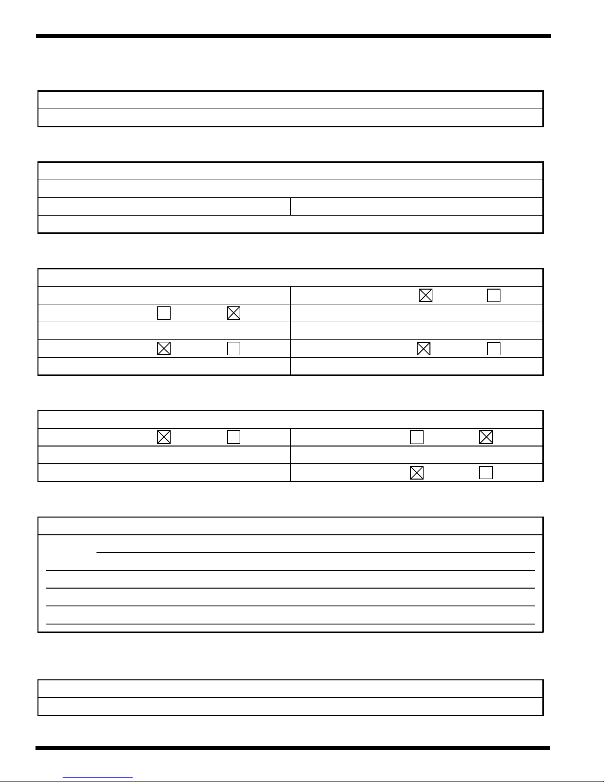
Applications
)
p
)
)
p
p
g
y
Orca III/ Orca III T Operation and Maintenance Manual
Chart - 7
PROCESS CONTROL CHART - 7
O rc a III/ Orca III T Lamina tor
MATERIALS MENU
Process: Thermal Encapsulation
Top m a t e ria l: 3 mil the r mal la min a te Botto m m a ter ial: 3 mil thermal laminate
O th er materia l(s): Prin ts
FRON T CO NTR OL P ANEL SETTING S
Speed ( ft/ m in ): 3 - 5 ( 90 - 152 cm/ min
Main ro lle r position: UP DOW N Main ro lle r s h im: 0 n i
Main ro lle r pressure: 80 psi
Top heater power: ON OFF B ottom h eater power: ON OFF
Top heater temperature: 220-225 oF ( 105-107 oC
Roller direction: FWD REV
Bottom h eater temperature: 220-225 oF (105-107 oC
REAR CONTROL PANEL SETTINGS
Pull rolle r c lu tc h: O N OFF Pu ll ro lle r position: UP D OWN
Pull rolle r c lu tc h pressure: 80 psi
Pull rolle r s h im: 0 n i
Pull rolle r pressure: 80 psi
Cooling fans: ON OFF
SPECIAL INSTRUCTIONS
Comments:
ee d will v a ry w ith th e opera t o rs c om fort ability to fe ed th e prin ts into the la mina tor. If th e o utput is
S
cu r lin
If u s ing ot h e r th a n a 3 mil th e r mal film, u s e the T e mperature chart from Section 6.1 .
, adjust the brake tension on the roll of film(s). Adjust pressures, speed and temperature as
necessar
Reference diagram: Diagram - 7
to o btain a qua lity output . C ooling fan s may help, if n o t, r u n w ith c ooling fans OFF.
Page 6 - 20 © GBC Films Group February 2001
RELATED DIAGRAM
Page 88
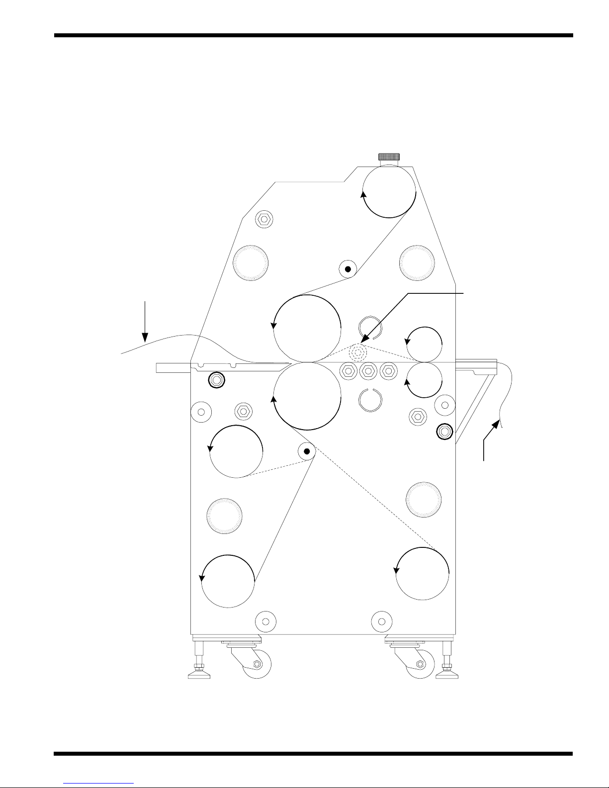
Diagram - 7
(
)
(
)
ApplicationsOrca III/ Orca III T Operation and Maintenance Manual
Thermal
Laminate
Print
Thermal
laminate
option
Thermal
lam ina te
Over the
idle r o p tio n
Hot
Hot
Finished
product
Thermal
lam ina te
option
© GBC Films Group February 2001
Page 6 - 21
Page 89

Applications
Orca III/ Orca III T Operation and Maintenance Manual
Chart - 8
PROCESS CONTROL CHART - 8
O rc a III/ O rc a III T L a min a tor
MATERIALS MENU
Pr o c e ss: Roll t o r o ll t h e r mal e nca p s ulation
To p materia l: 3 mil thermal lamina te Bo tt o m m a te rial: 3 mil thermal lamina te
O ther mat e ri a l(s ) : Roll o f print s o n a 3 inch c ore
FRONT CO NTRO L PANEL SETTINGS
Sp e e d ( ft/ min ): 3 - 5 ( 9 0 - 1 52 c m/ m in ) R o lle r d ir e c t io n: FWD R E V
Main roller pos it io n: U P D OW N Main roller shim: 0 nip
Main roller pres s ure: 8 0 ps i
Top heater power: ON OFF B ottom heater power: ON OFF
Top heater tem perature: 220-225 oF ( 105-107 oC ) B ottom heater temp erature: 220-225 oF (1 0 5 -10 7 oC)
REAR CONTROL PANEL SETTINGS
Pull rol le r c l u tch: O N O F F Pull rol le r pos it io n: U P D OW N
Pull roller clutch pressure: 80 psi
Pull rol le r s him : 0 n i p
Pull roller pressure: 80 psi
Cooling fans: ON OFF
SPECIAL INSTRUCTIONS
Comments:
Sp e e d will vary with th e o p e ra to rs c o mfort a b ility to fe e d th e p r int s in to the la mina to r. If th e o u tp ut is
curling , adjust the brake tension on the roll of film(s). Adjust pressures, speed and tem pe rature as
If using other than a 3 m il thermal film, use the Te m p erature chart from Section 6.1 .
ne c ess a ry to obtain a q uality o utput. C o oling fan s m a y h e lp, if n o t , run with c o oling fans OFF .
Reference diagram: Diagram - 8
Page 6 - 22 © GBC Films Group February 2001
RELATED DIAGRAM
Page 90

Diagram - 8
ApplicationsOrca III/ Orca III T Operation and Maintenance Manual
Thermal
lam ina te
Over the
idle r o p tio n
Infeed
slitting
( option )
Roll o f p rin ts
image in
(--- = im ag e o u t)
Thermal
laminate
Hot
Hot
Finished
product
Thermal
laminate
( option )
Output
slitting
( option )
© GBC Films Group February 2001
Page 6 - 23
Page 91

Applications
Orca III/ Orca III T Operation and Maintenance Manual
Chart - 9
PROCESS CONTROL CHART - 9
O rc a III/ O rc a III T L a min a tor
MATERIALS MENU
Process: PSA en cap sulation - Main rollers
To p materia l: P S A lamina te Bo tto m m ate ria l: PS A laminate
Oth e r m a terial(s): Prints
FRONT CO NTRO L PANEL SETTINGS
Sp e e d ( ft/ min ): 3 - 5 ( 9 0 - 1 52 c m/ m in ) R o lle r d ir e c t io n: FWD R E V
Main roller pos it io n: U P D OW N Main roller shim: 0 nip
Main roller pres s ure: 8 0 ps i
Top heater power: ON OFF B ottom heater power: ON OFF
Top heater tem perature: 120 oF ( 49 oC ) Bottom heater tempe rature: 120 oF ( 49 oC )
REAR CONTROL PANEL SETTINGS
Pull rol le r c l u tch: O N O F F Pull rol le r pos it io n: U P D OW N
Pull roller clutch pressure: 80 psi
Pull rol le r s him : 0 n i p
Pull roller pressure: 80 psi
Cooling fans: ON OFF
SPECIAL INSTRUCTIONS
Comments:
Sp e e d will vary with th e o p e ra to rs c o mfort a b ility to fe e d th e p r int s in to the la mina to r. If th e o u tp ut is
cu r lin g, ad just t h e brak e t e n s ion on the u ppe r and low e r r o ll o f film b u t watch the re le ase lin e r
Even though it is PSA film, h e a t will as sist the b o nding a nd flow o f a d hes iv e on t h e prin t.
separation point so that it rem a ins just above/ below the main roller. Adjust pressures as neces sary to
achieve quality output.
Reference diagram: Diagram - 9
Page 6 - 24 © GBC Films Group February 2001
RELATED DIAGRAM
Page 92
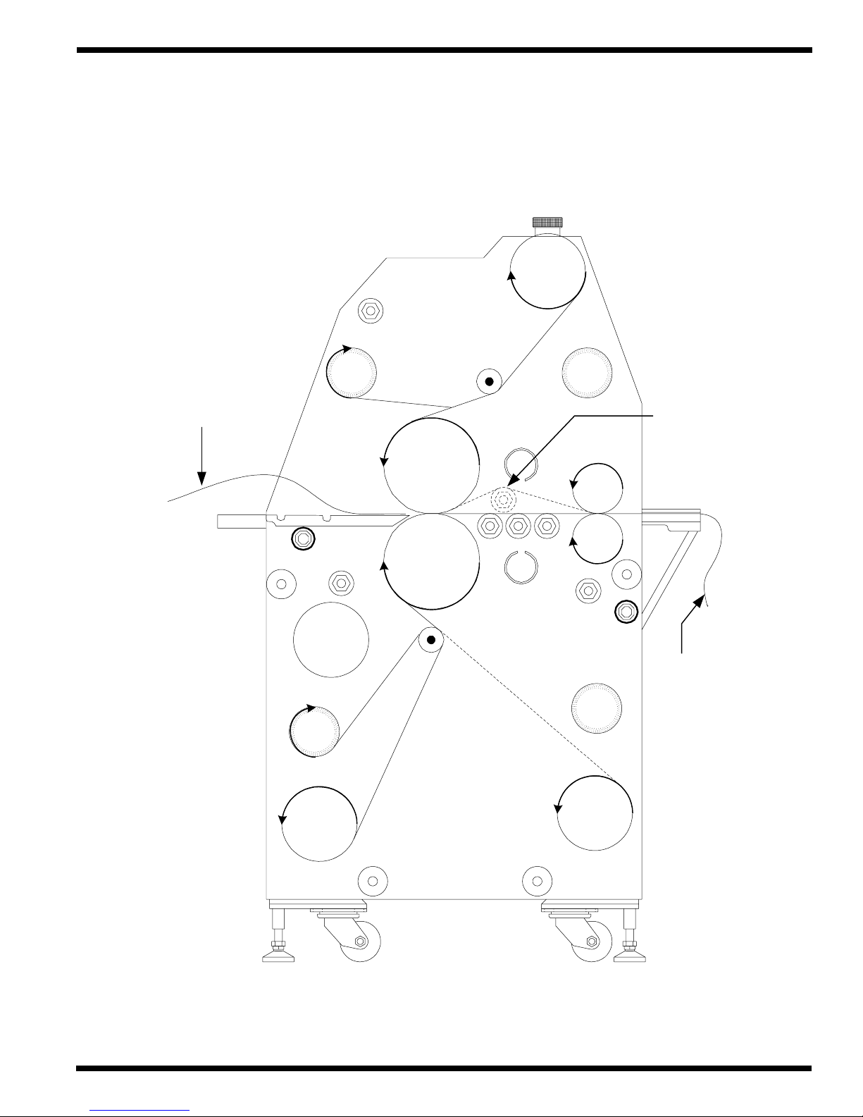
Diagram - 9
(
)
Liner
ApplicationsOrca III/ Orca III T Operation and Maintenance Manual
PSA
laminate
Print
Liner
PSA
lam ina te
Over the
idle r o p tio n
Warm
Warm
Finished
product
PSA
lam ina te
option
© GBC Films Group February 2001
Page 6 - 25
Page 93

Applications
Orca III/ Orca III T Operation and Maintenance Manual
Chart - 10
PROCESS CONTROL CHART - 10
O rc a III/ O rc a III T L a min a tor
MATERIALS MENU
Pr o c e ss: Roll t o r o ll PSA e n cap s ulatio n
To p materia l: P S A lamina te Bo tto m m ate ria l: PS A laminate
O ther mat e ri a l(s ) : Roll o f print s o n a 3 inch c ore
FRONT CO NTRO L PANEL SETTINGS
Sp e e d ( ft/ min ): 3 - 5 ( 9 0 - 1 52 c m/ m in ) R o lle r d ir e c t io n: FWD R E V
Main roller pos it io n: U P D OW N Main roller shim: 0 nip
Main roller pres s ure: 8 0 ps i
Top heater power: ON OFF B ottom heater power: ON OFF
Top heater tem perature: 120 oF ( 49 oC ) Bottom heater tempe rature: 120 oF ( 49 oC )
REAR CONTROL PANEL SETTINGS
Pull rol le r c l u tch: O N O F F Pull rol le r pos it io n: U P D OW N
Pull roller clutch pressure: 80 psi
Pull rol le r s him : 0 n i p
Pull roller pressure: 80 psi
Cooling fans: ON OFF
SPECIAL INSTRUCTIONS
Comments:
Sp e e d will vary with th e o p e ra to rs c o mfort a b ility to fe e d th e p r int s in to the la mina to r. If th e o u tp ut is
cu r lin g, ad just t h e brak e t e n s ion on the u ppe r and low e r r o ll o f film b u t watch the re le ase lin e r
Even though it is PSA film, h e a t will as sist the b o nding a nd flow o f a d hes iv e on t h e prin t.
separation point so that it rem a ins just above/ below the main roller. Adjust pressures as neces sary to
achieve quality output.
Reference diagram: Diagram - 10
Page 6 - 26 © GBC Films Group February 2001
RELATED DIAGRAM
Page 94
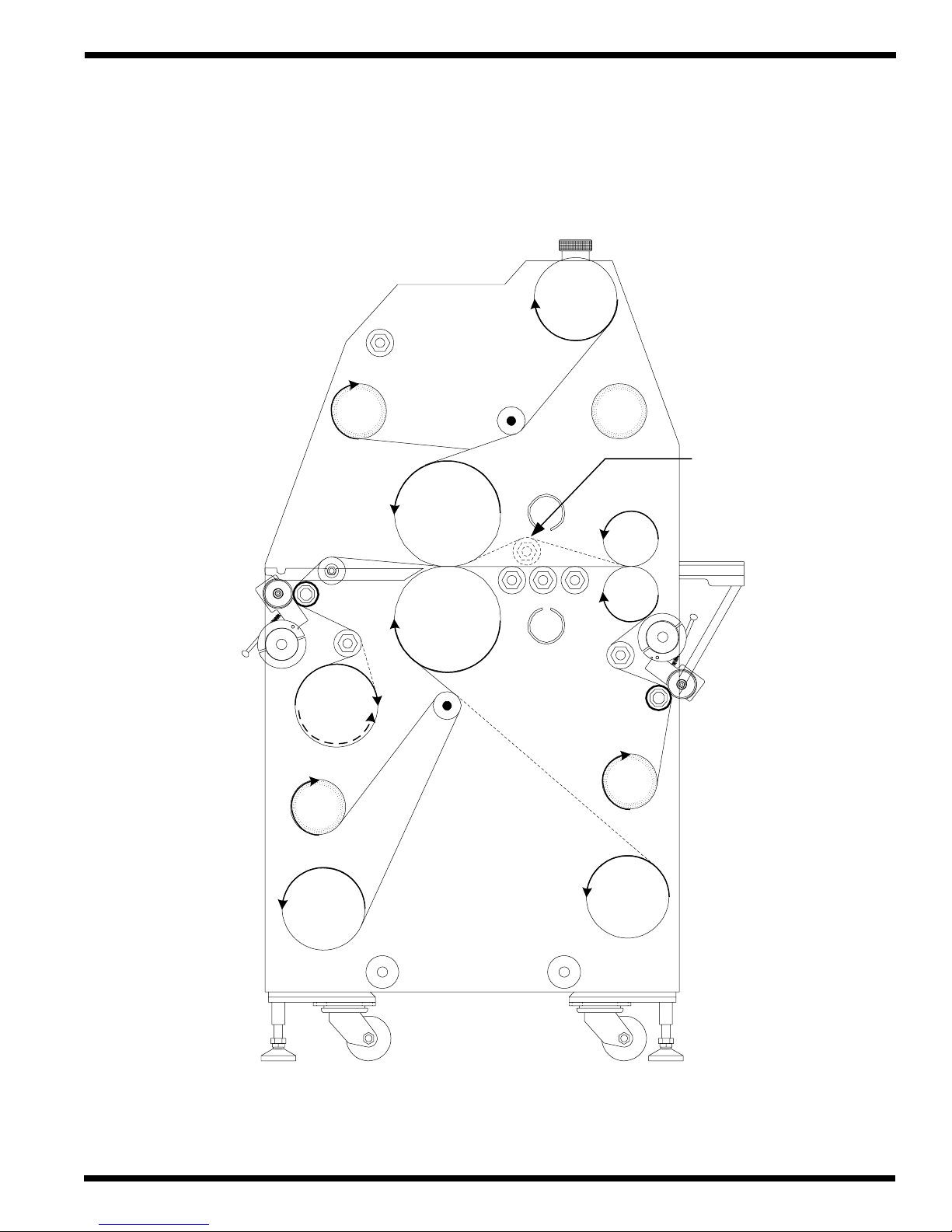
Liner
ApplicationsOrca III/ Orca III T Operation and Maintenance Manual
Diagram - 10
PSA
laminate
Over the
idle r o p tio n
Roll o f p rin ts
image in
( --- = im ag e o u t )
Liner
PSA
lam ina te
Warm
Warm
Finished
product
PSA
lam ina te
( option )
© GBC Films Group February 2001
Page 6 - 27
Page 95

Applications
Orca III/ Orca III T Operation and Maintenance Manual
Chart - 11
PROCESS CONTROL CHART - 11
O rc a III/ O rc a III T L a min a tor
MATERIALS MENU
Process: PSA en cap sulation - Pull rollers
To p materia l: P S A lamina te Bo tto m m ate ria l: PS A laminate
Oth e r m a terial(s): Prints
FRONT CO NTRO L PANEL SETTINGS
Sp e e d ( ft/ min ): 3 - 5 ( 9 0 - 1 52 c m/ m in ) R o lle r d ir e c t io n: FWD R E V
Main roller pos it io n: U P D OW N Main roller shim: N /A
Main roller pres s ure: N/A
Top heater power: ON OFF B ottom heater power: ON OFF
Top heater tem perature: 32 oF ( 0 oC ) Bottom heater tempe rature: 32 oF ( 0 oC )
REAR CONTROL PANEL SETTINGS
Pull rol le r c l u tch: O N O F F Pull rol le r pos it io n: U P D OW N
Pull roller clutch pressure: 80 psi
Pull rol le r s him : 0 n i p
Pull roller pressure: 80 psi
Cooling fans: ON OFF
SPECIAL INSTRUCTIONS
Comments:
Sp e e d will vary with th e o p e ra to rs c o mfort a b ility to fe e d th e p r int s in to the la mina to r. If th e o u tp ut is
cu r lin g, ad just t h e brak e t e n s ion on the roll of upp e r o r low e r r o ll o f film b u t watc h th e re leas e lin er
Use this process if the m ain rollers are too hot ( above 150 oF or 66 oC ) to use.
se p aration poin t s o th at it re main s jus t a b ove o r b e low t h e ma in r o ller. Ad just p r e s s ures a s nec e s s a r y
to achieve quality output.
Reference diagram: Diagram - 11
Page 6 - 28 © GBC Films Group February 2001
RELATED DIAGRAM
Page 96

Diagram - 11
ApplicationsOrca III/ Orca III T Operation and Maintenance Manual
PSA
lam ina te
Liner
Finished
product
PSA
lam ina te
( option )
Hot
Hot
Liner
PSA
lam ina te
© GBC Films Group February 2001
Page 6 - 29
Page 97

Applications
)
)
)
)
Orca III/ Orca III T Operation and Maintenance Manual
Chart - 12
PROCESS CONTROL CHART - 12
O rc a III / O rca III T La minator
MATERIALS MENU
Process: Vinyl trans fer with trim ming
To p m a te rial: N /A Bo tt o m m a te rial: V in y l
Other m aterial(s): Roll of electrostatic dry transfer images
FRONT CO NTRO L PANEL SETTINGS
Sp e e d ( ft/ min ): R o lle r d ir e c t io n: FWD R E V
Main roller pos it io n: U P D OW N Main roller shim: 0 nip
Orca III : 1 - 3 ft/ min. ( 30 - 91 cm/ m in.
Orca III T : 4 - 6 ft/ min. ( 122 - 183 cm / min.
Main roller pres s ure: 8 0 ps i
Top heater power: ON OFF B ottom heater power: ON OFF
Top heater temperature: Bottom heater tempe rature: 32 oF ( 0 oC )
Orca III : 290 oF ( 143 oC
Orca III T : 270 oF ( 132 oC
REAR CONTROL PANEL SETTINGS
Pull rol le r c l u tch: O N O F F Pull rol le r pos it io n: U P D OW N
Pull roller clutch pressure: 40 - 60 psi
Pull rol le r s him : 0 n i p
Pull roller pressure: 80 psi
Cooling fans: ON OFF
SPECIAL INSTRUCTIONS
Comments:
upper main rollers. Pull roller clutch pressure may vary depending on type of vinyl used. Do not use
ex c e s sive c lutch pres s ure. Too m u c h clu tch p r e s s ure will s tr e tc h the viny l a nd d istor t t h e tr a n sferr e d
im a ge a n d siz e . A lwa ys run co o ling f a n s . T he c o oling f a n s as s is t with the tra nsfe r p r o c e ss b y s h ock
Spee d s a nd t e mp e ra t u r e v a r y betwe e n t h e Orc a III a nd Orca III T du e to the d if fe r e n t ty pe o f
cooling the toners for better bonding with the vinyl and easier separation of the paper from the vinyl.
Reference diagram: Diagram - 12
Page 6 - 30 © GBC Films Group February 2001
RELATED DIAGRAM
Page 98

Diagram - 12
ApplicationsOrca III/ Orca III T Operation and Maintenance Manual
Ro ll o f
transfer
images
Trim
take-up
Hot
Cold
Paper
take-up
Finished
product
© GBC Films Group February 2001
Vinyl
Vinyl
( option )
Page 6 - 31
Page 99

Applications
)
)
)
)
Process: Vinyl trans fer no trimm ing
Orca III/ Orca III T Operation and Maintenance Manual
Chart - 13
PROCESS CONTROL CHART - 13
O rc a III / O rca III T La minator
MATERIALS MENU
To p m a te rial:
O th e r materia l(s ):
Ro ll o f electro s ta tic d r y tra n s fe r imag e s
Bo tt o m m a te rial: V in y l
FRONT CO NTRO L PANEL SETTINGS
Sp e e d ( ft/ min ): R o lle r d ir e c t io n: FWD R E V
Main roller pos it io n: U P D OW N Main roller shim: 0 nip
Main roller pres s ure: 8 0 ps i
Top heater power: ON OFF B ottom heater power: ON OFF
Top heater temperature: Bottom heater tempe rature: 32 oF ( 0 oC )
Orca III : 3 - 5 ft/ min. ( 91 - 152 cm/ m in.
Orca III T : 6 - 8 ft/ min. ( 183 - 244 cm / min.
Orca III : 290 oF ( 143 oC
Orca III T : 270 oF ( 132 oC
REAR CONTROL PANEL SETTINGS
Pull rol le r c l u tch: O N O F F Pull rol le r pos it io n: U P D OW N
Pull roller clutch pressure: 40 - 60 psi
Pull rol le r s him : 0 n i p
Pull roller pressure: 80 psi
Cooling fans: ON OFF
Comments:
upper main rollers. Pull roller clutch pressure may vary depending on type of vinyl used. Do not use
excessive clutch pressure. Too m uch clutch pressure will stretch the vinyl and distort the transferred
image an d s ize. Alw ays run coo ling fans. This process allows you to op erate at a little faster speed
because the toners are heated before it reaches the nip m inimizing the dw ell tim e n ecessa ry to transfer.
Reference diagram: Diagram - 13
Spee d s a nd t e mp e ra t u r e v a r y betwe e n t h e Orc a III a nd Orca III T du e to the d if fe r e n t ty pe o f
Page 6 - 32 © GBC Films Group February 2001
SPECIAL INSTRUCTIONS
RELATED DIAGRAM
Page 100

Diagram - 13
Ro ll o f
transfer
images
ApplicationsOrca III/ Orca III T Operation and Maintenance Manual
Paper
take-up
Vinyl
Hot
Cold
Finished
product
Vinyl
( option )
© GBC Films Group February 2001
Page 6 - 33
 Loading...