

Page 1

XHD3000 30-inch Widescreen LCD Monitor
USERGUIDE
®
Page 2

Page 3

Contents
Chapter 1: Checking Out Your Monitor . . . . . . 1
Package contents . . . . . . . . . . . . . . . . . . . . . . . . . . . . . . . . . . . . . . .2
Monitor features . . . . . . . . . . . . . . . . . . . . . . . . . . . . . . . . . . . . . . .3
Front . . . . . . . . . . . . . . . . . . . . . . . . . . . . . . . . . . . . . . . . . . . . . . .3
Back . . . . . . . . . . . . . . . . . . . . . . . . . . . . . . . . . . . . . . . . . . . . . . . 4
Monitor connections . . . . . . . . . . . . . . . . . . . . . . . . . . . . . . . . .5
Remote control features . . . . . . . . . . . . . . . . . . . . . . . . . . . . . . . . .7
Chapter 2: Setting Up Your Monitor. . . . . . . . 11
Connecting the monitor . . . . . . . . . . . . . . . . . . . . . . . . . . . . . . . .12
Connecting video inputs . . . . . . . . . . . . . . . . . . . . . . . . . . . .12
Connecting audio inputs and outputs . . . . . . . . . . . . . . . .14
Connecting power . . . . . . . . . . . . . . . . . . . . . . . . . . . . . . . . . .17
Setting up the optional speaker bar . . . . . . . . . . . . . . . . . .19
Connecting the USB hub . . . . . . . . . . . . . . . . . . . . . . . . . . . .20
Connecting a security cable . . . . . . . . . . . . . . . . . . . . . . . . .22
Preparing the remote control . . . . . . . . . . . . . . . . . . . . . . . .22
Positioning the monitor . . . . . . . . . . . . . . . . . . . . . . . . . . . . . . . .25
Ergonomic guidelines . . . . . . . . . . . . . . . . . . . . . . . . . . . . . . .26
Chapter 3: Using Your Monitor. . . . . . . . . . . . 27
Starting the monitor . . . . . . . . . . . . . . . . . . . . . . . . . . . . . . . . . . .28
Turning on the monitor . . . . . . . . . . . . . . . . . . . . . . . . . . . . .28
Using the EzTouch menu . . . . . . . . . . . . . . . . . . . . . . . . . . . . . . .29
Using the shortcut menu . . . . . . . . . . . . . . . . . . . . . . . . . . . .30
Using the main menu . . . . . . . . . . . . . . . . . . . . . . . . . . . . . . .32
Adjusting monitor settings . . . . . . . . . . . . . . . . . . . . . . . . . . . . .33
Using monitor menus . . . . . . . . . . . . . . . . . . . . . . . . . . . . . . .34
Changing Windows screen settings . . . . . . . . . . . . . . . . . .38
Using the speaker bar . . . . . . . . . . . . . . . . . . . . . . . . . . . . . . . . . .40
Power management . . . . . . . . . . . . . . . . . . . . . . . . . . . . . . . . . . .41
Energy declaration . . . . . . . . . . . . . . . . . . . . . . . . . . . . . . . . .41
Maintaining . . . . . . . . . . . . . . . . . . . . . . . . . . . . . . . . . . . . . . . . . . .42
i
Page 4

Contents
Chapter 4: Troubleshooting . . . . . . . . . . . . . . . 43
Troubleshooting guidelines . . . . . . . . . . . . . . . . . . . . . . . . . . . . 44
Troubleshooting symptoms . . . . . . . . . . . . . . . . . . . . . . . . . . . . 44
No power . . . . . . . . . . . . . . . . . . . . . . . . . . . . . . . . . . . . . . . . . 44
No picture . . . . . . . . . . . . . . . . . . . . . . . . . . . . . . . . . . . . . . . . 44
Display colors are wrong . . . . . . . . . . . . . . . . . . . . . . . . . . . 46
Picture has shadows or “ghosts” . . . . . . . . . . . . . . . . . . . . 46
Color is not uniform . . . . . . . . . . . . . . . . . . . . . . . . . . . . . . . 46
Image is not sized or centered correctly . . . . . . . . . . . . . 47
Bad picture . . . . . . . . . . . . . . . . . . . . . . . . . . . . . . . . . . . . . . . 47
Gaming support . . . . . . . . . . . . . . . . . . . . . . . . . . . . . . . . . . . 48
The monitor has pixels that are always dark or too bright 49
Speaker bar does not work . . . . . . . . . . . . . . . . . . . . . . . . . 49
HDCP FAQs . . . . . . . . . . . . . . . . . . . . . . . . . . . . . . . . . . . . . . . . . . . 50
Video FAQs . . . . . . . . . . . . . . . . . . . . . . . . . . . . . . . . . . . . . . . . . . . 52
Chapter 5: Using the Universa l Remote Control53
Programming the universal remote control . . . . . . . . . . . . . . 54
Resetting the remote control . . . . . . . . . . . . . . . . . . . . . . . 55
Recording with the remote control . . . . . . . . . . . . . . . . . . 55
Detecting low batteries . . . . . . . . . . . . . . . . . . . . . . . . . . . . 55
Using the IR Blaster . . . . . . . . . . . . . . . . . . . . . . . . . . . . . . . . . . . 56
Remote control programming codes . . . . . . . . . . . . . . . . . . . . 57
Default device ID codes . . . . . . . . . . . . . . . . . . . . . . . . . . . . 57
Television codes . . . . . . . . . . . . . . . . . . . . . . . . . . . . . . . . . . . 57
DVD player codes . . . . . . . . . . . . . . . . . . . . . . . . . . . . . . . . . . 60
VCR codes . . . . . . . . . . . . . . . . . . . . . . . . . . . . . . . . . . . . . . . . 62
PVR codes . . . . . . . . . . . . . . . . . . . . . . . . . . . . . . . . . . . . . . . . 64
Video accessory codes . . . . . . . . . . . . . . . . . . . . . . . . . . . . . 65
Audio amplifier codes . . . . . . . . . . . . . . . . . . . . . . . . . . . . . . 66
Audio receiver codes . . . . . . . . . . . . . . . . . . . . . . . . . . . . . . . 66
Audio accessory codes . . . . . . . . . . . . . . . . . . . . . . . . . . . . . 67
Cable set-top box codes . . . . . . . . . . . . . . . . . . . . . . . . . . . . 68
Satellite set-top box codes . . . . . . . . . . . . . . . . . . . . . . . . . 68
Media Center controller codes . . . . . . . . . . . . . . . . . . . . . . 69
ii
Page 5

www.gateway.com
Appendix A: Specifications . . . . . . . . . . . . . . . 71
Monitor specifications . . . . . . . . . . . . . . . . . . . . . . . . . . . . . . . . . .72
Video modes . . . . . . . . . . . . . . . . . . . . . . . . . . . . . . . . . . . . . . .74
Speaker bar specifications . . . . . . . . . . . . . . . . . . . . . . . . . . . . . .76
Remote control specifications . . . . . . . . . . . . . . . . . . . . . . . . . . .77
Appendix B: Safety , Regulatory, and Lega l
Information. . . . . . . . . . . . . . . . . . . . . . . . . . . . 79
Recycling . . . . . . . . . . . . . . . . . . . . . . . . . . . . . . . . . . . . . . . . . .81
iii
Page 6

Contents
iv
Page 7

CHAPTER1
Checking Out Y our Monitor
• Package contents
• Monitor f eatures
• Remot e control f eature s
1
Page 8
CHAPTER 1: Checking Out Your Monitor
Pa ckage cont ents
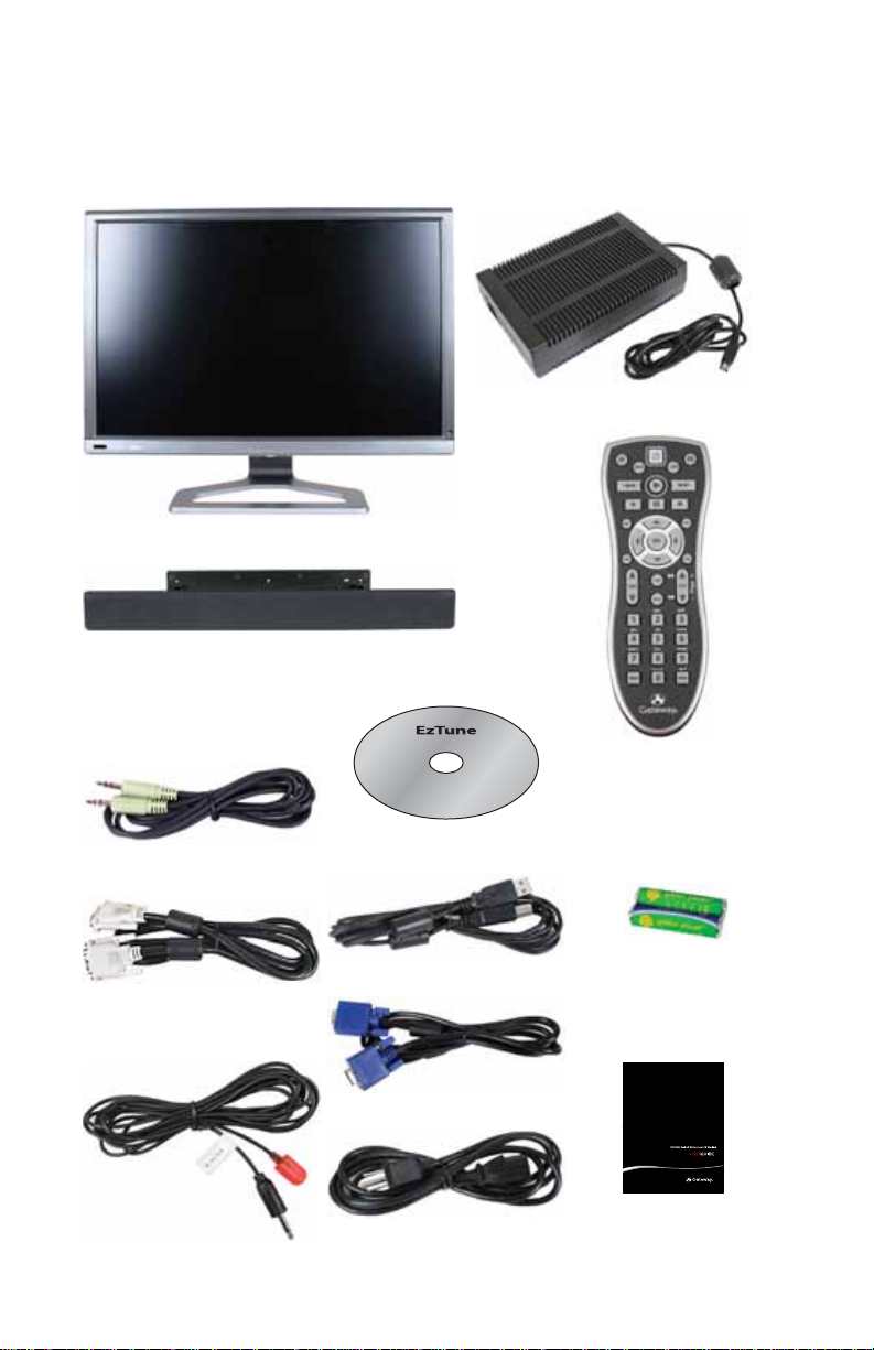
Your monitor’s box should contain the following items:
Monitor (base attached)
Speaker bar
(optional on some models))
ACpower adapter
Audio patch cable
DVI vi de o c ab le
IR blaster cable
2
EzTune software CD
USB hub cable
VGA video cable
AC p ow er co rd
Univers al rem ote con tro l
Two AA batteries
(for remote control)
User Guide
Page 9
www.gateway.com
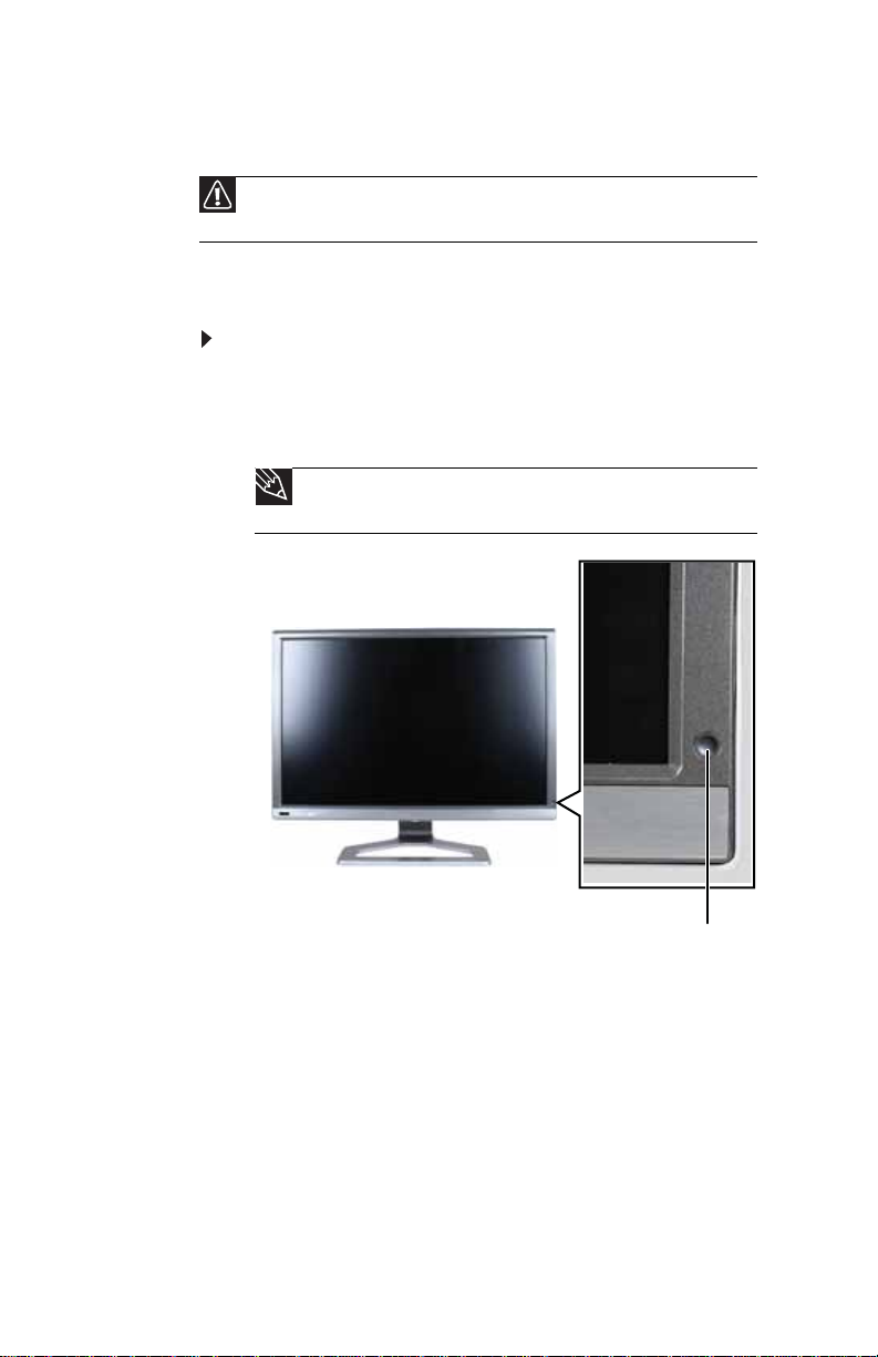
Monitor f eature s
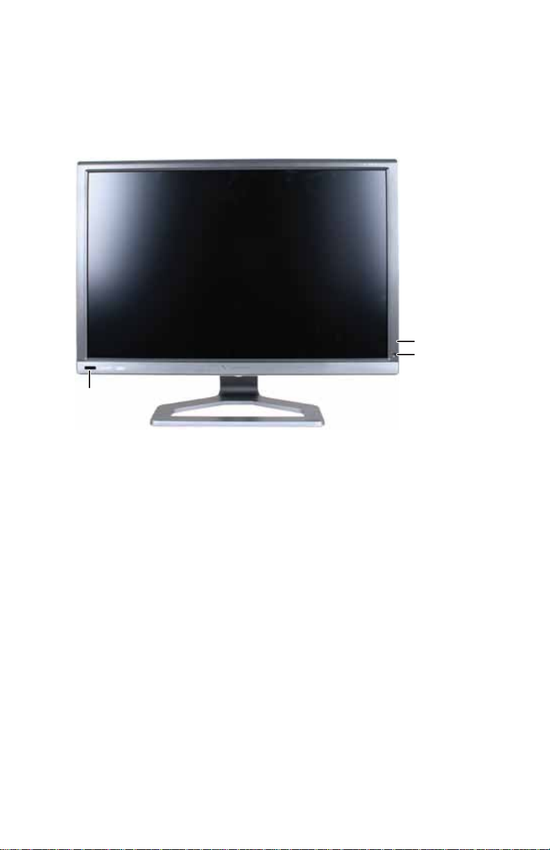
Front
IR remote sensor
Menu touch button*
Power touch
button*/Power LED
* For instructions on using the
touch but t ons, see
EzTouch menu” on
page 29
“Using the
.
3
Page 10
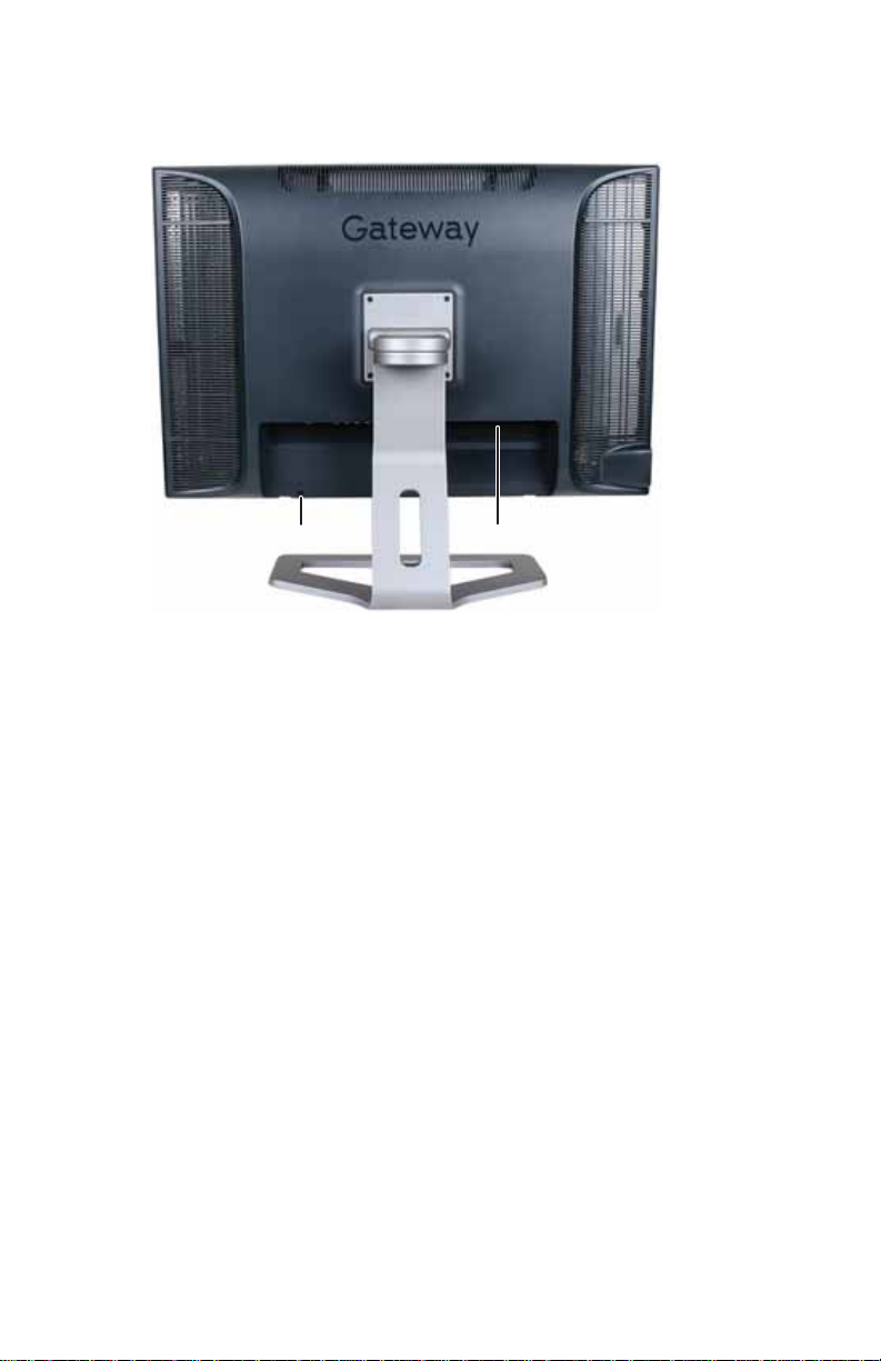
Back
CHAPTER 1: Checking Out Your Monitor
Cable lock slot
Ports and jacks (underneath)
4
Page 11
www.gateway.com
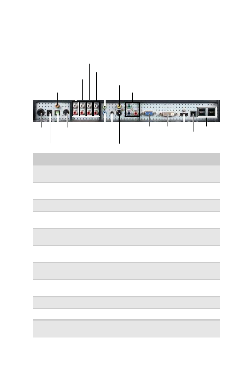
Monitor connec tions
Alth ou gh th is g ui de cov er s b as ic set up, re fer to t he foll owi n g
illustration for advanced audio and video setup help.
L/R audio in (composite)
L/R audio in (component)
L/R audio in (S-Video)
L/R audio out
S/PDIF coaxial output
DVI mode audio
Composite video
Component video
Monitor
power
S/PDIF TOSLINK output
Speaker bar power
Speaker bar audio
VGA mode audio
IR blaster
S-Video
VGA DVI HDMI
(connect to
USB-B
computer)
USB-A
(connect to
USB
devices)
Connector Use
S/PDIF coaxial output Connect to the S/PDIF (digital) coaxial in jacks on a
L/R audio out Connect t o the au dio in jacks on a stan dard tw o-channel
L/R audio in (S-Video) Connect to the L/R audio out jacks on the S-Video device.
L/R audio in
(composite video)
L/R audio in
(component video)
DVI mode audio Connect to the headphone/speakers jack on your
Comp os ite vid e o Connect t o the comp osite v ideo out jac ks on a composit e
Component video Connect to the component video out jacks on a
Monitor power Conn ec t to th e m on ito r ’s AC p ow er ad ap ter.
device to play the audio on that device.
stereo device to play the audio on that device.
Connect to the L/R audio out jacks on the composite
video device.
Connect to the L/R audio out jacks on the component
video device.
computer for the DVI display mode’s audio source.
video sourc e, such as a VCR.
component video sour ce , such as ahigh-end DVD player.
Speaker bar power Connect to the optional speaker bar.
S/PDIF TOSLINK
output
Connect to the S/PDIF TOSLINK (digital optical) audio in
jacks on a device to play the audio on that device.
5
Page 12

CHAPTER 1: Checking Out Your Monitor
Connector Use
Speaker bar audio Connect to the optional speaker bar.
VGA mo de au di o Connect to the headphone/speakers jack on your
IR b las ter Conn ec t to the I R bl as ter se ns or.
S-Video Connect to the S-Video out jack on an S-Video video
VGA Conn ec t to a VGA ja ck on a VGA vi de o so ur ce, suc h as
DVI Connect t o a D VI jack on a D VI v ideo sour ce , suc h as y our
HDMI Connect to an HDMI jack on an HDMI video source, such
USB-B Connect to a standard USB port (USB-A) on your
USB-A Connect to USB devices, such as cameras, printers, and
computer for the VGA display mode’s audio source.
source, such as a DVD player.
your computer.
computer.
as a set-top box.
computer. This lets your monitor act as a USB hub.
flash drives.
6
Page 13
www.gateway.com
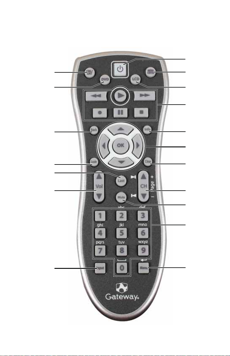
R emote co ntrol f eatur es
Select
cable/satellite
remote mode
Power
Open Window s
Media Center
Select DVD
remote mode
Back menu
Programming
guide/DVD
menu
Channel recall
Volume
Select LCD
remo te mo de
Playback
controls
Display
on-screen
information
Menu controls
Clear/exit/
cancel
(depends on
mode)
Channel/skip
chapter
(depends on
mode)
Mute
Numeric
keypad
Input (video
source select)
Menu
7
Page 14

CHAPTER 1: Checking Out Your Monitor
Important
Your remote control works for your monitor, but you must program it to
work for your other devices (such as cable or satellite set-top boxes and DVD
players). For more information, see “Progra mmi n g t he universal remot e con trol”
on page 54.
Button Function
Select cable/satellite
remote mod e
Select DVD remote
mode
Back menu Press t o go bac k on e menu le vel (while in an on-sc r een
Programming
guide/DVD menu
Channel recall Press to return to the previous channel that was
Volume Press to adjust the volume.
Input (video source
select)
Power Press to turn the monitor on and off. If using a di s play
Open Windows Media
Center
Select LCD remote
mode
For univ ersal r emot e contr ol func tions, pre ss t o cont rol
your cable or satellite set-top box.
For univ ersal r emot e contr ol func tions, pre ss t o cont rol
your DVD player.
menu).
Press to open your cable or satellite provider’s
programming guide (while in cable or satellite mode)
or to open the DVD menu (while in DVD mode).
viewed.
Press LCD, then press Input to select the video source.
You can select DVI, HDMI, VGA, Composite,
Component, or S-Video.
mode other than LCD, press to turn off the selected
component.
While in LCD mode, press to open Windows Media
Center. (Your computer must have a Windows Media
Center IR receiver installed. IR receivers must be
purchased separately.)
After usin g uni v ers al r emot e contr ol func tio ns (suc h a s
for a set- top box or DVD pl aye r) , pr ess thi s b ut ton to
control your LC D monitor.
Playback controls Press to operate t he pla y bac k functions of the selec ted
Display on-screen
information
Menu controls Press to navigate through on- screen menus.
Clear/exit/cancel Press to clear a character, exit a menu, or cancel a
device.
Press to display the current resolution and video input
mode.
command. (Function depends on the current mode.)
8
Page 15

www.gateway.com
Button Function
Channel/skip
chapter/tune (depends
on mode)
Mute Press to mute the soun d, an d press agai n to res tore
Numeric keypad Press to directly enter channel numbers, chapter
Menu Press to open the LCD panel’s on-screen menu.
Press to change the channel or skip chapters. (Function
depends o n the current m ode.)
sound.
numbers, or values in menu sett ings.
Important: You may notice a delay when the Menu
button is first pressed. The first time the Menu button
is pressed, the on-screen menu changes from 2’ mode
(smaller sized menu that is controlled from the touch
pad) to 10’ mode (larger sized menu that is controlled
from the re mote con t rol ). If you press a button on the
front panel after pressing the Menu button on the
remote, you will experience another delay while the
on-screen menu changes from 10’ mode to 2’ mode.
9
Page 16

CHAPTER 1: Checking Out Your Monitor
10
Page 17

CHAPTER2
Setting Up Y our Monit or
• Connec ting the monitor
• Setting up the optional speak er bar
• Positioning the monitor
11
Page 18
CHAPTER2: Setting Up Your Monitor
Connec ting the monit or
Connec ting video inputs
Important
To use the monitor’s full (highest) resolution (2560× 1600), you must use
the included dual-link DVI cable to connect the monitor to a dual-link capable
video card on your computer.
A single-link DVI cable or video card limits resolution to 1920× 1200.
VGA and HDMI connections are also limited to a maximum 1920 × 1200
resolution.
Tip
Because of your monitor’s built-in video processing features, we
recommend that if you use a DVD player that is not high-definition, you should
disable your player’s built-in up conversion and output video at 480i when
possible.
To connect your computer and ot her video sourc es to
your m oni tor:
1 Position your computer and the monitor so you can
reach the ba ck o f e ach .
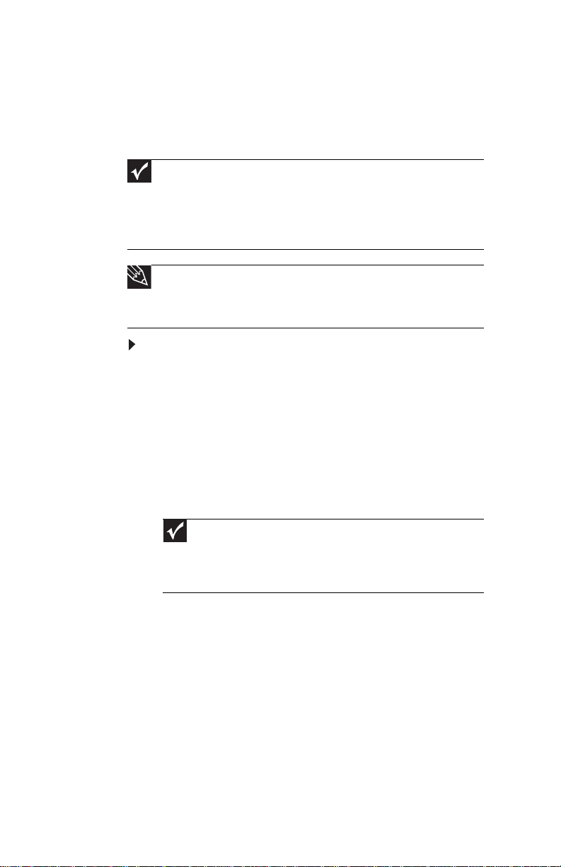
2 Make sure that your computer is turned off, then connect
the DVI video cable to the D VI v ideo port (white) on your
computer.
-ORIf your computer has only an analog VGA (blue) port,
connect the VGA video cable to the port.
12
Important
Yo u should not co nnec t t o bot h t he D VI and V GA po rts on t he same
computer at the same time. However, you may connect up to three
computers to the display at the same time using the DVI, VGA, and HDMI
ports and switch between the inputs using the EzTouch controls or
remo te c o nt ro l.
Page 19
www.gateway.com
3 Connect the other end of the video cable to t he matching
video port on the back of your monitor.
OR
4 Connect other video source s (such as a D VD play er , vi deo
camera, or video recei ver) t o the appropriat e video jack s
on the back of the monitor.
• For basic video quality, connect your video device’s
COMPOSITE jack to the corresponding jack on the
back of your monitor (cable not included).
• For better video quality, connect your video device’s
S-VIDEO jack to the corresponding jack on the back
of your monitor. (cable not i ncluded)
• For best video quality, connect your video device’s
COMPONENT VIDEO jacks (green Y, bluePb, and
red Pr) or HDMI jacks to the correspon d ing jacks on
the back of your monitor (cables not included).
13
Page 20
CHAPTER2: Setting Up Your Monitor
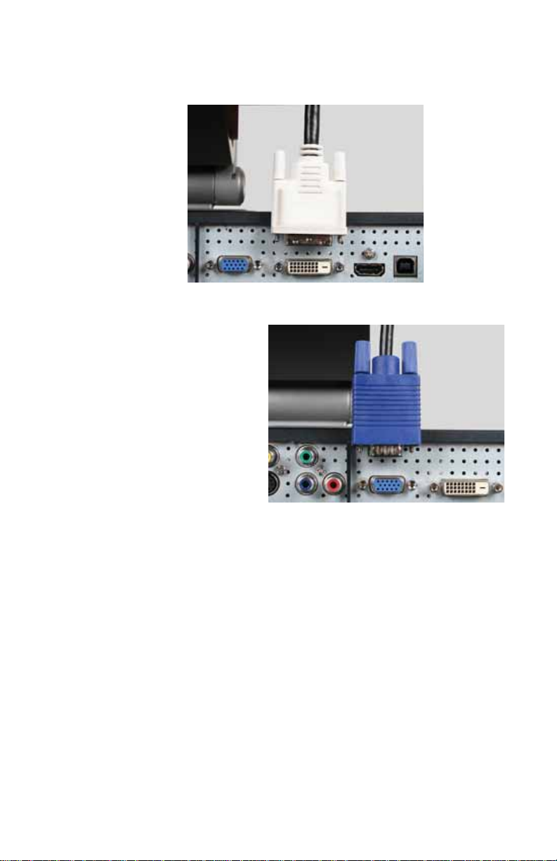
Important
When displaying standard-definition video (480i or 480p), you
should set your video source device’s output to 480i. Your monitor has
superior deinte rlacing and v ideo proce ssing f eatures t hat are best utiliz ed
on 480i video.
When displaying high-definition video (720p, 1080i, and 1080p), you
should set your video source device’s output to 1080i fo r b e st
performance.
Composite video
Component video
VGA
S-Video
5 Connect the audio inputs that correspond to the video
inputs. For more informatio n, see “Connecting audio
inputs and outputs” on page 14.
Connec ting audio inputs and outputs
To connect your computer and ot her audio sourc es to
your m oni tor:
1 Position your computer and the monitor so you can
reach the ba ck o f e ach .
DVI
HDMI
14
Page 21
www.gateway.com
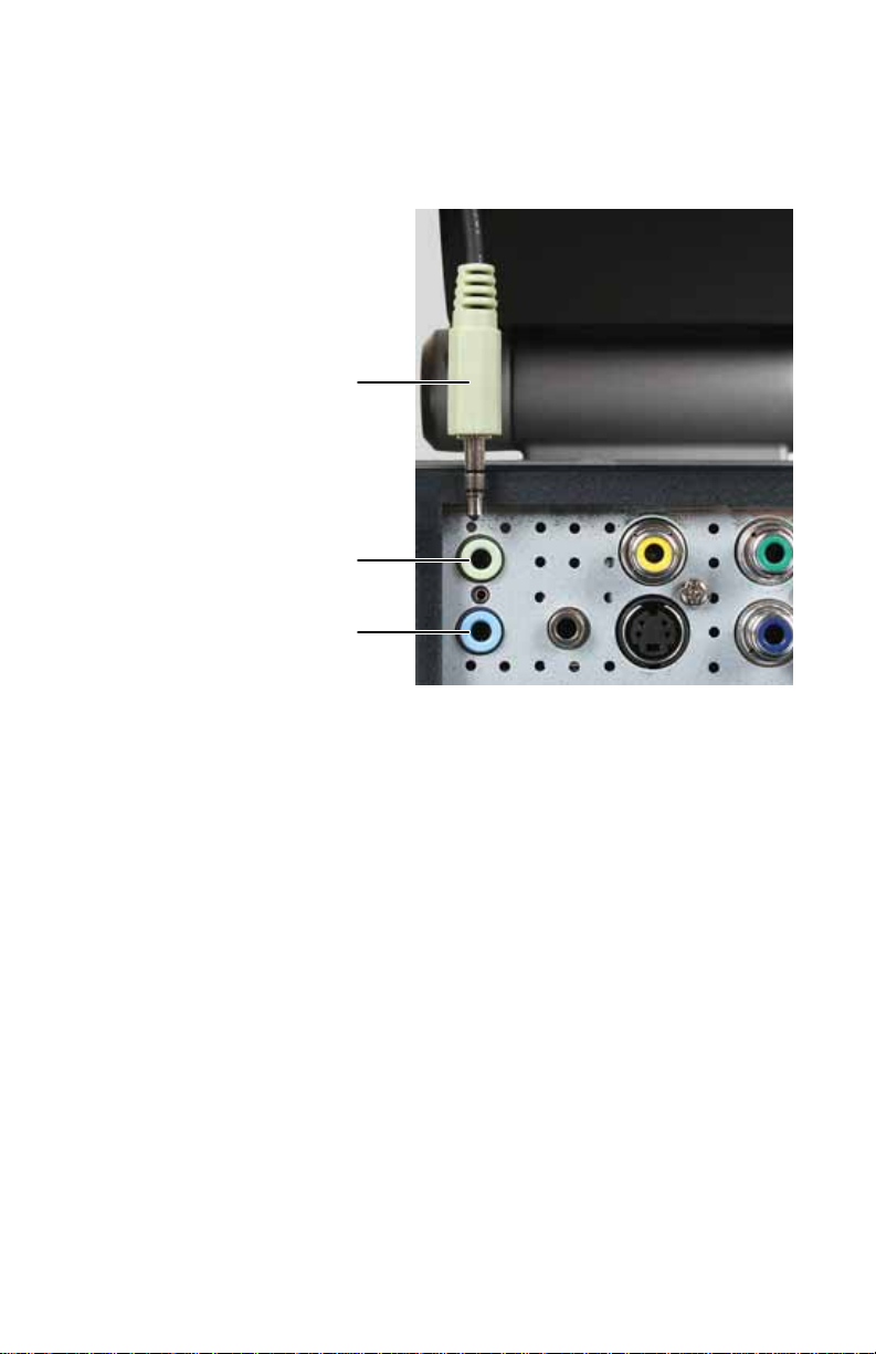
2 Connect the stereo patch cable to your computer’s
headphone jack (green) and your monitor’ s D V I audio or
VGA audio jack. This is the most basic audio connection
for your computer.
Stereo
patch
cable
DVI audio
jack
VGA a udi o
jack
15
Page 22
CHAPTER2: Setting Up Your Monitor
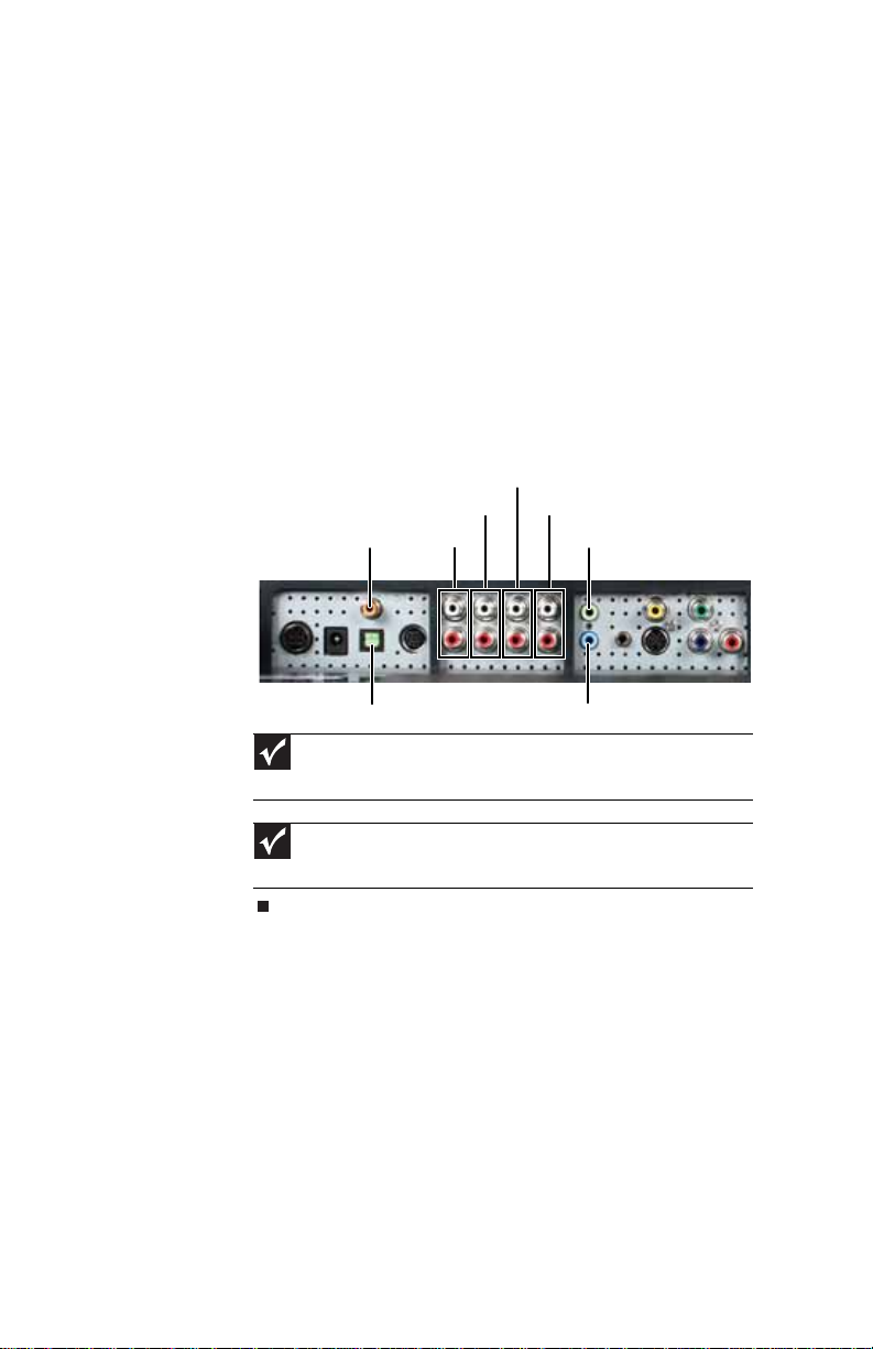
3 Connect other audio sources (such as a DVD player or
audio receiver) to the appropriate audio jacks on the
back of th e mo nito r.
• For basic audio quality, connect your audio source to
the L/R (two-channel stereo) audio in jacks for the
device. Your monitor has L/R stereo jack pairs that
are associated with S-Video, Composite (standard),
and Component video modes (cables not included).
• For best audio perfor mance, if your video connection
uses HDMI, the digital audio is also conveye d along
the same cable, and no additional audio connection
is required. You may need to set your video sour c e’s
audio mode to PCM or ANALOG to hear the audio.
See your source device’s user guide for more
information.
Composite audio in
S/PDIF OUT ( coax ial)
S-Video audio in
Audio out
Compo ne nt au di o in
DVI m od e a ud io
16
S/PDIF OUT (Toslink)
VGA mode audio
Important
The connector type used fo r S-Video, Composite, and Component
audio inputs is also known as an RCA connector.
Important
The connec to r type u sed f or D VI mode audio and VG A mode audio
inputs is also known as a 3.5mm stereo connector.
You can connect your monitor to another audio device, such
as an audio receiver, to project the sound.
Page 23
To connect your monitor to a receiver or other audio
device:
• For basic audio quality, connect your audio device to the
L/R (two-channel ster eo) audio out jac k s on t h e back of
the monitor.
-ORFor best audio performance, you can connect your a udio
device t o one of the S/PDIF output jack s. All analog audio
inputs routed into t he monit or a r e output on the S/ PDIF
output ports.
Connec ting pow er
To connect power:
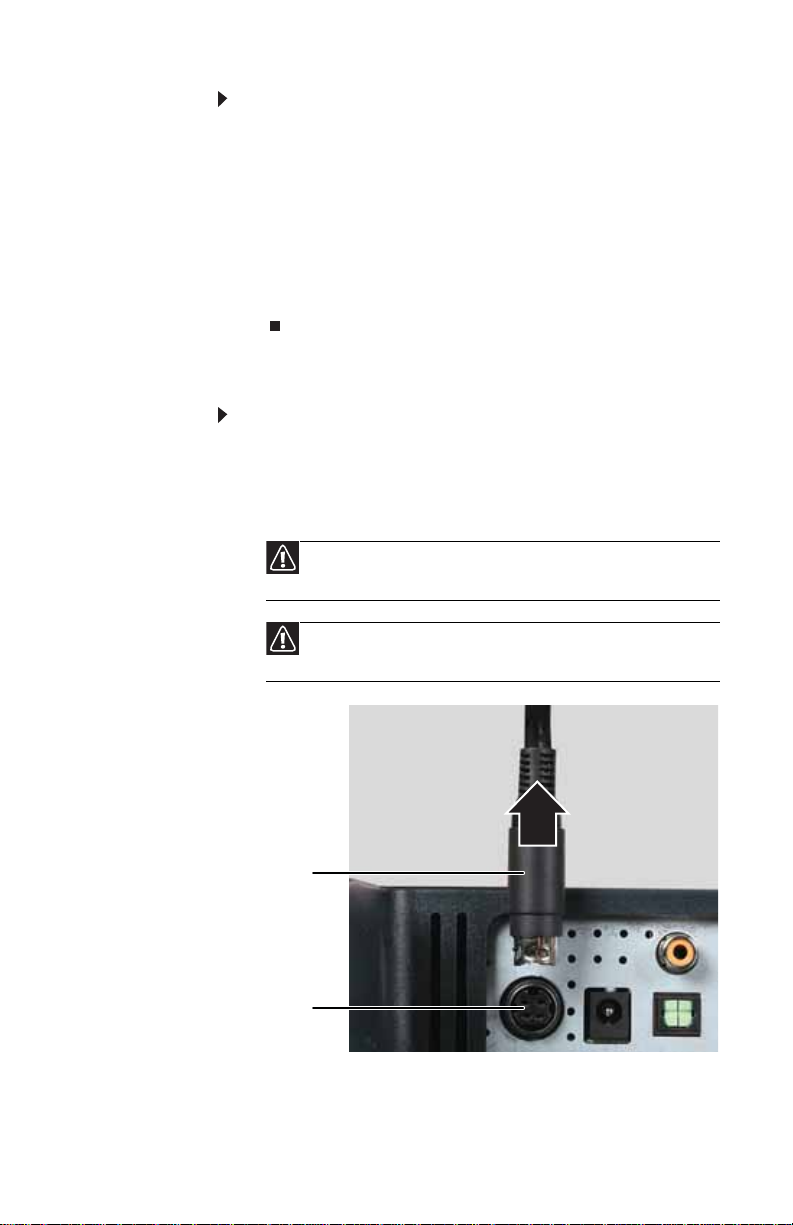
1 Position yo ur monitor so you can reach the back.
2 Plug the adapter’s power cord into the power connector
under the back of the monitor. The power cord is locked
into place.
Caution
Make su re th a t th e pi n s i n th e p o w er c ord l in e u p wi th th e h o l es
in the power connect or. Failure to do so ma y resu lt in bent or bro k en pins.
www.gateway.com
Caution
Plug the power adapte r into the monitor before you plug the
power adapter into a power outlet.
Power
adapter
locking
sleeve
Power
connector
17
Page 24
CHAPTER2: Setting Up Your Monitor
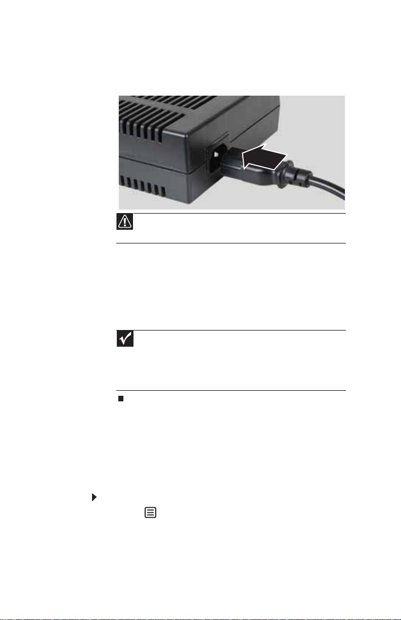
3 Plug the AC power cord into the AC power adapter, then
plug the ACpower cord into a power outlet. We
recommend using a surge protector to protect your
mon ito r fro m vo lt age s pi kes.
Caution
Do not block the ventilation openings in the power adapter. Make
sure to place the adapter in a well-ventilated area.
4 To make sure that the m onitor ’s power is c orrectly
con necte d, che ck the powe r to uch bu tton on the fron t
button panel. The pow er icon on the power but ton glows
blue when plugged in or amber when no source is
detected. The button glows purple when the monitor is
turned off. If the power ico n is n ot vis ibl e, power is n o t
connected.
18
Important
The first time ACpower is conne cted, the monitor initializes for
about 15seconds. While it is initializing, two of the buttons on the touch
panel flash alternately. The monitor is unresponsive when ACpower is
initially c onn ected. When the butt o ns stop flashing, the monit o r t urns on
and looks for any incoming video signals (see “Star ti n g th e m o n ito r” on
page 28).
Disabling the automatic product tour
The monitor is configured at the factory to automatically begin
playing a brief tour of the product and it’s features whenever
the monitor is turned on and no input signal is present. We
enco ur ag e yo u to wa tch t hi s to u r to l ea rn a b ou t the fea tu res
and capabilities of your monitor display.
To disable the product tour:
1 Touch (Menu).
Page 25
www.gateway.com
2 Touch (Main Menu), (Advanced),
(Integrat ed Product T our), t he n t ou c h (Disable).
The product tour is disabled.
After the tour is disabled, you can view it again at any
time by pressing and holding the power button for five
seconds.
For more information on using the touch buttons, see
“Using the EzTou ch menu” on page 29.
Setting up the optional speaker bar
An optional speaker bar , which has ex cellent sound, is available
for mounting underneath your monitor. You can order a
speaker bar from www.gateway.com
To install the speaker bar:
1 Tu rn of f t h e m o n i t o r.
Important
If you con ne ct th e s pe aker bar to th e m on ito r wh il e th e m on ito r
is turned on, the speaker bar will not initiali z e and will no t work corr ec tly.
If this happens, turn the monitor off, then back on to enable the speaker
bar.
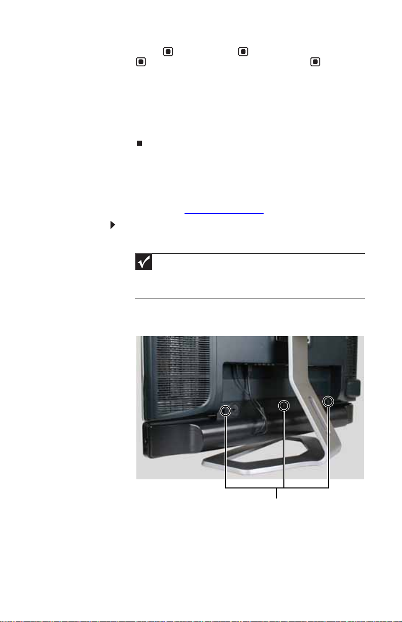
2 Remove the three thu mbscrews from the ba ck of the
monitor.
.
Thumbscrews
3 Sli de the spe ake r ba r o nto the bo ttom of th e mo ni tor,
then use th e thre e thu mbscr ews to se cure i t into pl ace.
19
Page 26
CHAPTER2: Setting Up Your Monitor
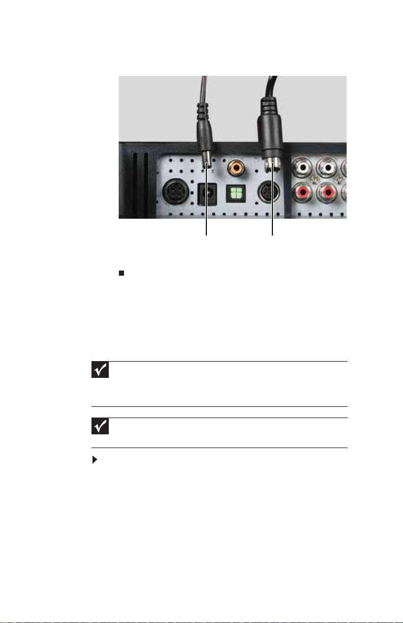
4 Plug the speaker bar’s power and audio plugs into the
appropriate connectors underneath the monitor.
Speaker bar power
For information on using the speaker bar, see “Using the
speaker bar” on page 40.
Connec ting the U SB hub
Y our monitor has a built- in, powered, USB 2. 0 6-port hub. When
connected to your computer’s USB port, the hub provides six
USB ports for co nnectin g as many as s ix USB-c ompat ible
devices.
Important
For the monitor’s U SB h ub to provide high-spee d U S B 2.0 connecti ons, the
hub must be connected to a USB2.0 port on your computer. If the hub is
connected to a USB 1.1 port, the monitor’s ports will provide only the slower
USB1.1 connections.
Important
This monitor requires a driver to work correctly. The driver is included on
the EzTune installationCD.
To connect the USB hub:
1 T urn on your computer, then install the EzT une s of tw ar e
from the included EzTune installationCD.
2 Position yo ur monitor so you can reach the back.
Speaker bar audio
20
Page 27
www.gateway.com
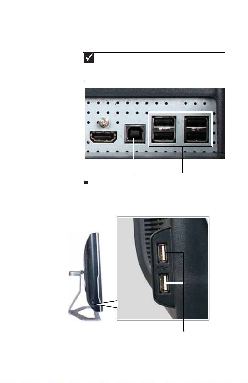
3 Connect the included USB cable t o the U SB-B port on t he
back of the monitor, then connect the other end of the
cable to a USB-A (standard) port on your computer.
Important
Only the computer and monitor should be connected during the
first installa tion and bootup. Do not p lug an y de v ices in t o t he U SB-A ports
at this time. After the USB driver is installed, it is safe to plug additional
devices into the monitor’s USB hub.
USB-B port (connect to computer) USB-A hub ports
Additional USB jacks
Additional USB jacks are locat ed on th e left side of t he monit or.
USB -A p ort s
21
Page 28
CHAPTER2: Setting Up Your Monitor
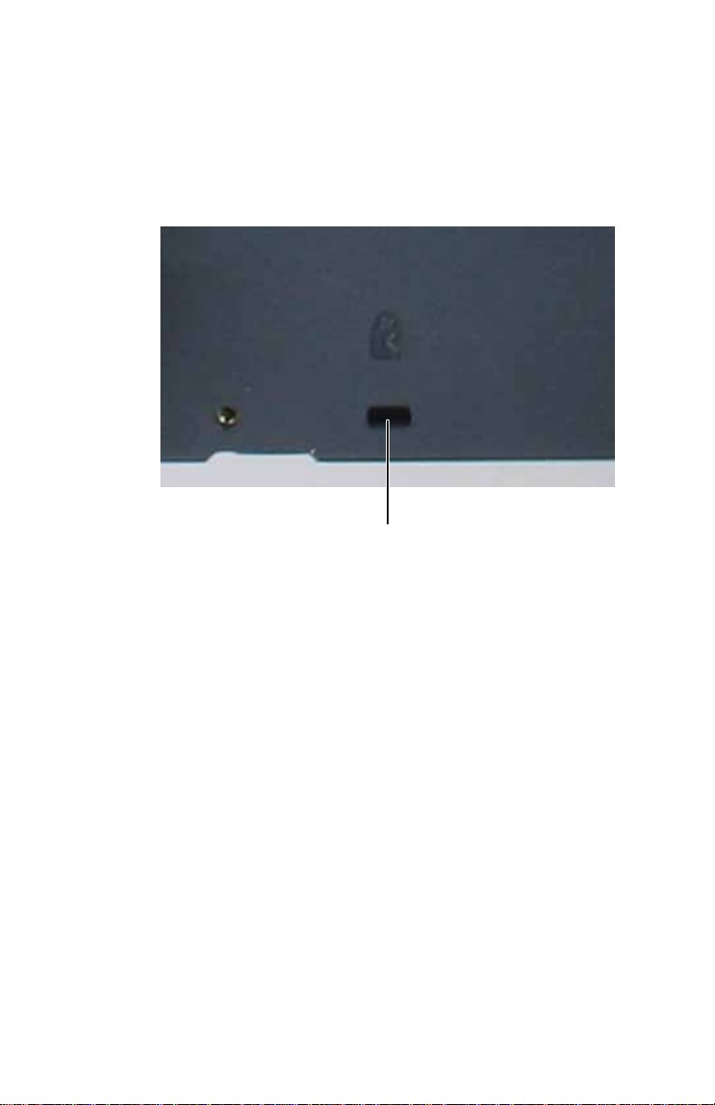
Connec ting a sec urity c able
Y ou can secure your monitor and speak e r bar to your desk (or
to ano the r h eavy ob je ct) w ith a c abl e l ock, such as a
Kensington™ lock. To connect a cable lock, follow the cable
lock’ s instructio ns to connect it t o the cable loc k slot on the back
of your monitor (cable lock not included).
Cable lock slo t
Preparing t he remot e control
Your monitor’s universal remote control comes with batte ries
that you must install before using it.
22
Page 29

www.gateway.com
To insta ll ba tteri es in to th e rem ote co nt rol:
1 Remove th e b a tte r y co m p a rt m e nt c ove r on th e b ack o f
the remote c ontrol.
23
Page 30

CHAPTER2: Setting Up Your Monitor
2 Insert the batteries while matching the + and - symbols
on the diagram inside the battery compartment, then
close the battery compartment cover.
Important
Your remote control works for your monitor, but you must
program it to work for your other devices (such as cable satellite set-top
boxes and DVD players). For more information, see “Programming the
universal remote control” on page 54.
24
Page 31

www.gateway.com
P ositioning the monit or
You can adjust the monitor for left and right pan and up and
down tilt angle.
25
Page 32

CHAPTER2: Setting Up Your Monitor
Ergonomic guideline s
The recommended screen positioning is based upon the
following guidelines. These guidelines are based on available
scientific literature and published standards.
Screen height
The recommended screen height f or displa ys (e xcept in spec ial
circumstances, such as for bifocal use) is that the top of the
display shoul d be set a t or slig htly bel ow (about 1 inch or
25mm) your eye level while you are sitting in a com fortable
working posture. This guideline places the cent er of the s creen
at an ideal 15° to 20° viewing angle for most desktop d isp l ays.
If the display has multiple users, the screen height should be
easily adjustable to accommodate each user’s height and
preference.
Screen tilt
The screen should be tilted so your line of sight is
perpendicular to the screen. This angle creates the most
consistent viewing distance when scanning fr om the top of the
screen to the bottom. You may need to adjust lighting to avoid
screen glare when the screen is tilted upward.
Screen distance fr om user
The screen should first be placed at arm’s length f rom the user,
then adjusted back and forth to suit individual preference.
26
Page 33

CHAPTER3
Using Y our Monit or
• Starting the monit or
• Using the EzTouch menu
• Adjusting monitor set tings
• Changing Windo ws sc reen s etting s
• Using the speake r bar
• Po wer management
• Maintaining
27
Page 34
CHAPTER3: Using Your Monitor
Starting the monit or
Caution
If you pla n to connect your monit or’s USB hub to the c omp uter’s USB port,
firs t in s tal l th e i ncl ud ed Ez Tune s oft ware on to yo ur co mp uter.
T ur ning on the monit or
To s t a rt t h e m o n i to r :
1 Touch the power button on the front of monitor. The
power LED on the power button changes from purple
(off) to blue (on), then turns amber/orange (standby) if
no video source is detecte d.
Tip
For more information on using your monitor’s touch buttons, see
“Using the EzTouch menu” on page29.
28
Power butto n
2 T ur n on your computer. After your computer is running,
the power LED on the monitor’s pow er butt on should be
blue, indicating that the monitor has detected a video
source. Allow about 15 seconds for th e display image to
appear.
If you do not see an image after waiting 15 seconds,
check the color of the power button light.
• No light—The monitor is not receiving power. Make
sure that the monitor is plugged into an AC outlet.
• Purple—The monitor is turned off. Press the power
butto n to tu rn i t o n.
Page 35

www.gateway.com
• Amber—The monitor is not de t ec ting a v ideo source.
Check the video input connections and make sure
that the computer is turned on and connected
corre ctly to t he mon ito r.
• Blue—The monitor is detecting a vi deo source.
For more troubleshooting information, see
“Troubleshooting” on page43.
Tip
The first prompt you see is the language selection menu settin gs.
You must select a default language for the OSD before you can proceed.
To modify the langua ge you se lect at a future tim e, use the Advanc ed
menu. If you cannot access the Advanced menu because you chose a
language you cannot read, do the following:
• Unplug th e monito r fro m the power outlet for ten o r m o re seconds.
• Plug the monitor back into the power outlet.
You will be prompted for the language selection menu settings again.
Important
If you turn on the monitor and no video inputs are conne cted, t he
product tour starts. To disable the product tour, see “Power
management” on page41.
3 Adjust the t ilt o f th e mo ni tor for the b es t viewing an gl e.
4 For VGA input only: After you see the Windows
desktop, touch (Menu) on the front of your monitor,
then touch (Auto) to auto ma ti cal ly a dj ust your
display image to the ideal settings.
5 Use the on-screen display (OSD) to adjust other monitor
settings. For more information , see “Using the EzTouch
menu” on page 29.
Using t he EzT ouch menu
This monitor features an on-screen display (OSD) and EzTouch
menu buttons that let you adjust settings. Your monitor saves
the settings, e ven if y ou turn off the monitor. Your monitor ha s
two lev els of menus, and the func tionality of t he touch but tons
depends on the menu that is currently open:
• The shortc ut menu (the first menu that appears) lets y ou
quickly change some of the most commonly accessed
settings.
• The main menu lets y ou acce ss all of the func tions of t he
display and precisely adjust all levels of settings.
29
Page 36

CHAPTER3: Using Your Monitor
Using the sh ort cut menu
To use the shortcut menu:
Tip
To use an EzTouch menu button, lightly touch it.
1 Touch (Menu) on the front of your monitor . The rest
of the buttons light up and the shortcut menu opens.
(The menu’s appearance and choices v ary, depending on
the currentl y active video input and whether the speaker
bar is attached.)
Volume Adjust
Mute
Information
Vide o S c a l i ng
30
Input Select
Cancel
Main Men u
• Slide your finger up or down the (Volume Adjust)
button area to increase or decrease the volume level.
• Touch (Mute) to mute all sound.
• Touch (Information) to see inf ormation about the
current v ideo source. The ty pe of information you see
varies based on the type of video source.
• Touch (Video Sca ling ) to scale images to fill the
screen. For more informati on, see “Video Adjust
menu” on page 35.
Page 37

www.gateway.com
• Touch (PIP On) to turn on Picture-in-Picture, and
press (PIP Settings) to ad just the PIP p osit ion ,
size, and other advanced PIP settings. PIP
adjustments may also be made using the included
EzTune software. You must have multiple video
sources connected for these options to be available.
PIP is onl y available whe n DVI is selec t e d a s t he main
input and the display is set to 2560 x 1600 (dual-link
DVI connection required.
Tip
PIP On and PIP Settings are only a v ailable when a Dual-Link DVI
source is connected.
• Touch (Input Select) to swi tch to ano the r
available video source.
• Touch (Cancel) to exit the short cut menu. You can
also wait abo ut 30 se conds without pressing a
button, after which the menu closes by itself.
• Touch (Main Menu) to open the main menu.
Important
The button functions change depending on the menu you are in.
31
Page 38

CHAPTER3: Using Your Monitor
Using the main menu
To use the main menu:
1 Touch (Menu) on the front of your monitor . The rest
of the buttons light up and the shortcut menu opens.
Choose Option
Select
Menu Off
32
Important
The EzTouch menu buttons are very sensitive, and may be
“pressed” by holding your finger just above their surface. To completely
“release” a touch button, make sure that you lift your finger well away
from the button .
2 Touch (Main Menu) . The main menu opens.
Tip
While the OSD is active, on-screen labels appear next to the
buttons to he lp you i de nt if y th em .
You can se lect from th e fol lowin g sett ing s:
• Auto—Automat icall y opt imiz e s the monit or’ s dis pla y
setti ngs to m atch the sel ecte d vi de o s ourc e.
• Picture—Lets you change Brightness, Sharpness,
Contrast, Gamma, Black Level, Saturation, and
Hue settings.
Page 39

www.gateway.com
• PIP Settings—Lets you change the PIP po sition, si z e ,
and other advanced PIP settings.
• Vi deo A djust —Lets you change Theme Mode,
Color Temp, and Vide o Sca ling settings .
• Geometry—Lets you change Horizontal Position,
Ver ti ca l Po si ti on , Clock, and Phase settings.
• Audio—Lets you change Volume, Bass, Treble, 3D
Audio, Audio Source, Auto Delay, and Manual
Delay settings.
• Advanced—Lets you change Color, Language, LED
Mode, DVI Video Mode, Resolu t i o n Re mi n d e r, IR
Training, Auto Inp ut D etec tion , Integrated
Product Tour, and Information settings.
• Reset— Resets a ll sett ings to their factory defau lts.
Tip
For more detailed explanations of the menu choices, see
“Adjusting monitor se ttings” o n pag e 33.
3 Touch one of the ( Choose Option) b utto ns to
highlight a setting, then touch (Select) to open the
selected menu or setting.
4 T ouch one of the (Adjust) buttons to adjust the setting
or change the option.
5 Touch (Back) to re tu rn to a p revio us me nu.
6 When you have finished making all adjustments, touch
(Menu Off) to exit. Your changes are saved.
Adjusting monit or set tings
Use the monitor controls (located on the monitor itself) and
computer controls (accessible through Windows) to adjust the
display image. For more inf ormation about computer controls,
see “Changing W indows s creen s et tings” on page38. For more
information about monitor controls, see “Using the EzTouch
menu” on page 29.
Tip
Many common settings for VGA, DVI, and HDMI (PC only) can also be
adjusted and controlled using the EzTune software included with your monitor.
After installing EzTune, see the program’s online help.
33
Page 40

CHAPTER3: Using Your Monitor
Using monit or menu s
Use the monitor’s on-screen display (OSD) menus to change
settings and sele ct inputs .
OSD Menu Description
Main menu
Pictur e menu
Auto—Automatically adjusts your monitor to its optimum
settings. (VGA input only)
Picture—Ope ns the Picture menu, where you can adjust
brightness, c ontrast, a nd gamm a.
PIP Settings—Opens the PIP Settings menu, where you can
adjust the source, position, size, and transparency of the
Picture-in-Picture image.
Video Adjust—Opens the Video Adjust menu, where you can
adjust the RGB (red, green, and blue) values of the video image
from a source such as composite video, S-Video, or component
video.
Geometry—Opens the Geometry menu, where you can adjust
image size and minimize distortions.
Audio—Opens the Audio m enu, where you ca n adjust v olume ,
bass, treble, 3D audio, audio source, auto delay, and manual
delay.
Advanced—Opens the Advanced menu, where you can adjust
color balance, change the OSD language, and display
information about current monitor sett ings.
Reset— Rese ts the m oni to r to it s fa cto ry se tti ngs for th e
currently displayed input.
Brightness—Adjusts the amount of light in all portions of the
picture. Us e t he lo w est brightne s s s et ting y ou are c omf or table
with to maximize the life of the monitor backlights. You may
need to readjust brightness afte r the monitor warms up.
Sharpness—Adjusts the clarity of the image.
Contrast—Adjusts the le vel of white between the lightest and
darkest portions of an image.
Gamma—Customizes the gamma level. High gamma levels
increase white levels and low gamma levels increase contrast.
Black Level—Adjusts the brightness level in the darkest part
of the image.
Saturation—Adjusts the intensity of a hue. High saturation
results in very bright, vivid colors. Low saturation results in
grayish colors.
Hue—Adjusts the color spectrum of the display.
34
Page 41

OSD Menu Description
www.gateway.com
PIP Settings
menu
Video A djust
menu
PIP Display—Toggles the di spl ay of th e PIP wi ndow.
PIP Source—Sets the source of the video used in the PIP
window.
PIP Position—Sets the position of the PIP window on the main
screen.
PIP Size—Sets the size of the PIP window.
PIP Transparency—Sets the transpar en cy of the PIP window.
When the PIP window is transparent, you are able to see
through the P IP vi deo displa y t o your W indo w s desk t op, w hich
makes it easier to access your computer programs while
watching video.
PIP Full or PIP Restore—Makes the PIP image full scr e e n and
restores the PIP to its original size.
PIP Picture—Opens a menu where you can set the PIP
brightness, contrast, sharpness, black level, saturation, and
hue.
Important: PIP is only available when you are displaying PC
input as the main input and the monitor is set to 2560 x 1600
(dual-li nk DVI conne ction requ ired) .
Unless otherwise indicated, these settings apply only to SD
(standard definitio n) video at 4 80i and below . Wher e “PC inpu t”
is indicated, the resolutions that apply are from 800× 600 to
2560 × 1600.
Theme Mode - Activates the built-in color engine to enhance
the graphic effects according to what is displayed on the
screen. Choose from Web, Game, Movie, Picture, or Custom.
Color Temp – Adjusts the tints of the colors in the picture.
Choose from Cool, Neutral , and Warm
Sharpness—Adjusts sharpness for video images.
Film Mode Detection—Film Mode Detection detects frame
rates of the source image and adapts the frame rate of the
display for ultimate image quality. Bad Edit Detection and
Correction co rrects inc orrectly synchro nized video.
35
Page 42

CHAPTER3: Using Your Monitor
OSD Menu Description
Video Adjust
menu (cont)
Video Scaling—Sets video aspect ratios and scaling between
Wide, Zoom, and 1:1 modes. PCin put: sets resoluti on aspect
ratios and scaling between Wide, Zoom, and 1:1.
Wide mode stretches a standard
broadcast or f ull-frame image to fi ll
the entire screen. Widescreen
(1 .76:1) ima ges fi ll th e entir e s c re en
without distortion, while
widescreen (1.85:1 and 2.35:1)
images appear without distortion but with black bars at the
top and bottom. PC input: Stretches the ima ge to fit the enti re
screen.
Zoom mode cr ops off a port ion of a
widescr een image in order t o fill the
entire screen with a distortion-free
and black bar-free image. PCinput:
Zooms the image to fill the screen
from top to bottom with black bars
on the left and right sides of the image.
1:1 mode preserves the movie’s original
aspect ratio, so a standard broadcast or
full-frame mo vie appears with black bars
on the l eft and righ t of the ima ge.
PCinput: Preserves the original aspect
ratio of the resolution by using black bars
on the left and right sides and variable sizes of black bars on
the top and bottom of the image (depends on resolution).
36
Noise Reduction—Uses noise reduction filters that adapt to
the amount of noise and motion from the video source.
Cross Color Reduction—Reduces cross-color artifacts, such as
unintentional flashing colors or rainbow patterns, that result
from composite video signals.
Overscan—A video signal is often displayed slightly cut off at
all edges. If Overscan is turned off, you may notice strange
video anomali es on the edge s of the video bein g displ ayed.
This is normal and is part of the data embedded in any video
signal. To avo id seeing these anomalies, turn Overscan on.
Page 43

OSD Menu Description
www.gateway.com
Geometry
menu
Audio menu
Horizontal Position—Moves the display image left and right.
You can also press the Auto button to configure the vertical
and horizontal position automatically. Important: Auto only
works with VGA input.
Vertical Position—Move s the display im age up anddown. You
can also press the Auto button to configure the vertical and
horizontal position automatically. Important: Auto only
works with VGA input.
Clock—Minimizes any vertical bars or stripes visible on the
screen bac kgr ound. The hori zontal screen si ze will also change .
Gateway recomm ends that you do not a djus t the Clock
setting.
Phase—Minimizes any horizontal distortion and clears or
sharpens the displa ye d char ac te rs. Gat ew a y r ecommends that
you do not adjust the Phase setting.
Volume—Adjusts volume.
Bass—Adjusts bass tones.
Treble—Adjusts treble tones.
3D Audio—Enables simulated surround sound.
Audio Source—Selects the audio source. Allows the audio
source to be set to the main or PIP window. When set to PIP
window and the PIP is displayed on screen, the audio being
played switches from the main to the PIP window. When the
PIP window is closed, the main audio is heard. When set to
main, PIP audio is only heard when the PIP is set to full screen.
Auto Delay—Automatically adjusts the audio to be in sync
with the video. Audio and video may be out of sync due to the
time it takes to process the video information verses the time
it takes to process the audio information.
Manual Delay (ms)—If auto delay does not adequately sync
the audio and video signals, you can manually sync the two
signals. The audio delay can be adjusted in milliseconds.
37
Page 44

CHAPTER3: Using Your Monitor
OSD Menu Description
Advanced
menu
Color—Customizes the color levels.
Language—Changes the language of the OSD.
LED Mode—Change s the brightne ss of the Me nu, Standby , a nd
Power LED to Day Mode or Nite Mode. When watching movies
in a darkened room, you may want to change the LED mode
to Nite Mode to avoid an over-bright, distracting power LED
indicator.
DVI Video Mode—Changes the DVI video mo de by enabl ing
either RGB Color Space (used for digital input) and YUV Color
Space (used f or analog TV input such as NT SC , P AL, and SE CAM).
IR Training—Trains other universal remote controls to learn
the IR comma nds that cont rol the mon itor fea tures. Use thi s
option if you prefer not to use the included monitor remote
control.
Input Search—Enables automatic se arching for valid vid eo
inputs. If set to dis abl ed, you must manuall y change the input
using the touch pad or remote control. If set to enabled, the
monitor aut omatically s earche s for an ac tive input and displa ys
it when one is found.
Integrated Product Tour—Enables the product tour. If set to
enabled and if there are no active video inputs found, the
display aut om atical ly s tar ts t he pr od uct t our when th e displa y
is turned on. After watching the product tour, you should set
this featur e to disabled. You can watch the product tour again
by pressing and holding the Menu button for thre e sec onds .
Resolu tion Remind er—If the computer display input (VGA,
single-link DVI, or HDMI-PC only) is not set to 1920× 1200 or
if the computer display input (dual-link DVI) is not set to
2560× 1600, display s a remind er that y ou should chan ge your
computer’s settings to use the optimum 1920× 1200 or
2560× 1600 resolution. If you prefer using your monitor at a
resolution less than the optimum, use this option to turn off
the Resolution Reminder. For information on changing your
computer’s di spl ay resolution, see “Changing Window s s creen
settings” on page 38.
Information—Displ ays current screen resoluti on an d input
source for the main display.
Reset All— Resets a ll valu es to th e factory settin gs.
Changing Windo ws s creen s ettings
Color depth and screen resolution are two of the most basic
moni tor sett ing s yo u may ne ed to ch ang e to su it your ne ed s.
Color d epth is the number of colors your computer uses to
display images on your monitor. Most images look best
displayed wit h the maximum number of colors av ailable. If the
color in your images seems “false” or “jumpy,” especially after
you have played a game or run a video-intensive program,
check the color depth setting and return it to the highest color
setting, if necessar y.
38
Page 45
www.gateway.com
Screen resol utio n is the number of pixels (individual colored
dots) your computer uses to display images on your monitor.
The higher the resolution, the more information and screen
components (such as icons and menu bars) can be displayed
on the monitor.
Important
To use the monitor’s full (highest) resolution (2560× 1600), you must use
the included dual-link DVI cable to connect the monitor to a dual-link capable
video card on your computer.
A single-link DVI cable or video card limits resolution to 1920 × 1200.
VGA and HDMI connections are also limited to 1920× 1200 resolution.
Tip
If the vi deo i mage appe ars c orrupt o r garble d af t e r y ou c ha nge resolution
settings, your video card may not be capable of supporting the selected
resolution.
Help
For more information about adjusting the screen, click Start, then click
Help and Support. Type adjusting monitor setting s in the Search Help
box, then press E
NTER.
To change the color depth and screen resolution in
Windows Vista
®
:
1 Click (Start), Control Panel, then under Appearance
and Personalization, click Adjust Screen Resolution.
The Display Settings dialog box opens.
Shortcut
You can also right-click on your Windows desktop, then click
Personalize.
2 T o change the color depth, c lick t he Colors list, then click
the color depth you want.
Color quality settings:
• Low (8-bit) = 256 colors
• Med ium (16-bit) = 65,500 colors
• Highest (32-bit) = 16,700,000 colors
3 To change the screen resolution, drag the Resolution
slider to the size you prefer.
4 Click Apply. If the new settings do not look right, click
No. If the new settings make t he scr een illegible and you
cannot click No, the settings return to their previous
values after several seconds.
5 Click OK, then click Yes to save your cha ng es.
39
Page 46

CHAPTER3: Using Your Monitor
To change the color depth and screen resolution in
Windows XP:
1 Click Start, then click Control Panel. The Control Panel
opens. If your Control Panel is in Category View, click
Appearance and Themes.
Shortcut
You can also right-click on your Windows desktop, then click
Properties.
2 Click Display. The Di splay Pro perties dialog box opens.
3 Click the Settings tab.
4 T o change the color depth, click the arrow button to open
the Color q uality list, click the color depth you want.
Color quality settings:
• Low (8-bit) = 256 colors
• Med ium (16-bit) = 65,500 colors
• Highest (32-bit) = 16,700,000 colors
5 To change the screen resolution, drag the Screen
resolution slider to the size you prefer. The optimum
resolution for your display is 2560 × 1600.
6 Click Apply. If the new settings do not look right, click
No. If the new settings make t he scr een illegible and you
cannot click No, the settings return to their previous
values after several seconds.
7 Click OK
Using t he speaker bar
Important
If you connect the speaker bar to the monitor while the monitor is turned
on, the speaker bar will not initialize and will not work correctly. If this happens,
turn the monitor off, then back on to enable the speaker bar.
To turn on the speaker bar:
• The speaker bar is always on. If you connected the
speaker bar by following the instructions in “Setting up
the optional speaker bar” on page19, the speaker bar
receives power constantly from the monitor’s speaker
bar power connector.
40
Page 47

www.gateway.com
To use headphones :
• Plug headphones into either of the speaker bar’s
headphone jacks. The speaker bar’s volume is muted,
and sound is played through the connect ed headphones.
You can connect headphones to both headphone jacks,
and sound plays out of both sets of headphones.
P ower man agement
Whenever no v ideo signal is det ect ed b y your monit or , it ent ers
Standby mode, a mode that uses very little power. When in
Standby mode, the power button turns orange. Turning off
your computer stops its video signal to the monitor, so if your
computer is the only video source connected, your monitor
enters Standby.
If the monitor does not enter Standby, and instead displays a
prompt for the product tour, you should disable the product
tour.
To disable the product tour a nd enable Sta ndby mode:
1 Touch (Menu), (Main Menu), then touch
2 Touch one of the ( Adjust) b utto ns to se lect
(Advanced).
Integrated Product Tour, then press (Select) to
disable the tour.
Energy declar ation
When connected to a computer t hat supports the VES A Display
Power Management Signaling (DPMS) Protocol, the monitor
can conserve significant energy by reducing power
consumption during periods of non-use. When your computer
goes into the energy sav i ng mode , the monitor will then enter
the ActiveOff mode (sleep) . In the ActiveO ff mode the Power
LED will still show orange.
Use these conventions and the power can be reduced to the
following levels:
VESA St ate LED Indicator Power Con su mpt io n
On Blue ≤168 W
Standby Amber ≤19 W
Off Purple ≤19 W
41
Page 48

CHAPTER3: Using Your Monitor
To “wake” the monitor when it is in Standby/Active Off mode,
move the mouse or press any keyboard key. You can change
the monitor’s pow er management settings u sing the W indows
Control Panel. For more inf or mation, see your computer’s Us er
Guide.
Maintaining
To keep the monitor in optimal working order:
• Do not block the ven tilation holes.
• Do no t exp ose the mon ito r to rai n o r us e n ea r wa ter.
• Keep the monitor away from radiators or heat vents.
• Keep the monitor out of direct sunlight.
Caution
Do not use any type of abrasive pad or glass cleaner. You will
permanently scratch the screen.
• To clean the monitor, use a soft cloth slightly moistened
with water only. Wipe the cabinet, screen, and controls.
42
Page 49

CHAPTER4
Troubleshooting
• T rouble shooting guidelines
• T rouble shooting sympt oms
• HDCP FAQs
• Video FAQs
43
Page 50

CHAPTER4: Troubleshooting
T r oubleshooting guidelines
• If you have problems with the monitor, the information
in this chapter may help you solve them without needing
to ca ll Cu stom er Ca re.
• Make sure t hat the monitor ha s w armed up f or about 30
minutes before making any judgments about the picture
quality.
T r oubleshooting sy mptoms
No power
• Make sure that the power cord is connected correctly to
both the ba ck o f th e m on itor an d th e wa ll ou tlet . F or
more information about connec ting the pow er cord, s ee
“Connecting power” on page17.
Important
If the power LED is on, the monitor is receiving power.
No picture
44
• Touch (Menu), then touch (Input Select) to make
sure that you have selected the correct video source.
• Make sure that the power cord is connected correctly to
both the ba ck o f th e m on itor an d th e wa ll ou tlet . F or
more information about connec ting the pow er cord, s ee
“Connecting power” on page17.
• Make sure that the video cable is connected securely to
the back of the monitor and computer. For more
information ab out c onnectin g the vid eo cabl e, see
“Connecting video inputs” on page12.
• Make s ure tha t th e m on ito r i s tu rn ed on .
• Reset the mo nito r to th e factor y se ttin gs. For m ore
information, see “Advanced menu” on page 38.
Page 51

www.gateway.com
• If the power LED is orange, it means that the monitor is
not detecting a video source or input detection is
disabled. Complete the following steps:
• Move the mouse or press any key on the keyboard
to bring the computer monitor out of sleep mode.
• Press Input on the remote control to choose another
input or touch (Menu), then touch (Input
Select) to choose another input.
• Make sure that your computer is turned on.
• Restart your computer with the monitor turned on.
• Make sure that the video cable is not damaged.
• Check the end of the video cable for any pins that
might be bent or pushed in .
• Reset the OSD. For more information, see “Advanced
menu” on page 38.
Important
If the monitor is not detecting a video signal, you will see a “No
Signal” message on the display followed by a “No Input Detected”
message. At this point, a video tutorial will play.
• T urn off the monitor and unplug the video cable from the
back of your computer. Turn the monitor back on and
wait for ten seconds. If the monitor is functioning
correctly, a “No Signal” message appears. For more
information ab out c onnectin g the vid eo cabl e, see
“Connecting video inputs” on page12.
You have the monitor connected to your notebook’s VGA port but see no image on the screen.
• If your notebook supports dual displays, you can use
both your notebook’s display and this monitor in
extended desktop multi-monitor mode. See Windows
Help to learn how to enable multiple monitors.
• You can also use this monitor as your primary monitor
and not use the notebook’ s sc reen. Notebook computers
typically ha ve an F
between your notebook’s display and an externally
attached display. On Gateway n otebooks, this key
combination is F
top row of keys. See your notebook user guide for more
information.
N ke y combination t hat lets y ou tog gle
N+F4. The F4 key i s l o c a te d al o n g t h e
45
Page 52

CHAPTER4: Troubleshooting
Display colors ar e wrong
• Touch (Menu), (Ma in Menu), then (Auto) to
autom at ica ll y ad jus t th e d is pl ay i mag e to th e
ideal settings. (VGA input only.)
• Restart your computer with the monitor turned on.
• Make sure that the video cable is connected securely to
the back of the monitor and your computer. For more
information ab out c onnectin g the vid eo cabl e, see
“Connecting video inputs” on page12.
• Make sure that the video cable is not damaged.
• Check the end of the video cable for any pins that might
be bent or pushed in.
Pic ture has shado ws or “ gho sts”
• Touch (Menu), (Ma in Menu), then (Auto) to
autom at ica ll y ad jus t th e d is pl ay i mag e to th e
ideal settings. (VGA input only.)
• Remove any exte nsion cables or switchboxes.
• Make sure that the video cable is connected securely to
the back of the monitor and your computer. For more
information ab out c onnectin g the vid eo cabl e, see
“Connecting video inputs” on page12.
• Make sure that the video cable is not damaged.
• Check the end of the video cable for any pins that might
be bent or pushed in.
• Make sure t hat your monitor connection is u sing the VG A
cable that came with your monitor.
Color is not unif or m
• Touch (Menu), (Ma in Menu), then (Auto) to
autom at ica ll y ad jus t th e d is pl ay i mag e to th e
ideal settings. (VGA input only.)
• Make s ure tha t th e m on itor war ms u p fo r a t l eas t
30 minutes before making a final judgment about color
uniformity or brightness.
46
Page 53

www.gateway.com
Image is not siz ed or cent ered correc tly
• Touch (Menu), (Ma in Menu), then (Auto) to
autom at ica ll y ad jus t th e d is pl ay i mag e to th e
ideal settings. (VGA input only.)
• Use the position controls to adjust the image. For
instructions on ho w to adjust th e display image po sition,
see “Adjusting monitor settings” on page 33.
If you see black bars on left and right of the screen and wan t to st re tch th e vi de o t o fi t m or e o f t he sc re en :
• Touch (Menu), (Main Menu ), (Video Adjust),
then touch (Video Scaling). T o fill more of t he screen ,
choose Wide, Zoom, or 1:1 modes.
Bad pictur e
Important
To use the monitor’s full (highest) resolution (2560× 1600), you must use
the included dual-link DVI cable to connect the monitor to a dual-link capable
video card on your computer.
A single-link DVI cable or video card limits resolution to 1920 × 1200.
VGA and HDMI connections are also limited to 1920× 1200 resolution.
The image looks stretched or fuzzy when you connect the moni tor to yo ur c omp uter
• You must ad j ust the operatin g system’s display settings
to match the m oni tor ’s op tim al ( native) 2560 × 1600
setting (available only on systems using a dual-link DVI
cable attached to a dual-link DVI-capable video card).
VGA, HDMI, or a single-link DVI cable or video card have
a maximum resolution on this monitor of 1920 × 1200.
For information on adjus ting settings in Windows, see
“Changing Windows screen settings” on page38.
You do not see 2560× 1600 available in the Windows
display control panel
• Make sure th at your video card can display at
256 0× 1 600 re solution. If y ou ha ve onl y a single-link D VI
cable or video card, the maximum resolution you can
display on this monitor is 1920× 1200.
• Make sure that you are using either the DVI cable that
came with your monitor or a third party cable that is
dual-link capable.
• Some video cards th at have two DVI p orts su pport
dual-link on one of the DVI ports. T urn of f your computer ,
move the DVI cable to the altern ate DVI port, then re start
your computer.
47
Page 54

• This may be caused by older video drivers on your
computer. See the Gateway supp ort Web site at
www.gateway.com
computer. You can also go directly to your video card’s
support Web site for the most up-to-date video drivers.
The Web sites for the major video card manufacturers
are:
®
ATI
Intel®: www.intel.com
Nvidia®: www.nvidia.com
You see “noise” or “trash” on the screen
• The signal on HDMI or DVI-D may be HDCP encoded. If
the signal is not decoded correctly, the video either
flashes or shows colored snow.
• Make sure that the output device is directly plugged
into the monitor (remove any video
switchers/receivers).
• Unpl ug the HDMI or DVI cable to reestablish a
connection with the output device.
• Stop and restart the output device to allow
renegotiation.
Gaming support
CHAPTER4: Troubleshooting
for updated video drivers for your
: www.ati.com
48
Your games do not have support for widescreen displays.
• Newer games are adding support for widescreen
displays as the widescreen format beco mes more
popular. C heck the game’ s W eb site f or update s. You can
also consu lt the following Web site for specific settin gs
and options to configure older games to support
widescreen: www.widescreengamingforum.com
adjustments may require you to make changes to the
Windows System Registry. We recommend making a
complete system backup before changing the System
Registry.
. Some
Page 55

www.gateway.com
The monit or has pi xels t hat are alw a ys dark or too bright
• This condition is normal and inherent in the TFT
technology used in activ e-matrix LCD scr eens. Gatewa y’s
inspection standards keep these to a minimum. If you
feel these pix els are unacceptably numerous or dense on
your displa y, contact Gatew a y Customer Care to identify
whether a repair or r eplacement is justified based on t he
number of pixels affected.
Speake r bar does not work
You installed the speaker bar, but no sound is coming out of the speakers.
• Make sure that the speaker bar power cord is plugged
into the powe r c on ne ctor on t he bac k o f you r mon ito r
and that the monitor is plugged into an A Cpower outlet.
• Make sure that the speaker bar’s audio cable is plugged
into the speaker bar audio jack on the back of your
monitor.
• Make sure that the cable from the audio output jack on
your device is plugged into the correct audio input jack
on the monitor. For more information, see “Connecting
audio inputs and outputs” on page 14.
• If you are using HDMI audio, you must set your device
to output audio in PCM mode. See the user guide that
came with your device for more information.
• If you just finished installing and connecting the speak er
bar, restart your monitor so that it can recognize the new
speaker bar.
• Make s ure tha t th e v olu me is tu rne d u p.
• Make sure that headphones are not plugged into the
headphone jacks on the sides of the speaker bar. When
headphones are connected, no sound comes out of the
speaker bar’s speakers.
• Your headphone/speaker jack may have been muted
using Windows sound controls. To check your
headphone/speaker mute settings, click the speaker
icon in the Window s tas kbar, or click (Start), Control
Panel, Sounds and Audio Devices, the Volume tab,
then click Advanced. For optimum volume control u sing
the spea ker bar, we recommen d that you set the
Windows volume mid-way between the lowest and
highest setting.
49
Page 56

CHAPTER4: Troubleshooting
You want to plug in your headphones, but there is a headphone jack on bo th sides of the speaker bar.
• You can use either jack or both jacks at the same time.
When headphones are connected, no sound comes out
of the speaker bar’s speakers.
You do not get sound from your headphones.
• Make sure t hat your speaker bar is connec ted to an audio
source by unplugging your headphones and adjusting
the speaker bar ’s volume.
The sound coming from the speakers sounds distorted.
• Turn down the volume until the distortion disappears.
• Check the audio output volume of the sound device the
speaker bar is connected to. If the audio device’s output
volume is set too high, the speaker bar’s sound may
always be distorted. To adjust the audio device’s output
volume , see the de vice’ s user guid e. T o adjust t he volume
in Windows, click the sp eaker icon in the Windows
taskbar, or click (Start), Control Panel, Sounds and
Audio Devices, the Volume tab, then click Advanced.
For optimum volume control using the speaker bar, we
recommend that you set the Windo ws volume mid-way
between the lowest and highest setting.
HDCP F AQs
What is HDCP and how do I troubleshoot it?
• High-bandwidth Digital Content Protection (HDCP) is a
specification develope d by the Intel
protect digital entertainment content that uses a digital
visual interface (DVI) , including HDMI connections.
HDCP encrypts the transmission of digital content
(signal) between the video source (comput er, D VD player ,
or set-top box) and the digital display (monitor, digital
telev ision, or projec t or). HDCP is not designed to pre v ent
copying or recordin g of digit al content, but only to
prote ct th e i nteg rit y o f th e c on ten t as tra ns mi tted.
50
®
Corpora tion to
Page 57

www.gateway.com
How does HDCP work?
• Implementation of HDCP requires a license obtainable
from the Digital Content Protection, LLC, which then
issues a set of unique sec re t de vice keys to all author iz ed
device s. During a uthenticati on, the r ecei ving de v ice onl y
accepts content after it acknowledges the keys. To
further prevent stealing of the data or line tapping, the
transmitter and receiver generate a shared secret value
that is constantly chec ked throughout the transmission.
After authentication is established, the transmitter
encrypts the data and sends it to the receiver for
decryption.
What happens if I lose signal to the display while watching a movie on a HDCP-equipped component?
• The component must be restarted to establish
renegotiation.
For example , while watc hing a movie on a HDCP-enabled
DVD player, you change the receiving device (DTV,
monitor, or projector) input to watch broadcast TV, then
change the input back to w atch t he DVD mov ie. How ev er ,
you are unable to watch the movie. This is because when
the input was changed, the receiver lost the HDCP signal.
Restart the HDCP-enabled DVD player to allow
renegotiation.
My computer has an HD-DVD or Blu-Ray DVD player and I receive an error message when I try to play an HD or Blu-Ray DVD
• This issue occurs when you have you r PC desktop set to
2560 x 1600 (Dual-Link mo de) reso lution . Currently, PC
graphics cards are incapable of negotiating the HDCP
key while in Dual-Link mode. HDCP key negotiation is
required to play consumer High Definitions DVDs. To
resolve this issue, set your Windows desktop resolution
to 1920 x 1200 before playing your HD or Blu-Ray DVD.
For more information about adjusting settings in
Windows, see “Changing Windows screen settings” on
page 38.
What is the cause if a movie starts and then slowly fades to sta tic?
• The receiving device is not HDCP compatible or it is not
negotiating correctly. Restart the video source and
re-plug all video cables from the source to the monitor.
How do I know if a component is HDCP compliant?
• If the video source device does not have a DVI or HDMI
connection, it is not HDCP compliant.
51
Page 58

Vi deo F AQs
When I display video fro m S-Video, comp osite, or component, why does the video look overly compressed?
• See your video device user manual to adjust the video
or TV format output to 16:9. Setting this option to 4:3
results in compressed video. This is done differently on
all brands of video devices, so it is important that you
read your video device user guide or the help tools
within your video device’s software.
• You can also opt imize the vid eo scali ng settings in the
monitor. Touch (Menu), (Main Menu),
(Video Adjust) , then touch ( Video Scaling). To
change to the mode you want, choose Wide, Zoom, or
1:1 modes.
When I try t o use Pictu re in Pictur e (PIP), why can I not select other video inputs?
• PIP is availab le o nly when 2560 × 1600 PC vide o over
dual-link DVI is selected as the primary video source.
Can I connect my game console to this monitor?
• Yes. Using optional video cables you can connect your
game console directly to the monitor. Use Component
Video (YPbPr) or HDMI if yo ur game cons o l e s upports it ,
because this results in the best picture quality.
CHAPTER4: Troubleshooting
52
When playing D VDs or wat ching video sourc es, I sometimes see random black and white noise at the t o p of t he pic tur e.
• This information is known as the Vertical Blanking
Interval or VBI data. This is typically where information
such as sub-titles or closed captioning text is stored on
a video frame by frame basis. To remove this
information, Touch (Menu), (Main Menu),
(Video Adjust), then touch (Overscan) to se t t his
option to enabled. The video will slightly zoom to
eliminate this effect.
Page 59

CHAPTER5
Using the Univ ersal
Remote Control
• Programming t he univ ersal remot e control
• Using the IR Blaster
• Remot e control pr ogramming codes
53
Page 60

CHAPTER 5: Using the U niversal Remote Control
Progr amming the univ ersal remote control
You can program the remote control directly (by entering a
five-digit code) or by browsing codes.
To directly program the remote control with a code:
1 Press and hold the mode butt on (CBL/SAT, DVD, LCD, or
MEDIA CENTER) for the devic e y ou w ant t o pr ogra m for
about four seconds. The LED flashes twice, indicating
that the bu tton is rea dy to be pro gra mm ed .
2 Press the five-digit code for the device. Afte r the code is
entered, the LED flashes twice, indicating that
programming is complete.
If an invalid key or code is entered, or if ten seconds
passes w ithout a butt on press, pr ogramming mode ends
and the previous values are restored. The LED lights for
about a half second, then turns off.
To progr a m t he re mote control by browsing through the
most common codes:
1 Press and hold the mode butt on (CBL/SAT, DVD, LCD, or
MEDIA CENTER) for the devic e y ou w ant t o pr ogra m for
about four seconds. The LED flashes twice, indicating
that the bu tton is rea dy to be pro gra mm ed .
2 Press 991, then press the digit that corresponds to the
type of device you want to associate with that mode’s
button:
54
Device type Digit
LCD 0
DVD 1
CBL/SAT 2
Media Center 3
Tuner 4
The remote is temporarily programmed with the first
most common code for the selected device type.
Page 61

www.gateway.com
3 Press the co ntro l b utto ns (p owe r, Vol+, play, stop, and
Mute) to test whether the current code is valid. If the
buttons work as they should, press the mode button you
pressed in step 1 once to save the code. The LED blinks
twice. You are done.
- OR If the buttons do not work as they should, press CH+ to
temporaril y prog ram t he nex t mo st common code, then
press the control buttons again. Keep pressing the test
and CH+ butt ons until you f ind a code that w orks. When
you find a working code, press the mode button you
pressed in step 1 once to save the code. The LED blinks
twice, and you are done.
Resetting the remote control
You can clear all programming and reset all remote control
setti ngs to th eir facto ry de faul ts .
To reset the remote control:
1 Press and hold a mode button (CBL/SAT, DVD, LCD, or
MEDIA CENTER) for about four seconds. The LED flashes
twice.
2 Press 977 . The LED flashes four times indicating that the
remo te c ont ro l is rese t to its facto ry de faul ts .
Recording with the remote control
Y ou can use the universal remote control to record vi deo from
a compatible recordable video device. To prevent the
accidental recording of video, you must press the record
button twice before recording can start.
To record a program:
1 Press and hold a mode button (CBL/SAT, DVD, LCD, or
MEDIA CENTER) for the devi ce you want to recor d from.
2 Press the record button. Recording begins.
Detecting low batteries
Your remote control’s batteries can last several months of
standard use, but you will need to replace them from time to
time with fresh batteries.
55
Page 62

CHAPTER 5: Using the U niversal Remote Control
To test you r re mote c ont rol ’s batte ries :
• Press and release any button on the remote control. If
the b atte rie s n ee d to be rep la ced , t he L ED fl ash es f ive
times.
Important
Whil e the b atter ies are lo w, the remote con trol can not enter
programming mode.
Using t he IR Blast er
You can use the provided IR Blaster cable to control a device
such as a DVD player, cable or satellite box, or computer with
a Windows Media Center IR r eceiver . B y using the IR Blaster , y ou
can place the device in an out of the way location where you
do not normally have line-of-sight with the remote control.
Important
Do not connect t he IR Blast er unt il af ter y ou ha ve progra mmed th e remot e
control for the device you want to control. For more information, see
“Programming the universal remote control” on page 54.
To connect the IR Blas ter:
1 Plug the IR Bl as ter in to th e IR B la ste r c on ne cto r lo c ate d
on the back of the monitor. For the location of the IR
Blaster connector, see “Monitor connections” on page 5.
2 Peel the backing off of the double-sided tape that is
attached to the IR Blaster emitter.
3 Stick the emitter over the IR receiver on the devi ce you
want to con trol .
56
To u s e t he I R B la s te r :
1 Point the remote control at the monitor, then press the
mode button for the device you want to control. (For
example, if you want to pause the DVD player, press
DVD.)
2 Press the control button for the device. (For example,
press the pause button.) The monitor rebroadcasts the
com man d from the remo te co ntro l to th e devi ce.
Page 63

www.gateway.com
Re mote contr ol progr amming codes
Defa ult dev ice ID code s
Y our remot e control has t he f ollowing codes pr ogrammed into
it from the fa ctory:
Remote control mode Default device Code
LCD
DVD
CBL/SAT
Media Center
T ele vi sion codes
Gateway XH D30 00 01756
Sony 10533
General Ins trum ent 20476
31272
Admiral
Advent
Aiko
Akai
Albatron
America Action
Anam
AOC
Apex Digital
Audiovox
Aventura
Bell & Howell
Bradford
Broksonic
Candle
Carnivale
00093, 00463
007 6 1, 007 83, 0081 5,
00817, 00842
00092
00812, 00702,
00030, 00672
00700
00180
00180
00030
00748, 00879, 00765
00451, 00180,
00092, 0080 2, 008 75
00171
00154
00180
00236, 00463
00030
00030
Memorex
MGA
Midland
Mitsubishi
Monivision
Motorola
MTC
Multitech
NAD
NEC
NetTV
Nikko
Norcent
NTC
Onwa
Optimus
00154, 00463,
00150, 00178
00150, 00178, 00030
00047, 00017, 00051
00250, 00093,
01 250, 00 150, 00 1 78,
00 8 36 , 01171, 0 1182
00700
00093
00060, 00030
00180
00156, 00178, 00866
00156, 00030, 01704
01755
00178, 00030, 00092
00748
00092
00180
00154, 00250,
00166, 00650
57
Page 64

CHAPTER 5: Using the U niversal Remote Control
Carver
Celebrity
Celera
Changhong
Citizen
Clarion
Commercial
Solutions
Contec
Craig
Crosley
Crown
Curtis Mathes
CXC
Daewoo
Dell
Denon
Dumont
Durabrand
Electroband
Electrograph
Emerson
Envision
00054
00000
00765
00765
00060, 00030,
00092
00180
01447, 0 0 04 7
00180
00180
00054
00180
00047, 00054,
00154, 00451,
00093, 00060,
00702, 00030,
001 45, 00 1 6 6, 0 114 7 ,
01347
00180
00451, 00092, 0166 1,
00672
01080, 01178
00145, 00511
00017
00463, 00180,
00178, 0 0171, 0103 4
00000
01755
00154, 00236,
00463, 00180,
00178, 00171
00030, 00813
Optonica
Orion
Panasonic
Penney
Philco
Philips
Pilot
Pioneer
Polaroid
Portland
Prima
Princeton
Prism
Proscan
Proton
Pulsar
Quasar
RadioShack
RCA
Realistic
Runco
Sampo
00093
00236, 00 463, 01463
00250, 00051,
00 65 0 , 01168
00047, 00156,
00051, 00060,
00178, 00030, 01347
00054, 00030
01454, 00054,
00690
00030
00166, 00679, 00866
00765, 00865
00092
007 6 1, 00 78 3, 0081 5,
00817
00700
00051
01447, 00047, 01347
00178
00017
00250, 000 5 1, 00650
00047, 00154,
00180, 00178, 00030
01447, 0 0 04 7,
00090, 00679,
01047, 01147, 01247,
01347, 015 4 7
00154, 00180,
00178, 00030
00017, 00030
00030, 01755
58
Page 65

www.gateway.com
ESA
Fisher
Fujitsu
Funai
Futuretech
Gateway
GE
Gibralter
Go Video
GoldStar
Goodmans
Grunpy
Haier
Hallmark
Harman/Kardon
Harvard
Havermy
Helios
Hello Kitty
Hisense
Hitachi
Hyundai
Infinity
Insignia
Inteq
JBL
JCB
00812, 00171
00154
00683, 00809,
00853 , 01181
00180, 00171
00180
01755, 01756
01 447 , 0004 7 , 0005 1,
00451, 00178, 01347
00017, 00030
00886
00178, 00030
00360
00180
01034
00178
00054
00180
00093
00865
00451
00748
001 78, 0 1 1 45, 001 45,
01245
00849
00054
00171
00017
00054
00000
Samsung
Sansui
Sanyo
Scotch
Scott
Sears
Sharp
Sheng Chia
Sony
Soundesign
Squareview
SSS
Starlite
Superscan
Supreme
SVA
Sylva nia
Symphonic
Tandy
Tatung
Technics
Techview
Techwood
Teknika
Telefunken
TMK
TNCi
00060, 00812,
00702, 00178,
00030, 00766,
00814, 01060
00463
00154, 00088, 01179
00178
00236, 00180, 00178
00047, 00054,
00154, 00156,
00178, 00171
00093, 01165
00093
01100, 00000, 01167
00180, 00178
00171
00180
00180
00093, 00864
00000
00748, 00587,
00865, 008 70, 008 7 1
00054, 00030, 00171
00180, 00171
00093
01756
00250, 00051
00847
00051
00054, 00180,
00150, 00060,
00092
00702
00178
00017
59
Page 66

CHAPTER 5: Using the U niversal Remote Control
Jensen
JVC
KEC
Kenwood
KLH
KTV
LG
Loewe
LXI
Magnavox
Marantz
Matsushita
Maxent
Megapower
Megatron
00761, 00815, 00817
00053, 00731, 01172,
01253
00180
00030
00765
00180, 00030
01 265, 0017 8, 00442,
00700, 00856, 01178
00136
00047, 00054,
00154, 00156, 00178
01454, 00054,
00030, 00706,
00802, 01254
00054, 00030,
00855
00250, 0 0650
01755
00700
00178, 00145
Toshiba
TVS
Vec to r R es e a rc h
Victor
Vidikron
Vidtech
Viewsonic
Vizio
Wards
Waycon
Westinghouse
White Westinghouse
Yamaha
Zenith
00154, 01256,
00156 , 01265 ,
00060, 00650,
00845, 01 1 56, 0 1 1 69,
01356, 01656 , 01704
00463
00030
00053
00054
00178
00857, 00864,
00 88 5, 01755
00864, 00885, 01 7 56
00054, 00178,
00030, 00866, 01156
00156
00885, 00889
00463
00030
0001 7 , 00463, 0 12 65,
00178, 00092
DVD p lay er code s
Aiwa
Akai
Alco
Allegro
Apex Digital
Arrgo
Audiovox
Blaupunkt
Blue Parade
10641
106 95 , 10 8 99
10790
10869
10672, 10717, 10830,
11020, 11056, 11061
11023
10790
10717
10571
60
Magnavox
Marantz
Memorex
Microsoft
Mintek
Mitsubishi
NAD
NEC
Nesa
10503 , 10539,
10646, 10675,
10821, 11268
10539
106 95 , 10 831
10522
10839, 10717
11521, 10521, 11403
10741
10785
10717
Page 67

www.gateway.com
Broksonic
Cinea
CineVision
Craig
CyberHome
Daewoo
Denon
Disney
DVD2000
Emerson
Enterprise
ESA
Funai
Gateway
GE
Go Video
GoldStar
Greenhill
Harman/Kardon
Hitachi
Hiteker
iLo
Initial
Insignia
Integra
JBL
JVC
10695
10831
10869
10831
10816, 10874, 11023,
11024, 11129
10784, 10869, 11172
10490, 10634
10675
10521
10591, 10675, 10821,
11268
10591
10821, 11268
10675 , 11268
11158
10522 , 10 815, 10717
10744, 10741, 10783,
10869 , 1 104 4, 1 10 75,
11158
10741
10717
10582, 10702
10573, 10664, 11247
10672
11348
10717
11268
10627
10702
10558, 10 623 ,
10867, 11164
Onkyo
Oritron
Panasonic
Philips
Pioneer
Polaroid
Polk Aud io
Presidian
Proscan
Qwestar
RCA
Rio
Rotel
Sampo
Samsung
Sansui
Sensory Science
Sharp
Shinsonic
Sonic Blue
Sony
Superscan
Sylva nia
Symphonic
Teac
Technics
Theta Digital
10503 , 10627, 11417
10651
10490, 10703, 11362,
11462, 11490, 11762
10503 , 10539,
106 46 , 106 75 ,
10854, 11260, 11267 ,
11354
10525 , 10571, 10 631
11020, 11061
10539
10675
10522
10651
10522, 10571, 10717,
10790, 10822, 11022,
11132
10869
10623
10752
1049 0 , 10 573 ,
10820, 10899,
11044, 11075
10695
11158
1063 0, 10 675 ,
10752, 11256
10533 , 1083 9
10869
10533 , 11533,
108 64 , 11033, 11431
10821
10675, 10 821, 11268
10675, 10 821
10717, 10790
1049 0 , 10703
10571
61
Page 68

CHAPTER 5: Using the U niversal Remote Control
Kawasaki
Kenwood
KLH
Koss
LG
LiteOn
Loewe
VCR code s
ABS
Admiral
Adventura
Aiwa
Alienware
American High
Asha
Audiovox
Beaumark
Bell & Howell
Broksonic
Calix
Canon
Carver
Citizen
Craig
Curtis Mathes
Cybernex
CyberPower
Daewoo
Dell
Denon
10790
10490, 10534
10717, 10790, 11020
10651
105 91, 10741, 1 0 8 69
11058, 11158
10511
11972
1004 8 , 10 2 09
10000
10037, 10 0 00
11972
10035
10240
10037
10240
10104
10184, 10121, 10209,
11 479
10037
10035
10081
10037, 11278
10037, 10 0 47, 1024 0
100 60 , 10 035 ,
10162, 11035
10240
11972
1004 5 , 11278
11972
10042
Toshiba
Urban Concepts
US Logic
Venturer
Xbox
Yamaha
Zenith
Mitsubishi
Motorola
MTC
Multitech
NEC
Nikko
Niveus Media
Noblex
Northgate
Olympus
Optimus
Orion
Panasonic
Penney
Pentax
Philco
Philips
Pilot
Pioneer
Polk Aud io
Profitronic
Proscan
10503, 10695,
11045, 111 5 4
10503
10839
10790
10522
10490, 10539, 1054 5
10503, 10591, 10741,
10869
10067, 10043, 10807
10035 , 100 4 8
10240 , 100 0 0
10000
10104, 10 06 7, 11287
10037
11972
10240
11972
10035
11062, 10162, 10037,
1004 8 , 1010 4
10184 , 10 20 9, 11479
11062, 10035, 10162,
10225 , 10616, 11035
10035 , 1003 7,
10240, 10042, 11035,
11237
10042
10035
10035, 10081, 10618,
10739
10037
10067
10081
10240
10060, 11060
62
Page 69

www.gateway.com
DirecTV
Durabrand
Dynatech
Electrohome
Electrophonic
Emerex
Emerson
Fisher
Fuji
Fujitsu
Funai
Garrard
Gateway
GE
General
GoldStar
Gradiente
Harley Davidson
Harman/Kardon
Hewlett Packard
HI-Q
Hitachi
Howard Computers
HP
Hughes Network
Systems
10739
10039
10000
10037
10037
10032
10037, 1018 4 ,
10000, 10121,
1004 3, 10209 , 1 12 78,
11479
1004 7, 10104
10035 , 10033
10045
10000
10000
11972
10060, 10035,
102 40, 1080 7 , 1 10 35,
11060
10045
10037, 11237
10000
10000
10081
11972
10047
10037, 10000, 10042
11972
11972
1004 2, 10739
Pulsar
Quasar
RadioShack
Radix
Randex
RCA
Realistic
ReplayTV
Ricavision
Runco
Samsung
Sanky
Sansui
Sanyo
Scott
Sears
Sharp
Shogun
Sonic Blue
Sony
Stack 9
STS
Sylva nia
Symphonic
Systemax
10039
10035 , 10162, 11035
10000
10037
10037
10060, 10240,
1004 2, 108 07,
10880, 11035, 11060
10035 , 1003 7,
1004 8 , 10 0 47,
100 00 , 10104
10614, 1 0616
11972
10039
10240 , 100 4 5,
10739, 11014
1004 8 , 10 039
10000, 10067,
1020 9, 11479
10047, 10240, 10104,
11330
10184, 10045, 10121,
10043
10035, 10037, 10047,
100 00 , 100 42 ,
10104, 11237
10048, 10807, 11285
10240
10614, 1 0616
10035 , 10032 ,
10033 , 100 0 0,
10636, 11232, 11 295,
11972
11972
10042
10035 , 100 81,
10000, 10043, 11781
10000
11972
63
Page 70

CHAPTER 5: Using the U niversal Remote Control
Humax
Hush
iBUYPOWER
JVC
KEC
Kenwood
Kodak
Linksys
Lloyd's
LXI
Magnasonic
Magnavox
Magnin
Marantz
Marta
Matsushita
Media Center PC
MEI
Memorex
MGA
MGN Technology
Microsoft
Mind
Minolta
10739
11972
11972
100 67, 11279
10037
10067
10035 , 1003 7
11972
10000
10037
11278
10035, 10039, 10081,
10000, 11781
10240
10035 , 100 81
10037
10035 , 10162
11972
10035
10035, 10162, 10037,
1004 8 , 10 039,
1004 7, 1024 0,
100 00 , 10104 ,
1020 9, 11237
10240, 10 043
10240
11972
11972
10042
Tag a r Sy s te m s
Teac
Technics
Teknika
Thomas
Tivo
TMK
Toshiba
Totevision
Touch
Unitech
Vector
Video Co nce pt s
Videomagic
Videosonic
Viewsonic
Villain
Voodoo
Wards
White Westinghouse
XR- 1 000
Zenith
ZT Group
11972
10000
10035 , 10162
10035 , 10037, 10 000
10000
10618, 10636, 10739,
11996
10240
10045, 10042,
10043, 10845,
1 1008, 111 4 5, 1 1 2 90,
11972, 11996
10037, 10 24 0
11972
10240
10045
10045
10037
10240
11972
10000
11972
100 60 , 10 035 ,
1004 8 , 10 0 47,
100 81, 1024 0 ,
100 00 , 100 42
10209
10035 , 100 0 0
10039, 1003 3,
10000 , 1020 9, 11479
11972
PVR codes
ABS
Alienware
CyberPower
64
11972
11972
11972
Niveus Media
Northgate
Panasonic
11972
11972
10616
Page 71

www.gateway.com
Dell
DirecTV
Gateway
Hewlett Packard
Howard Computers
HP
Hughes Network
11972
10739
11972
11972
11972
11972
10739
Systems
Humax
Hush
iBUYPOWER
JVC
Linksys
Media Center PC
Microsoft
Mind
10739
11972
11972
11279
11972
11972
11972
11972
Video a ccess ory codes
ABS
Accurian
ADS Tech
Alienware
Buffalo
CyberPower
D-Link
DDI
Dedicated Devices
Epson
Gateway
Hewlett Packard
Howard Computers
HP
Hush
iBUYPOWER
Keyspan
Leviton
31272
31653
31596
31272
31739
31272
3155 4 , 317 31
31644
31644
31563
31272
31272 , 3126 7
31272
31272
31272
31272
31344
31644
Philips
RCA
ReplayTV
Samsung
Sonic Blue
Sony
Stack 9
Systemax
Tag a r Sy s te m s
Tivo
Toshiba
Touch
Viewsonic
Voodoo
ZT Group
Niveus Media
Northgate
Panasonic
Pinnacle Systems
Pioneer
Princeton
PrismIQ
Ricavision
Roku
Samsung
Sensory Science
Sharp
SMC
Sony
Stack 9
Streamzap
Sylva nia
Systemax
10618, 10739
10880
10614, 1 0616
10739
10614, 1 0616
1063 6, 11972
11972
11972
11972
10618, 10636, 10739
11008, 11972, 11996
11972
11972
11972
11972
31272
31272
31120
31268
31010
30113, 30295
31574
31272
31486
31190, 314 9 0
31126
31010
31 456
31272 , 3132 4 , 313 6 4
31272
31309
31563
31272
65
Page 72

CHAPTER 5: Using the U niversal Remote Control
LG
Linksys
Macro Ima ge
31415
31272 , 3136 5
31383
Technology
Media Center PC
Microsoft
Mind
Motorola
MyHD
31272
31272
31272
31363
31383
Audio amplifier code s
Bose
Durabrand
Elan
GE
Harman/Kardon
JVC
Left Coast
Lenoxx
Marantz
40674
41561
40647
40078
40892
40331
40892
41561
40892
Tag a r Sy s te m s
Toshiba
Touch
Viewsonic
Vizio
Voodoo
ZT Group
Optimus
Philips
Pioneer
Polk Aud io
RCA
Soundesign
Victor
Wards
Yamaha
31272
31272
31272
31272 , 3132 9
31126
31272
31272
40823
40892
40823
40892
40823
40078
40331
40078
40354
Audio rece ive r codes
ADC
Aiwa
Alco
Anam
Apex Digital
Audiotronic
Audiovox
B & K
40531
41405, 41243, 41388,
41641
41390
4160 9, 41074
41257, 41774
41189
41390
40701, 40820, 40840
66
Norcent
Nova
Onkyo
Optimus
Oritron
Panasonic
Philips
Pioneer
41389
41389
40135, 40842,
41298, 41320, 41531
4102 3 , 4 0 5 31,
40 670 , 41074
41366
41308, 41518, 41288,
41316, 41548, 41633,
41763, 4176 4
41189, 412 6 9, 412 6 6
4102 3 , 4 0 014 ,
40150, 40531,
40630, 41384
Page 73

www.gateway.com
BK
Bose
Capetronic
Carver
Coby
Daewoo
Denon
Fisher
Gateway
Harman/Kardon
Hitachi
Integra
JBL
JVC
Kenwood
KLH
Koss
LG
Magnavox
Marantz
40702
41229, 419 33
40531
41189
41389
41250
41360 , 41142
41801
41517
401 1 0, 40891, 4 1 304,
41306
41801
40135, 41298, 41320
40110, 41306
41374, 414 9 5
41313, 415 70 , 415 6 9
41390 , 414 28
41366
41293
41189, 41269, 40531,
41514
41189, 412 6 9
Proscan
RCA
Rio
Samsung
Sansui
Sanyo
Sherwood
Sonic Blue
Sony
Soundesign
Stereophonics
Sunfire
Teac
Technics
Thorens
Venturer
Wards
Yamaha
Zenith
41254
41023, 41609, 41254,
40531, 41074, 41390,
41511
41869
41295 , 415 0 0
41764
4146 9, 418 01
41077, 41 517
41869
41058, 41441, 41258,
41759, 41622, 41558,
41658 , 4175 8 , 418 58
40670
41023
41313
41074, 41390
41308, 41518, 4138 4
41189
41390
40014
40176, 41176, 41276 ,
41331, 41375
41293
Audio acce ssory codes
Apple
Creative
D-Link
Integra
Marantz
Motorola
NaviPod
41115, 416 4 4
40872
41522
41789
41491
41464
41644
Netgear
Omnifi
Onkyo
Roku
Slim Devices
SSI
Yamaha
41785
41605
41789
41828
41844
41522
4180 9, 418 10
67
Page 74

CHAPTER 5: Using the U niversal Remote Control
Cable set -t op box codes
ABC
Americast
Bell South
Digeo
Director
Genera l I ns trum ent
GoldStar
Jerrold
Memorex
Motorola
Pace
Panasonic
Paragon
20003, 20008
20899
20899
21187
20476
20476, 20810,
20276, 20003
20144
20476, 20810,
20276, 20003
20000
21376, 20476,
20 810, 2 0276 , 21187
21877, 20237, 20008
20000
20000
Philips
Pioneer
Pulsar
Quasar
Runco
Samsung
Scientific Atlanta
Sony
Starcom
Supercable
Torx
Toshiba
Zenith
Satel lite se t -top bo x codes
Aiwa
Chaparral
Crossdigital
DirecTV
Dish Network
System
Dishpro
DX Antenna
21514
20216
21109
21377 , 20392, 20566,
20639, 21639, 21142,
20247, 20749, 21749,
20819, 21856, 21076,
21108, 20099, 21109,
21392, 21414, 21442,
2160 9, 216 4 0
21505, 21005,
20775, 21775
21505, 21005,
20775, 21775
21530
Maspro
Mitsubishi
NEC
Panasonic
Philips
Proscan
RCA
21305, 20317
21 877, 20877 , 20 1 44,
20533
20000
20000
20000
20144
21 877, 20877 , 2047 7 ,
20008
21006
20003
20276
20003
20000
20000, 20525,
20899
21530
20749
21519
2024 7, 2 0701, 21526
21142, 20749, 21749,
21076, 20722,
20099, 21442, 20856
20392, 20 566
20566, 20855,
2014 3 , 213 92
68
Page 75

www.gateway.com
Echostar
Expressvu
GE
GOI
Hitachi
HTS
Hughes Network
Systems
JVC
LG
Magnavox
21505, 21005,
20775, 21775
20775, 21775
20566
20775, 21775
20 819, 2125 0, 2152 5
20775, 21775
21142, 20749, 21749,
21 442
20775, 21531, 21775
21414
20722
Samsung
Sanyo
Sharp
Sony
Tivo
Toshiba
Ultimate TV
Uniden
Zenith
Media Cent er controller codes
ABS
Alienware
CyberPower
Gateway
Hewlett Packard
Howard Computers
HP
Hush
iBUYPOWER
Keyspan
Linksys
Media Center PC
Microsoft
Mind
31272
31272
31272
31272
31272
31272
31272
31272
31272
31344
31272
31272
31272
31272
Niveus Media
Northgate
PrismIQ
Ricavision
Sony
Stack 9
Streamzap
Systemax
Tag a r Sy s te m s
Toshiba
Touch
Viewsonic
Voodoo
ZT Group
21377, 21276, 21108,
21109, 214 42 , 216 0 9
21219
21517
20639 , 2 1 6 39, 215 24,
21640
21142, 2144 2
20749, 21749, 20790,
21285 , 2151 6 , 2153 0
21392, 21640
20722
21856, 20856
31272
31272
31574
31272
31272 , 3132 4
31272
31309
31272
31272
31272
31272
31272
31272
31272
69
Page 76

CHAPTER 5: Using the U niversal Remote Control
70
Page 77

APPENDIXA
Specifications
• Monitor specifications
• Speaker bar specif ications
• Remot e control specifications
71
Page 78

APPENDIXA: Specifications
Monitor spec ifications
Specifications are subject to change without notice or
obligation. Many pr oduc ts f or Gat e w a y and its sub sidia rie s are
custom engineered by our suppliers to Gateway specifications
and may vary from similarly marketed products.
Pane l s i ze
Panel type
Pixel resolution
Pixe l p it c h
Aspect ratio
Brightness
Cont rast ra tio
Viewing angles
Response time
Frequency
Lamp type/life
Colors
OSD langua ges
30 inches (dia gonal)
30-inch viewable
TFT active matrix S-PVA
Anti-glare coating
2560× 1600 (dual-link DVI)
1920 × 1200 (single-link DVI, VGA, and HDMI) (60Hz )
0.0099 × 0.0099 inches (0.251 mm× 0.251 mm)
16:10
400 cd/m
1000:1 (typical)
176° horizontal, 176° vertical
6 ms (typical, gray to gray)
Horizontal: 74 KHz
Verti c al : 60 Hz
50,000 hours (minimum)
16.7 million
English, French, Spanish, Italian, Japanese, Dutch
2
72
Page 79

www.gateway.com
Connections and inputs
Included cables
Power consumption
Power input
Certifications
■
Analog (VGA): 15-pin mini d-sub VGA
■
Digital (DVI-D): 24-pin DVD-D (supports 480p, 720p,
and 1080i). Includes HDCP (High-bandwidth Digital
Content Protection)
■
Composite
■
S-Video
■
Component Y Pb Pr (supports 480i and 1080p)
■
HDMI (supports 480i, 480p, 720p, 1080i, and 1080p)
■
2.5 mm IR B laster
■
Audio input: 3.5 mm for DVI and VGA, RCA L/R for
Compon ent , Comp osite, an d S-Vid eo
■
Audio ou tput: Speaker bar, RCA L/R, S/PDIF Coax, and
S/PDIF Toslink
■
AC power input
■
USB 2.0 B-type (input)
■
USB 2.0 A-type (output × 6)
■
12V/2A speaker bar power output
15-pin mini d-sub analog VGA
Dual-Link DVI cable
3.5 mm male/male audio cable
USB A-B
Power
Normal operation: ≤168 W
Standby mode: ≤19W
Off: ≤19 W
100~240 VAC, 50/60Hz (external adapter)
24VDC/5.5 A, 12VDC/4.5 A (moni tor)
UL, cUL, FCC Class B, CE, PSE, NOM, VCCI, TCO’99
Wall mount bracket
Weight
Dimensions
Temperature
Humidity
Altitude
Security
VESA 4 3.937 inches (4 100mm)
Monitor: 20.8lbs. (9.4 kg)
Speaker Bar: 3 lbs. (1.3kg)
Stand: 6.4lbs. (2.9 kg)
22.24 × 17. 02 ~2 2.15 × 15 .37 i nc he s
(564.8 × 432.3~562.7 × 390.3 mm)
Operating: 32~122°F (0~50°C) @ 50% humidity
Storage: -13~140°F (-25~60°C)
Operating: 20~90% (non-condensing)
Storage: 5~90% (non-condensing)
Operating: 15,000 feet (4,572 m) maximum
Storage: 40,000 feet (12,192 m) maximum
Kensington lock slot
73
Page 80

APPENDIXA: Specifications
IR extender
Shock and vibration
Adhesive side: Straight to target: >5 feet (1.52 m ).
Angle: 30° up/down, 30° left/right from center at 5 feet
(1.52 m)
Shock (non-operating): 50G
Vibration (n on-op erating ): 1.5G
Video mo des
Your monitor supports several video modes. If you do not use
the best mode for the monitor, the display image may look
slig htly “fu zzy.”
Resolution Refresh
Rate
(Hz)
640 x 480 60 31.5 25.175 1.33 Y Y Y
800 x 600 60 37.9 40.0 Y Y Y
848 x 480 60 31.0 33.75 1.77 Y N N
1024 x 768 60 48.4 65.0 1.33 Y Y Y
1152 x 864 60 53.7 81.624 1.33 Y Y Y
1280 x 768 60 47.8 79.5 1.67 Y Y N
Horizontal
frequency
(kHz)
Pixel
frequency
(MHz)
Aspect
Ratio
VGA
EDD
DVI
EDD
HDMI
EDD
1280 x 800 60 49.702 83.499 1.6 Y Y Y
1280x 960 60 60.0 108.0 1.33 Y Y Y
1280 x 1024 60 64.0 108.0 1.25 Y Y Y
1360 x 768 60 47.7 85.5 1.77 Y Y Y
1400x 1050 60 65.3 121.75 1.33 Y Y N
1440x 900 60 59.9 106.5 1.6 Y Y Y
1600x 1200 60 75.0 162.0 1.33 Y Y Y
1680 x 1050 60 65.3 1 46.25 1.6 Y Y Y
1792 x 1344 60 83.64 204.75 1.33 N Y N
1856 x 1392 60 86.33 218.25 1.33 N Y N
74
Page 81

www.gateway.com
Resolution Refresh
Rate
(Hz)
1920 x 1200 60 RB 74.0 154.0 1.6 Y Y Y
1920 x 1440 60 90.0 234.0 1.3 N Y N
2048 x 1536 60 94.769 209.25 1.3 N Y N
2560x 1600 60 RB 98.713 268.5 1.6 N Y N
480i 59.94 15.734 27.0 1.33 N N Y
480p 59.94 31.469 27.0 1.33 N N Y
720p 60 45.0 74.25 1.77 N N Y
1080i 60 33.75 74.25 1.77 N N Y
1080p 60 67.5 148.5 1.77 N N Y
576i 50 15.625 27.0 1.33 N N Y
576p 50 31.25 54.0 1.33 N N Y
720p 50 37.5 74.25 1.77 N N Y
1080i 50 28.125 74.25 1.77 N N Y
1080p 50 56.25 148.5 1.77 N N Y
Horizontal
frequency
(kHz)
Pixel
frequency
(MHz)
Aspect
Ratio
VGA
EDD
DVI
EDD
HDMI
EDD
75
Page 82

APPENDIXA: Specifications
Speak er bar specifications
Specifications are subject to change without notice or
obligation. Many pr oduc ts f or Gat e w a y and its sub sidia rie s are
custom engineered by our suppliers to Gateway specifications
and may vary from similarly marketed products.
Amplifi er power outp ut
Signal-to-noise ratio
Audio in put impe dance
Audio Input line level
Power supply
Operating supply range
Subsonic EQ
Audio processor
Stereo enhancement
Amplifier turn on/off
delay
Amplifier mute/standby
Thermal protection
Short circuit protection
7 Watts RMS x 2 channels at 8 Ω and ≤ 10% TH D+ N
(Amplifier filters flat. Audio Precision Analyzer filters:
10-22KHz, 12.0VDC In)
> 65 dBA (reference: 1 watt into 8 Ω)
> 10K Ω
■
0.7Vrms at 10% THD (Vol = Max, Bass/Treble = Flat,
3D Off)
■
0.35Vrms at 10% THD (Vol = Max, Bass/Treble =
+6dB, 3D Off)
12VDC ± 0.4VDC, 2.0 Amps minimum
10.0VDC to 16.0VDC
Fixed response
Volume, Bass, Treble, and Stereo enhance. I2C interface
Yes
< 0.2 seconds, noiseless
Yes, activated by I2C Interface and headphone insertion
Yes
Yes
Overload p rotec tion
Under voltage protection
Reverse pow er protection
Cooling
Power amplifier
76
Yes
Yes
Yes, polarized power plug, positive center pin
Passive convect ion
Class D
Page 83

www.gateway.com
Re mote contr ol specifications
Specifications are subject to change without notice or
obligation. Many pr oduc ts f or Gat e w a y and its sub sidia rie s are
custom engineered by our suppliers to Gateway specifications
and may vary from similarly marketed products.
Range (straight to target)
Operating angle
Temperature
Power
Keyp re s s co n fi r ma ti o n
50 feet (15.24 m)
20° up/down, 25° left/right from center at 20 feet
(6.1 m)
Operating range: 32°~122°F (0°~50°C)
Non-operating range: -4°~140°F (-20°~60°C)
Two AAA batteries (alkaline preferred, heavy
duty/carbon acceptable), with memory backup
Red L ED
77
Page 84

APPENDIXA: Specifications
78
Page 85

APPENDIXB
Saf ety , Regulat ory , and
Legal Inf ormation
• Important safe ty information
• Envir onmental information
• Regulatory compliance statements
• Notices
79
Page 86

APPENDIX B: Safety, Regulatory, and Legal Information
Important saf ety inf ormation
Warning
Alway s f ollo w the se instruc tion s to help guar d against personal in jury and
damage to your Gateway product.
Warning
Do not use Gateway products in areas classified as hazardous locations.
Such areas include patient care areas of medical and dental facilities,
oxygen-laden enviro nments, or industrial facilities.
Your Gatew ay product is designed and tested to meet the latest standards for safety of information
technology equipment. However, to ensure safe use of this product, it is important that the safety
instructions marked on the product and in the documentatio n are followed.
Sett ing up y our s yst em
•
Read and follow all instructions marked on the product an d in th e doc ume ntation b ef ore
you operate your system. Retain all safety and operating instructions for future use.
•
Do not use this product near water or a heat source such as a radiator.
•
Set up the system on a stable work surface.
•
The product should only be operated from the type of power source i ndicated on the
ratin g la bel .
•
If your prod uct has a voltage selector switch, make sure that the switch is in the proper
position for your area. The voltage selector switch is set at the factory to the correct
voltage.
•
Openings in the monitor case are provid ed for ventilation. Do not block or cover these
openings. Make sure you provide adequate space, at least 6inches (15cm), around the
system for ventilation when you s et up yo ur work area . Never insert objects of any kind
into the monitor ventilation openings.
•
Some products are equipped with a three-wire power cord to make sure that the product
is properly grounded when in use. The plug on this cord will only fit into a
grounding-type outlet. This is a safety feature. If you are unable to insert the plug into
an outlet, contact an electrician to install the appropriate outlet.
•
If you use an extension cord with this system, make sure that the total ampere rating
on the products plugged into the extension cord does not exceed the extension cord
ampere rat ing.
80
Care during use
Warning
To prevent ele ctri c s hock , n ever rem ove th e c over. No use r s er vice abl e
parts inside. Refer servicing to qualified service personnel.
•
Do not walk on the power cord or allow anything to rest on it.
•
Do not spill anything on the system. The best way to avoid spills is to avoid eating and
drinking near your system.
•
Do not expos e the mon ito r to ra in or use ne ar wa ter. If th e mo ni tor d oes get ex pose d
to moisture, unplug it and allow it to dry for 24 hours . Call Gateway Customer Care for
advice on wh ethe r th e mo ni tor i s sa fe to t urn back on.
•
When the monitor is turned off, a small amount of electrical current still flows through
the monitor. To av oid electrical shock, always unplug all power cables and modem cables
from the wall outlets before cleaning the system.
Page 87

www.gateway.com
•
Unplug the system from the wall outlet and refer servi cing to qualified pe rsonnel i f:
•
The power cord or plug is damaged.
•
Liquid has been spilled into the system.
•
The system does not operate properly when the operating instructions are
followed.
•
The system was dropped or the cabinet is damaged.
•
The system performance changes.
Replacement parts and accessories
Use only replacement parts and accessories recommended by Gateway.
Env ironmental inf ormation
Recycling
Warning
Hg
or disposed of according to local, state, or federal laws.
The product you have purchased contains extracted natural resources that have been used in the
manufacturing process. This product may contain substances known to be hazardous to the
environment or to human health.
To prevent releases of harmful substances into the environment and to maximize the use of our
natural resources, Gateway provides the f ollowing information on how you can responsibly recycle
or reuse most of the materials in your “end of life” product.
Waste Electrical and Electronic Equipment (commonly known as WEEE) should never
be disposed of in the municipal waste stream (residential garbage collection). The
“Crossed-Out Waste Bin” label affixed to this product is your reminder to dispose of
your “end of life” product properly.
Substances such as glass, plastics, and cert ain chemical compo unds are high ly
recoverable, recyclable, and reusable. You can do your part for the environment by
following these si mple steps:
Finally, we suggest that you practice other environmentally friendly actions by understanding and
using the en ergy-sav ing features of this product (where applic ab le), recy c ling th e inne r and outer
packaging (including shipping containers) this product was delivered in, and by disposing of or
recycling used batteries properly.
With your help, we can reduce the amount of natural resources needed to produce electrical and
electronic equipment, minimize the use of landfills for the disposal of “en d of life” products, and
generally improve our quality of life by ensuring that potentially hazardous substances are not
released into the environment and are disposed of properly.
For additional recycling information specific to your area, please go to
www.gateway.com/recycle
Lamp(s) inside this product contain mercury and must be recycled
•
When your electrical or electronic equipment is no longer useful to you, “take it back”
to your local or regional waste collection administration for recycling.
•
In some cases, your “end of life” product may be “trade d in” for credit towards the
purchase of new Gateway equipment. Call Gateway to see if this program is available
in your area.
•
If you need further assistance in recycling, reusing, or trading in your “end of life”
product, you may contact us at the Customer Care number listed in your product’s user
guide and we will be gl ad to help you with your effort.
.
81
Page 88

APPENDIX B: Safety, Regulatory, and Legal Information
Re gulatory compliance statements
United State s of America
Feder al Commu nications C ommission (F C C)
Unintention al emit ter per FC C P art1 5
This device has been tested and found to comply with the limits for a ClassB digital device,
pursuant to Part15 of the FCC rules. These limits are designed to provide reasonable protection
against harmful in t er f erence in a res identia l inst allat ion. T h is e quip men t generates, u s e s, and can
radiate radio frequenc y energy and, if not installed and used in accordance with the instructions,
may cause harmful interference to radio or television reception. However, there is no guarantee
that interference will not occur in a particular installation. If this equipment does cause
interference to radio and television reception, which can be determined by turning the equipment
off and on, the us er is encoura ged to try to correct the interf er ence by one or m ore of the f ollo wing
measures:
•
Reorient or relocate the receiving antenna
•
Increase the separation between the equipment and receiver
•
Connect the equipment to an outlet on a different circuit from that to which the receiver
is connected
•
Consult the dealer or an experience d radio/TV technician for help.
Compliance Accessorie s
cable. These accessories are required to be used in order to ensure compliance with FCC rules.
: The acces s orie s a s s o c iat ed w it h th is equipm ent ar e: sh ielded v ide o
Canada
82
FC C declar ation o f conf orm ity
Model: TFT30W90** (XHD3000)
Caution
Changes or modifications not expressly approved by Gateway could void
the FCC compliance and negate your authority to operate the product.
Propositio n 65 Warning
This product contains chemicals, including lead, known to the State of
California to cause cancer, birth defects or reproductive harm.
Respon si bl e p art y:
Gateway, Inc.
7565 Irv ine C e nter D r i ve
Irvine, CA92618USA
This device complies with Part 15 of the FCC Rules. Operation of this device is subject to the
following two conditions: (1) this device may not cause harmful interference, and (2) this device
must accept any interference received, including interference that may cause undesired operation.
Industry Canada (IC) Unintentional emitter per ICES-003
This digital apparatus does not exceed the Class B limits for radio noise emissions from digital
apparatus as set out in the radio interference regulations of Industry Canada.
Page 89

Le présent appareil numérique n’émet pas de bruits rad ioélectriques dépassant les l imites
applicables aux appareils numériques de Classe B prescrites dans le règlement sur le brouillage
radioélectrique édicté par Industrie Canada.
Notices
© 2007 Gateway, Inc.
All rights reserved.
Gateway, Inc.
7565 I r vi n e Ce n te r D r ive
Irvine, CA 92618 USA
All Rights Reserved
This publication is protected by copyright and all rights are reserved. No part of it may be
reproduced or transmitted by any means or in any form, without prior consent in writing from
Gateway.
The info rmation in t his manua l has been car efully c heck ed and is belie v ed to be accur ate. H owe ve r ,
changes are made periodically. These changes are incorporated in newer publication editions.
Gateway may improve and/or change products described in this publication at any time. Due to
continuing system improvements, Gateway is not responsible for inaccurate information which
may appear in this manual. For the latest product updates, cons ult the Gateway Web site at
www.gateway.com
incidental, or consequential damages resulting from any defect or omission in this manual, even
if advised of the possibility of such damages.
In the interest of continued product development, Gateway reserves the right to make
improvements in this manual and the products it describes at any time, without notices or
obligation.
Patents
Patent numbers: UEI 6,587, 067 (direct code setup; UEI 6,496,135 (code verification)
www.gateway.com
. In no event will G atewa y b e lia ble f o r dir ec t, in dir ec t, s pe ci al, e xemplary,
T rademar k ackno wledgments
Gateway and eMachines are trademarks or registered trademarks of Gateway, Inc. in the United
States and other countries. All other brands an d product names are trademarks or registered
trademarks of their respective companies.
83
Page 90

APPENDIX B: Safety, Regulatory, and Legal Information
84
Page 91

Page 92

MAN XHD3000 USR GDE R0 8/07
 Loading...