

Page 1

Your Gateway Computer
user'sguide
Customizing
Troubleshooting
Page 2

Page 3

Contents
1 Checking Out Your Gateway Computer. . . . . . . . . . . . . . . . . . . . . . . . . . 1
Identifying your computer case style . . . . . . . . . . . . . . . . . . . . . . . . . . . . . . . . . . . . 2
Gateway Tower Front . . . . . . . . . . . . . . . . . . . . . . . . . . . . . . . . . . . . . . . . . . . . . . . . 3
Gateway Tower Back . . . . . . . . . . . . . . . . . . . . . . . . . . . . . . . . . . . . . . . . . . . . . . . . 5
Gateway Mid Tower Front . . . . . . . . . . . . . . . . . . . . . . . . . . . . . . . . . . . . . . . . . . . . . 8
Gateway Mid Tower Back . . . . . . . . . . . . . . . . . . . . . . . . . . . . . . . . . . . . . . . . . . . . 10
Gateway Micro Tower Front . . . . . . . . . . . . . . . . . . . . . . . . . . . . . . . . . . . . . . . . . . 13
Gateway Micro Tower Back . . . . . . . . . . . . . . . . . . . . . . . . . . . . . . . . . . . . . . . . . . 15
Desktop to tower conversion . . . . . . . . . . . . . . . . . . . . . . . . . . . . . . . . . . . . . . 18
Gateway New Micro Tower Front . . . . . . . . . . . . . . . . . . . . . . . . . . . . . . . . . . . . . . 19
Gateway New Micro Tower Back . . . . . . . . . . . . . . . . . . . . . . . . . . . . . . . . . . . . . . 21
Desktop to tower conversion . . . . . . . . . . . . . . . . . . . . . . . . . . . . . . . . . . . . . . 24
Identifying your model . . . . . . . . . . . . . . . . . . . . . . . . . . . . . . . . . . . . . . . . . . . . . . . 25
Gateway model number . . . . . . . . . . . . . . . . . . . . . . . . . . . . . . . . . . . . . . . . . . 25
Gateway serial number . . . . . . . . . . . . . . . . . . . . . . . . . . . . . . . . . . . . . . . . . . . 25
Microsoft Certificate of Authenticity . . . . . . . . . . . . . . . . . . . . . . . . . . . . . . . . . 26
Finding your specifications . . . . . . . . . . . . . . . . . . . . . . . . . . . . . . . . . . . . . . . . . . . 27
Accessories . . . . . . . . . . . . . . . . . . . . . . . . . . . . . . . . . . . . . . . . . . . . . . . . . . . . . . . 29
2 Setting Up Your Computer . . . . . . . . . . . . . . . . . . . . . . . . . . . . . . . . . . . . . . 31
Protecting from power source problems . . . . . . . . . . . . . . . . . . . . . . . . . . . . . . . . . 32
Working safely . . . . . . . . . . . . . . . . . . . . . . . . . . . . . . . . . . . . . . . . . . . . . . . . . . . . . 33
Reducing eye strain . . . . . . . . . . . . . . . . . . . . . . . . . . . . . . . . . . . . . . . . . . . . . 33
Setting up your computer desk and chair . . . . . . . . . . . . . . . . . . . . . . . . . . . . 34
Setting up your computer and computer accessories . . . . . . . . . . . . . . . . . . . 34
Sitting at your computer . . . . . . . . . . . . . . . . . . . . . . . . . . . . . . . . . . . . . . . . . . 35
Avoiding discomfort and injury from repetitive strain . . . . . . . . . . . . . . . . . . . . 35
Starting your computer . . . . . . . . . . . . . . . . . . . . . . . . . . . . . . . . . . . . . . . . . . . . . . 36
Turning off your computer . . . . . . . . . . . . . . . . . . . . . . . . . . . . . . . . . . . . . . . . . . . . 37
Restarting (rebooting) your computer . . . . . . . . . . . . . . . . . . . . . . . . . . . . . . . . . . . 38
Multifunction keyboard . . . . . . . . . . . . . . . . . . . . . . . . . . . . . . . . . . . . . . . . . . . . . . . 39
Special-function buttons . . . . . . . . . . . . . . . . . . . . . . . . . . . . . . . . . . . . . . . . . . 40
Mouse . . . . . . . . . . . . . . . . . . . . . . . . . . . . . . . . . . . . . . . . . . . . . . . . . . . . . . . . . . . 42
Using the mouse . . . . . . . . . . . . . . . . . . . . . . . . . . . . . . . . . . . . . . . . . . . . . . . . 43
Installing a printer, scanner, or other peripheral device . . . . . . . . . . . . . . . . . . . . . 44
3Getting Help . . . . . . . . . . . . . . . . . . . . . . . . . . . . . . . . . . . . . . . . . . . . . . . . . . . . 45
HelpSpot . . . . . . . . . . . . . . . . . . . . . . . . . . . . . . . . . . . . . . . . . . . . . . . . . . . . . . . . . 46
Searching for a topic . . . . . . . . . . . . . . . . . . . . . . . . . . . . . . . . . . . . . . . . . . . . . 48
i
Page 4

HelpSpot videos . . . . . . . . . . . . . . . . . . . . . . . . . . . . . . . . . . . . . . . . . . . . . . . . .49
Do More With Gateway . . . . . . . . . . . . . . . . . . . . . . . . . . . . . . . . . . . . . . . . . . . . . .50
Online help . . . . . . . . . . . . . . . . . . . . . . . . . . . . . . . . . . . . . . . . . . . . . . . . . . . . . . . .51
Gateway Web site . . . . . . . . . . . . . . . . . . . . . . . . . . . . . . . . . . . . . . . . . . . . . . . . . .52
Using eSupport . . . . . . . . . . . . . . . . . . . . . . . . . . . . . . . . . . . . . . . . . . . . . . . . . .53
4 Windows Basics . . . . . . . . . . . . . . . . . . . . . . . . . . . . . . . . . . . . . . . . . . . . . . . . .55
About the Windows environment . . . . . . . . . . . . . . . . . . . . . . . . . . . . . . . . . . . . . . .56
Using the desktop . . . . . . . . . . . . . . . . . . . . . . . . . . . . . . . . . . . . . . . . . . . . . . . . . . .57
Using the Start menu . . . . . . . . . . . . . . . . . . . . . . . . . . . . . . . . . . . . . . . . . . . . .58
Adding icons to the desktop . . . . . . . . . . . . . . . . . . . . . . . . . . . . . . . . . . . . . . .59
Identifying window items . . . . . . . . . . . . . . . . . . . . . . . . . . . . . . . . . . . . . . . . . . . . . .60
Working with files and folders . . . . . . . . . . . . . . . . . . . . . . . . . . . . . . . . . . . . . . . . .62
Viewing drives . . . . . . . . . . . . . . . . . . . . . . . . . . . . . . . . . . . . . . . . . . . . . . . . . .62
Creating folders . . . . . . . . . . . . . . . . . . . . . . . . . . . . . . . . . . . . . . . . . . . . . . . . .63
Copying and moving files and folders . . . . . . . . . . . . . . . . . . . . . . . . . . . . . . . .65
Deleting files and folders . . . . . . . . . . . . . . . . . . . . . . . . . . . . . . . . . . . . . . . . . .67
Browsing for files and folders . . . . . . . . . . . . . . . . . . . . . . . . . . . . . . . . . . . . . .68
Searching for files . . . . . . . . . . . . . . . . . . . . . . . . . . . . . . . . . . . . . . . . . . . . . . . . . . .70
Using the Windows Search utility . . . . . . . . . . . . . . . . . . . . . . . . . . . . . . . . . . .71
Working with documents . . . . . . . . . . . . . . . . . . . . . . . . . . . . . . . . . . . . . . . . . . . . .73
Creating a new document . . . . . . . . . . . . . . . . . . . . . . . . . . . . . . . . . . . . . . . . .73
Saving a document . . . . . . . . . . . . . . . . . . . . . . . . . . . . . . . . . . . . . . . . . . . . . .74
Opening a document . . . . . . . . . . . . . . . . . . . . . . . . . . . . . . . . . . . . . . . . . . . . .75
Printing a document . . . . . . . . . . . . . . . . . . . . . . . . . . . . . . . . . . . . . . . . . . . . . .76
Shortcuts . . . . . . . . . . . . . . . . . . . . . . . . . . . . . . . . . . . . . . . . . . . . . . . . . . . . . . . . . .77
5 Using the Internet . . . . . . . . . . . . . . . . . . . . . . . . . . . . . . . . . . . . . . . . . . . . . . .79
Learning about the Internet . . . . . . . . . . . . . . . . . . . . . . . . . . . . . . . . . . . . . . . . . . .80
Setting up an Internet account . . . . . . . . . . . . . . . . . . . . . . . . . . . . . . . . . . . . . . . . .81
Accessing your Internet account . . . . . . . . . . . . . . . . . . . . . . . . . . . . . . . . . . . .82
Using the World Wide Web . . . . . . . . . . . . . . . . . . . . . . . . . . . . . . . . . . . . . . . . . . .83
Connecting to a Web site . . . . . . . . . . . . . . . . . . . . . . . . . . . . . . . . . . . . . . . . . .84
Downloading files . . . . . . . . . . . . . . . . . . . . . . . . . . . . . . . . . . . . . . . . . . . . . . . .85
Using e-mail . . . . . . . . . . . . . . . . . . . . . . . . . . . . . . . . . . . . . . . . . . . . . . . . . . . . . . .86
Sending e-mail . . . . . . . . . . . . . . . . . . . . . . . . . . . . . . . . . . . . . . . . . . . . . . . . . .86
Checking your e-mail . . . . . . . . . . . . . . . . . . . . . . . . . . . . . . . . . . . . . . . . . . . . .87
6 Using Drives and Multimedia . . . . . . . . . . . . . . . . . . . . . . . . . . . . . . . . . . . .89
Adjusting the volume . . . . . . . . . . . . . . . . . . . . . . . . . . . . . . . . . . . . . . . . . . . . . . . .90
Using the diskette drive . . . . . . . . . . . . . . . . . . . . . . . . . . . . . . . . . . . . . . . . . . . . . .93
Using the CD or DVD drive . . . . . . . . . . . . . . . . . . . . . . . . . . . . . . . . . . . . . . . . . . .95
ii
Page 5

Identifying drive types . . . . . . . . . . . . . . . . . . . . . . . . . . . . . . . . . . . . . . . . . . . . 95
Inserting a CD or DVD . . . . . . . . . . . . . . . . . . . . . . . . . . . . . . . . . . . . . . . . . . . 96
Listening to CDs . . . . . . . . . . . . . . . . . . . . . . . . . . . . . . . . . . . . . . . . . . . . . . . . . . . 98
Recording and playing audio . . . . . . . . . . . . . . . . . . . . . . . . . . . . . . . . . . . . . . . . . 100
Playing audio and video files with the Windows Media Player . . . . . . . . . . . . . . . 102
Using MusicMatch . . . . . . . . . . . . . . . . . . . . . . . . . . . . . . . . . . . . . . . . . . . . . . . . . 104
Playing CDs . . . . . . . . . . . . . . . . . . . . . . . . . . . . . . . . . . . . . . . . . . . . . . . . . . 104
Creating MP3 music files . . . . . . . . . . . . . . . . . . . . . . . . . . . . . . . . . . . . . . . . 106
Editing track information . . . . . . . . . . . . . . . . . . . . . . . . . . . . . . . . . . . . . . . . . 108
Building a music library . . . . . . . . . . . . . . . . . . . . . . . . . . . . . . . . . . . . . . . . . . 109
Changing the music library display settings . . . . . . . . . . . . . . . . . . . . . . . . . . 110
Listening to Internet radio . . . . . . . . . . . . . . . . . . . . . . . . . . . . . . . . . . . . . . . . 111
Using advanced features . . . . . . . . . . . . . . . . . . . . . . . . . . . . . . . . . . . . . . . . 112
Playing a DVD . . . . . . . . . . . . . . . . . . . . . . . . . . . . . . . . . . . . . . . . . . . . . . . . . . . . 113
Creating CDs and DVDs . . . . . . . . . . . . . . . . . . . . . . . . . . . . . . . . . . . . . . . . . . . . 115
Copying a CD or DVD . . . . . . . . . . . . . . . . . . . . . . . . . . . . . . . . . . . . . . . . . . 116
Creating a data CD or DVD . . . . . . . . . . . . . . . . . . . . . . . . . . . . . . . . . . . . . . 120
Copying music tracks . . . . . . . . . . . . . . . . . . . . . . . . . . . . . . . . . . . . . . . . . . . 123
Creating a music CD . . . . . . . . . . . . . . . . . . . . . . . . . . . . . . . . . . . . . . . . . . . 126
Advanced features . . . . . . . . . . . . . . . . . . . . . . . . . . . . . . . . . . . . . . . . . . . . . . . . . 130
7 Using PhoneTools . . . . . . . . . . . . . . . . . . . . . . . . . . . . . . . . . . . . . . . . . . . . . 131
Using telephone features . . . . . . . . . . . . . . . . . . . . . . . . . . . . . . . . . . . . . . . . . . . 132
Making a telephone call . . . . . . . . . . . . . . . . . . . . . . . . . . . . . . . . . . . . . . . . . 133
Using Quick Dial memory keys . . . . . . . . . . . . . . . . . . . . . . . . . . . . . . . . . . . . 134
Using telephone book entries . . . . . . . . . . . . . . . . . . . . . . . . . . . . . . . . . . . . . 136
Using voice mail . . . . . . . . . . . . . . . . . . . . . . . . . . . . . . . . . . . . . . . . . . . . . . . . . . 138
Recording a greeting . . . . . . . . . . . . . . . . . . . . . . . . . . . . . . . . . . . . . . . . . . . 139
Sending and receiving faxes . . . . . . . . . . . . . . . . . . . . . . . . . . . . . . . . . . . . . . . . . 141
Setting up your cover page . . . . . . . . . . . . . . . . . . . . . . . . . . . . . . . . . . . . . . 141
Sending a fax . . . . . . . . . . . . . . . . . . . . . . . . . . . . . . . . . . . . . . . . . . . . . . . . . 144
Faxing from programs . . . . . . . . . . . . . . . . . . . . . . . . . . . . . . . . . . . . . . . . . . . 146
Receiving and viewing a fax . . . . . . . . . . . . . . . . . . . . . . . . . . . . . . . . . . . . . . 146
8 Customizing Your Computer . . . . . . . . . . . . . . . . . . . . . . . . . . . . . . . . . . . 147
Adjusting the screen and desktop settings . . . . . . . . . . . . . . . . . . . . . . . . . . . . . . 148
Adjusting the color depth . . . . . . . . . . . . . . . . . . . . . . . . . . . . . . . . . . . . . . . . 148
Adjusting the screen resolution . . . . . . . . . . . . . . . . . . . . . . . . . . . . . . . . . . . 149
Changing the colors on your Windows desktop . . . . . . . . . . . . . . . . . . . . . . . 151
Changing the desktop background . . . . . . . . . . . . . . . . . . . . . . . . . . . . . . . . 152
Selecting a screen saver . . . . . . . . . . . . . . . . . . . . . . . . . . . . . . . . . . . . . . . . 154
Changing the mouse settings . . . . . . . . . . . . . . . . . . . . . . . . . . . . . . . . . . . . . . . . 156
Adding and modifying user accounts . . . . . . . . . . . . . . . . . . . . . . . . . . . . . . . . . . 157
iii
Page 6

Power management . . . . . . . . . . . . . . . . . . . . . . . . . . . . . . . . . . . . . . . . . . . . . . .159
Using power saving modes . . . . . . . . . . . . . . . . . . . . . . . . . . . . . . . . . . . . . . .160
Changing power settings . . . . . . . . . . . . . . . . . . . . . . . . . . . . . . . . . . . . . . . . .160
Changing the power scheme . . . . . . . . . . . . . . . . . . . . . . . . . . . . . . . . . . . . . .161
Changing advanced power settings . . . . . . . . . . . . . . . . . . . . . . . . . . . . . . . . .162
Activating and using Hibernate mode . . . . . . . . . . . . . . . . . . . . . . . . . . . . . . .164
Setting up an uninterruptible power supply . . . . . . . . . . . . . . . . . . . . . . . . . . .165
9 Networking Your Computer. . . . . . . . . . . . . . . . . . . . . . . . . . . . . . . . . . . . .167
Benefits of networking . . . . . . . . . . . . . . . . . . . . . . . . . . . . . . . . . . . . . . . . . . . . . .168
Sharing a single Internet connection . . . . . . . . . . . . . . . . . . . . . . . . . . . . . . . .168
Sharing drives . . . . . . . . . . . . . . . . . . . . . . . . . . . . . . . . . . . . . . . . . . . . . . . . .168
Sharing peripheral devices . . . . . . . . . . . . . . . . . . . . . . . . . . . . . . . . . . . . . . . .169
Streaming audio and video files . . . . . . . . . . . . . . . . . . . . . . . . . . . . . . . . . . .169
Playing multi-player games . . . . . . . . . . . . . . . . . . . . . . . . . . . . . . . . . . . . . . .169
Selecting a network connection . . . . . . . . . . . . . . . . . . . . . . . . . . . . . . . . . . . . . . .170
Wired Ethernet network . . . . . . . . . . . . . . . . . . . . . . . . . . . . . . . . . . . . . . . . . .170
Wireless Ethernet network . . . . . . . . . . . . . . . . . . . . . . . . . . . . . . . . . . . . . . . .170
Using a wired Ethernet network . . . . . . . . . . . . . . . . . . . . . . . . . . . . . . . . . . . . . . .171
Ethernet, Fast Ethernet, or Gigabit Ethernet . . . . . . . . . . . . . . . . . . . . . . . . . .171
Example wired Ethernet network . . . . . . . . . . . . . . . . . . . . . . . . . . . . . . . . . . .172
Equipment you need for a wired Ethernet network . . . . . . . . . . . . . . . . . . . . .173
Using a wireless Ethernet network . . . . . . . . . . . . . . . . . . . . . . . . . . . . . . . . . . . . .174
Example access point wireless Ethernet network . . . . . . . . . . . . . . . . . . . . . .175
Equipment you need fo r an access point wireles s Ethernet network . . . . . . .176
Example peer-to-peer wireless Ethernet network . . . . . . . . . . . . . . . . . . . . . .177
Equipment you need fo r a peer-to-peer wireless Ethernet network . . . . . . . . 178
For more information . . . . . . . . . . . . . . . . . . . . . . . . . . . . . . . . . . . . . . . . . . . .178
10 Moving from Your Old Computer. . . . . . . . . . . . . . . . . . . . . . . . . . . . . . .179
Using the Windows XP Files and Settings Transfer Wizard . . . . . . . . . . . . . . . . .180
Transferring files . . . . . . . . . . . . . . . . . . . . . . . . . . . . . . . . . . . . . . . . . . . . . . . . . . .181
Finding your files . . . . . . . . . . . . . . . . . . . . . . . . . . . . . . . . . . . . . . . . . . . . . . .181
Transferring Internet settings . . . . . . . . . . . . . . . . . . . . . . . . . . . . . . . . . . . . . . . . .183
Setting up your ISP . . . . . . . . . . . . . . . . . . . . . . . . . . . . . . . . . . . . . . . . . . . . .183
Transferring your e-mail and address book . . . . . . . . . . . . . . . . . . . . . . . . . . .184
Transferring your Internet shortcuts . . . . . . . . . . . . . . . . . . . . . . . . . . . . . . . . .184
Installing your old printer or scanner . . . . . . . . . . . . . . . . . . . . . . . . . . . . . . . . . . .185
Installing a USB printer or scanner . . . . . . . . . . . . . . . . . . . . . . . . . . . . . . . . .185
Installing a parallel port printer . . . . . . . . . . . . . . . . . . . . . . . . . . . . . . . . . . . .185
Installing your old programs . . . . . . . . . . . . . . . . . . . . . . . . . . . . . . . . . . . . . . . . .187
iv
Page 7

11 Maintaining Your Computer . . . . . . . . . . . . . . . . . . . . . . . . . . . . . . . . . . . . 189
Caring for your computer . . . . . . . . . . . . . . . . . . . . . . . . . . . . . . . . . . . . . . . . . . . 190
Protecting your computer from viruses . . . . . . . . . . . . . . . . . . . . . . . . . . . . . . . . . 191
Managing hard drive space . . . . . . . . . . . . . . . . . . . . . . . . . . . . . . . . . . . . . . . . . . 194
Checking hard drive space . . . . . . . . . . . . . . . . . . . . . . . . . . . . . . . . . . . . . . . 194
Using Disk Cleanup . . . . . . . . . . . . . . . . . . . . . . . . . . . . . . . . . . . . . . . . . . . . 195
Checking the hard drive for errors . . . . . . . . . . . . . . . . . . . . . . . . . . . . . . . . . 196
Defragmenting the hard drive . . . . . . . . . . . . . . . . . . . . . . . . . . . . . . . . . . . . . 198
Backing up files . . . . . . . . . . . . . . . . . . . . . . . . . . . . . . . . . . . . . . . . . . . . . . . . 200
Using the Scheduled Task Wizard . . . . . . . . . . . . . . . . . . . . . . . . . . . . . . . . . 200
Cleaning your computer . . . . . . . . . . . . . . . . . . . . . . . . . . . . . . . . . . . . . . . . . . . . 202
Cleaning the exterior . . . . . . . . . . . . . . . . . . . . . . . . . . . . . . . . . . . . . . . . . . . . 202
Cleaning the keyboard . . . . . . . . . . . . . . . . . . . . . . . . . . . . . . . . . . . . . . . . . . 203
Cleaning the monitor screen . . . . . . . . . . . . . . . . . . . . . . . . . . . . . . . . . . . . . . 203
Cleaning the mouse . . . . . . . . . . . . . . . . . . . . . . . . . . . . . . . . . . . . . . . . . . . . 204
12 Restoring Software . . . . . . . . . . . . . . . . . . . . . . . . . . . . . . . . . . . . . . . . . . . . 207
Using the Restoration CDs . . . . . . . . . . . . . . . . . . . . . . . . . . . . . . . . . . . . . . . . . . 208
Reinstalling device drivers . . . . . . . . . . . . . . . . . . . . . . . . . . . . . . . . . . . . . . . . . . 209
Updating device drivers . . . . . . . . . . . . . . . . . . . . . . . . . . . . . . . . . . . . . . . . . . . . . 211
Reinstalling programs . . . . . . . . . . . . . . . . . . . . . . . . . . . . . . . . . . . . . . . . . . . . . . 212
Reinstalling Windows . . . . . . . . . . . . . . . . . . . . . . . . . . . . . . . . . . . . . . . . . . . . . . 214
13 Upgrading Your Computer . . . . . . . . . . . . . . . . . . . . . . . . . . . . . . . . . . . . . 217
Selecting a place to work . . . . . . . . . . . . . . . . . . . . . . . . . . . . . . . . . . . . . . . . . . . 218
Gathering the tools you need . . . . . . . . . . . . . . . . . . . . . . . . . . . . . . . . . . . . . . . . 218
Preventing static electricity discharge . . . . . . . . . . . . . . . . . . . . . . . . . . . . . . 219
Identifying your computer case style . . . . . . . . . . . . . . . . . . . . . . . . . . . . . . . . . . 220
Upgrading the Gateway Tower and Mid Tower Cases . . . . . . . . . . . . . . . . . . . . 221
Opening the case . . . . . . . . . . . . . . . . . . . . . . . . . . . . . . . . . . . . . . . . . . . . . . 221
Closing the case . . . . . . . . . . . . . . . . . . . . . . . . . . . . . . . . . . . . . . . . . . . . . . . 224
Adding or replacing a CD, DVD, or diskette drive . . . . . . . . . . . . . . . . . . . . . 225
Adding or replacing a hard drive . . . . . . . . . . . . . . . . . . . . . . . . . . . . . . . . . . 229
Adding or replacing add-in cards . . . . . . . . . . . . . . . . . . . . . . . . . . . . . . . . . . 232
Replacing the power supply . . . . . . . . . . . . . . . . . . . . . . . . . . . . . . . . . . . . . . 235
Replacing the system board . . . . . . . . . . . . . . . . . . . . . . . . . . . . . . . . . . . . . . 239
Upgrading the Gateway Micro Tower Case . . . . . . . . . . . . . . . . . . . . . . . . . . . . . 243
Opening the case . . . . . . . . . . . . . . . . . . . . . . . . . . . . . . . . . . . . . . . . . . . . . . 243
Closing the case . . . . . . . . . . . . . . . . . . . . . . . . . . . . . . . . . . . . . . . . . . . . . . . 247
Adding or replacing a diskette, CD, or DVD drive . . . . . . . . . . . . . . . . . . . . . 249
Replacing a hard drive . . . . . . . . . . . . . . . . . . . . . . . . . . . . . . . . . . . . . . . . . . 253
Adding or replacing add-in cards . . . . . . . . . . . . . . . . . . . . . . . . . . . . . . . . . . 256
v
Page 8

Replacing the power supply . . . . . . . . . . . . . . . . . . . . . . . . . . . . . . . . . . . . . . .258
Replacing the system board . . . . . . . . . . . . . . . . . . . . . . . . . . . . . . . . . . . . . .261
Upgrading the Gateway New Micro Tower Case . . . . . . . . . . . . . . . . . . . . . . . . .263
Opening the case . . . . . . . . . . . . . . . . . . . . . . . . . . . . . . . . . . . . . . . . . . . . . . .263
Closing the case . . . . . . . . . . . . . . . . . . . . . . . . . . . . . . . . . . . . . . . . . . . . . . . .266
Adding or replacing a CD, DVD, or diskette drive . . . . . . . . . . . . . . . . . . . . .267
Replacing the hard drive . . . . . . . . . . . . . . . . . . . . . . . . . . . . . . . . . . . . . . . . .272
Adding or replacing add-in cards . . . . . . . . . . . . . . . . . . . . . . . . . . . . . . . . . . .275
Replacing the power supply . . . . . . . . . . . . . . . . . . . . . . . . . . . . . . . . . . . . . . .277
Replacing the system board . . . . . . . . . . . . . . . . . . . . . . . . . . . . . . . . . . . . . .279
Installing memory . . . . . . . . . . . . . . . . . . . . . . . . . . . . . . . . . . . . . . . . . . . . . . . . . .283
Replacing the system battery . . . . . . . . . . . . . . . . . . . . . . . . . . . . . . . . . . . . . . . . .287
14 Using the BIOS Setup Utility . . . . . . . . . . . . . . . . . . . . . . . . . . . . . . . . . . .289
Opening the BIOS Setup utility . . . . . . . . . . . . . . . . . . . . . . . . . . . . . . . . . . . . . . .290
Updating the BIOS . . . . . . . . . . . . . . . . . . . . . . . . . . . . . . . . . . . . . . . . . . . . . . . . .292
Setting the BIOS configuration jumper . . . . . . . . . . . . . . . . . . . . . . . . . . . . . . . . . .292
15 Troubleshooting. . . . . . . . . . . . . . . . . . . . . . . . . . . . . . . . . . . . . . . . . . . . . . . .293
Safety guidelines . . . . . . . . . . . . . . . . . . . . . . . . . . . . . . . . . . . . . . . . . . . . . . . . . .294
First steps . . . . . . . . . . . . . . . . . . . . . . . . . . . . . . . . . . . . . . . . . . . . . . . . . . . . . . . .295
Software support tools . . . . . . . . . . . . . . . . . . . . . . . . . . . . . . . . . . . . . . . . . . . . . .296
Troubleshooting . . . . . . . . . . . . . . . . . . . . . . . . . . . . . . . . . . . . . . . . . . . . . . . . . . .297
Add-in cards . . . . . . . . . . . . . . . . . . . . . . . . . . . . . . . . . . . . . . . . . . . . . . . . . . .297
CD or DVD drives . . . . . . . . . . . . . . . . . . . . . . . . . . . . . . . . . . . . . . . . . . . . . .297
Cleaning CDs and DVDs . . . . . . . . . . . . . . . . . . . . . . . . . . . . . . . . . . . . . . . . .299
Computer . . . . . . . . . . . . . . . . . . . . . . . . . . . . . . . . . . . . . . . . . . . . . . . . . . . . .299
Diskette drive . . . . . . . . . . . . . . . . . . . . . . . . . . . . . . . . . . . . . . . . . . . . . . . . . .300
File management . . . . . . . . . . . . . . . . . . . . . . . . . . . . . . . . . . . . . . . . . . . . . . .301
Hard drive . . . . . . . . . . . . . . . . . . . . . . . . . . . . . . . . . . . . . . . . . . . . . . . . . . . . .302
Internet . . . . . . . . . . . . . . . . . . . . . . . . . . . . . . . . . . . . . . . . . . . . . . . . . . . . . . .304
Keyboard . . . . . . . . . . . . . . . . . . . . . . . . . . . . . . . . . . . . . . . . . . . . . . . . . . . . .305
Memory . . . . . . . . . . . . . . . . . . . . . . . . . . . . . . . . . . . . . . . . . . . . . . . . . . . . . . .306
Modem (dial-up) . . . . . . . . . . . . . . . . . . . . . . . . . . . . . . . . . . . . . . . . . . . . . . . .306
Monitor . . . . . . . . . . . . . . . . . . . . . . . . . . . . . . . . . . . . . . . . . . . . . . . . . . . . . .310
Mouse . . . . . . . . . . . . . . . . . . . . . . . . . . . . . . . . . . . . . . . . . . . . . . . . . . . . . . . .312
Power . . . . . . . . . . . . . . . . . . . . . . . . . . . . . . . . . . . . . . . . . . . . . . . . . . . . . . . .313
Printer . . . . . . . . . . . . . . . . . . . . . . . . . . . . . . . . . . . . . . . . . . . . . . . . . . . . . . . .313
Sound . . . . . . . . . . . . . . . . . . . . . . . . . . . . . . . . . . . . . . . . . . . . . . . . . . . . . . . .315
Telephone support . . . . . . . . . . . . . . . . . . . . . . . . . . . . . . . . . . . . . . . . . . . . . . . . .316
Before calling Gateway Technical Support . . . . . . . . . . . . . . . . . . . . . . . . . . .316
Telephone support . . . . . . . . . . . . . . . . . . . . . . . . . . . . . . . . . . . . . . . . . . . . . .317
Tutoring and training . . . . . . . . . . . . . . . . . . . . . . . . . . . . . . . . . . . . . . . . . . . . . . . .318
vi
Page 9

Self-help . . . . . . . . . . . . . . . . . . . . . . . . . . . . . . . . . . . . . . . . . . . . . . . . . . . . . 318
Tutoring . . . . . . . . . . . . . . . . . . . . . . . . . . . . . . . . . . . . . . . . . . . . . . . . . . . . . . 318
Training . . . . . . . . . . . . . . . . . . . . . . . . . . . . . . . . . . . . . . . . . . . . . . . . . . . . . . 319
A Safety, Regulatory, and Legal Information . . . . . . . . . . . . . . . . . . . . . 321
Index. . . . . . . . . . . . . . . . . . . . . . . . . . . . . . . . . . . . . . . . . . . . . . . . . . . . . . . . . . . . . . 331
vii
Page 10

viii
Page 11

Checking Out
Your Gateway
Computer
This chapter introduces you to the basic features of your
Gateway computer. Read this chapter to learn:
■ How to identify the features of your Gateway
computer
■ How to locate your computer’s model and serial
number
■ How to locate the Microsoft Certificate of Authenticity
■ How to locate the specifications for your computer
■ What accessories are available for your computer
1
1
Page 12
Chapter 1: Checking Out Yo ur Gateway Computer
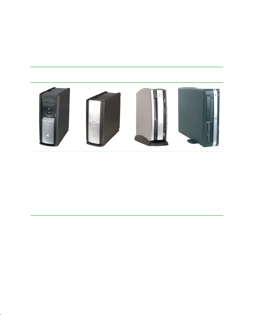
Identifying your computer case style
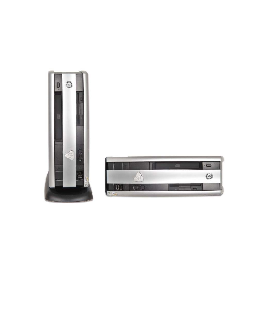
Use the following descriptions to identify your computer case style.
Gateway Tower Gateway Mid Tower Gateway Micro Tower Gateway New Micro
Tow er
The Gat eway Tower
does not have an
access door on the
front.
For inf ormation on the
Gateway Tower case,
see “Gateway Tower
Front” on page 3.
2
The Gateway Mid
Tower case has an
access door on the
front that covers the
drive bays and other
components.
For inf ormation on the
Gateway Mid Tower
case, see “Gateway
Mid Tower Front” on
page 8.
www.gateway.com
The Gateway Micro
Tower can be set
vertically into its
removable base, or
set horizontally on its
rubber feet.
For inf ormation on the
Gateway Micro Tower
case, see “Gateway
New Micro Tower
Front” on page 19.
The Gateway New
Micro Tower has a
rotating base and
does not have an
access door.
For inf ormation on the
Gatewa y Mi cro Tow er
case, see “Gateway
New Micro Tower
Front” on page 19.
Page 13
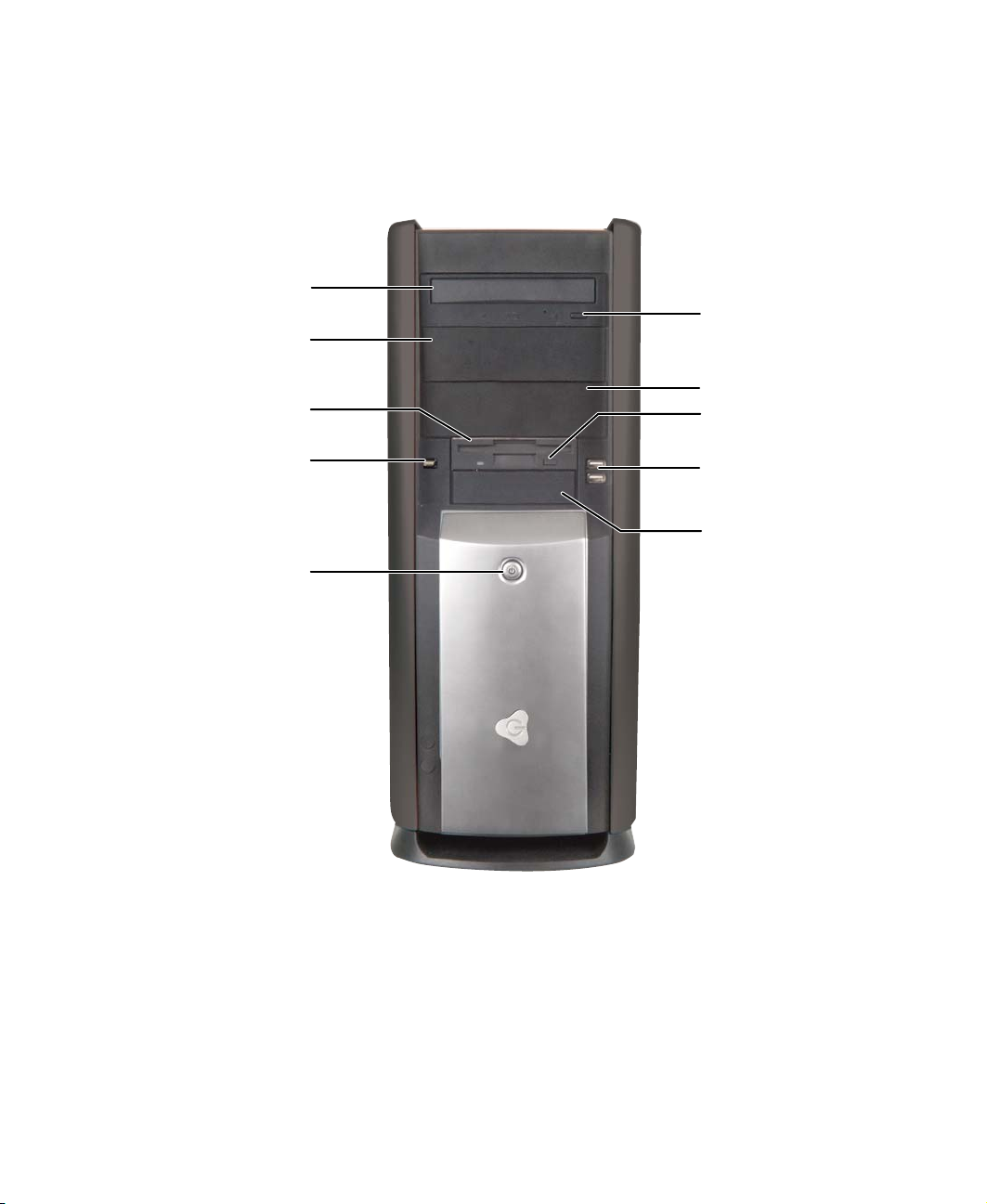
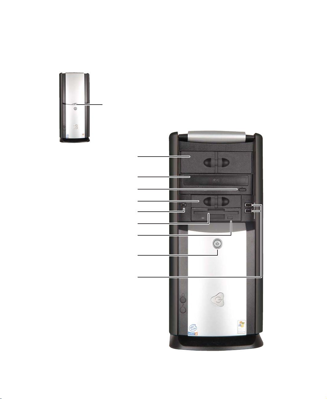
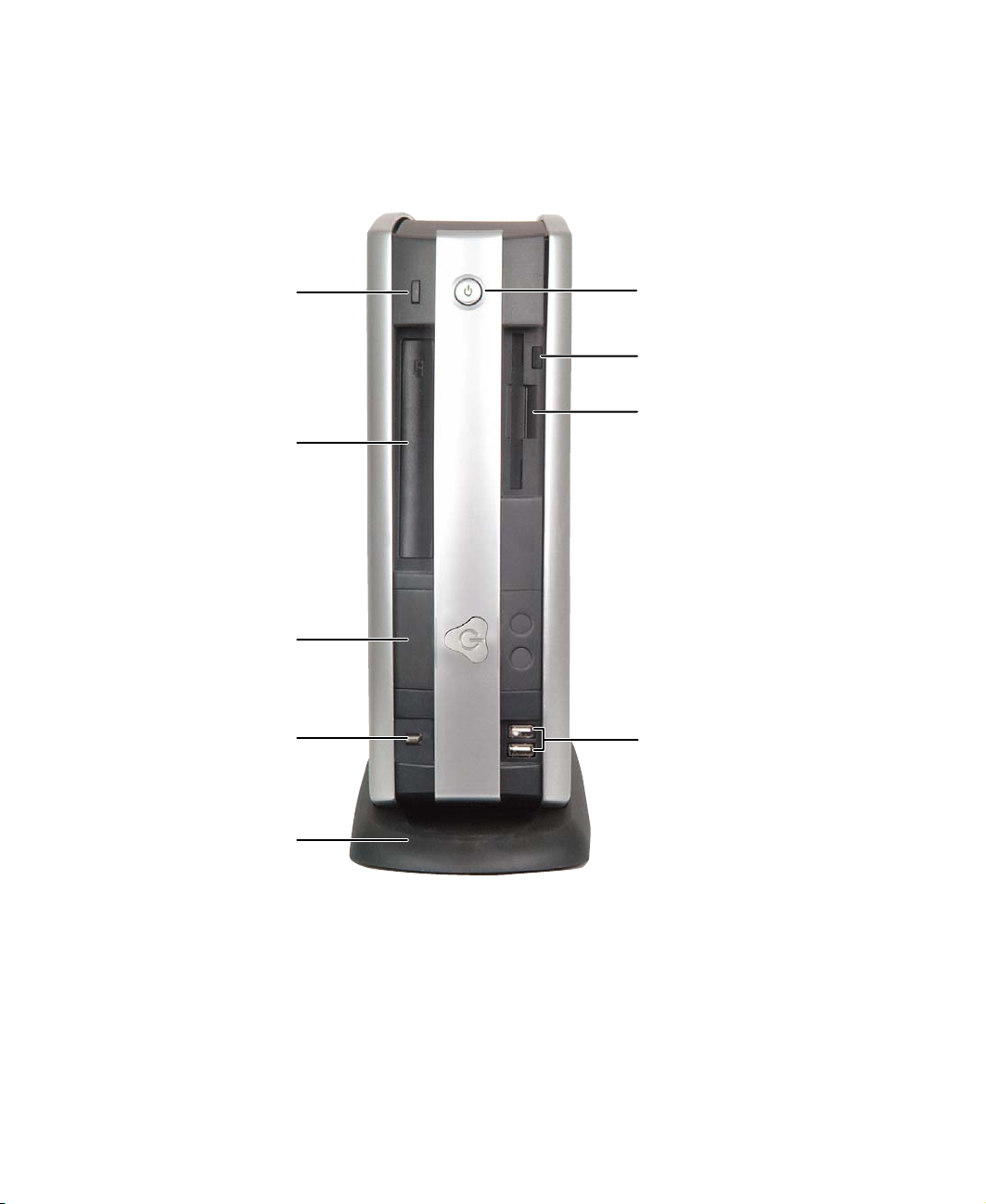
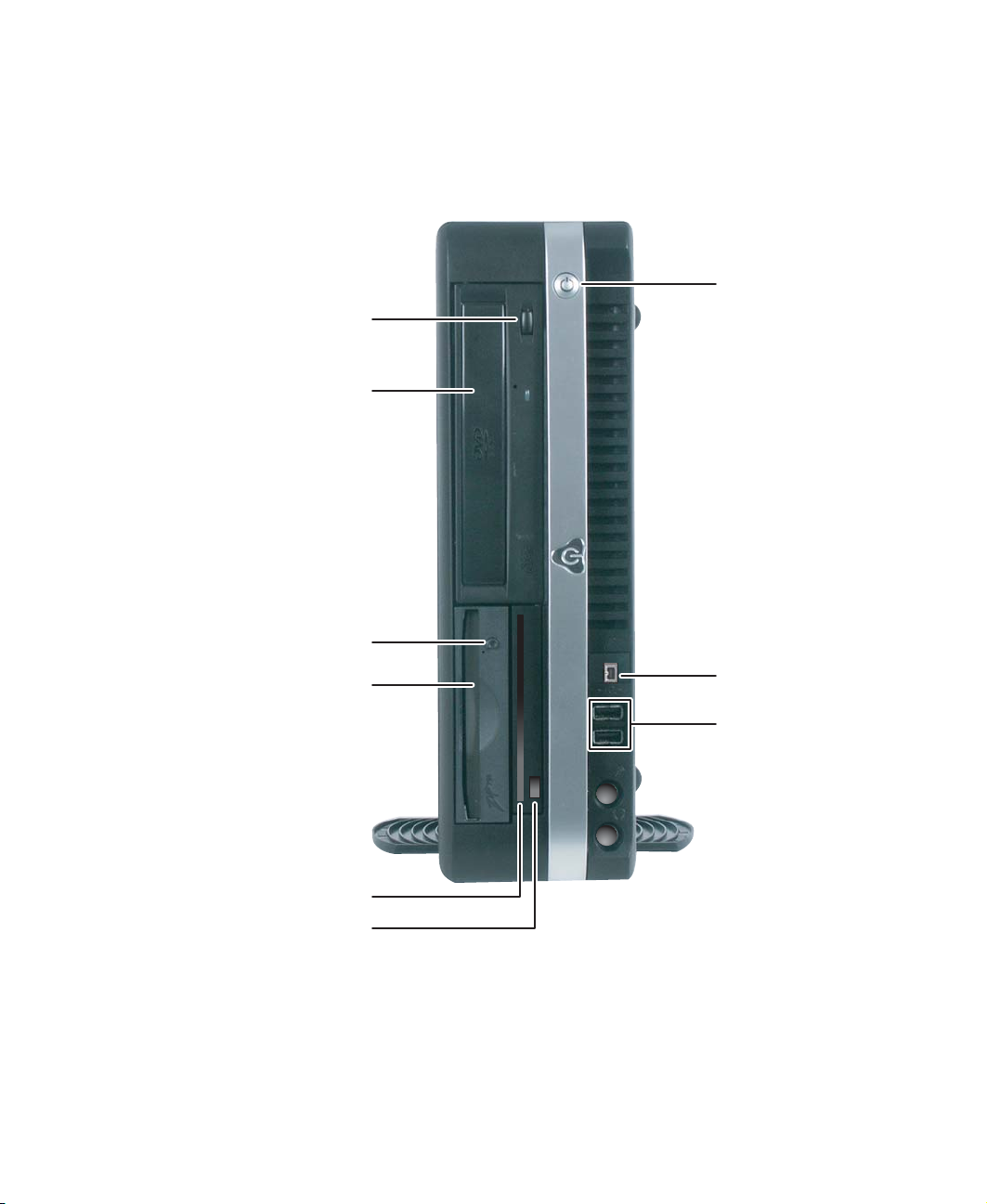
Gatewa y T ower Fr ont
Your computer may contain any of the following components.
CD/DVD/recordable drive
5.25-inch drive bay cover
Diskette drive (optional)
Gateway Tower Front
CD/DVD eject button
5.25-inch drive bay cover
Diskette eject button
IEEE 1394 port (optional)
Power button
USB ports
3.5-inch drive bay cover
www.gateway.com
3
Page 14

Chapter 1: Checking Out Yo ur Gateway Computer
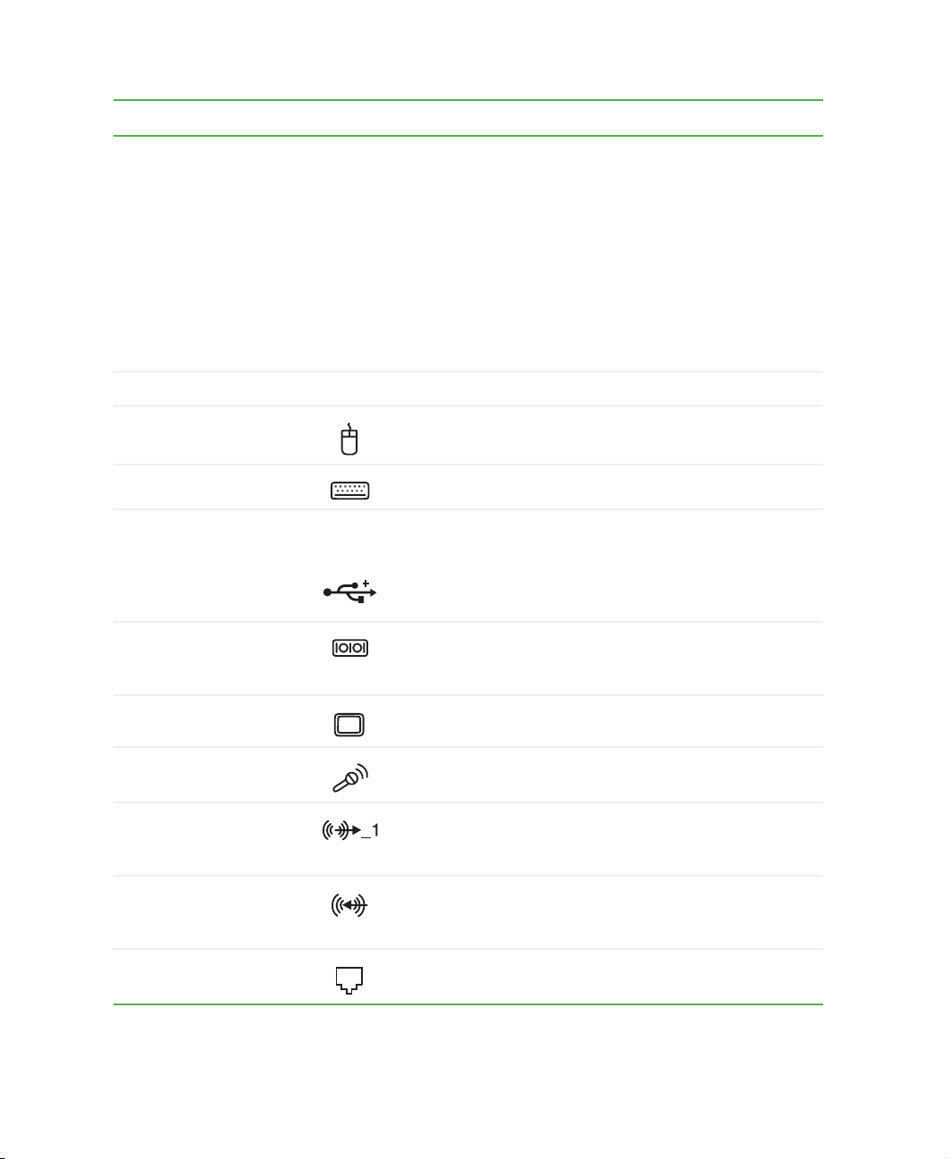
Component Icon Description
CD/DVD/recordable
drive
5.25-inch drive bay
cover
Diskette dri ve
(optional)
IEEE 1394 port
(optional)
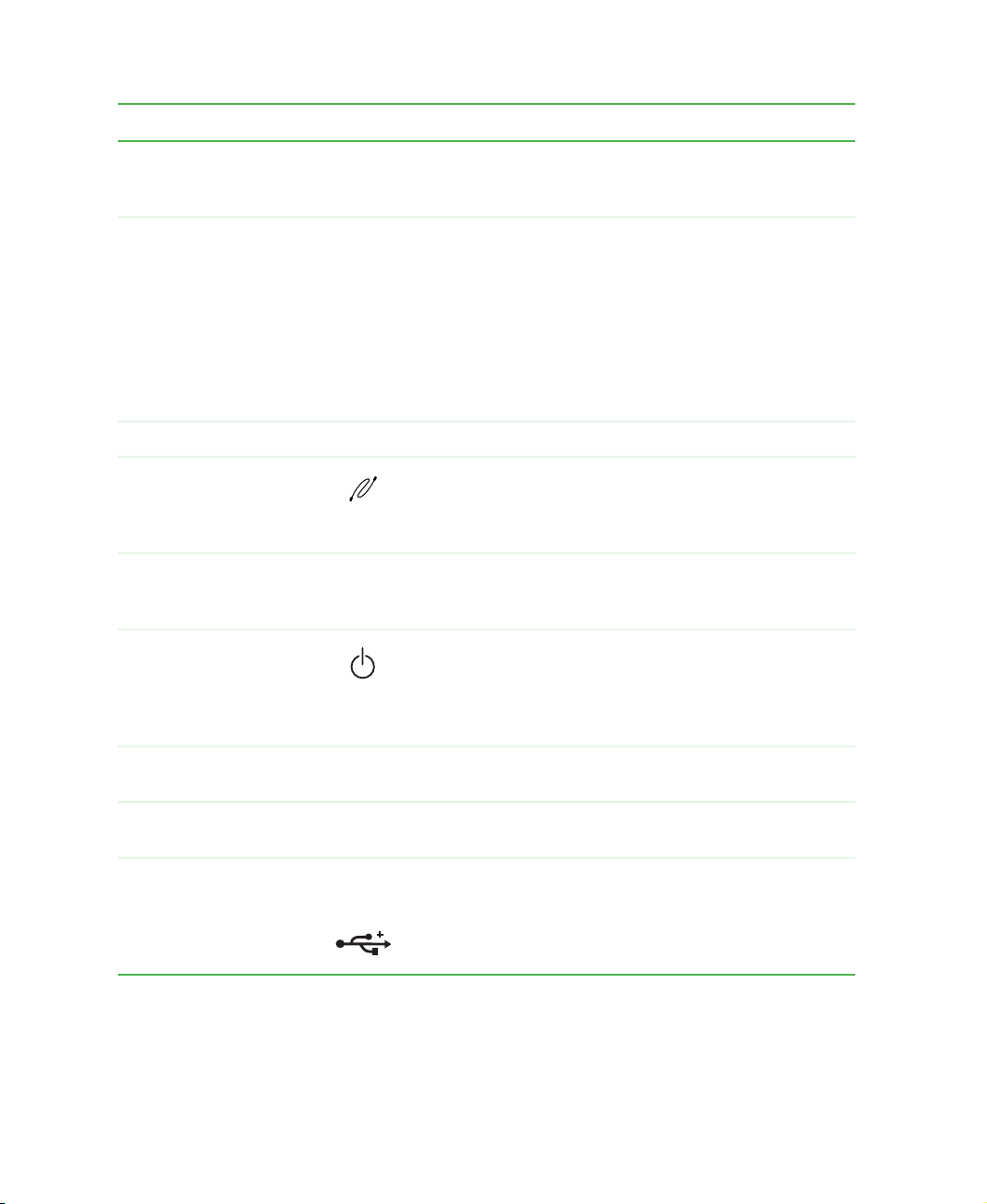
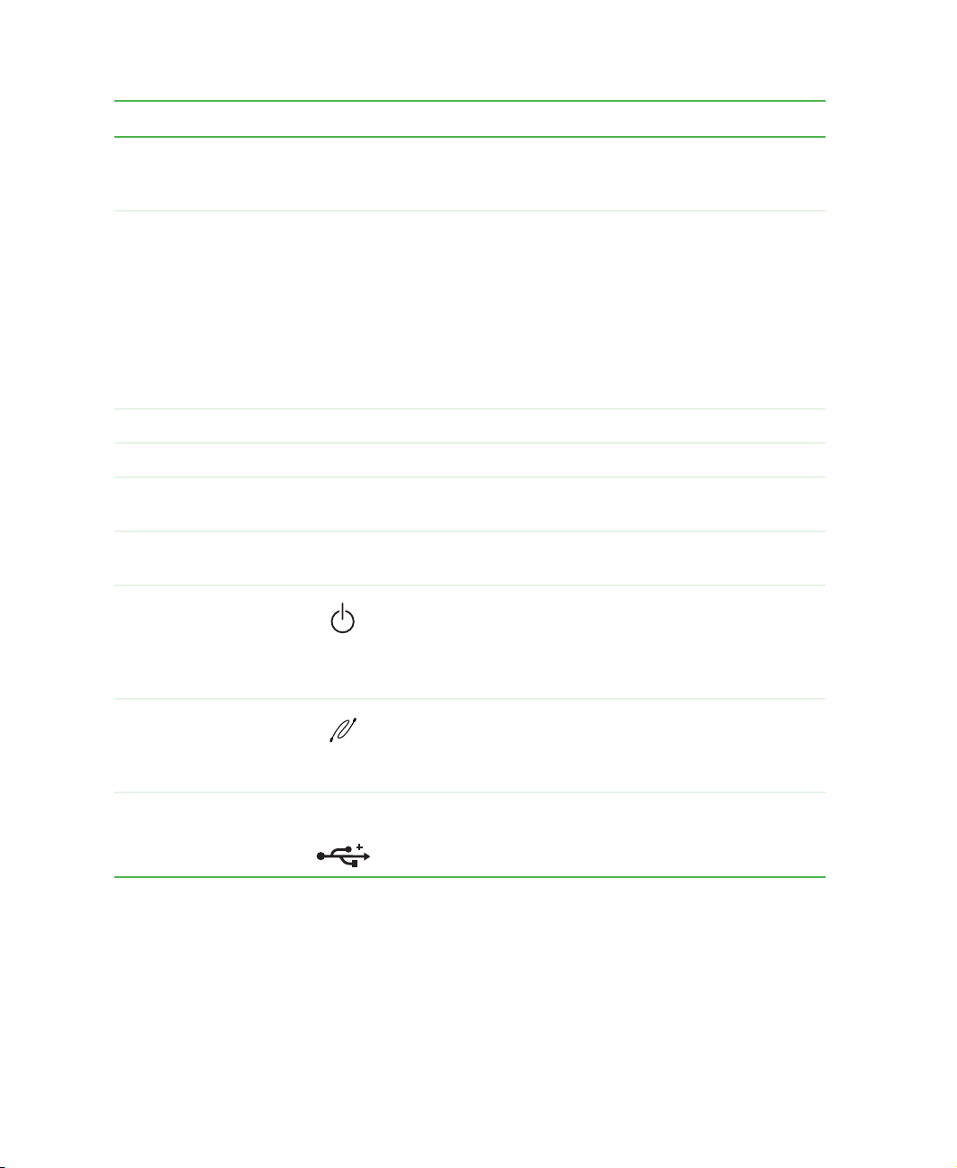
Power button Press this button to turn the power on or off. You can also
CD/DVD eject button Press this button to open the CD or DVD drive tray.
Diskette eject button Press this button to eject an inserted diskette.
Use this drive to listen to audio CDs, install games and
programs, watch DVDs, and store large files onto recordable
CDs and DVDs (depending on drive type). For more
information , see “U sing the CD o r DVD drive” on page 95.
This drive may be a CD, CD-RW, DVD/CD-RW, DVD,
DVD+RW, or DVD-RAM/-RW/CD-RW drive. To identify your
drive type and for more information about your drive, see
“Identifying drive types” on page 95.
Remove this cover to install an additional 5.25-inch drive.
Use this drive to store smaller files on diskettes. For more
information , see “U sing the dis kette dri ve” on page 93.
®
Plug an IEE E 1394 (also known as F irewire
device (such as a digital video camera) into this 4-pin
IEEE 1394 port.
configure the power button to operate in Standby/Resume
mode or Hibernate mode. For more information on changing
the power button setting, see “Setting up an uninterruptible
power supply” on page 165.
or i.Link®)
USB ports USB 2.0 Plug USB (Universal Serial Bus) devices (such as a digital
camera) into these por ts.
3.5-inch drive bay
cover
4
Remove this cover to install an additional 3.5-inch drive.
www.gateway.com
Page 15
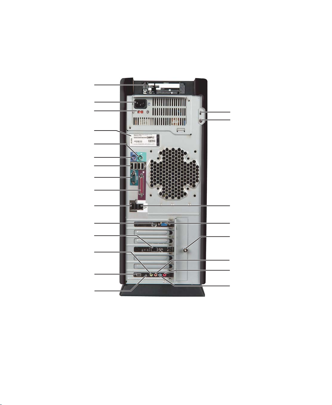
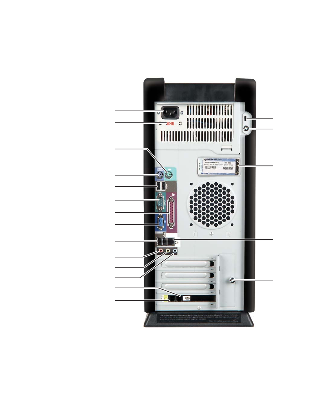
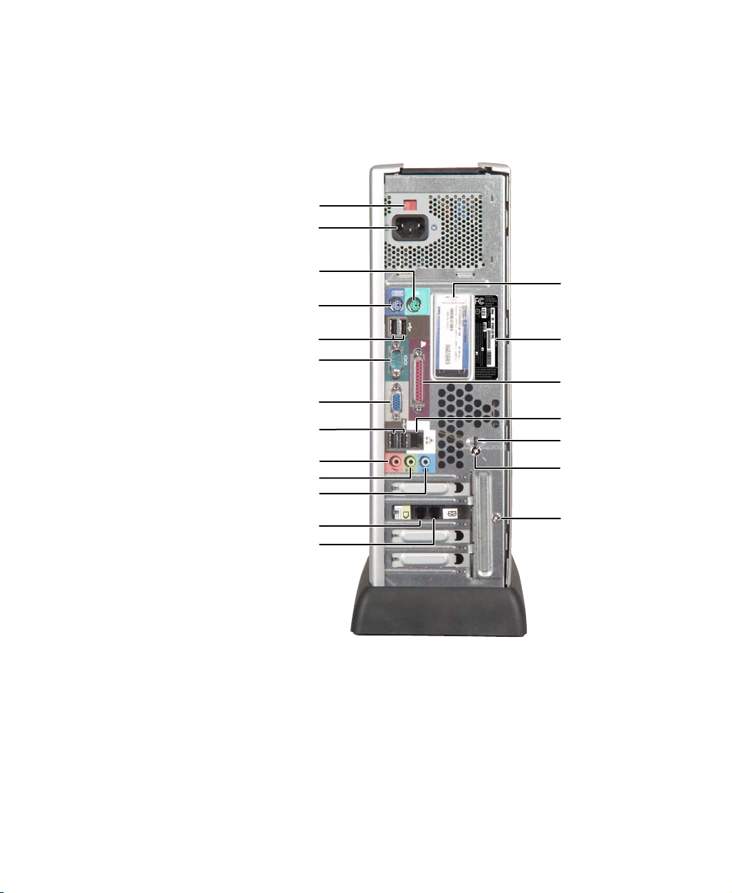
Gatewa y T ower Bac k
Your computer may contain any of the following components.
Product label
Power connector
Voltage switch
Microsoft Cer tificat e
of Authenticity
PS/2 mouse port
PS/2 keyboard por t
USB ports
Serial port
Para l le l p ort
Gateway Tow er Back
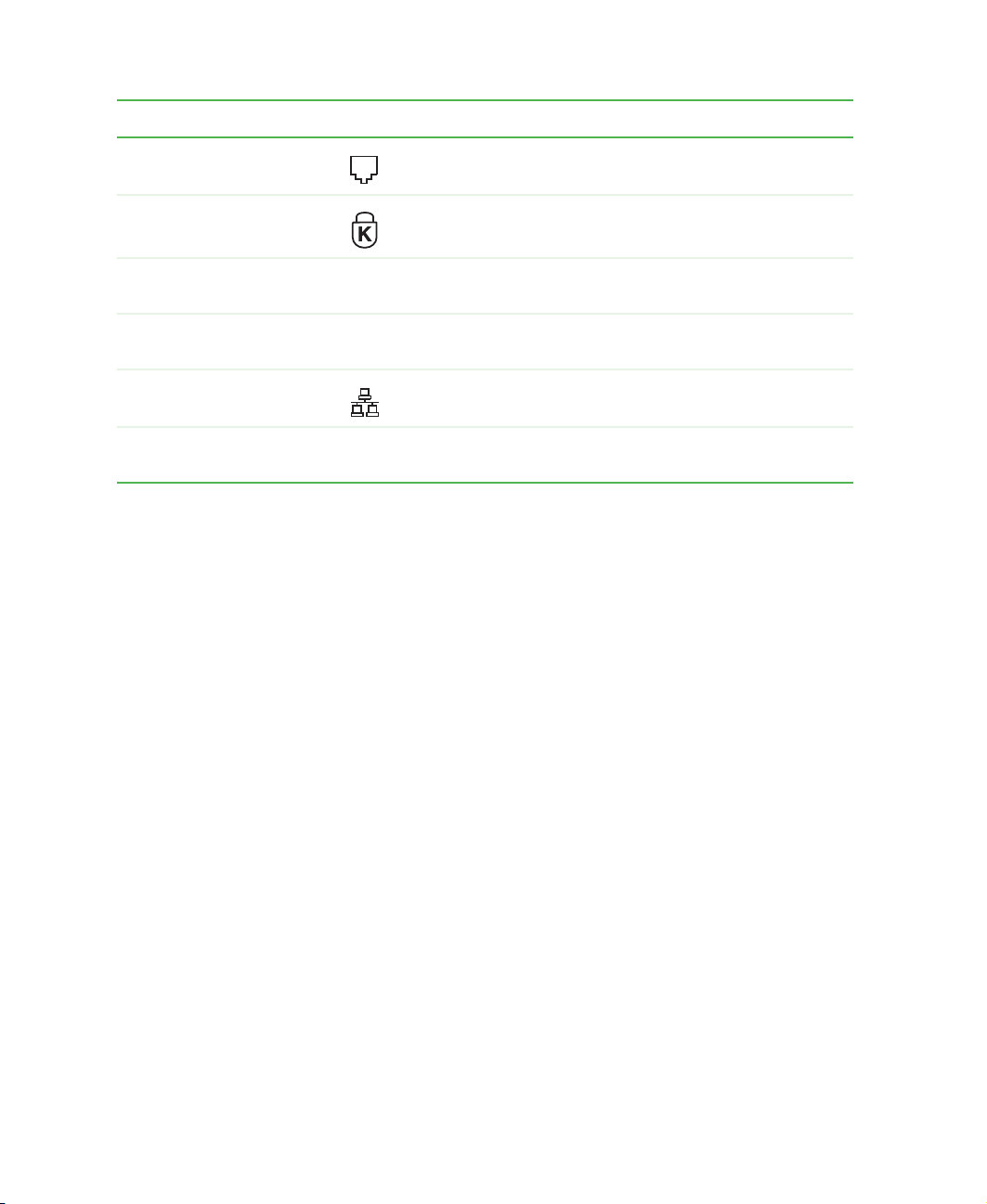
Kensington lock slot
Case cover
shipping scr ew
USB ports
TV jack
Modem jack
(optional)
Headphone/analog
speakers (Line out 1) jack
(optional)
IEEE 1394 port
(optional)
Rear out
(Line out 2) jack
(optional)
www.gateway.com
Ethernet
(network) jack
Monitor port
Add-in card retention
thumbscrew
Microphone jac k (optional)
Digital speakers (Digital out)
jack (optional)
Audio input (Line in) jack
(optional)
5
Page 16
Chapter 1: Checking Out Yo ur Gateway Computer
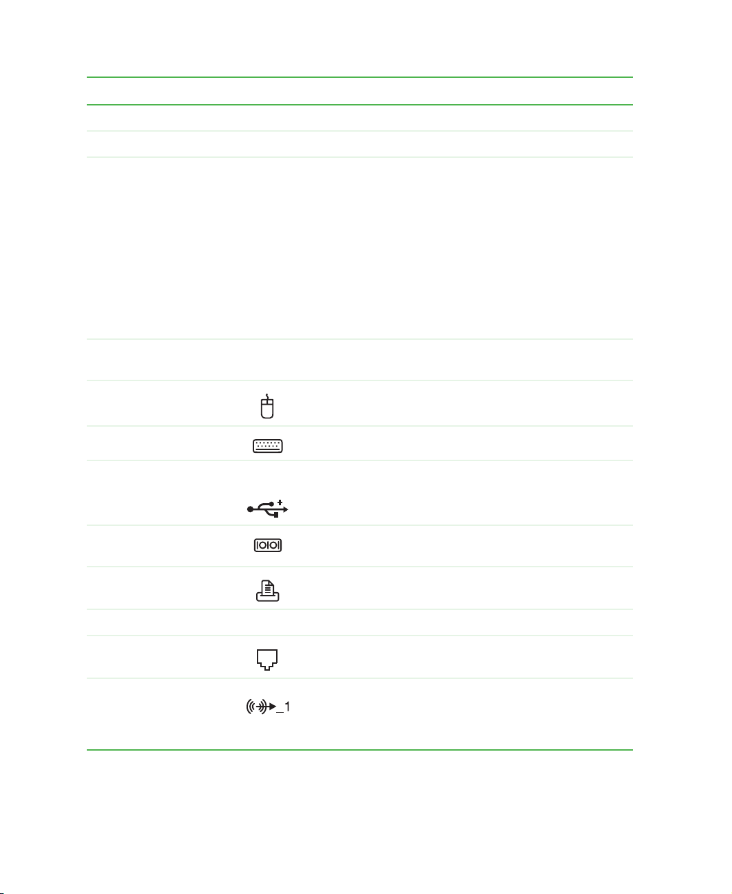
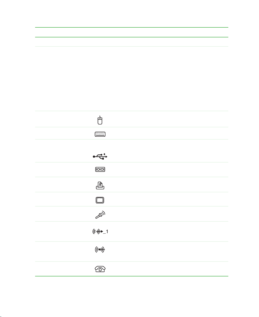
Component Icon Description
Product label Your computer’s serial and model number.
Power connector Plug the power cable into this connector.
Voltage switch Before turning on your computer, make sure that this
switch is in th e correct po sition f or the co rrect v oltage . The
switch is prese t at th e factor y wit h the correc t voltage for
your area.
In the United States, the utility power is supplied at a
nominal 115 volts at 60 Hz. The power supply should
always be set to this when your computer is operating in
the United States. In other areas of the world, such as
Europe, the utility power is supplied at 230 volts at 50 Hz.
If your computer is operating in an environment such as
this, the voltage switch should be moved to 230.
Microsoft Certificate of
Authenticity
PS/2 mouse port Plug a Personal System/2
PS/2 keyboard por t Plug a PS/2 keyboard into this port.
USB ports USB 2.0 Plug USB (Universal Serial Bus) devices (such as a
Serial port Plug a serial device (such as a digital camera) into this
Parallel por t Plug a parallel device (such as a printer) into this por t.
TV jack Plug a television into this port.
Modem jack
(optional)
Headphone/analog
speakers (Line out 1)
jack
(optional)
The Microsoft Certificate of Authenticity (COA) contains
your Windows p roduct key.
®
(PS/2) mouse into this por t.
mouse, keyboard, or printer) into these ports.
port.
Plug a modem c able into th is jack.
Plug powered, analog front speakers, an external
amplifier, or headphones into this jack. This jack is
color-coded green.
6
www.gateway.com
Page 17
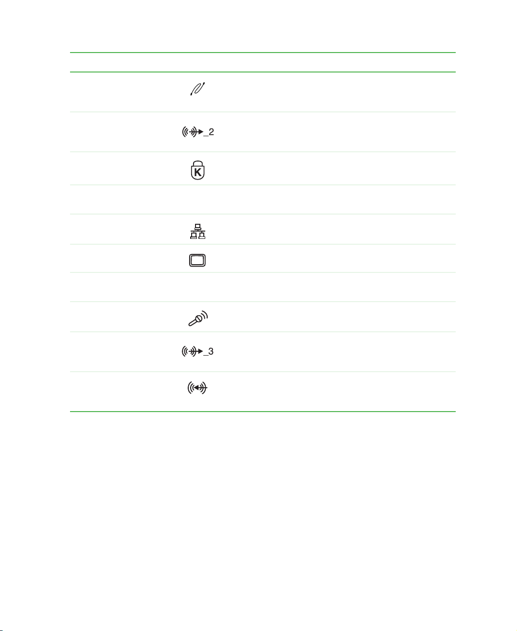
Component Icon Description
Gateway Tow er Back
IEEE 1394 port
(optional)
Rear out (Line out 2)
jack
(optional)
Kensington™ lock slot Secure your computer to an object by connecting a
Case cover shipping
screw
Ethernet (network) jack Plug a 10/100 Ethernet network cable or a device (such
Monitor port Plug a monitor into this port.
Add-in card retention
thumbscrew
Microphone jack
(optional)
Digital speakers
(Digital ou t) jack
(optional)
Plug an IEEE 1394 (also known as Firewire or i.Link)
device (such as a scanner or hard drive) into this 6-pin
IEEE 1394 port.
Plug powered, analog rear speakers or an external
amplifier into this jack. This jack is color-coded black.
Kensington cable lock to this slot.
Remove this screw be fore opening t he case.
as a DSL or cable modem) into this jack.
Remove th is scre w when addi ng or replac ing add-i n cards .
Plug a microphone into this jack. This jack is color-coded
red or pink.
Plug digital speakers into this jack. You can also use this
jack for an analog center speaker or analog subwoofer.
This jack is color-coded orange.
Audio input (Line in)
jack
(optional)
Plug an external audi o input source (such as a stere o) into
this jack so you can record sound on your computer. This
jack is color-coded blue.
www.gateway.com
7
Page 18
Chapter 1: Checking Out Yo ur Gateway Computer
Gatewa y Mid T ower Fr ont
Your computer may contain any of the following components.
Access door
5.25-inch drive b ay cover
CD/DVD/R ecordable drive
CD/DVD eject button
3.5-inch drive bay cover
IEEE 1394 port (optional)
Diskette dri ve (optiona l)
Diskette ej ect button
Pow er b u tt o n
USB ports
8
www.gateway.com
Page 19

Gateway Mid Tower Front
Component Icon Description
Access door Open this door to acce ss y our driv es and othe r comp onents.
5.25-inch drive bay
cover
CD/DVD/Recordable
drive
CD/D VD eject bu tton Press this button to open the CD or DVD drive tra y. For more
3.5-inch drive bay
cover
IEEE 1394 port
(optional)
Diskette dri ve
(optional)
Diskette eject button Press this button to eject an inserted diskette. For more
Power button Press this button to tur n the power on or off. You can also
Remove this cover to install an additional 5.25-inch drive.
Use this drive to listen to audio CDs, install games and
programs, w atch D VDs, and store large files onto recordable
CDs and DVDs (depending on drive type). For more
information, see “Using the CD or DVD dr ive” on page 95.
This dri ve may be a CD, CD-RW, DVD/CD-RW, DVD,
DVD+RW, or DVD-RAM/-RW/CD-RW drive. To identify your
drive type and for more information about your dr ive, see
“Identifying drive types” on page 95.
information, see “Using the CD or DVD dr ive” on page 95.
Remove this cover to install an additional 3.5-inch drive.
Plug an IEEE 1394 (also known as Firewire® or i.Link®)
device (such as a digital video came ra) into t his 4-pin
IEEE 1394 port.
Use this drive to store smaller files on diskettes. For more
information, see “Using the diskette drive” on page 93.
information, see “Using the diskette drive” on page 93.
configure the power button to operate in Standby/Resume
mode or Hibernate m ode. F or more information on changi ng
the power button setting, see “Changing power settings” on
page 160.
USB ports USB v2.0 Plug USB (Universal Serial Bus) devices (such as a digital
camera) into these por ts.
www.gateway.com
9
Page 20
Chapter 1: Checking Out Yo ur Gateway Computer
Gatewa y Mid T ower Bac k
Your computer may contain any of the following components.
Power connector
Voltage switch
PS/2 mouse port
PS/2 keyboard por t
USB ports
Serial port
Para l le l p ort
Monitor port
USB ports
Microphone jack
Headphone/speakers (Line out) jack
Audio input (Line in) jack
Telephone jack (optional)
Kensington
lock slot
Case cover
shipping
screw
Microsoft
Certificate of
Authenticity
Ethernet
(Network)
jack
Add-in card
retention
thumbscrew
Modem jack (optional)
10
www.gateway.com
Page 21
Gateway Mid Tower Back
Component Icon Description
Power connector Plug the power cable into this connector.
Voltage switch Before turning on your computer, make sure that this
switch is in the correct position f or the correct voltage. Th e
switch is preset at the factory with the correct voltage for
your area.
In the United States, the utility power is supplied at a
nominal 115 volts at 60 Hz. The power supply should
always be set to this when your computer is operating in
the United States. In other areas of the world, such as
Europe, the uti lity p ower is suppl ied at 230 v olts a t 50 Hz .
If your computer is operating in an environment such as
this, the voltage switch should be moved to 230.
®
PS/2 mouse port Plug a Personal System/2
PS/2 keyboard por t Plug a PS/2 keyboard into this port.
USB ports USB v2.0 Plug USB (Universal Serial Bus) devices (such as a
mouse, keyboard, or printer) into these ports.
(PS/2) mous e into th is por t.
Serial port Plug a serial device (such as a digital camera) into this
port.
Parallel por t Plug a parallel device (such as a printer) into this port.
Monitor port Plug a monitor into this port.
Microphone jack Plug a microphone into thi s jac k . This j ac k is col or-code d
red or pink.
Headphone/speakers
(Line out) jack
Audio input (Line in)
jack
Telephone jack
(optional)
Plug powered, analog front speakers, an external
amplifier, or head phones in to this jack. This jack is
color-coded green.
Plug an exter nal audio input source (such as a stereo)
into this jack so you can record sound on your com pu ter.
This jack is color-coded blue.
If your modem has a telephone jack, plug the cable for
a telephone into this jack.
www.gateway.com
11
Page 22
Chapter 1: Checking Out Yo ur Gateway Computer
Component Icon Description
Modem jack (optional) Plug a modem cable into this jack.
Kensington™ lock slot Secure your computer to an object by connecting a
Kensington cable lock to this slot.
Case cover shipping
screw
Microsoft Certificate of
Authenticity
Ethernet (Network) jack Plug an Ethernet network cable or a device (such as a
Add-in card retention
thumbscrew
Remove this screw before opening the case.
The Microsoft Certificate of Authenticity (COA) contains
your Windows product key.
DSL or cable modem) into this jack.
Remove this screw when adding or replacing add-in
cards.
12
www.gateway.com
Page 23
Gateway Micro Tower Front
Gatewa y Micro T o wer Front
Your computer may contain any of the following components.
CD/DVD eject
button
CD/DVD/Recordable
drive
Cover release
handle
IEEE 1394 port
(optional)
Power button
Diskette eject
button
Diskette drive
(optional)
USB ports
Removable base
www.gateway.com
13
Page 24
Chapter 1: Checking Out Yo ur Gateway Computer
Component Icon Description
CD/DVD eject button Press this button to open the CD or DVD drive tray. For
more information, see “Using the CD or DVD drive” on
page 95.
CD/DVD/Recordable
drive
Cover release handle Press this handle to open the computer cover.
IEEE 1394 port (optional) Plug an IEEE 1394 (also known as Firewire
Removable base Install this base when using your computer ver tically.
Power button Press this button to turn the power on or off. You can also
Diskette eject button Press this button to eject an inserted diskette. For more
Use this drive to listen to audio CDs, install games and
programs, watch DVDs, and store large files onto
recordable CDs and DVDs (depending on drive type). For
more information, see “Using the CD or DVD drive” on
page 95.
This drive may be a CD, CD-RW, DVD/CD-RW, DVD,
D VD+RW, or D VD-RAM/-RW/CD-R W drive . To identify your
drive type and for more information about your drive, see
“Identifying drive types” on page 95.
®
or i.Link®)
device (such as a digital video camera) into this 4-pin
IEEE 1394 port. For more information, see “Installing a
printer, scanner, or other peripheral device” on page 44.
Remove this base when using your computer horizontally
or when accessing components inside the case.
configure the power button to operate in Standby/Resume
mode or Hibernate mode. For more information on
changing the power button setting, see “Power
management” on page 159.
information, see “Using the diskette drive” on page 93.
Diskette dr ive (o pti ona l) Use thi s dr ive to sto re sm alle r f iles on d iskett es. For mor e
information, see “Using the diskette drive” on page 93.
USB ports USB
2.0
14
Plug USB (Universal Serial Bus) devices (such as a USB
Iomega™ Zip™ drive, printer, scanner, camera, keyboard,
or mouse) into these por ts. For more information, see
“Installing a printer, scanner, or oth er peripheral device” on
page 44.
www.gateway.com
Page 25
Gatewa y Micro T o wer Back
Your computer may contain any of the following components.
Voltage switch
Power connector
Gateway Micro Tower Back
PS/2 mouse port
PS/2 keyboard por t
USB ports
Serial port
Monitor port
USB ports
Microphone jack
Headphone/analog speakers (Line out) jack
Audio input (Line in) jack
Modem jack
Telephone jack
(optional)
Microsoft
Certificate of
Authenticity
System
label
Parallel
port
Ethernet
(network) jack
Kensing ton lock slot
Case cover
shipping screw
Add-in card
retention
thumbscrew
www.gateway.com
15
Page 26
Chapter 1: Checking Out Yo ur Gateway Computer
Component Icon Description
V oltage switch Before turning on your computer , m ake su re that this s witch
is in the correct po sition f or the corre ct powe r av ailabl e. The
switch is prese t at the factor y wit h the corre ct voltage for
your area.
In the United States, the utility power is supplied at a
nominal 115 volts at 60 Hz. The power supply should
always be set to this when your computer is operating in
the United States. In other areas of the world, such as
Europe, the utility power is supplied at 230 volts at 50 Hz.
If your computer is operating in an environment such as
this, the voltage switch should be moved to 230.
Power connector Plug t he power cable i nto this co nnector.
PS/2 mouse port Plug a Personal System/2
PS/2 keyboard por t Plug a PS/2 keyboard into this port.
®
(PS/2) mous e into th is por t.
USB ports USB
2.0
Serial port Plug a serial de vice (su ch as a d igital camer a) into t his port.
Monitor port Plug a monitor into this por t.
Microphone jack Plug a microphone into this jack. This jack is color-coded
Headphone/analog
speakers (Line out) jack
Audio input (Line in) jack Plug an external audio input sour ce (su ch as a ste r eo ) int o
Modem jack Plug a modem cable into this jack.
Plug USB (Universal Serial Bus) devices (such as a USB
Iomega™ Zip™ drive, printer, scanner, camera, keyboard,
or mouse) into these por ts. For more information, see
“Installing a printer, scanner, or oth er peripheral device” on
page 44.
For more information, see “Installing a printer, scanner, or
other peripheral device” on page 44.
red or pink.
Plug powered, an alog front spea kers , an e xternal amplifi er ,
or headphones into this jack. This jack is color-coded lime
green.
this jack so you can record sound on your computer. This
jack is color-coded blue.
16
www.gateway.com
Page 27

Gateway Micro Tower Back
Component Icon Description
Telephone jack (optional) If your modem has a telephone jack, plug the cable for a
telephone into this jack.
Microsoft Certificate of
Authenticity
System label Includes your computer’s model and serial number. For
Parallel port Plug a parallel device (such as a printer) into this port. For
Ethernet (network) jack Plug a 10/100 Ethe rnet netwo rk cable or a device (such as
Kensington™ lock slot Secure your computer to an object by connecting a
Case cover shipping
screw
Add-in card retention
thumbscrew
Contains yo ur W in do ws p r odu ct key . For more information,
see “Microsoft Certificate of Authenticity” on page 26.
more information, see “Identifying your model” on page 25.
more informatio n, see “Installing a printer , scanner, or other
peripheral device” on p age 44.
a DSL or cable modem for a broadband Internet
connection) into this jack. For more information, see
“Learning about the Internet” on page 80.
Kensington cable lo ck to this sl ot.
Remove this screw before opening the case.
Remove this screw when adding or replacing add-in cards.
www.gateway.com
17
Page 28
Chapter 1: Checking Out Yo ur Gateway Computer
Desktop to to wer con version
You can convert your Gateway Micro Tower case from desktop to tower
configuration using the accessory base included with your system. For more
information, see “Upgrading the Gateway Micro Tower Case” on page 243.
18
www.gateway.com
Page 29
Gateway New Micro Tower Front
Gatewa y New Micro Tower Fr ont
Your computer may contain any of the following components.
Power button
CD/DVD eject button
CD/DVD/Recordable dr ive
Zip drive eject button
Zip drive
Diskette drive (optional)
Diskette eject button
www.gateway.com
IEEE 1394 port
(optional)
USB ports
19
Page 30
Chapter 1: Checking Out Yo ur Gateway Computer
Component Icon Description
CD/DVD eject button Press this button to open the CD or DVD drive tray. For
more information, see “Using the CD or DVD dr ive” on
page 95.
CD/DVD/Recordable
drive
Zip drive eject button Press this button to eject an inserted Zip disk.
Zip drive Use this drive to store larger files on Zip disks.
Diskette dr ive
(optional)
Diskette eject button Press this button to eject an inserted diskette. For more
Power button Press this button to turn the power on or off. You can also
IEEE 1394 port
(optional)
Use this drive to listen to audio CDs, install games and
programs, watch DVDs, and store large files onto
recordable CDs and DVDs (depending on drive type). For
more information, see “Using the CD or DVD dr ive” on
page 95.
This drive may be a CD, CD-RW, DVD/CD-RW, DVD,
DVD+RW, or DVD-RAM/-RW/CD-RW drive. To identify
your drive type and for more information about your drive,
see “Identifying drive types” on page 95.
Use this drive to store smaller files on diskettes. For more
information, see “Using the diskette drive” on page 93.
information, see “Using the diskette drive” on page 93.
configure the pow er b utt on to op erate in Stand by /Resum e
mode or Hibernate mode. For more information on
changing the power button setting, see “Power
management” on page159.
®
Plug an IEEE 1394 (also known as Firewire
device (such as a digital video camera) into this 4-pin
IEEE 1394 port. For more information, see “Installing a
printer, scanner, or other peripheral device” on page 44.
or i.Link®)
USB ports USB v2.0 Plug USB (Universal Serial Bus) devices (such as a digital
camera) into these por ts.
20
www.gateway.com
Page 31

Gateway New Micro Tower Back
Gatewa y New Micro Tower Bac k
Your computer may contain any of the following components.
PS/2 keyboard por t
USB ports
Serial port
Monitor port
USB ports
Microphone jack
PS/2 mouse port
Kensington
lock slot
Case cover
shipping screw
Parallel por t
Ethernet
(Network) jack
Audio input
(Line in) jack
Headphone/speakers
(Line out) jack
Power connector
www.gateway.com
Voltage switch
21
Page 32

Chapter 1: Checking Out Yo ur Gateway Computer
Component Icon Description
PS/2 keyboard por t Plug a PS/2 keyboard into this port.
USB ports USB v2.0 Plug USB (Universal Serial Bus) device s (such as a
mouse, keyboard, or printer) into these ports.
Serial port Plug a serial device (such as a digital camera) into
this port.
Monitor po rt Plug a moni tor into t his por t.
Microphone jack Plug a microphone into this jack. This jack is
color-co ded red or pink.
Power connector Plug the p ower cable into this con nector.
PS/2 mouse port Plug a PS/2 mouse into this port.
Kensington™ lock slot Secure your computer to an object by connecting a
Kensington cable lo ck to this slo t.
Case cover shipping screw Remove this screw before opening the case.
Parall el port Plug a parallel device (such as a printer) into this port.
Ethernet (Network) jack Plug an Ethernet network cable or a device (such as
a DSL or cable modem) into this jack.
Audio input (Line in) jack Plug an external audio input source (such as a
stereo) into this jack s o you can record sound on your
computer. This jack is color-coded blue.
22
www.gateway.com
Page 33

Component Icon Description
Gateway New Micro Tower Back
Headphone/speakers
(Line out) jack
V olta ge switch Before turning on yo ur compute r, make sure that this
Plug powered, analog front speakers, an exter nal
amplifier, or headphones into this jack. This jack is
color-coded green.
switch is in the correct position f or the correc t voltage .
The switch is preset at the factory with the correct
voltage for your area.
In the United States, the utility power is supplied at
a nominal 115 volts at 60 Hz. The power supply
should always be set to this when your computer is
operating in the United States. In other areas of the
world, such as Europe, the utility power is supplied
at 230 volts at 50 Hz. If your computer is operating
in an environme nt such as this, the voltag e switch
should be moved to 230.
www.gateway.com
23
Page 34

Chapter 1: Checking Out Yo ur Gateway Computer
Desktop to to wer con version
You can convert your Gateway New Micro Tower case from desktop to tower
configuration using the rotating foot included with your system.
24
www.gateway.com
Page 35

Identifying your mo del
Identifying your model
Important The label s shown in thi s sectio n are for inform ational
purposes only. Label inf ormation va ries by mo del, f eatures
ordered, and location.
Gateway model number
The label on the back of your computer case contains information that
identifies your computer model. The label also contains your serial number.
Gateway Technical Support will need this information if you call for assistance.
Gateway serial number
You can locate the Gateway serial number:
■ Printed on a white sticker on the front or top of your computer case.
■ Printed on the customer invoice that came with your computer. The
invoice also contains your customer ID number.
■ Displayed in HelpSpot in Windows XP. Click Start, Help and Suppor t, then
click
View product serial number.
www.gateway.com
25
Page 36

Chapter 1: Checking Out Yo ur Gateway Computer
Microsoft Certificate of Authenticity
The Microsoft Certificate of Authenticity label found on the back or side of your
computer case includes the product key code for your operating system.
26
www.gateway.com
Page 37

Finding your sp ecifications
Finding your specifications
For more information about your computer, such as memory size, memory type,
and hard drive size, go to the
eSupport page at support.gateway.com
additional Gateway documentation and detailed specifications.
In Windows XP, view your computer’s serial number or check your
specifications by clicking
My Computer Info link in HelpSpot or visit Gateway’s
. The eSupport page also has links to
Start, Help and Support, then clicking My Computer Info.
www.gateway.com
27
Page 38

Chapter 1: Checking Out Yo ur Gateway Computer
You can also find out more about your computer at the Gateway eSupport site.
Visit support.gateway.com
page 53.
. For more information, see “Using eSupport” on
28
www.gateway.com
Page 39

Accessories
Gateway offers various accessories that can help you make the most of using
your computer. To order accessories, visit the Accessory Superstore at
accessories.g
Networking kit
With a networking kit, you can network (link) two or more computers. After
you have set up a network, you can access the files, drives, and printers on
linked computers, play multiplayer games, and even share one Internet
connection.
Two types of networking kits are available. Wireless networking kits use radio
frequency to link your computers wirelessly. Ethernet networking kits use
network cabling to link your computers.
Imaging equipment
A digital camera lets you take pictures that you can view and edit on your
computer.
A digital video camera lets you take videos and pictures that you can view and
edit on your computer.
ateway.com.
Accessories
A scanner copies an image, such as a graphic or document, then stores the copy
in a file.
You can attach your digital photographs or scanned images to e-mail messages
or post them on a Web site.
Printers
You can attach almost any type of printer to your computer. The most common
types are inkjet and laser printers, which print in color or in black and white.
Inkjet printers and cartridges are relatively inexpensive, but they are slower than
laser printers. Using an inkjet color printer, you can print pictures, banners,
and greeting cards, as well as documents.
Laser printers and cartridges are more expensive, but they usually print much
faster than inkjet printers. Laser printers are better than inkjet printers when
you are printing large documents.
www.gateway.com
29
Page 40

Chapter 1: Checking Out Yo ur Gateway Computer
Storage Devices
If you need additional storage space or you want to back up your files, you
can add storage devices to you computer.
With a recordable CD or DVD drive, you can free up hard drive sp ace by backing
up files, then removing them from your hard drive. Writable CDs can hold as
much as 700 MB of data. Writable DVDs can hold as much as 4.7 GB of data.
For more information about using recordable drives, see “Creating CDs and
DVDs” on page 115.
Iomega Zip drives, like diskette drives, use disks to store data. Zip disks can store
100 MB, 250 MB, or 750 MB of data. You can use a Zip drive to back up files
you do not use so you can remove them from your hard drive. Zip drives also
provide an easy way to transfer files between computers (if both computers have
internal Zip drives or if you have one external, portable Zip drive).
If you need to back up your entire system, you probably need a tape backup
(TBU) drive. TBU drives, like tape recorders, use magnetic tape cartridges to store
data. Tape drive cartridges can store 2 GB, 20 GB, 40 GB, 130 GB, or more of
data.
If you want to increase your internal storage space, try adding a second hard
drive or replacing your existing hard drive with a larger drive. For more
information about installing a larger drive, see “Adding or replacing a hard
drive” on page 229 or “Replacing the hard drive” on page 272.
Memory
Large programs, such as multimedia games or graphics programs, use a lot of
memory. If your programs are running more slowly than you think they should,
try adding more memory. For more information, see “Installing memory” on
page 283.
Uninterruptible power suppl ies
A standby, uninterruptible power supply (UPS) protects your computer from
data loss during a total power failure. A UPS uses a battery to keep your
computer running temporarily during a power failure so you can save your work
and shut down your computer correctly. A UPS may also provide protection
from power surges. For information, see “Setting up an uninterruptible power
supply” on page 165.
30
www.gateway.com
Page 41

Setting Up Your
Computer
This chapter provides basic information about your
Gateway computer. Read this chapter to learn how to:
■ Use your computer safely
■ Start and turn off your computer
■ Restart (reboot) your computer
2
31
Page 42

Chapter 2: Setting Up Your Computer
Protecting fr om power source problems
During a power surge, the voltage level of electricity coming into your computer
can increase to far above normal levels and cause data loss or system damage.
Protect your computer and peripheral devices by connecting them to a surge
protector, which absorbs voltage surges and prevents them from reaching your
computer.
Warning High voltages can enter your computer through both the
power cord and the modem connection. Protect your
computer by using a surge protector. If you have a
telephone modem, use a surge protector that has a
modem jack. If you have a cable modem, use a surge
protector that has an antenna/cable TV jack. During an
electrical storm, unplug both the surge protector and the
modem.
An uninterruptible power supply (UPS) supplies battery power to your computer
during a power failure. Although you cannot run your computer for an
extended period of time with a UPS, a UPS lets you run your computer long
enough to save your work and shut down your computer normally. For more
information, see “Setting up an uninterruptible power supply” on page 165.
32
www.gateway.com
Page 43

W orking safel y
Before using your computer, read the following recommendations for setting
up a safe and comfortable work area and avoiding discomfort and strain.
Top of screen is not
higher than eye level
Screen is
perpendicular to
your line of sight
Hands and
arms are
parallel to
the floor
Working safely
Feet are flat on the floor
Reducing eye strain
Sunlight or bright indoor lighting should not reflect on the monitor screen or
shine directly into your eyes.
■ Position the computer desk and monitor so you can avoid glare on your
screen and light shining directly into your eyes. Reduce glare by installing
shades or curtains on windows, and by installing a glare screen filter on
your monitor.
■ Use soft, indirect lighting in your work area. Do not use your computer
in a dark room.
■ Avoid focusing your eyes on your computer screen for long periods of time.
Look away from your computer occasionally, and try to focus on distant
objects.
www.gateway.com
33
Page 44

Chapter 2: Setting Up Your Computer
Setting up your computer desk and chair
When you are setting up your computer desk and chair, make sure that the
desk is the appropriate height and the chair helps you maintain good posture.
■ Select a flat surface for your computer desk.
■ Adjust the height of the computer desk so your hands and arms are
positioned parallel to the floor when you use the keyboard and mouse. If
the desk is not adjustable or is too tall, consider using a keyboard drawer.
■ Use an adjustable chair that is comfortable, distributes your weight evenly,
and keeps your body relaxed.
■ Position your chair so the keyboard is at or slightly below the level of your
elbow. This position lets your shoulders relax while you type.
■ Adjust the chair height, adjust the forward tilt of the seat, or use a footrest
to distribute your weight evenly on the chair and relieve pressure on the
back of your thighs.
■ Adjust the back of the chair so it supports the lower curve of your spine.
You can use a pillow or cushion to provide extra back support.
Setting up y our computer and computer accessories
■ Set up the monitor so the top is no higher than eye level, the monitor
controls are within reach, and the screen is tilted to be perpendicular to
your line of sight.
■ Place your keyboard and mouse at a comfortable distance. You should be
able to reach them without stretching.
■ Set paper holders at the same height and distance as the monitor.
34
www.gateway.com
Page 45

Working safely
Sitting at y our computer
■ Avoid bending, arching, or angling your wrists. Make sure that they are
in a relaxed position when you type.
■ Do not slouch forward or lean far back. Sit with your back straight so your
knees, hips, and elbows form right angles when you work.
■ Take breaks to stand and stretch your legs.
■ Avoid twisting your torso or neck.
A voiding discomf ort and injury from repetitive strain
■ Vary your activities to avoid excessive repetition.
■ Take breaks to change your position, stretch your muscles, and relieve your
eyes.
■ Find ways to break up the work day, and schedule a variety of tasks.
www.gateway.com
35
Page 46

Chapter 2: Setting Up Your Computer
Starting your computer
To start your computer:
1 Connect the cables to your computer using the setup poster.
2 Turn on t he monitor.
3 Turn on your computer and speakers.
4 If you are starting your computer for the first time, follow the on-screen
instructions to set up your computer.
5 Turn on any peripheral devices, such as printers or scanners, and see the
documentation that came with the device for setup instructions.
36
www.gateway.com
Page 47

Turning off your computer
Tips & Tricks When you turn off your computer, certain components in
the power supply and system board remain energized. In
order to remove all electrical power from your computer,
unplug the power cord and modem cable from the wall
outlets. W e recommend dis connecting the power c ord and
modem cable when your co mputer will no t be used f or long
periods.
To turn off your computer in Windows XP:
1 Click Start, then click Turn Off Computer. The Turn Off Computer dialog box
opens.
2 Click Turn O ff. Windows shuts down and turns off your computer.
Important If for some reason you cannot use the Turn Off Computer
option in Windows to turn off your computer, press and
hold the power button for about five seconds, then
release it.
Turning off your com puter
www.gateway.com
37
Page 48

Chapter 2: Setting Up Your Computer
Restarting (rebooting) your computer
If your computer does not respond to keyboard or mouse input, you may have
to close programs that are not responding. If closing unresponsive programs
does not restore your computer to normal operation, you may have to restart
(reboot) your computer.
To close unresponsive programs and restart your computer:
1 Press CTRL+ALT+DEL, then click Task Manager. The Task Manager window
opens.
2 Click the Applications tab, then click the program that is not responding.
3 Click End Task.
4 If your computer does not respond, turn it off, wait ten seconds and turn
it on again.
38
Important If your computer does not turn off, press and hold the
power button for about five seconds, then releaseit.
www.gateway.com
Page 49

Multifunction keyboar d
Function keys Navigation keys Indicators
Multifunction keyboa rd
Press these
Windows keys Application
key
To...
Directional
keys
Numeric
keypad
keys...
Function keys Start program action s. Each prog ram uses diff erent fun ction ke ys for di fferen t
purposes. See the program documentation to find out more about the
function key actions.
Navigation keys Press these keys to move the cursor to the beginning of a line, to the end
of a line, up the page, down the page, to the beginning of a document, or
to the end of a document.
Indicators Show if your
Press the corresponding key to activate the function.
Windows keys Press this key to open the Windows Start menu. This key can also be used
in combination wi th o ther keys to open utilities like
utility), and
Application key Access shor tcut menus and help assistants in Windows.
Directional keys Move the cursor up, down, right, or left.
Numeric keypad Use these keys to type numbers when the numeric keypad (
turned on.
NUM LOCK, CAPS LOCK, or SCROLL LOCK keys ar e activate d.
F (Search util ity) , R (Run
E (Explorer utility).
NUM LOCK) is
www.gateway.com
39
Page 50

Chapter 2: Setting Up Your Computer
Special-function buttons
Previous
Play/Pause
Vo l u m e d o wn
Vo l u m e u p
Special-function buttons
Previous Return to the previous CD track or DVD chapter.
Play/Pause Start or pause the play of the CD or DVD.
Stop Stop the play o f CD or DVD.
Mute
My Documents
Icons Press to...
Stop
Help
Next
Search
InternetE-mail
Next Move to the next CD track or DVD chapter.
Volume down Decrease th e volume.
Volume up Increase th e volume.
Mute Turn off all sound.
My Documents Opens the My Documents folder.
Help Open online help.
40
www.gateway.com
Page 51

Multifunction keyboa rd
Special-function buttons
E-mail Open your e-mail program.
Search Open online search.
Internet Open your Web browser.
Icons Press to...
www.gateway.com
41
Page 52

Chapter 2: Setting Up Your Computer
Mouse
The mouse is a device that controls the pointer movement on the computer
screen. This illustration shows the standard mouse.
Right button
Left button
As you move the mouse, the pointer (arrow) on the screen moves in the same
direction.
You can use the left and right buttons on your mouse to select objects on the
screen.
You can use the scroll wheel on the mouse to move through a document. This
feature is not available in all programs.
Scroll wheel
42
www.gateway.com
Page 53

Using the mouse
To... Do this...
Mouse
Move the pointer
on the compu ter
screen
Select an object o n
the computer
screen
Start a program or
open a file or folder
Access a shortcut
menu or find more
information about
an object on the
computer screen
Move an object on
the computer
screen
click
click
click
click
click,
click,
click
click
and drag
and drag
click
Move the mouse around on the mouse
pad. If you run out of space on your
mouse pad and need t o move th e pointer
farther , pic k up the mous e, set it do wn in
the middle of the mouse pad, then
continue moving t he mouse.
Position the pointer over the object.
Quickly press and release the left mouse
button once. This action is called
clicking
.
Position the pointer over the object.
Quickly press and release the left mouse
button twice. This action is called
double-clicking
Position the pointer over the object.
Quickly press an d releas e the rig ht
mouse button o nce . This acti on is cal led
right-clicking
Position the pointer over the object.
Press the left mouse button and hold it
down. Move (drag) the object to the
appropriate part of the comput er screen.
Release th e button to dr op the ob ject
where you want it.
.
.
For instructions on how to adjust the double-click speed, pointer speed,
right-hand or left-hand configuration, and other mouse settings, see “Changing
the mouse settings” on page 156.
For instructions on how to clean the mouse, see “Cleaning the mouse” on
page 204.
www.gateway.com
43
Page 54

Chapter 2: Setting Up Your Computer
Installing a printer , scanner , or other peripheral device
Important Before you install a printer, scanner, or other peripheral
device, see the device documentation and installation
instructions.
Your computer has one or more of the following ports: IEEE 1394, Universal
Serial Bus (USB), serial, and parallel. You use these ports to connect peripheral
devices such as printers, scanners, and digital cameras to your computer. For
more information about port locations, see “Checking Out Your Gateway
Computer” on page 1.
IEEE 1394 and USB ports support plug-and-play and hot-swapping, which means
that your computer will usually recognize such a device whenever you plug it
into the appropriate port. When you use an IEEE 1394 or USB device for the
first time, your computer will prompt you to install any software the device
needs. After doing this, you can disconnect and reconnect the device at any
time.
Parallel and serial port devices are not plug-and-play. See the device
documentation for detailed information and installation instructions.
Help and
Support
44
For more inf ormation abo ut install ing peripher al de vices in
Windows XP, cli ck Start, then click Help and Support.
Type the keyword installing devices in the HelpSpot
Search box , then click the arrow.
www.gateway.com
Page 55

Getting Help
This chapter tells you about additional information
resources available to help you use your computer. Read
this chapter to learn how to access:
■ HelpSpot™
■ Do More With Gateway
■ Online help
■ Gateway Web site
3
45
Page 56

Chapter 3: Getting Help
HelpSpot
Your computer may include HelpSpot, an easily accessible collection of help
information, troubleshooters, instructional videos, and automated support. Use
HelpSpot to answer questions about Windows and to help you quickly discover
and use the many features of your Gateway computer. HelpSpot also has an
area called Who to contact for help that helps you find the right resource at
Gateway to answer your questions or help solve your problems.
To start HelpSpot in Windows XP:
■ Click Start, then click Help and Support. HelpSpot opens.
46
If this is the first time you have started HelpSpot, you may experience a
brief wait while HelpSpot builds the help database, then HelpSpot displays
an introductory video.
www.gateway.com
Page 57

HelpSpot
You can find help information by clicking a link, performing a search, or
browsing the index. To learn about using your Gateway computer, your mouse,
and other tasks, click the
Using your Gate way computer link on the HelpSpot main
page.
www.gateway.com
47
Page 58

Chapter 3: Getting Help
Searching f or a topic
To search for a topic in HelpSpot, type a word or phrase (keyword) in the Search
box located at the top of any HelpSpot screen, then click the arrow button.
Search box
Search results
header
Search results
headers
For each search, you receive the following search result types:
■ Suggested Topics - These topics are located in HelpSpot and are relevant
to your search topic.
■ Full-text Search Matches - These topics are located in HelpSpot and contain
the words you entered in the
■ Microsoft Knowledge Base - These topics are located on the Microsoft Web
Search box.
site and contain the words you entered in the
connected to the Internet to search for and access these topics.
■ Gateway.com Search - These topics are located on the Gateway Web site
and contain the words you entered in the
Search box. You must be
connected to the Internet to search for and access these topics.
48
www.gateway.com
Search box. You must be
Page 59

HelpSpot
To view a list of your search results, click the results header for the type of results
you want to view.
To view a topic, click the topic name in the
Search Result s list.
HelpSpot videos
HelpSpot contains several short videos to help introduce you to new concepts
or show you how to perform various tasks.
To play a HelpSpot video:
■ To watch a video in HelpSpot, click Video and online tutorials on the
HelpSpot home page, then click a video title. The video plays.
www.gateway.com
49
Page 60

Chapter 3: Getting Help
Do More With Gatewa y
Your computer may include Do More With Gateway, a tool that provides
additional information about using your Gateway computer for digital music,
digital photography, digital video, gaming, and other programs. To access Do
More With Gateway in Windows XP, click
Click the topics listed on the left-side of the page to learn more about the
software already installed on your computer, as well as, partnerships and special
offers available through Gateway.
Start, then click Do More With Gateway.
50
www.gateway.com
Page 61

Online help
Many programs provide information online so you can research a topic or learn
how to perform a task while you are using the program. You can access most
online help information by selecting a topic from a
a
Help button.
You can search for information by viewing the help contents, checking the
index, searching for a topic or keyword, or browsing through the online help.
Help menu or by clicking
Online help
www.gateway.com
51
Page 62

Chapter 3: Getting Help
Gatewa y Web site
Gateway's online support is available 24 hours per day, 7 days per week and
provides the most current drivers, product specifications, tutorials, and
personalized information about your system. Visit the Gateway eSupport
Web site a t support.gateway.com
.
52
www.gateway.com
Page 63

Using eSupport
The eSupport site is divided into four major areas:
■ Support Home
■ Downloads
■ Contact Us
■ Account Info
Each of these areas is represented by a tab across the top of the Web page.
Support Home tab
To get specific information about your computer, type your serial number into
the My System Information box, then click
for m e
. For more information, see “Finding your specifications” on page 27.
The Support Information link lets you access product documentation,
specifications, and manuals. By entering your serial number, you get specific
documents related to your system. You can also browse through the reference
area to locate an article specific to the question you have.
GO, or click Look up my serial number
Gateway Web site
The Tuto rials link lets you access an extensive library of how-to articles and
videos on topics such as making audio CDs and installing a hard drive.
Downloads tab
The Downloads tab provides the latest software updates for BIOS and driver
upgrades. By entering your serial number you get drivers specific to your system.
Click
All Downloads to walk through a step-by-step wizard to locate your drivers.
Contact Us tab
The Contact Us tab contains links to technical support with a live technician,
including chat and e-mail. Click
numbers for both sales and support. For more information, see “Telephone
numbers” on page 317.
Call Us to get a list of Gateway telephone
Account Info tab
The Account Info tab contains support for non-technical issues, like the status
of your order or changing your account address.
www.gateway.com
53
Page 64

Chapter 3: Getting Help
54
www.gateway.com
Page 65

Windows Basics
Read this chapter to learn how to:
■ Use the Windows desktop
■ Manage files and folders
■ Work wi t h d ocu m ents
■ Use shortcuts
4
55
Page 66

Chapter 4: Windows Bas ics
About the Windows en vironment
After your computer starts, the first screen you see is the Windows desktop. The
desktop is like the top of a real desk. Think of the desktop as your personalized
work space where you open programs and perform other tasks.
Your desktop may be different from this example, depending on how your
computer is set up.
Help and
Support
For more inf ormation about the Windows XP desktop, cli ck
Start, then click Help and Support.
Type the keyword Windows desktop in the HelpS pot
Search box , then click the arrow.
56
www.gateway.com
Page 67

Using the desktop
The desktop contains the taskbar, the Start button, and the Recycle Bin icon.
Desktop elements Description
The
taskbar
is the bar at the bottom of the computer display containing the
Start button on the left and a cloc k on the right. Other buttons on the taskbar
represent programs that are running.
button
Click a program’s
The
Start button
other programs, and computer tools and utilities.
Click the Start button, then open a file or program by clicking an item on
the menu that opens.
provides access to programs, files, help for Windows and
on the taskbar to open the program’s window.
Using the desktop
Recycle Bin
The
are stored. You must empty the Recycle Bi n to permanently de lete them from
your compute r . Fo r instructions o n how to use the Recy cle Bin, see “Deleting
files and folders” on page 67.
is where files, folders, and programs that you discarded
www.gateway.com
57
Page 68

Chapter 4: Windows Bas ics
Using the Start menu
You can start programs, open files, customize your system, get help, search for
files and folders, and more using the Start menu.
To use the Start menu:
1 Click the Start button on the lower left of the Windows desktop. The Start
menu opens showing you the first level of menu items.
2 In Windows XP, click All Programs to see all programs and files in the Start
menu. When you move the mouse pointer over any menu item that has
an arrow next to it, another menu, called a submenu, opens and reveals
related files, programs, or commands.
3 Click a file or program to open it.
58
www.gateway.com
Page 69

Using the desktop
Help and
Support
For more information about the Windows XP Start menu,
click Start, then click Help and Support.
Type the keyword Windows Start menu in the HelpSpot
Search box , then click the arrow.
Adding icons to the desktop
You may want to add an icon (shortcut) to the desktop for a program that you
use frequently.
To add icons to the desktop:
1 Click Start, then click All Programs.
2 Right-click (press the right mouse button) the program that you want to
add to the desktop.
3 Click Send To, then click Desktop (create shortcut). A shortcut icon for that
program appears on the desktop.
Help and
Support
For more information about desktop icons in Windows XP ,
click Start, then click Help and Support.
Type the keyword desktop icons in the HelpSpot Search
box , then click the arrow.
www.gateway.com
59
Page 70

Chapter 4: Windows Bas ics
Identifying window items
When you double-click the icon for a drive, folder, file, or program, a window
opens on the desktop. This example shows the Local Disk (C:) window, which
opens after you double-click the
Local Disk (C:) icon in the My Computer window.
Title bar
Menu bar
Close
Maximize
Minimize
60
www.gateway.com
Page 71

Identifying window ite ms
Every program window looks a little different because each has its own menus,
icons, and controls. Most windows include these items:
Window item Description
The
title bar
of a window th at shows the window tit le.
is the horizontal bar at the top
Help and
Support
Clicking the
active window to a button on the taskbar.
Clicking the program button in the taskbar
opens the window again.
Clicking the
active window to fit the entire computer
display. Clicking the maximize button again
restores the window to its former size.
Clicking the
window or program.
Clicking an item on the
action such as Print or Save.
For more information about windows in Wind o wsXP, click
Start, then click Help and Support.
Type the keyword window in t he HelpSp ot Search box
, then click the arrow.
minimize button
maximize button
close button
reduces the
expands the
closes the active
menu bar
starts an
www.gateway.com
61
Page 72

Chapter 4: Windows Bas ics
W orking with files and folder s
You can organize your files and programs to suit your preferences much like
you would store information in a file cabinet. You can store these files in folders
and copy, move, and delete the information just as you would reorganize and
throw away information in a file cabinet.
Viewing drives
Drives are like file cabinets because they hold files and folders. A computer
almost always has more than one drive. Each drive has a letter, usually Local
Disk (C:) for the hard drive and 3½ Floppy (A:) for the diskette drive. You may
also have more drives such as a CD, DVD, or recordable drive.
To view the drives on your computer:
■ In Windows XP, click Start, then click My Computer on the Start menu.
62
Drives
www.gateway.com
Page 73

Working with files and folders
To see the files and folders on a drive:
■ Double-click the drive icon. If you do not see the contents of a drive after
you double-click its icon, click
Show the contents of this drive.
Help and
Support
For more information about files and folders in
Windows XP, cli ck Start, then click Help and Support.
Type the keyword files and folders in the HelpSpot
Search box , then click the arrow.
Creating folders
Folders are much like the folders in a file cabinet. They can contain files and
other folders.
Files are much like paper documents—letters, spreadsheets, and pictures—that
you keep on your computer. In fact, all information on a computer is stored
in files.
Folders
Files
www.gateway.com
63
Page 74

Chapter 4: Windows Bas ics
To create a folder:
1 In Windows XP, click Start, then click My Computer on the Start menu.
2 Double-click the drive where you want to put the new folder. Typically,
Local Disk (C:) is your hard drive and 3½ Floppy (A:) is your diskette drive.
If you do not see the contents of the drive, click
drive
.
3 If you want to create a new folder inside an existing folder, double-click
the existing folder. If you do not see the contents of the drive or folder,
Show the contents of this drive or Show the contents of this folder.
click
4 Click File, New, then click Folder. The new folder is created.
5 Type a name for the folder, then press ENTER. The new folder name appears
by the folder icon.
Show the contents of this
Help and
Support
For information about renaming folders, see “Shortcuts” on page 77.
For more information about creating files and folders in
Windows XP, cli ck Start, then click Help and Support.
Type the keyword creating files and folders in the
HelpSpot Search box , then click
the arrow.
64
www.gateway.com
Page 75

Working with files and folders
Copying and moving files and f olders
The skills you need to copy and move files are called copying, cutting, and pasting.
When you copy and paste a file or folder, you place a copy of the file or folder
on the Windows clipboard, which temporarily stores it. Then, when you decide
what fol der you want the cop y to go in (t he destination folder), you paste it there.
When you cut and paste a file or folder, you remove the file or folder from its
original location and place the file or folder on the Windows clipboard. When
you decide where you want the file or folder to go, you paste it there.
Important The clipboard stores whatever you cut or copy until you
cut or copy again. Then the clipboard contains the new
information only. Therefore, you can paste copies of a file
or folder into more than one pla ce, but as soon as y ou copy
or cut a different file or folder, the original file or folder is
deleted from the clipboard.
To copy a file or folder to another folder:
1 Locate the file or folder you want to copy. For more information, see
“Viewing drives” on page 62 and “Searching for files” on page 70.
2 Right-click (press the right mouse button) the file or folder that you want
to copy. A pop-up menu opens on the desktop.
3 Click Copy on the pop-up menu.
4 Open the destination folder.
5 With the pointer inside the destination folder, right-click.
6 Click Paste. A copy of the file or folder appears in the new location.
www.gateway.com
65
Page 76

Chapter 4: Windows Bas ics
To move a file or folder to another folder:
1 Locate the file or folder you want to move. For more information, see
“Viewing drives” on page 62 and “Searching for files” on page 70.
2 Right-click (press the right mouse button) the file or folder that you want
to move. A pop-up menu opens on the desktop.
3 Click Cut on the pop-up menu.
4 Open the destination folder.
5 With the pointer inside the destination folder, right-click.
6 Click Paste. The file or folder you moved appears in its new location and
is removed from its old location.
Help and
Support
For more information about copying files and folders or
moving files and folders in WindowsXP, click Start, then
click Help and Support.
Type the keyword copying files and folders or moving
files and folders in the Help Spot Search box
, then click the arrow.
66
www.gateway.com
Page 77

Working with files and folders
Deleting files and f olders
When you throw away paper files and folders, you take them from the file
cabinet and put them in a trash can. Eventually the trash can is emptied.
In Windows, you throw away files and folders by first moving them to the
Windows trash can, called the Recycle Bin, where they remain until you decide
to empty the bin.
You can recover any file in the Recycle Bin as long as the bin has not been
emptied.
To delete files or folders:
1 In My Computer or Windows Explorer, click the files or folders that you
want to delete. For instructions on how to select multiple files and folders,
see “Shortcuts” on page 77.
If you cannot find the file you want to delete, see “Searching for files” on
page 70.
2 Click File, then click Delete. Windows moves the files and folders to the
Recycle Bin.
Help and
Support
For more information about deleting files and folders in
Windows XP, cli ck Start, then click Help and Support.
Type the keyword deleting files and folders in the
HelpSpot Search box , then click
the arrow.
To recover files or folders from the Recycle Bin:
1 Double-click the Re cycle B i n icon. The Recycle Bin window opens and lists
the files and folders you have thrown away since you last emptied it.
2 Click the files or folders that you want to restore. For instructions on how
to select multiple files and folders, see “Shortcuts” on page 77.
3 Click File, then click Restore. Windows returns the deleted files or folders
to their original locations.
www.gateway.com
67
Page 78

Chapter 4: Windows Bas ics
To empty the Recycle Bin:
Caution Emptying the Recycle Bin permanently erases any files or
1 Double-click the R e cy cle Bi n icon on the desktop. The Recycle Bin window
opens.
2 Click File, then click Empty Recy cle Bi n. Windows asks you if you are sure
that you want to empty the bin.
3 Click Yes. Windows permanently deletes all files in the Recycle Bin.
folders in the bin. These files cannot be restored.
Help and
Support
For more information about emptying the Recycle Bin in
Windows XP, cli ck Start, then click Help and Support.
T ype the keyword emptying Recycle Bin in the Help Spot
Search box , then click the arrow.
Bro wsing for fil es and folder s
A file or folder that you need is rarely right on top of your Windows desktop.
It is usually on a drive inside a folder that may be inside yet another folder,
and so on.
Windows drives, folders, and files are organized in the same way as a real file
cabinet in that they may have many levels (usually many more levels than a
file cabinet, in fact). So you usually will have to search through levels of folders
to find the file or folder that you need. This is called browsing.
68
www.gateway.com
Page 79

Working with files and folders
To browse for a file:
1 In Windows XP, click Start, then click My Computer. The My Computer
window opens.
2 Double-click the drive or folder that you think contains the file or folder
that you want to find. If you do not see the contents of a folder, click
the contents of this drive
or Show the contents of this folder.
Show
3 Continue double-clicking folders and their subfolders until you find the
file or folder you want.
Help and
Support
For more infor mation about browsing for files and folders
in Windows XP, click Start, then click Help and Suppor t.
Type the keyword files and folders in the HelpSpot
Search box , then click the arrow.
www.gateway.com
69
Page 80

Chapter 4: Windows Bas ics
Searc hing for files
If you are looking for a particular file or folder or a set of files or folders that
have characteristics in common, but you do not remember where they are
stored on your hard drive, you can use the Search utility to search by:
■ Name or part of a name
■ Creation date
■ Modification date
■ File type
■ Text contained in the file
■ Time period in which it was created or modified
You can also combine search criteria to refine searches.
Files and folders found using this utility can be opened, copied, cut, renamed,
or deleted directly from the list in the results window.
70
www.gateway.com
Page 81

Using the Windows Search utili ty
To find files and folders using the Search utility:
1 In Windows XP, click Start, then click Search. The Search Results window
opens. Click
All files and folders.
Searching for files
2 If you want to search by file or folder name, type in all or part of the file
or folder name in the name box in the left pane of the window.
■ If you type all of the name, Search will list all files and folders of that
name.
■ If you type part of the name, Search will list all of the file and folder
names containing the letters you typed.
www.gateway.com
71
Page 82

Chapter 4: Windows Bas ics
3 Click Search or Search Now. When the search is completed, Windows lists
the files and folders whose names contain the text that you searched for.
4 Open a file, folder, or program by double-clicking the name in the list.
Help and
Support
For more information about searching for files and folders
in Windows XP, click Start, then click Help and Suppor t.
Type the keyword searching in the HelpSpot Search box
, then click the arrow.
Using advanced search options
Search can find files meeting more criteria than file name. You can narrow your
search by selecting the search options that you want. You can search by the:
■ Date the file was created or modified.
■ Size of the file.
■ Type of file, such as a program or a text document.
72
www.gateway.com
Page 83

Working with documents
W orking with documents
Computer documents include word processing files, spreadsheet files, or other
similar files. The basic methods of creating, saving, opening, and printing a
document apply to most of these types of files.
The following examples show how to create, save, open, and print a document
using Microsoft
as WordPerfect, Microsoft Word, and Microsoft Excel.
For more information about using a program, click
®
WordPad. Similar procedures apply to other programs such
Help on its menu bar.
Creating a ne w document
To create a new document:
1 Click Start, All Programs, Accessories, then click WordPad. Microsoft
WordPad starts and a blank document opens.
2 Begin composing your document. Use the menus and toolbar buttons at
the top of the window to format the document.
www.gateway.com
73
Page 84

Chapter 4: Windows Bas ics
Saving a document
After you create a document, you need to save it if you want to use it later.
To save a document:
1 Click File, then click Save. The Save As dialog box opens.
Save in
list
74
File
name
2 Click the arrow button to open the Save in list, then click the folder where
you want to save the file. If you do not see the folder you want, browse
through the folders listed below the Save in list.
3 Type a new file name in the File name box.
4 Click Save.
Help and
Support
For more information about saving documents in
Windows XP, cli ck Start, then click Help and Support.
Type the keyword saving in the HelpSpot Search box
, then click the arrow.
www.gateway.com
Page 85

Working with documents
Opening a document
To view, revise, or print an existing document, first you need to open it. Open
the document in the program that it was created in.
To open a document:
1 Start the program.
2 Click File, then click Open.
3 Click the arrow button to open the Look in list, then click the folder you
want to open. If you do not see the folder you want, browse through the
folders listed below the Look in list.
Look in
list
4 Double-click the document file name. The document opens.
Help and
Support
For more information about opening documents in
Windows XP, cli ck Start, then click Help and Support.
Type the keyword opening files in the HelpSpot Search
box , then click the arrow.
www.gateway.com
75
Page 86

Chapter 4: Windows Bas ics
Printing a document
To print a document, you must have a printer connected to your computer or
have access to a network printer. For more information about installing or using
your printer, see the printer documentation.
To print a document:
1 Make sure that the printer is turned on and loaded with paper.
2 Start the program and open the document.
3 Click File, then click Print. The Print dialog box opens.
4 Set the print options, then click OK. The document prints.
Help and
Support
For more information about printing documents in
Windows XP, cli ck Start, then click Help and Support.
Type the keyword printing in the HelpSp ot Search box
, then click the arrow.
76
www.gateway.com
Page 87

Shortcuts
The following table shows a few shortcuts that you can use in Windows and
almost all programs that run in Windows. For more information about
shortcuts, see your Windows or program documentation.
To... Do this...
Copy a file, folder, text, or graphic Click the item, then press CTRL + C.
Cut a file, folder, text, or graphic Click the item, then press CTRL + X.
Paste a file, fold er, text, or gr aphic Click inside th e folder or wind ow where you w ant to paste
the object, then press
CTRL + V.
Shortcuts
Select multiple items in a list or window Click the first item, press and hold down the
then click each of the remaining items.
Select multiple adj ac ent it em s in a lis t
or window
Permanently delete a file or folder Click the file or folder, then press
Rename a file or fo lder Click the file or folde r, pres s F2, type the new na me, then
Close the active window o r program Press ALT + F4.
Switch to a different file, folder, or
running program
Help and
Support
For more information about Windows keyboard shortcuts
in Windows XP, click Start, then click Help and Suppor t.
Type the keyword Windows keyboard shortcuts in the
HelpSpot Search box , then click
the arrow.
Click the first item in the list, press and hold down the
SHIFT key, then c lick the la st item in t he list.
SHIFT + DELETE. The
file or folder is permanently deleted. The file or folder is
not stored in the Recycle Bin.
press
ENTER.
ALT +TAB.
Press
CTRL key,
www.gateway.com
77
Page 88

Chapter 4: Windows Bas ics
78
www.gateway.com
Page 89

Using the
Internet
This chapter provides information about the Internet and
the World Wide Web. Read this chapter to learn how to:
■ Set up and access an Internet account using
America Online
■
Connect to a Web site using a browser
■ Download files from the Internet
■ Send and receive e-mail using America Online
®
5
79
Page 90

Chapter 5: Using the Inter net
Learning about the Internet
The Internet is a worldwide network of computers linked together to provide
information to people everywhere. The two most popular services on the
Internet are e-mail and the World Wide Web. You can access this network by
connecting your computer to a telephone, DSL (Digital Subscriber Line), or
cable line and signing up with an Internet service provider (ISP).
Cable and DSL modems, a connection known as broadband, use your TV cable
or special telephone lines to connect to your ISP and access the Internet. Cable
and DSL modems connect to your computer through an Ethernet jack and
provide a faster connection speed than a standard telephone modem.
Internet Servers
store information so other
computers can access it
from the Internet.
Yo u r c o m p u ter
connects to the
Internet through
an ISP.
80
ISP Servers
let you connect to
the Internet and
access your e-mai l
messages.
www.gateway.com
Page 91

Setting up an Internet acc ount
If you want to access the Internet you need:
■ A modem – a device that connects your computer to other computers or
servers using a telephone, DSL, or cable line.
■ An Internet service provider – a company that provides access to the
Internet through an ISP server. When you connect to an ISP, the ISP server
lets you access the Internet and your e-mail messages.
■ A Web browser – a program that displays information from the World Wide
Web.
■ An e-mail program – a program that lets you create, send, and receive
e-mail messages over the Internet.
Setting up an Internet account
Before you can view the information on the World Wide Web, you need to set
up an Internet account with an Internet service provider (ISP). If you have
chosen America Online as an ISP, follow these instructions to set up and connect
to your account. To set up a different ISP service or to transfer an existing
account to this computer, contact the ISP directly.
If you set up an account with America Online, an Internet e-mail address is
created for you. After completing the setup, you are ready to access the Internet.
To set up an Internet account with America Online:
1 Click Start, All Programs, then click America Online.
2 Follow the on-screen instructions. After setting up your account, you can
connect to the Internet and access your e-mail services.
www.gateway.com
81
Page 92

Chapter 5: Using the Inter net
Accessing your Internet account
To connect to your America Online Internet account:
1 Click Start, All Programs, then click America Online.
2 Complete the member name and password information, then click
Connect. Your computer dials the Internet account telephone number. After
connecting, the Welcom e window opens.
If you are using a service other than America Online, check with your ISP for
the correct procedure for connecting.
To disconnect from your America Online Internet account:
■ Click X in the top-right corner of the America Online window. Your
computer disconnects from the Internet.
Important Make sure that your computer disconnects correctly from
your Internet account. If you do not have an “unlimited
hours” ISPaccount, you may have to pay for the time that
you are connected, even if you are not at your computer.
If you are using a service other than America Online, check with your ISP for
the correct procedure for disconnecting.
Help and
Support
82
For general information about using Internet accounts in
Windows XP, cli ck Start, then click Help and Support.
Type the keyword ISP in the Help Spot Search box
, then click the arrow.
www.gateway.com
Page 93

Using the World Wide Web
Using the W orld Wide W eb
The World Wide Web is a multimedia window to the Internet that gives you
access to millions of information sources.
Information on the Web comes to you on Web p a ge s , which are electronic
documents that you view using a Web page display program called a browser.
You can use any of the commercially available Web browsers, like Microsoft
Internet Explorer (which comes installed on your new computer), Netscape
Navigator, or the browser built into America Online.
Web pages can contain text, animations, music, and other multimedia features.
A group of related Web pages is called a Web si t e. You can access Web sites to
shop, track investments, read the news, download programs, and much more.
You can explore a Web site or visit other Web sites by clicking areas on a Web
page called links or hyperlinks. A link may be colored or underlined text, a
picture, or an animated image. You can identify a link by moving the mouse
pointer over it. If the pointer changes to a hand, the item is a link.
To learn more about using the Web browser features, click
Link
Web
page
Linked Web
page
Help in the menu bar.
www.gateway.com
83
Page 94

Chapter 5: Using the Inter net
Connecting to a Web site
After you set up an account with an Internet service provider (ISP) such as
America Online, you can access the many information sources on the World
Wide Web.
To connect to a Web site:
1 Connect to your Internet account. After your computer connects, a default
opening page or welcome screen opens.
2 To go to a different Web site, type the address (called a URL for “Universal
Resource Locator”) in the browser address bar (for example
www.gateway.com), then click
- OR -
On the current Web page, click a link to a Web site.
The Web browser locates the server computer on the Internet, downloads
(transfers) data to your computer, and displays the page on the site that
you requested.
GO on the browser address bar.
Help and
Support
Sometimes Web pages display slowly. The speed that a Web page displays on
your screen depends on the complexity of the Web page and other Internet
conditions. Additionally, the speed of your connection will determine how fast
Web pages display.
84
For more information about connecting to a Web site in
Windows XP, cli ck Start, then click Help and Support.
Type the keyword connecting to Web site in the
HelpSpot Search box , then click
the arrow.
www.gateway.com
Page 95

Using the World Wide Web
Downloading files
Downloading is the process of transferring files from a computer on the Internet
to your computer.
To protect your computer against viruses, make sure that you scan the files you
download. For more information, see “Protecting your computer from viruses”
on page 191.
To download files or programs from a Web site:
1 Connect to your Internet account.
2 In the address bar, type the address of the Web site that contains the file
or program you want to download, then click
bar.
- OR -
Click a link on a Web page to navigate to the Web site containing the file
that you want to download.
3 Create or locate the folder where you want to store the file on your
computer. For more information, see “Working with files and folders” on
page 62.
GO on the browser address
4 Click the link on the Web page for the file that you want to download.
5 Follow the on-screen instructions for saving the file in the folder that you
want. A copy of the file is downloaded to your computer. The time that
it takes to transfer the file to your computer depends on file size and
Internet conditions.
6 Open the folder that you created.
7 Install or view the downloaded file by double-clicking it. If applicable,
follow the instructions provided on the Web site to run or install the
program.
Help and
Support
For more information about downloading files in
Windows XP, cli ck Start, then click Help and Support.
Type the keyword downloading files in the HelpSpot
Search box , then click the arrow.
www.gateway.com
85
Page 96

Chapter 5: Using the Inter net
Using e-mail
E-mail (electronic mail) lets you send messages to anyone who has an Internet
connection and e-mail address. E-mail is usually a free service of your Internet
account.
The Internet never closes, so you can send e-mail messages at any time. Your
e-mail messages arrive at most e-mail addresses in minutes.
An e-mail address consists of a user name, the @ symbol, and the Internet domain
name of the Internet service provider (ISP) or company that “hosts” that user.
Your e-mail address is assigned when you sign up for an account with an ISP.
For example, a person with an account with America Online might have an
e-mail address that is similar to this one:
jdoe@aol.com
User name Internet do main name
Sending e-mail
To send e-mail using America Online:
1 Connect to your America Online account.
2 Click Write.
3 Type the e-mail address of the recipient you want to send e-mail to in the
Send To box.
4 Type the subject of your e-mail in the Subject box.
5 Type the e-mail message.
6 When finished, click Send Now . Your e-mail is sent over the Internet to the
e-mail address you specified.
86
www.gateway.com
Page 97

Checking y our e-mail
To check your e-mail using America Online:
1 Connect to your America Online account.
2 Click Read.
3 Double-click the message you want to read.
For more information about managing and organizing your e-mail messages,
see the online help in your e-mail program.
Using e-mail
Help and
Support
For general i nformation abou t using e-mail in W indows XP,
click Start, then click Help and Support.
Type the keyword e-mail in the He lpSpot Search box
, then click the arrow.
www.gateway.com
87
Page 98

Chapter 5: Using the Inter net
88
www.gateway.com
Page 99

Using Drives and
Multimedia
This chapter provides information on using the multimedia
capabilities of your computer. Read this chapter to learn
how to:
■ Use the diskette drive
■ Use the CD or DVD drive
■ Record your own CDs and DVDs
6
89
Page 100

Chapter 6: Using Drive s and Multimedia
Adjusting the v olume
You can use the volume controls to adjust the overall volume and the volume
of specific sound devices in your computer. Depending on the sound hardware
installed in your computer, you may have additional volume controls available
through the Start menu.
To adjust the overall volume level using hardware controls:
■ If you are using external speakers, turn the knob on the front of the
speakers.
-OR-
Use the volume control buttons on the keyboard. For more information,
see “Special-function buttons” on page 40.
To adjust the overall volume level from Windows XP:
90
1 Click Start, then click Control Panel. The Control Panel wind o w op e n s. If y our
Control Panel is in Category View, click
Sounds, Speech, and Audio Devices.
2 Click/Double-click the Adjust the system volum e or Sounds and Audio
Devices
. The Sounds and Audio Devices Properties dialog box opens.
www.gateway.com
 Loading...