

Page 1

Contents
Chapter 1: Checking Out Your Notebook ............................... 1
Keyboard and LCD Panel....................................................................... 2
System Status Indicators (LEDs)............................................................ 4
Back......................................................................................................... 5
Right Side ................................................................................................ 6
Left Side................................................................................................... 6
Bottom ..................................................................................................... 8
Chapter 2: Getting Started ...................................................... 9
Installing the battery pack..................................................................... 10
Connecting the AC power..................................................................... 12
Starting up your notebook..................................................................... 14
Chapter 3: Using Your Notebook .......................................... 15
Using the keyboard................................................................................ 16
Function keys.................................................................................. 17
Special keys.................................................................................... 19
Pad lock keys.................................................................................. 19
Using the video system ......................................................................... 20
Setting up the composite video out port ....................................... 20
Setting up an external computer monitor...................................... 21
Using the EZ Pad Plus Touchpad......................................................... 23
Mouse and TouchPad action equivalents...................................... 24
Mouse wheel and rocker switch equivalents................................. 25
Changing touchpad properties....................................................... 25
Using an external mouse or keyboard........................................... 26
Using the audio...................................................................................... 27
Adjusting the volume..................................................................... 27
Making an Audio Recording ......................................................... 28
Using disc media................................................................................... 30
Playing an audio disc...................................................................... 31
Swapping drive modules....................................................................... 32
Using the diskette disk drive externally......................................... 34
Swapping hard disk drives.................................................................... 35
Using PC Cards..................................................................................... 38
Using the IR port................................................................................... 40
i
Page 2

Using the USB ports............................................................................. 41
Using McAfee VirusScan..................................................................... 42
Updating McAfee VirusScan........................................................ 43
Chapter 4: Managing Power Use ..........................................45
Using the battery................................................................................... 46
Charging the battery pack.............................................................. 46
Swapping the battery pack............................................................. 47
Monitoring the battery status......................................................... 49
Managing power................................................................................... 51
Windows 98................................................................................... 51
Windows 95 and Windows NT .................................................... 55
Modifying the power button mode................................................ 56
Maximizing the battery life........................................................... 56
Appendix A: Using the BIOS Setup Program .......................57
Introduction........................................................................................... 58
Using the BIOS Setup Utility........................................................ 58
Using the Power menu................................................................... 61
Appendix B: Solo Notebook Accessories ..............................63
Accessories ........................................................................................... 64
Appendix C: Contacting Gateway .........................................67
Contacting Gateway.............................................................................. 68
Calling Gateway ............................................................................ 68
Index .......................................................................................69
ii Using Your Gateway Solo™ 5150 Multimedia Notebook
Page 3

Chapter 1:
Checking Out Your Notebook
Keyboard and LCD Panel.......................................2
System Status Indicators (LEDs)............................ 4
Back..........................................................................5
Right Side................................................................. 6
Left Side................................................................... 6
Bottom...................................................................... 8
Page 4
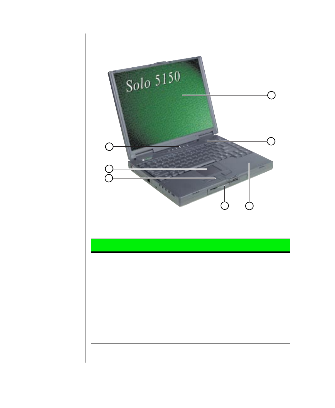
Keyboar d and LCD Panel
G
A
B
C
Component Icon Description
A. System status
indicators
(LEDs)
B. EZ Pad™ Plus
pointing device
with scroll switch
C.Mouse buttons
and rocker
switch for
scrolling
capability
LED lights that indicate the status of various
system functions. See “System Status Indicators (LEDs)” on Page 4.
Controls the cursor movement on the screen.
Use the left mouse button for left-click functionality. Use the right mouse button for rightclick functionality. The rocker switch pro vides
scrolling capability in software applications
that support it.
F
D
E
2 Using Your Gateway Solo™ 5150 Multimedia Notebook
Page 5
Component Icon Description
D.Modular option
bay
E. Built-in speakers Provides high-quality stereo sound
F. Power button Press to turn power ON or OFF. Can also be
G.Color Liquid
Crystal Display
(LCD)
Accepts the following devices: CD-ROM
drive, DVD drive, diskette drive, or LS-120
drive. The devices shipped with your system
depend on your customized order.
reproduction for software and audio CDs.
configured to Suspend/Resume mode.
Backlit anti-glare screen.
Chapter 1: Checking Out Your Notebook 3
Page 6
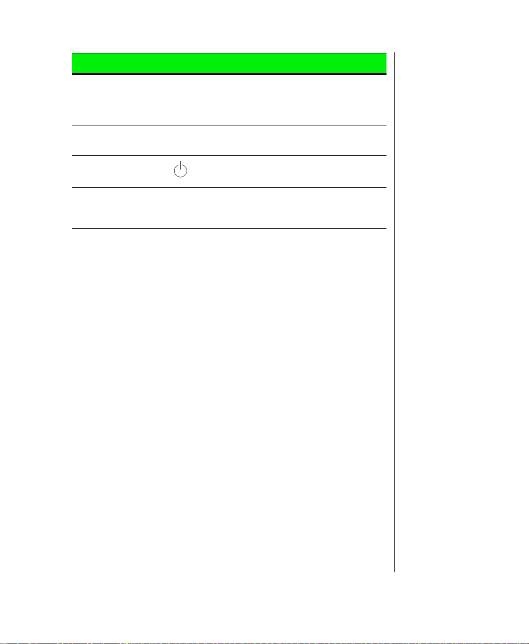
System Status Indicators (LEDs)
B
A
C
E
D
F
G
Indicator Description
A. Power indicator Indicates that the system is on.
Green means the central processing unit on the
system board (CPU) is being used.
Flashing green means the system is in suspend
mode.
Yellow mean the CPU utilization is low.
Red means a problem with the CPU. A red LED is
highly unusual. If it remains red after restarting the
system, contact technical support.
B. Hard drive Indicates that the hard drive is in use.
C.Modular option bay
access indicator
D.Caps lock Indicates that the caps lock is on. When the caps
E. Pad lock Indicates that the pad lock is on. See “Pad lock
Indicates that the device installed in the modular
option bay is in use.
lock light is on, you type in all capital letters.
keys” on Page 19.
F. Scroll lock Indicates that the scroll lock is on.
G.Battery charge
indicator
4 Using Your Gateway Solo™ 5150 Multimedia Notebook
This indicator has four modes of indication:
Green means the battery is fully charged.
Yellow indicates the battery is charging.
Red indicates a battery charging problem.
No LED means the AC adapter is not connected.
Page 7
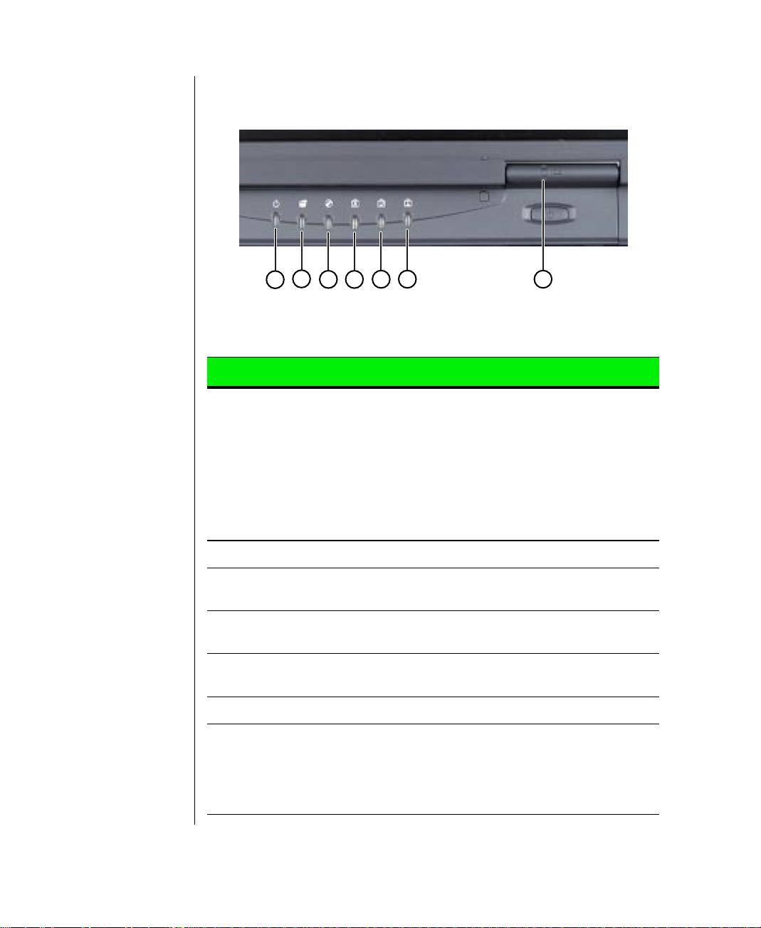
Back
A
B
C
E
D
F
Port Icon Description
A. Power connector Connect the AC power adapter to this port.
B. Parallel port
(LPT1)
C.Docking port Connect a docking station to this port.
D.Serial port Connect a serial device to this port.
E. VGA port Connect a VGA monitor cable to this port.
F. Composite
video out
Connect a parallel port device such as a
printer to this port.
Connect a cable from this port to a Video In
connector on an external video device such
as a TV or VCR to display the notebook
screen on the external video device.
Chapter 1: Checking Out Your Notebook 5
Page 8
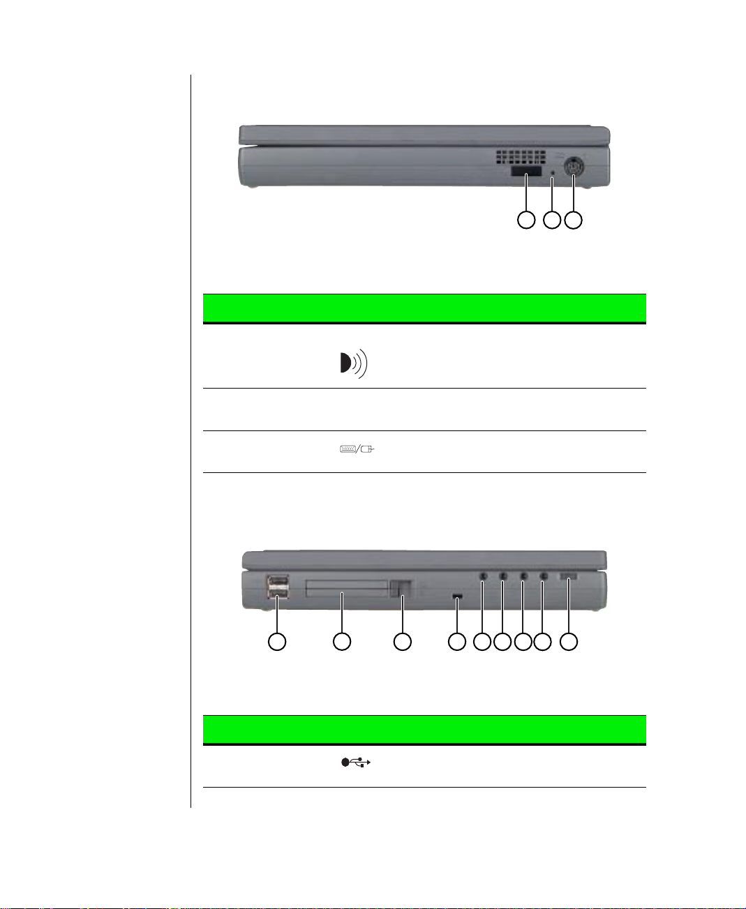
Right Side
Component Icon Description
A
B
C
A. Fast IR (Infra-
red) port
B. Reset switch Restarts the notebook if necessary. Insert a
C.PS/2 port Connect a keyboard, mouse, numeric key-
Supports an optional external infrared device
such as a printer.
paper clip to press switch.
pad, or other external device to this port.
Left Side
A
Component Icon Description
B
C
D
G
E
F
I
H
A. USB (Universal
Serial Bus) ports
6 Using Your Gateway Solo™ 5150 Multimedia Notebook
Plug USB supported devices into these
ports.
Page 9
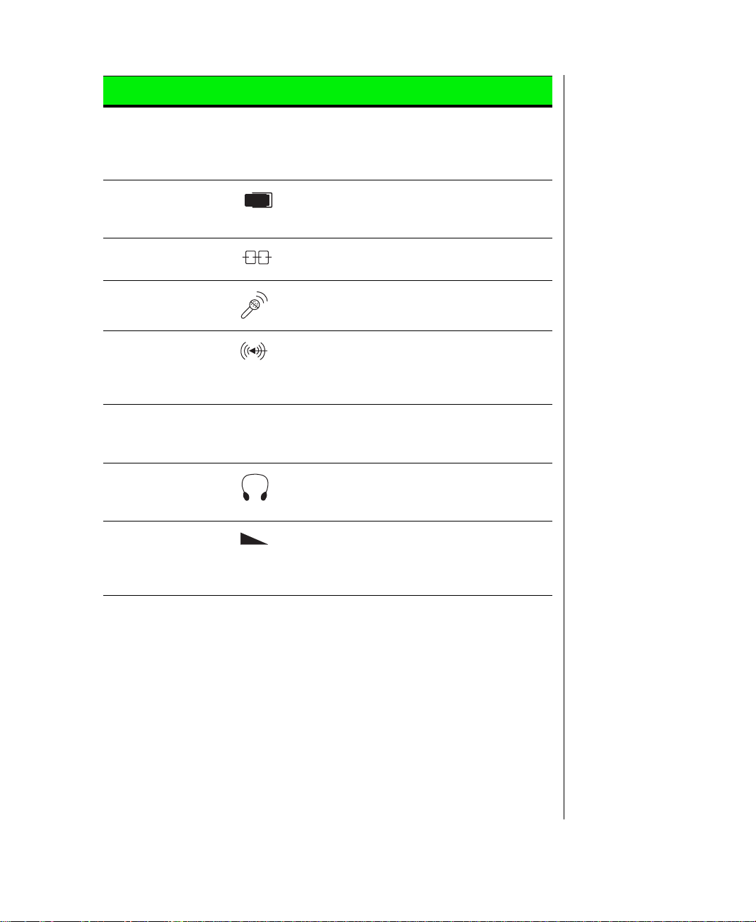
Component Icon Description
B. PC Card slots Accepts two Type I or Type II PC Cards or
one T ype III PC Card. Install Type III PC Card
in the bottom slot. Install one Zoomed Video
card in either slot.
C.PC Card eject
buttons
D.Kensington lock
slot
E. Mic in Connect an external microphone to this port
F. Line in Connect an external audio input source
G.Line out Connect amplified speakers to this port to
H.Speaker out/
Headphone jack
I. Volume wheel Adjust built-in speaker volume, external
Push in to eject the PC Card. If the button is
in the stored position, fold it out and press to
eject the PC Card.
Attach Kensington lock into this slot.
to record audio. (1/8-inch/3.5 mm jack.)
(computer, stereo, VCR, etc.) to this port to
record or play audio through the notebook
speakers (1/8-inch/3.5 mm jack.)
play audio from the notebook (1/8-inch/3.5
mm jack.)
Connect external speakers or headphones to
this port. Supports small unamplified speakers. (1/8-inch/3.5 mm jack.)
speaker, and headphone volume. Other port
volume levels are controlled by multimedia
software.
Chapter 1: Checking Out Your Notebook 7
Page 10
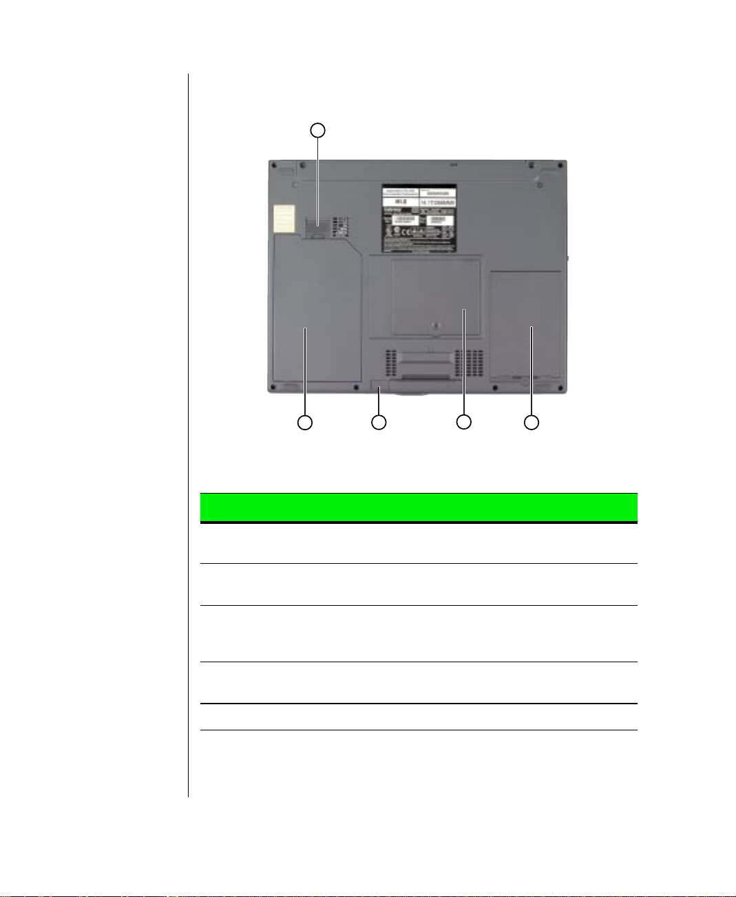
Bottom
A
B
C
D
E
Component Icon Description
A. Battery release
latch
B. Battery pack bay Slide a battery pack into bay for battery
C.Modular option
bay release
latch
D.Memory bay Open the memory bay cover to install/
E. Hard drive bay Contains the hard drive assembly.
Slide the latch to release the battery pack
from the battery pack bay.
power and battery charging.
Slide the latch to release the modular option
device so it can be swapped.
remove SO-DIMM memory modules.
8 Using Your Gateway Solo™ 5150 Multimedia Notebook
Page 11

Chapter 2:
Getting Started
Installing the battery pack ..................................... 10
Connecting the AC power.....................................12
Starting up your notebook..................................... 14
Page 12

Installing the battery pack
Your notebook is po wered b y a long-lasting battery , shipped to you partially
charged. When you first get started, you ma y want to use the A C adapter to
fully charge the battery and pro vide a constant supply of po w er while y ou
are checking out some of the notebook features.
If your battery is not installed, y ou need to install the battery pack and
charge it. You can charge the battery:
♦ When you are using your notebook with the A C adapter
♦ When the system is attached to AC po w er and in standby or suspend
mode
Note:
Battery life varies
depending on configuration,
power management
settings, and features used.
♦ When the system is attached to AC po w er and the system is turned off
The notebook can run on a fully charged battery for approximately 3.5
hours. Use the battery gauge icon in the taskbar to track the availab le
battery power . See “Monitoring the battery status” on Page 49 to learn more
about tracking battery status.
Battery life is affected by ho w much you use the system components such
as the hard drive, CD-R OM driv e, and LCD displa y, in addition to other
components such as PC Cards. Other factors such as the pow er
management settings also affect battery life. See Chapter 4, “Managing
Po w er Use” for more information about pow er management and
monitoring the battery status.
10 Using Your Gateway Solo™ 5150 Multimedia Notebook
Page 13

To install the battery pack
1.
T urn the notebook ov er .
2.
Place the battery pack into the battery bay , pushing do wnward until it
snaps into place.
Chapter 2: Getting Started 11
Page 14
Caution!
Replace the power cord if it
becomes damaged. The
replacement cord must be
of the same type and
voltage rating as the
original cord.
Warning!
Do not attempt to
disassemble the A C
adapter. The A C ad apter
has no user-replaceable or
user-serviceable parts
inside. The AC adapter has
dangerous voltages that
can cause serious personal
injury or death. Contact
Gateway about returning
defective A C adapters .
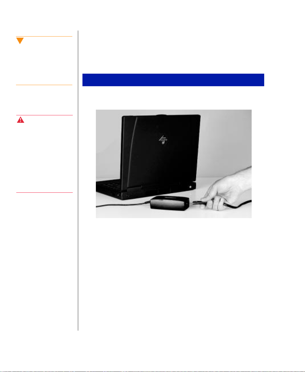
Connecting the A C power
Your A C adapter comes in tw o parts: the pow er cord and the A C po wer
adapter.
To connect the AC adapter
Connect the pow er cord to the AC pow er adapter .
1.
12 Using Your Gateway Solo™ 5150 Multimedia Notebook
Page 15
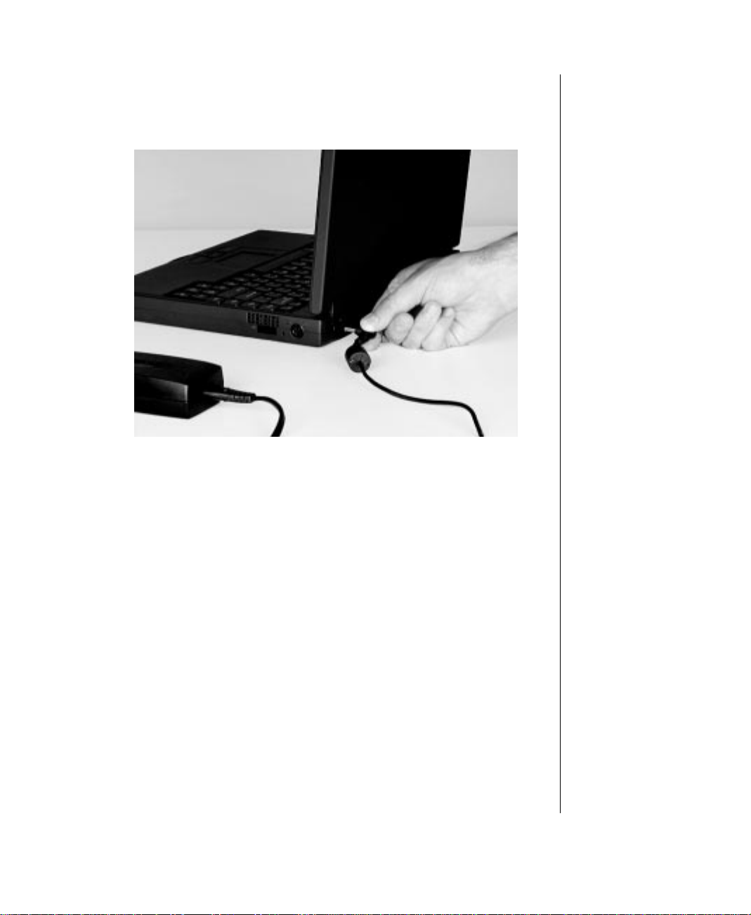
2.
Plug the AC po w er adapter into the notebook po wer connector on the
left side at the back of the notebook.
3.
Plug the pow er cord into an electrical outlet.
Chapter 2: Getting Started 13
Page 16
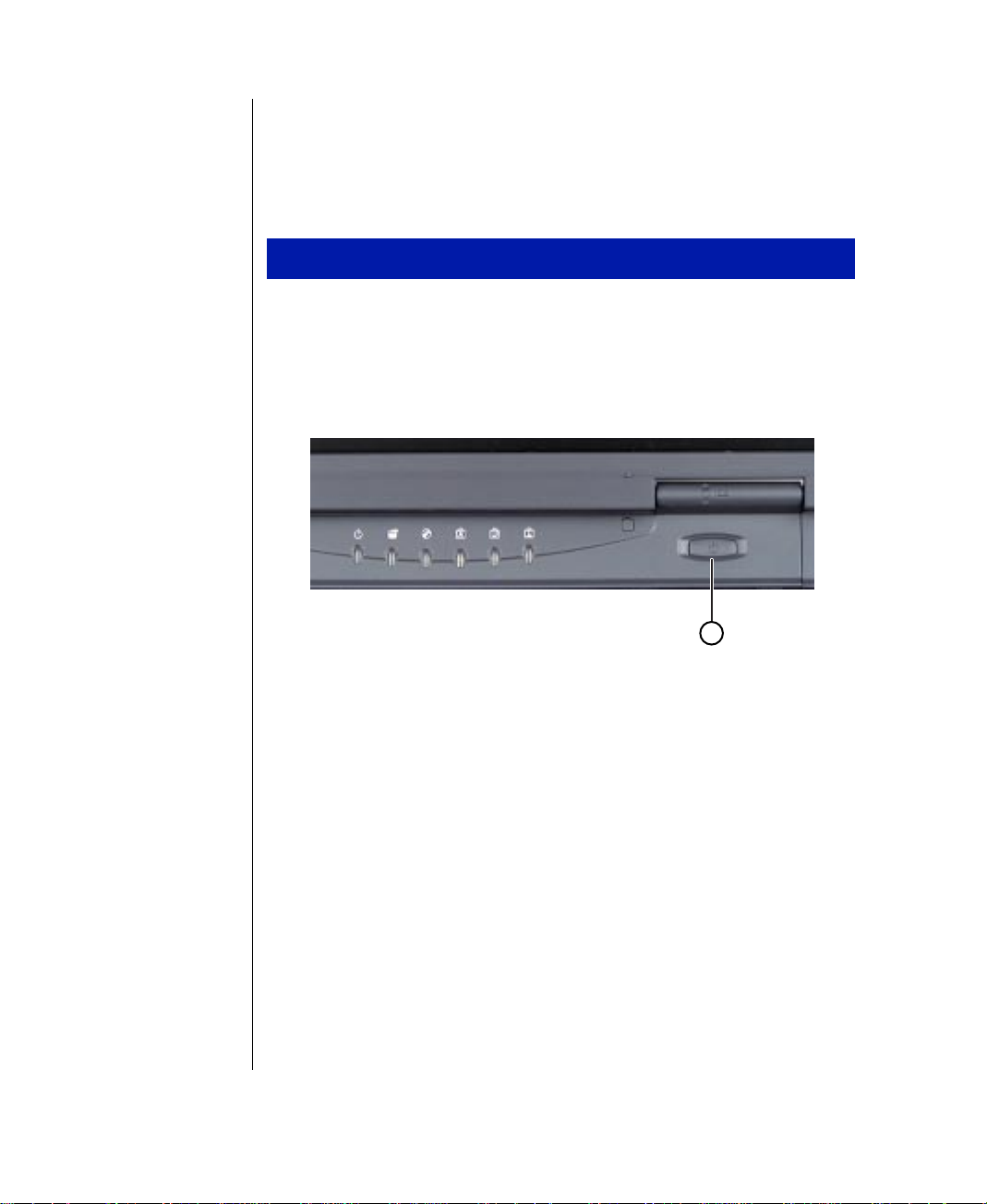
Starting up your notebook
Once the battery is installed and the AC pow er adapter is plugged in, y ou
are ready to start up your notebook.
To start up your notebook
Press in on the LCD panel latch to release and open the LCD panel.
1.
Tilt the LCD panel to adjust for the proper viewing angle.
2.
Press the pow er button.
3.
A
The pow er button is preset to On/Off mode. You can set it to function
either in On/Off or Standby/Resume mode using the BIOS setup
program. See “Modifying the pow er button mode” on Page 56 for
more information about changing power button modes.
FN+↑
Press
4.
repeatedly to get the desired brightness.
14 Using Your Gateway Solo™ 5150 Multimedia Notebook
or
FN+↓
to change display brightness. Press the arrow ke y
Page 17

Chapter 3:
Using Your Notebook
Using the keyboard................................................ 16
Using the video system.......................................... 20
Using the EZ Pad Plus Touchpad......................... 23
Using the audio...................................................... 27
Using disc media ................................................... 30
Swapping drive modules....................................... 32
Swapping hard disk drives....................................35
Using PC Cards ..................................................... 38
Using the IR port....................................................40
Using the USB ports.............................................. 41
Using McAfee VirusScan.....................................42
Page 18
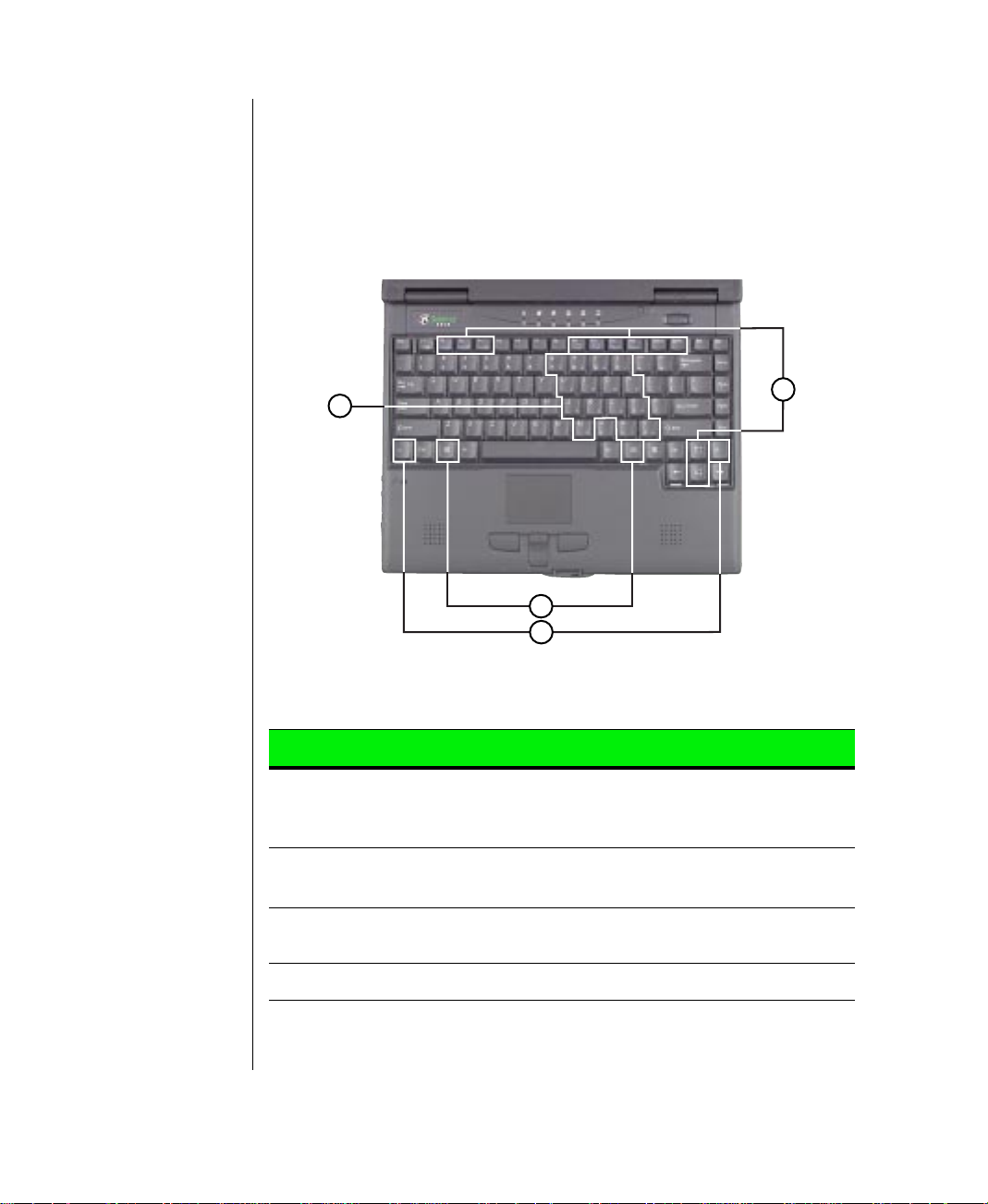
Using the keyboar d
Your notebook features a full-size keyboard that has the full functionality of
a desktop computer keyboard. Many of the ke ys hav e been assigned
alternate functions, including shortcut keys for Windows 98, function k eys
for system operations, and pad lock keys for the numeric keypad.
D
Key Action
A. Fn (function)
Combination
keys
B. Fn (function)
keys
C.Windows logo
key
F
Press
(blue) to perform a function. For example,
shows the Pop-up status display.
F
Press
F2, F3, F4
as
Press to activate the Windows
A
C
B
N
key plus one of the Fn Combination keys
FN+F2
N
key plus another Fn Combination key (such
, etc.) to perform a specific function.
button menu.
Start
D.Numeric keypad
16 Using Your Gateway Solo™ 5150 Multimedia Notebook
Press
FN+F9
to activate the numeric keypad.
Page 19
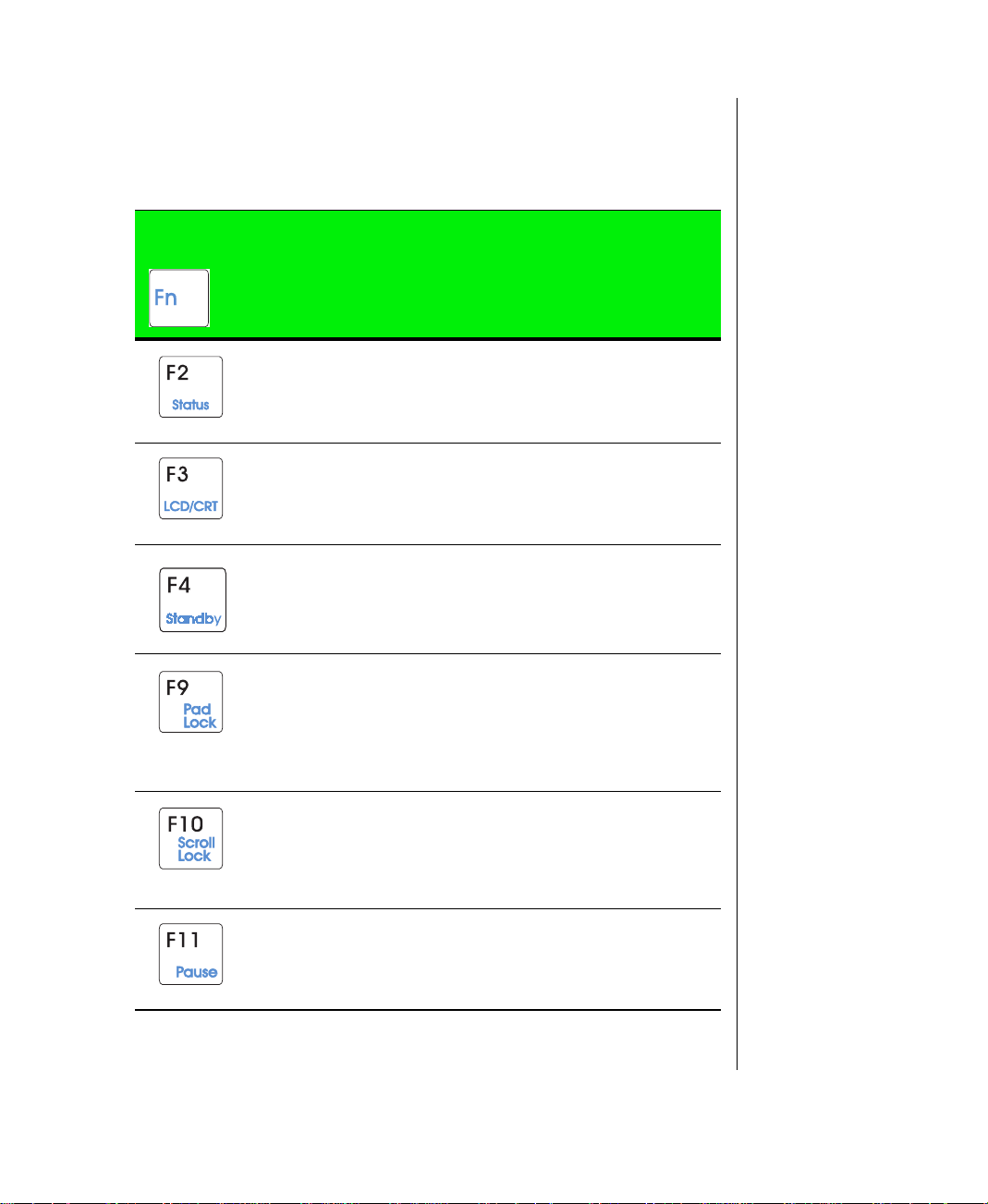
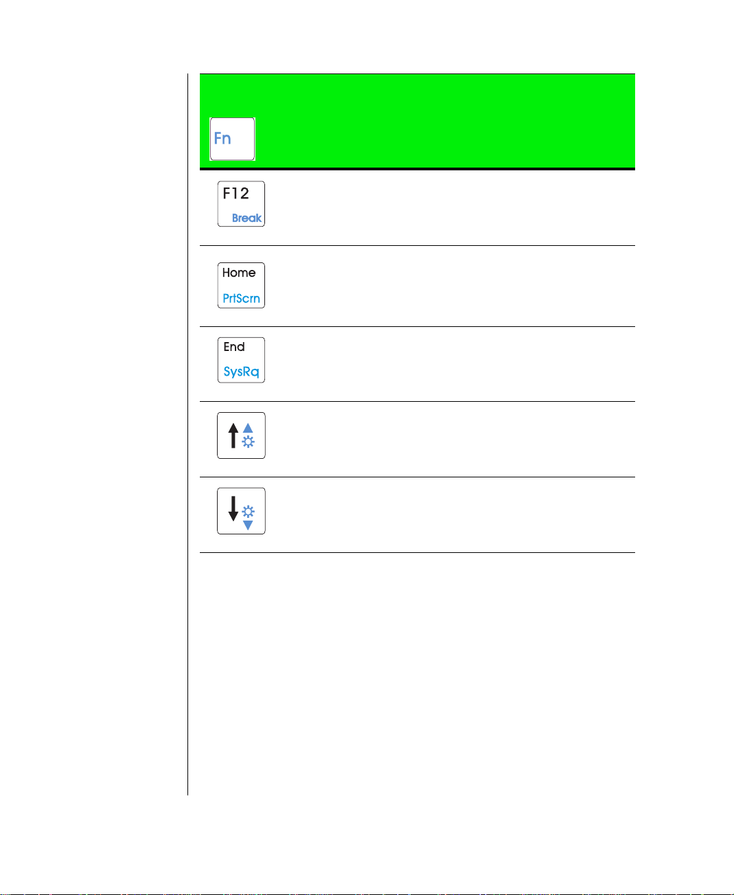
Function ke ys
N
Press the
to get these “on-the-fly” functions:
F
key together with one of the follo wing ke ys (with blue letters)
Key
Combination
+
Description
Displays the power status display for the Pop-up Status
Display program in the upper left corner of the desktop.
Press the key combination again to make the display
disappear. See “Pop-up status display” on Page 49.
T oggles between the LCD displa y , e xternal monitor, both
displays at the same time, or TV display (NTSC or PAL
format) as the active display. See “Using the video system” on Page 20.
Places the system in Standby mode. See “Using Suspend mode in Windows 95 and Windows NT” on Page
55 for more information about the Standby mode.
Enables the Pad Lock function so you can use the
numeric keypad.
The Pad Lock LED stays lit while this function is
enabled. Press the key combination again to disable
Pad Lock.
In some programs you can scroll through large volumes
of text.
The Scroll Lock LED stays lit as long as this function is
enabled.
In some programs this key combination pauses the display when text is scrolling very quickly. Press any key to
continue the text flow.
Chapter 3: Using Your Notebook 17
Page 20
Key
Combination
+
Description
In some programs this key combination pauses scrolling
text in a DOS screen.
Prints the screen if a printer is connected to your notebook (DOS only). In Windows, this key combination puts
the screen content into the clipboar d. You can then paste
it into a program such as Paint to display or print it.
SysRq (System Request) is reserved for certain applications such as in some DOS programs.
Increases LCD brightness.
Decreases LCD brightness.
18 Using Your Gateway Solo™ 5150 Multimedia Notebook
Page 21
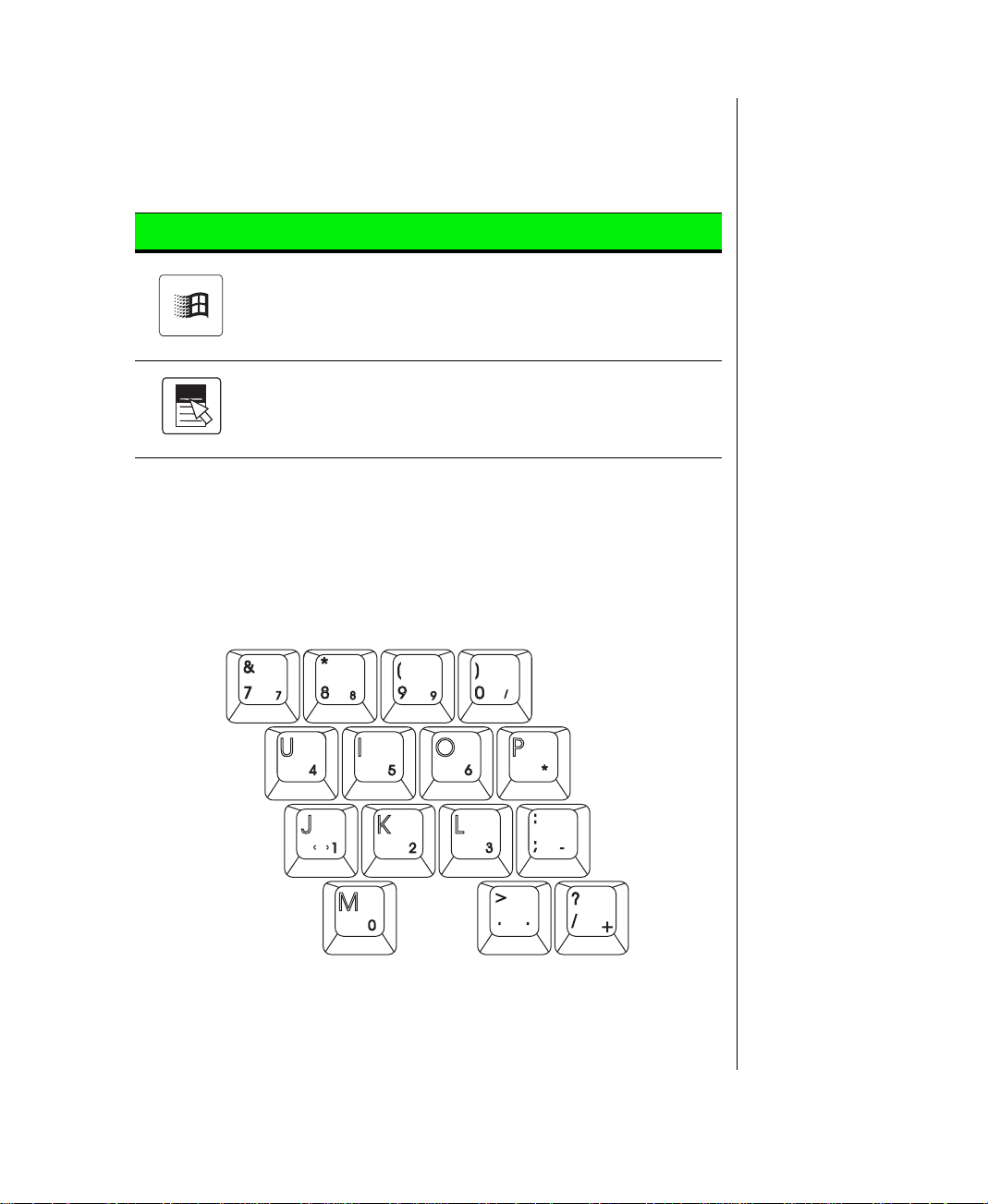
Special ke ys
The following ke ys help you use shortcuts when w orking with some
software:
Key Description
Use this key to display the Windows Start menu.
Use this key to provide quick access to application
shortcut menus and help assistants in Windows.
P ad lock ke ys
FN+F9 (PAD L
Press
the keyboard will function like a numeric keypad. Press
keyboard back into standard mode.
OCK
) keys to activ ate the keypad. The k eypad section of
FN+F9
to put the
Chapter 3: Using Your Notebook 19
Page 22
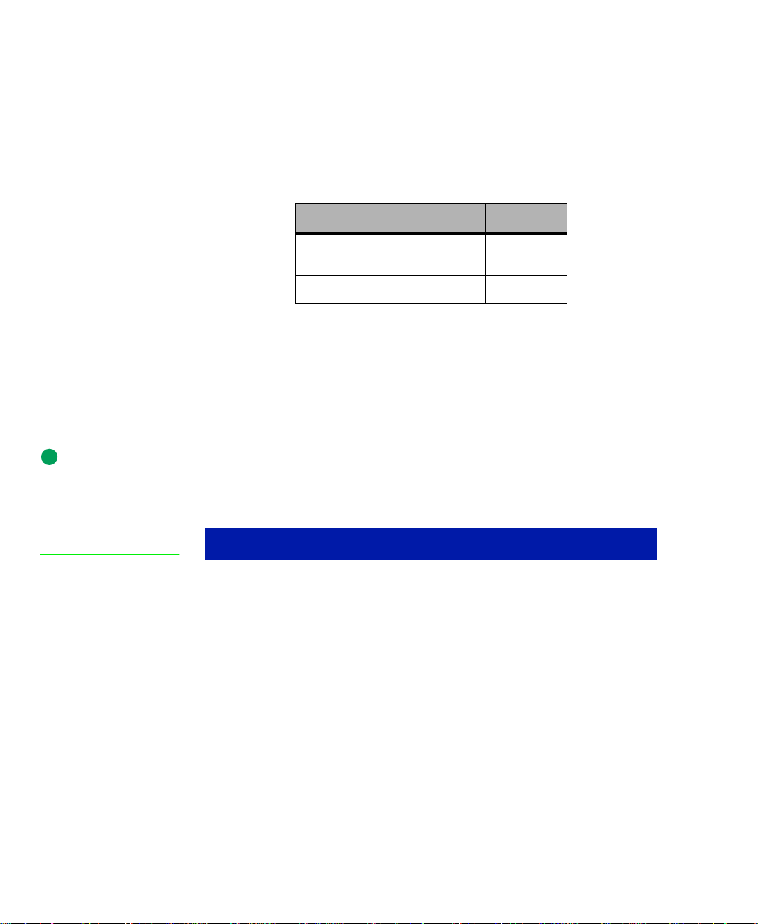
Using the video system
Your notebook features a built-in, backlit, color liquid crystal display
(LCD). The LCD uses a thin-film transistor (TFT) technology that provides
sharp resolution and brilliant colors. See the table below for the resolution
your configuration provides:
Setting 14.1 TFT
Note:
TV screen display
resolution will not be as
clear as an external monitor
because of the TV screen
display limitations.
Maximum resolution setting
(pixel column x pixel row)
Maximum color depth setting 24-bit
1024 x 768
In addition to using your LCD panel for display, you can also attach an
external monitor for presentations and other multimedia purposes. See the
next sections to learn about setting up external displays.
Setting up the composite video out port
The composite video out port lets you view your notebook's displa y on a
TV screen or record to a VCR. This option is typically used with largescreen TVs to give presentations and for other multimedia needs.
To setup and connect the computer to a TV or VCR
Start, Settings
Click
1.
and click the
Change the desktop area (display resolution) by sliding the
2.
Settings
slider to adjust pixel resolution to
Control Panel
, then
tab in the
. Double-click the
Display Properties
640 x 480
.
window.
Display
Desktop area
icon
Change the font size to
3.
Apply
Click
4.
Next, connect one end of a video cable to the composite video (TV)
5.
, then OK. Windo ws changes the displa y settings.
out port on the left side of the notebook and the other end to the video
in connector on the television or VCR.
20 Using Your Gateway Solo™ 5150 Multimedia Notebook
Large Font
.
Page 23

Press
FN+F3
to change the active displa y to LCD display, external
6.
monitor, or both displa ys at the same time as the activ e display.
Setting up an external computer monitor
You can connect an external computer monitor to your notebook through
the VGA port on the back of your notebook. If y ou are using an optional
docking station, you can also connect an external computer monitor to the
docking station VGA port.
To connect the computer to an external monitor
1.
Connect one end of a V GA cable to the V GA port on the back of the
notebook and the other end to the video connector on the monitor.
Press
FN+F3
to change the active displa y from LCD only, to LCD and
2.
monitor, or monitor onl y. Continue changing the display options until
you get the desired display.
Depending upon the external monitor you are using, you ma y ha ve to lo w er
the video resolution to 640 x 480. Refer to your monitor manual for its
display resolution capabilities.
To change the display resolution for an external monitor
1.
Right-click the
2.
Select the desired resolution. The screen resolution changes.
Monitor
icon in the taskbar tray (right bottom corner).
Chapter 3: Using Your Notebook 21
Page 24

Monitor
If the
icon does not appear on the taskbar and you want to ha ve it
appear there, follow these steps:
1.
Right-click on the desktop, and select
The Display Properties dialog bo x opens.
2.
Click the
3.
Click
The
Settings
tab.
Show settings icon on taskbar
Monitor
icon appears in the status area of the taskbar.
.
Properties
from the menu.
22 Using Your Gateway Solo™ 5150 Multimedia Notebook
Page 25

Using the EZ Pad Plus Touchpad
Like a mouse, the EZ Pad Plus touchpad controls the cursor mov ements on
the display. You can scroll, zoom, autoscroll, and pan using the rocker
switch between the mouse buttons. Scrolling capabilities are a v ailable in
some Windo ws applications, including Microsoft Of fice.
The EZ Pad Plus T ouchP ad pro vides you with fast and easy na vigation in
large documents, spreadsheets, e-mails, and on the Internet. The rocker
switch, located between the mouse buttons, lets y ou scroll, zoom,
autoscroll, and pan. Scrolling capabilities are av ailable in some W indo ws
applications, including Microsoft Office.
A
EZ Pad Plus (T ouchP ad)
A.
EZ Pad Plus rocker switch
B.
EZ Pad Plus buttons (mouse buttons)
C.
B
C
T o mo ve the cursor , press a finger lightly against the touchpad , then slide it
in the direction you want the cursor to mo v e. Press the buttons or tap on the
pad to select an object.
Chapter 3: Using Your Notebook 23
Page 26

Mouse and TouchP ad action equivalents
The basic mouse functions are illustrated and described in the following
table. T o right click, press the right mouse button instead of tapping.
Mouse Action TouchPad Action
Move cursor Slide finger
Left button
double click
Left button drag Tap and drag
Double tap finger
24 Using Your Gateway Solo™ 5150 Multimedia Notebook
Page 27

Mouse wheel and rock er switch equivalents
The following table describes using the rock er switch to perform wheel
functions.
To... Do this...
Scroll Up/Down Press forward or backward on the rocker switch to scroll
through documents.
Zoom in/out Press and hold Ctrl as you apply pressure to the rocker
switch.
Data zoom Press and hold Shift as you rock the switch to jump to a
hyperlink or return to previous Web sites using Internet
Explorer or expand or collapse menu trees in Windows
Explorer.
Autoscroll Click both sides of the rocker switch and let go once. The
document continues flowing until you use a keystroke,
mouse click, or additional rocker action to quit scrolling.
Pan Hold down both sides or the middle of the rocker switch
and swipe your finger across the touchpad to scroll quickly ,
either vertically or horizontally. Break contact with the
touchpad to quit scrolling.
Changing touchpad properties
Use the following instructions to change EZ Pad Plus properties such as
button configuration, drag, edge motion, cursor configuration, and others.
To customize the Enhanced EZ Pad
1.
2.
3.
T o find out more about using and customizing the touchpad, click the
button in the Mouse Properties dialog box.
Start, Settings
Click
In the Control Panel window, double-click the
, and
Control Panel
.
Mouse
icon.
In the Mouse Properties dialog box, click the tab of y our choice to
access and customize touchpad functions.
Help
Chapter 3: Using Your Notebook 25
Page 28

Using an external mouse or ke yboard
You can attach an external mouse or keyboard to the notebook using the PS/2
port, the USB port, or the serial port. The optional docking stations also have
ports for external connections.
It is not necessary to shut down the system to connect an external PS/2
mouse or keyboard.
If the touchpad driver does not support the external mouse, then refer to the
mouse documentation and follow the installation instructions.
26 Using Your Gateway Solo™ 5150 Multimedia Notebook
Page 29

Using the audio
Your system provides 16-bit stereo audio with SoundBlaster Pro
compatibility . You can record audio for presentations, attach voice
messages to your e-mail, listen to audio CDs, and use it for many other
multimedia applications. This section tells you more about using audio.
Adjusting the volume
There are many wa ys to adjust audio input and output on your Solo
notebook computer. The Volume Control Wheel on the left side of the
system controls the external and internal speaker volumes. The volume
level for other ports is controlled by the multimedia softw are.
To adjust playback and recording volume levels
Click
1.
The
Click the
2.
Set the
3.
Start, Settings
Multimedia Properties
Audio
tab.
Playback
and
Control Panel
and
dialog box opens.
Recording
levels to y our preference.
. Double click the
Multimedia
To adjust volume controls
Double-click the
1.
Control
dialog box.
Volume Control
A
Slide the various volume and balance controls to suit your listening
2.
requirements.
Speaker
icon in the status area to open the
dialog box opens.
icon.
Volume
Chapter 3: Using Your Notebook 27
Page 30

3.
T o customize the Volume Control dialog box, select
Properties
the Options menu.
4.
In the Properties dialog box, select the controls you w ant to be able to
adjust in the Volume Control dialog box b y clicking in the check box.
under
Note:
Connecting an external
microphone disables the
built-in microphone.
5.
T o view the adv anced controls, make sure
in the Properties Dialog box. The
Advanced
Advanced Controls
is selected
button is now displa yed in
the Volume Control dialog box.
6.
Click the
Advanced
button to view and adjust advanced settings.
Making an Audio Recording
T o make an audio recording, use the built-in microphone or connect an
external microphone to the Mic port on the left side of your notebook.
To make an audio recording
1.
2.
3.
4.
Start, Programs, Accessories, Multimedia
Click
, then
Sound Recorder opens.
Click
Edit
Audio Properties
, then
to set or check record volume leve ls.
Click OK.
Click the ● (Record) button. Recording starts.
Sound Recorder
. The
5.
When you are finished recording, click the ■ (Stop) button.
6.
7.
8.
28 Using Your Gateway Solo™ 5150 Multimedia Notebook
Click
File
, then
Save As
Type a filename for the recording.
Save
Click
.The recording is saved.
.
Page 31

Once you hav e finished recording, you can play it back using Media Play er .
To play back a recording in Media Player
1.
Start, Programs, Accessories, Multimedia
Click
Media Player opens.
2.
3.
4.
5.
6.
Click
File
, then
Open
. The
Select the file to play back.
Open
Click
.
T o pla y the file, click (Play).
T o stop the file, click ■ (Stop).
Open
dialog box appears.
, then
Media Player.
The
Chapter 3: Using Your Notebook 29
Page 32

Using disc media
Your system has a CD-ROM drive or an optional D VD-R OM dri ve. This
section describes some of the ways to use disc media for either dri ve.
To insert a disc
Press the Eject button. The drive tra y opens.
1.
Insert the disc. Press down carefully on the disc to ensure that it snaps
2.
under the clips that holds the disc in the tray.
Be sure to place the disc in the tray so that the label side is facing up. If
the disc has two pla yable sides, place the disc so that the name of the
side you want to pla y (A or B) is facing up.
Push the tray in until it clicks in the closed position.
3.
30 Using Your Gateway Solo™ 5150 Multimedia Notebook
Page 33

Playing an audio disc
The CD-ROM dri ve accepts standard music CDs. You can play and control
an audio CD using the CD Player application in W indo ws.
For information on pla ying D VD discs, see the documentation that shipped
with your D VD-R OM dri ve.
To play an audio CD
Insert an audio CD. After a fe w seconds, the CD starts playing.
1.
If the CD did not auto-start, then click
Multimedia
Click the CD Player taskbar button to use the CD Pla yer softw are.
2.
Control audio play as desired. You can change tracks, view playing
3.
, and
CD Player
to start the CD Player software.
Start, Programs, Accessories
times, control volume, set preferences, define a play list, and even set
the system to continuous or random play using this dialog bo x.
,
Chapter 3: Using Your Notebook 31
Page 34

Swapping drive modules
Your notebook features a modular option bay located in the front panel of
the notebook. This bay accepts a CD-R OM, D VD, diskette, or LS-120 drive
module.
To swap your drive modules
Close any open files and shut down your notebook.
1.
Close the cov er and turn your notebook ov er .
2.
Locate the modular bay access latch. Slide and hold the latch open and
3.
use the grip near the front of the notebook to pull the drive module out
of the notebook.
T urn your notebook back o ver.
4.
32 Using Your Gateway Solo™ 5150 Multimedia Notebook
Page 35

5.
Firmly push the drive module y ou are installing into the ba y until the
latch clicks into place and is firmly seated. If you don’ t hear the click,
try it again.
6.
Open the lid and press the pow er button to resume using your
notebook.
Chapter 3: Using Your Notebook 33
Page 36

Using the diskette disk drive e xternally
Your diskette drive module can be used as an internal or external drive.
When used as an external drive, the diskette dri ve module can be used
simultaneously with a CD-ROM/DVD/LS-120 drive module that is
installed internally .
First, install the appropriate drive module into y our notebook. Then,
connect an external diskette drive module to the parallel port at the back of
your notebook using the optional adapter cable.
It is not necessary to reboot the system for it to recognize the connection.
34 Using Your Gateway Solo™ 5150 Multimedia Notebook
Page 37

Swapping hard disk drives
You can remove the hard disk drive from y our notebook to sw ap to a second
hard disk drive.
If you decide to add a new hard disk dri ve, then use the documentation that
comes with the hard disk drive to prepare the hard disk dri ve for use.
To swap the hard disk drive
Save all w ork.
1.
Start, Shut Down, Shut down your computer?
Click
2.
Close the LCD lid.
3.
Disconnect the AC po w er (if plugged into the notebook).
4.
Remove the battery. See “T o remo ve the battery pack” on Page 47 for
5.
instructions.
T urn your notebook o ver and locate the hard disk dri ve latch.
6.
Unscrew the hard disk driv e retaining screw.
7.
, then click OK.
Chapter 3: Using Your Notebook 35
Page 38

8.
Gently pry the hard disk drive latch up and out of the seated position.
Slide the hard disk drive forw ard and lift it out of the hard disk driv e
tray.
36 Using Your Gateway Solo™ 5150 Multimedia Notebook
Page 39

9.
Place the new hard disk driv e into the hard disk driv e tray, sliding it
back into position so that the connector plug is firmly seated into the
drive’s plug-in.
10.
Seat the latch down into position and secure with the scre w.
11.
T urn the notebook o ver , reconnect the A C adapter , and replace the
battery pack.
Chapter 3: Using Your Notebook 37
Page 40

Using PC Cards
Your notebook’ s PC Card slots (also kno wn as PCMCIA card slots) are
located behind the PC Card doors on the left side of your notebook.
These slots accept two Type I or T ype II PC Cards or Type III PC Card.
Install Type III PC Card in the bottom slot. Install one Zoomed Video card
in either slot.
Your notebook is configured to automatically accept most PC Cards.
To insert a PC Card
Insert the PC Card with the label face up. If you are using a Type III
1.
PC Card , it must be inserted into the bottom slot.
Slide the card firmly into the PC Card slot. When the card is installed
2.
correctly , the computer emits a tw o-toned beep.
When a card is installed, the eject button can be folded into the system
to prevent breakage.
Follo w the W indo ws Setup W izard installation steps the first time you
3.
insert a PC Card. Operate the device as recommended in the PC Card
manufacturer’s manual.
38 Using Your Gateway Solo™ 5150 Multimedia Notebook
Page 41

To remove a PC Card
1.
Click the
2.
Click the card that you want remo v e.
3.
Click
PC Card
icon in the taskbar.
Stop
. A screen appears stating that you may safel y remo ve the
device.
4.
Click OK.
5.
If the eject button is in the stored position, fold it out and push in to
eject the PC Card.
Chapter 3: Using Your Notebook 39
Page 42

Using the IR port
The IR (infrared) port built into your notebook uses infrared technology to
send and receive signals betw een the notebook and a remote device also
equipped with an IR port.
If your notebook shipped with the IR port enabled and if you do not use the
IR port and need to make more resources (IRQs) availab le for other
devices, then use the follo wing steps to disable the IR port.
To disable the IR port
Remov e any PC Cards from the PC Card slots.
1.
Start, Settings,
Click
2.
opens.
Double-click the
3.
Click the
4.
Click + next to Infrared.
5.
Device Manager
System
in the list.
Double-click
6.
port on laptop or desktop Properties
Click to select the
7.
Click OK.
8.
Click OK on the
9.
Double-click the
10.
Infrared Monitor
Click the
11.
Clear the check box beside
12.
Built-in Infrared port on laptop or desktop
Disable in this hardware profile
Device Manager
Infrared
dialog box opens.
Options
tab.
Control Panel
then
icon. The
. The Control Panel window
System Properties
dialog box opens.
tab.
Built-in Infrared port on laptop or desktop
. The
dialog box opens.
checkbox.
tab.
icon in the Control Panel window. The
Enable infrared communication on:
appears
Built-in Infrared
COM2.
Click OK.
13.
40 Using Your Gateway Solo™ 5150 Multimedia Notebook
Page 43

Using the USB ports
USB is a new type of serial interface that serves as a single-port alternative
to connecting devices that traditionally ha ve required their o wn ports such
as mice, joysticks, ke yboards, scanners, cameras, and speakers.
T o use a USB de vice, connect it to the USB port. The USB automatically
installs and configures the necessary drivers and the system resources.
Chapter 3: Using Your Notebook 41
Page 44

Note:
We recommend that you
always scan diskettes that
you are introducing to your
system.
Using McAfee VirusScan
A computer virus is a program that attaches itself to another program on the
computer, and spreads from one pro gram to another. If transmitted
unnoticed, viruses can damage data, cause computers to crash, or displa y
bothersome or offensiv e messages. Some viruses can go unnoticed for long
periods of time because they are tied to a certain time or date before they
become active.
McAfee VirusScan is a program that helps you protect y our system from
computer viruses. Each time you start your system, McAfee VirusScan
scans your hard disk drive for viruses that could be potentiall y harmful to
your system.
If you are using diskettes to transfer information to your system, you can
run the McAfee VirusScan software on the diskette to check it before
copying files from it to your system.
To scan a diskette
Place the diskette in the diskette drive.
1.
Start, Programs, McAfee VirusScan
Click
2.
Change the C: drive setting to A: and click
3.
, and
VirusScan
All Files
.
.
4.
Click
.
Scan Now
VirusScan scans the diskette. If it finds a virus, it alerts you with onscreen instructions for removing it.
42 Using Your Gateway Solo™ 5150 Multimedia Notebook
Page 45

Updating McAfee VirusScan
Because new viruses are continually being introduced in the computer
world , a message appears appro ximately ev ery six months reminding you to
update your version of McAfee V irusScan.
Updating your version of McAfee V irusScan is important because it keeps
your virus protection current.
If you hav e a modem, an analog phone line, and a subscription to an
Internet service provider you can update McAfee V irusScan software.
Click the
Update
button and follow the on-screen instructions to complete
the update process.
Note:
You must have a modem
installed in your system and
properly connected to a
phone line to access the
Internet.
Chapter 3: Using Your Notebook 43
Page 46

44 Using Your Gateway Solo™ 5150 Multimedia Notebook
Page 47

Chapter 4:
Managing P ower Use
Using the battery.................................................... 46
Charging the battery pack..............................46
Swapping the battery pack.............................47
Monitoring the battery status ......................... 49
Managing power....................................................51
Windows 98.................................................... 51
Windows 95 and Windows NT ..................... 55
Modifying the power button mode................ 56
Maximizing the battery life............................ 56
Page 48

Using the battery
Your notebook can run on a fully charged battery for approximately 3.5
hours, depending on the type of battery you have and ho w y ou use your
notebook. Under normal operating conditions, Li-ion batteries have about
600 charge cycles before they require replacement.
Battery life is affected by ho w much you use the system components such
as the hard drive, CD-R OM driv e, or LCD display. For e xample, battery life
is increased by using the suspend function rather than a screen sav er .
Battery life is reduced by playing an audio CD while using a w ord
processor.
Other factors such as the pow er management settings affect the battery life.
See “Maximizing the battery life” on Page 56 for more information about
pow er management.
Charging the battery pack
The battery must be installed in the notebook and connected to an AC
pow er source to charge. You can charge the battery in the following modes:
♦ When you are using your notebook with the A C adapter
♦ When the system is attached to AC po w er and in standby or suspend
mode
♦ When the system is attached to AC po w er and the system is po w ered
off
You can also purchase an external battery charger or an airplane/automobile
adapter from Gatewa y Add-Ons. The ex ternal charger can charge an
additional battery while charging a battery in your notebook. The airplane/
automobile adapter lets you po wer y our notebook and charge your battery
when an A C outlet is not av ailable.
46 Using Your Gateway Solo™ 5150 Multimedia Notebook
Page 49

Swapping the battery pack
Battery packs can be “warm-swapped.” This means you can change battery
packs while in Suspend mode (Windo ws95) or Standby mode
(Windo ws 98).
The backup battery that supports warm swapping has a limited pow er
supply (about ten minutes). Make the battery swap quickl y to conserve the
backup battery power.
To remove the battery pack
1.
Save all w ork.
2.
If you are using Windo ws 98 click
Down
Standby
,
, then
OK.
The system enters standby mode.
Start
on the taskbar, then click
- OR If you are using Windo ws 95 or W indows NT click
then
Suspend
. The system enters suspend mode.
- OR Shut down the system.
3.
Close the LCD panel and turn your notebook over.
4.
Slide the battery release latch to release the battery pack.
Start
on the taskbar,
Shut
Chapter 4: Managing Power Use 47
Page 50

5.
Hold the latch back and lift the battery up out of the battery opening.
6.
Place the fresh battery pack into the battery bay , pushing do wnward
until it snaps into place.
48 Using Your Gateway Solo™ 5150 Multimedia Notebook
Page 51

Monitoring the battery status
There are many wa ys to track your battery status. Use any one of the
following battery indicators to track the battery pow er le vel.
Battery Meter icon
This icon appears in the status area of the taskbar. Doub le-click the
icon to open the Battery Meter window. The Battery Meter window tells
you what the current pow er source is and the total battery po w er remaining.
Battery
Battery charge LED
This LED is on the system status indicator panel. See “System Status
Indicators (LEDs)” on Page 4 for more information about the LED status
indicators.
P op-up status display
This pop-up display pro vides information about the battery charge and
pow er status.
FN+F2
Press
of the LCD . The menu displays status information in the follo wing order:
♦ The 1st line shows whether y ou are using an A C or DC pow er
connection.
♦ The 2nd line shows battery charge status percentage where 100%
represents a fully charged battery.
(status key) to displa y the pop-up menu in the upper left corner
♦ The 3rd line indicates the current power management setting (custom,
savings, performance, Disabled).
♦ The 4th line displays the current BIOS used on the system.
♦ The 5th line displays the keyboard controller version.
The menu stays open for about ten seconds.
Chapter 4: Managing Power Use 49
Page 52

Built-in battery meter
The battery you received with your notebook has a battery meter built into
it. T o check the status using the battery meter , remo ve the battery from the
battery pack bay (see “T o remo v e the battery pack” on Page 47) and turn it
over.
Press in on the circle indicated by the hand icon. The battery meter below
the icon lights up to indicate the percentage of battery power a v ailable.
50 Using Your Gateway Solo™ 5150 Multimedia Notebook
Page 53

Managing power
A battery-powered session for y our notebook is affected b y many things
such as using screen savers rather than the suspend function, or pla ying
music CD-ROMs wh ile using a word processor. If no AC pow er outlet is
av ailable, you w ant to make the battery-po wered session last as long as
possible.
Po w er management is handled differentl y in W indo ws 98 than in Windo ws
95 and Windo ws NT. The following tw o sections address these diff erences.
Refer to the section that applies to your operating system.
Windows 98
T o modify your po w er management settings in W indo ws 98, you do not
need to go into the BIOS program unless you want to change the po w er
button setting specifically. Instead, W indo ws 98 no w includes a P o wer
Management Properties dialog box.
To use the Power Management Properties dialog box
Click the
1.
In the Control Panel window, double-click the
2.
Click the appropriate tab to view and modify settings.
3.
Start
button,
Settings
, and
Control Panel
.
Power Management
icon.
Chapter 4: Managing Power Use 51
Page 54

P ower schemes
A pow er scheme is a set of properties selected in the Po w er Schemes
window and gi ven a name. F or e xample, the
Portables/Laptop
changes the settings to maximize battery life in your notebook system.
pow er scheme
You can select one of three existing power schemes from the
Power schemes
drop-down list.
You can also create your own po wer scheme and add it to the list.
To create a power scheme
1.
In the Po w er Schemes windo w, set the properties as you want them to
be in your po wer scheme.
2.
3.
4.
5.
Save As
Click
.
Type a name for your pow er scheme and click OK.
Select your po wer scheme from the
Click OK at the bottom of the Po w er Management Properties window
to apply the change.
52 Using Your Gateway Solo™ 5150 Multimedia Notebook
Power scheme
drop-down list.
Page 55

Alarm settings
Even though several w a ys to keep tabs on your battery po w er are a vailab le,
alarms letting you know that you might be about to lose battery po w er are
useful.
The Alarms window lets you turn off and turn on the alarms, set the point at
which your notebook alerts you that your battery is running low, and select
the notification method.
Using Standby mode in Windows 98
Windo ws 98 uses Standby mode. Standby mode is equiv alent to the
Suspend mode in Windo ws 95. When in Standby mode, your notebook
enters a sleep state according to the pow er management settings. Standb y
mode causes the system to remove po w er from most devices e xcept
memory .
The following table sho ws ho w to change the system modes in
Windo ws 98.
If your
notebook
is...
Off Start up Press the power button
...and you
want to...
Do this...
Chapter 4: Managing Power Use 53
Page 56

If your
notebook
is...
...and you
want to...
Do this...
On Standby Click
click
- OR Press
In Standby
mode
On Shut down Click
Resume
power
Press the power button briefly
again, then click
Start, Shut Down, Standby,
OK.
FN+F4
OK.
, click
Shut Down
Start, Shut Down
then
54 Using Your Gateway Solo™ 5150 Multimedia Notebook
Page 57

Windows 95 and Windows NT
T o modify your po w er management settings in W indo ws 95 and
Windo ws NT , y ou need to go into the BIOS program to change the po wer
management settings. See “Using the Po w er menu” on Page 61 for more
information on these settings and how to modify them.
Using Suspend mode in Windows 95 and Windows NT
Windo ws 95 and W indo ws NT use Suspend mode. When in Suspend
mode, your notebook enters a sleep state according to the po wer
management settings. Suspend mode causes the system to remov e pow er
from most devices except memory.
The following table sho ws ho w to change the system modes in W indo ws 95
and Windo ws NT.
If your
notebook
...and you
want to...
Do the following
is...
Off Start up Press the power button
On Suspend Click
In Suspend
mode
On Shut down Click
Resume
power
Start, Suspend
- OR -
FN+F4
Press
Press the power button briefly
Start, Shut Down, Shut down the
computer
, then click
Yes .
Chapter 4: Managing Power Use 55
Page 58

Modifying the power b utton mode
You can change the power button mode in the BIOS setup pro gram from
On/Off to Standby/Resume. See “P o w er button (switch) settings” on P age
62 for more information about accessing the BIOS Pow er menu settings to
change the pow er button mode.
Maximizing the battery life
You can extend the battery life by following these practices:
♦ Dim the display brightness as lo w as is comfortable.
♦ Close the LCD lid when not in use. The LCD display turns of f until
the lid is opened.
♦ Remov e PC Cards when not in use. Some PC Cards use battery pow er
even when the y are not in use. Check the PC Card manufacturer’s
documentation to find out if the card uses power when not in use.
♦ Keep the battery pack in the computer when using A C po wer to
continuously charge the battery.
♦ Minimize using CD-ROM dri ve. The CD-R OM dri ve uses
considerable battery pow er .
♦ Adjust the Po w er management settings most effecti vel y for the w ay
you use your notebook.
See “Managing pow er” on Page 51 for more information about
changing the pow er management settings in W indo ws 98.
See “Using the Po w er menu” on Page 61 for more information about
accessing the Po w er menu settings in the BIOS setup program for
Windo ws 95 and W indo ws NT.
56 Using Your Gateway Solo™ 5150 Multimedia Notebook
Page 59

Appendix A:
Using the BIOS Setup Program
Introduction............................................................ 58
Using the BIOS Setup Utility.........................58
Using the Power menu...................................61
Page 60

Introduction
This section contains information about the BIOS setup utility and is
intended to serve as a guide so that you can make changes to your system’s
BIOS when necessary .
The screen example that you see in this chapter is similar to what y ou see on
your LCD . Ho w ev er , you ma y ha ve a system with a ne w er BIOS version
than the one described in this manual. In that case, some of the examples
may differ some what from w hat you see. If there are dif ferences, follo w the
Item Specific Help box in the right-hand column of the BIOS Setup menu.
Using the BIOS Setup Utility
Caution!
Setting items in the BIOS
utility menus to incorrect
values may cause your
system to malfunction.
Make note of the settings
before making changes so
you can change the
settings back if necessary.
The BIOS has a built-in setup utility that lets you configure several basic
system characteristics. The settings are stored in battery-backed RAM and
are retained even w hen the po wer is of f.
To enter the BIOS Setup utility
Restart the system.
1.
Press F2 when prompted on screen during the start-up process. The
2.
Main menu opens.
58 Using Your Gateway Solo™ 5150 Multimedia Notebook
Page 61

PhoenixBIOS Setup Utility
Main Advanced Security Power Boot Exit
System Time:
System Date:
Floppy Disk Drive A:
Floppy Disk Drive B:
Primary Master
Secondary Master
Memory Cache:
System Memory:
System Information
Text Mode Expnasion:
Graphics Mode Expansion:
Boot-time Diag. Screen:
Num lock:
Display Device:
QuickBoot Mode:
[1.44MB/1.25 MB, 3 1/2]
[HH:MM:SS]
[MM/DD/YYYY]
[Disabled]
(NNN MB)
(CD-ROM)
Enabled
[Simultaneous]
[Enabled]
[Enabled]
[Enabled]
[Disabled]
Item Specific Help
NNN MB
[Off]
Note:
The Setup menu screen
shown may differ somewhat
from that shown here. If
there are differences, follow
the on-screen instructions
and helps.
F1 Help ↑↓ Select Item -/+ Change Values F9 Setup Default
ESC Exits
←→
Select Menu Enter Select > Sub-Menu F10 Save and Exit
The command bar at the bottom of the screen shows the ke ystrokes
necessary to access help, navigate through the menus, and perform other
functions.
F1 opens the Help screen, providing general help for using the
•
BIOS Setup utility .
The up arrow and down arrow ke ys select items in the menu.
•
•
Pressing S
with the + or - key changes values in fields or
HIFT
mov es an item up or down in a list.
F9 opens a screen that lets you return all values to their default
•
settings.
ESC closes the screen you are in and returns you to the previous
•
screen.
The left arrow and right arrow keys mo ve y ou betw een the five
•
menus.
E
either mov es you to a submenu screen when a selected item
NTER
•
is preceded by > or activ ates a selected field.
F10 opens a screen that lets you accept or disregard changes you
•
made and then exit the BIOS Setup utility .
Appendix A: Using the BIOS Setup Program 59
Page 62

The main screen has the following menu selections at the top of the screen:
Main gives you access to basic information and settings related to
•
your system hardware and configuration.
Advanced gi ves y ou access to information and settings for system
•
resources, hardware, and system configuration.
Security gives you access to settings related to system access
•
passwords.
Power gives you access to information and settings related to
•
pow er-sa ving functions a v ailable with your system.
Boot gives you the order of bootab le devices in the system.
•
Exit gives y ou access to options for exiting the BIOS Setup utility.
•
As you select items on the main menu and in submenus, you will see
specific information related to the current selection in the Item Specific
Help box. Refer to the help box for information about the menu options.
60 Using Your Gateway Solo™ 5150 Multimedia Notebook
Page 63

Using the P ower menu
The Po w er menu is a part of the BIOS Setup Utility that contains the pow er
management settings and system timeouts. These settings are stored and
saved e ven when the po w er is of f. Use the P ow er menu to mak e changes to
the system to improve the battery-po w ered session time and performance.
The rest of the BIOS Setup Utility screens are discussed in Maintaining and
Tr oub leshooting Your Solo Notebook.
The Po w er menu screen sho wn may dif fer some what from that sho wn here
because you may ha ve a ne w er BIOS than described here. The screens will
be similar enough to get the information you need. If there are differences,
follow the on-screen instructions and help.
To use the Power menu
1.
Start up your notebook.
2.
Press the F2 key when prompted to do so. The “Entering Setup...”
message briefly sho ws and then the Main menu appears.
3.
Use the right arrow key to navigate to the P o w er menu. Use the ke ys
identified at the bottom of the screen to navigate through the different
options. An Item Specific Help bar providing additional information
is also located along the right side of each menu.
PhoenixBIOS Setup Utility
Main Advanced Security Power Boot Exit
Item Specific
Help
Power Switch:
Lid Switch:
Low Battery Beep:
Cooling Control:
>AC Mode Power Savings
>DC Mode Power Savings
Resume On Time:
Resume on Modem Ring:
F1 Help ↑↓ Select Item -/+ Change Values F9 Setup Default
ESC Exits
Resume Time:
←→
Select Menu Enter Select > Sub-Menu F10 Save and Exit
[On/Off]
[Backlight off]
[Enabled]
[Performance]
[Off]
[00:00:00]
[Off]
Set the power button
to On/Off to work
normally. Set to
Suspend/Resume to
work as a suspend/
resume button. Hold
button 5 seconds to
shut off system.
Note:
The Pow er menu scree n
shown may differ somewhat
from that shown here. If
there are differences, follow
the on-screen instructions
and helps.
Appendix A: Using the BIOS Setup Program 61
Page 64

Note:
Turning your notebook
completely off when the
power button is set for On/
Off mode causes every part
of your notebook to turn off.
Any unsaved w ork will be
lost! Pressing the power
button will restart your
notebook.
Caution!
Any unsave d work can be
lost if you hold the pow er
button down for too long.
P ower button (s witch) settings
When the pow er switch setting in the P o w er (BIOS Setup) menu is On/Off
and your notebook is:
Off, press the pow er button to turn your notebook on.
♦
On, press the pow er button to turn your notebook completely of f.
♦
When the pow er switch setting in the P o w er menu is Suspend/Resume and
your notebook is:
Off (or in Suspend mode), press the pow er button to resume po wer to
♦
your notebook.
On, press the pow er button to cause your notebook to enter Suspend
♦
mode.
Press and hold the pow er button for about five seconds to turn your
notebook completely Off.
To change the power button setting
1.
Start up your notebook.
2.
Press the F2 key when prompted to do so. The “Entering Setup...”
message briefly sho ws and then the Main menu appears.
3.
Using the right arrow key, move to the P o wer menu.
4.
The first available option is Po w er Switch. If the setting displa yed is
the one you want, go to Step 6.
5.
Press the S
6.
Press the ESC key to access the Exit menu.
Press E
NTER
PACEBAR
to Save changes and exit, then press E
arrow key to select any other option.
62 Using Your Gateway Solo™ 5150 Multimedia Notebook
to change the setting.
or use the down
NTER
Page 65

Appendix B:
Solo Notebook Accessories
Page 66

Accessories
Note:
For more info rmation on
this or other Gateway
solutions for your notebook,
call 1(800) 846-2000.
W e of fer many accessories that can help y ou make the most of using y our
Solo notebook. Check out our web site or call our Add-Ons group to help
you find products that will best fit your needs.
Available accessories include memory modules, external keyboards,
speakers, carrying cases, printers, tape backup units, hard drives, modems,
network cards, softw are, and uninterruptable pow er supplies (UPS).
Here are more accessories we offer that mak e using your Solo more
flexible:
♦ The Docking station is a full-featured expansion unit designed to
meet the needs of mobile users who require the modularity and
functionality of a desktop system. The docking station’s key features
include two dual expansion slots (PCI or ISA), a 3.5" hard dri ve
expansion bay, a 5.25" or 3.25" device expansion ba y, two PC Card
slots, built-in stereo speakers, and a remov ab le monitor stand.
Other features are the MIDI/game port and two PS/2 ports that let you
attach devices such as an external keyboard, mouse, or joystick to the
docking station. Once you connect the peripherals, you can lea ve them
attached.
♦ The Mini-docking station enhances the capabilities of your Solo
notebook by pro viding a one-step connection to external devices such
as a monitor, ke yboard , mouse, printer , serial de vice, jo ystick, external
pow er , speakers, and microphone. The docking station also pro vides
additional PC Card slots for expanded functionality when using
network cards, SCSI adapters, and modems.
♦ Add an Extra battery for when you’re on the road and have no place
to plug in your portable. An additional Li-Ion battery will keep you
working.
♦ The Battery charger can be used to charge the Li-Ion battery for the
Solo 5150. It takes approximately two to three hours to char ge a fully
discharged battery . The battery charger has tw o LEDs to indicate
battery charge status.
64 Using Your Gateway Solo™ 5150 Multimedia Notebook
Page 67

♦ The Automobile/Airplane adapter pro vides a safe and easy w ay to
plug any Solo notebook into the industry standard EmPo w er in-seat
pow er receptacles no w a vailab le on major airlines, or into any
availab le cigarette lighter in a car , boat, or RV.
In addition to providing a safe ex ternal pow er source, the advanced,
lightweight design also allo ws you to con venientl y recharge y our
notebook’s batteries during travel.
Appendix B: Solo Notebook Accessories 65
Page 68

66 Using Your Gateway Solo™ 5150 Multimedia Notebook
Page 69

Appendix C:
Contacting Gatewa y
Contacting Gateway.............................................. 68
Calling Gateway............................................. 68
Page 70

Note:
Your Client ID number and
order number can be f ound
on your inv o ice . The se rial
number can be found on
the bottom of your
notebook.
Contacting Gateway
If you hav e any troub le while using y our Gatew ay Solo Multimedia
Notebook, please contact Gatewa y. You will need to supply your Client ID,
serial number, and order number to the customer support technicians. Make
a note of these numbers here.
If your computer is ever stolen, be sure to contact y our local police and a
Gatewa y representati ve at once. We can put a note on the account so that if
anyone calls trying to use your notebook serial number , w e can contact you
immediately.
Client ID: _____________________________
Serial Number: _________________________
Order Number: _________________________
Calling Gatewa y
Gatewa y of fers a wide range of customer service, technical support and
information services. If you have questions or problems, contact the
Gatewa y service that is most appropriate:
For assistance or
information about:
Systems, pricing,
orders, billing statements, warranty service and other nontechnical issues.
Problems with hardware or software.
The Gateway Web
site which contains a
variety of information
about Gateway.
(Modem required.)
68 Using Your Gateway Solo™ 5150 Multimedia Notebook
Contact: At:
Sales & customer
support
If outside the US,
check your warranty
booklet for numbers
Portables technical
support:
US - toll free
Canada - toll free
World Wide Web:
US and Canada http://www.gateway.com
800-846-2000
800-846-2302
800-846-3609
Page 71

Index
A
AC power
connecting
active display
application
key
arrow down
arrow up
assistance resources
automobile/airline adapter
19
18
12
21
18
68
B
batteries 64
charging
battery charger
battery latch
battery life
maximizing
battery meter
indicator
battery pack
bay
charging
installing
swapping
battery status
monitoring
BIOS
menu descriptions
setup utility
utility
brightness
display
button
power
standby/resume
10
8
10
49
8
46
10
47
49
navigating
14
3
64
49
56
58
60
60
3
C
calling Gateway 68
U.S. & Canada
68
cap lock 4
CardBus
changing
charging
client ID
65
combination
composite video out
computer viruses
connecting
contacting Gateway
contrast
38
display resolution
touchpad properties
battery
10
battery pack
68
keys
AC power
computer to TV
computer to VCR
display
16
46
20
42
12
20
68
14
21
25
20
D
decrease
LCD brightness
diskette drive
module
diskettes
scanning for viruses
display
active
brightness
changing resolution
contrast
system status
TFT
TV
docking port
docking station
32
21
20
17
14
5
18
42
14
21
49
64
Index 69
Page 72

E
eject
PC Card
external
keyboard
mouse
external monitor
changing resolution
7
26
26
21
F
F10 17
F11
17
18
F12
F2
17
F3
17
17
F4
F9
17
Fast IR
function keys
6
pad lock
pause
17,
PrtScrn
scroll lock
SysRq
18
18
16,
17
18
17
17
G
Gateway
contacting
68
H
hard disk drive 4
removing
hard disk drives
swapping
http://www.gateway.com (US site)
35
35
I
icons
increase
inserting PC Cards
installing
IR
K
Kensington lock 7
keyboard
keypad
keys
68
battery meter
docking port
Fast IR
parallel port
PS/2
serial port
VGA port
LCD brightness
battery pack
using
external
using
17
numeric
application
combination
F10
17
17
F11
F12
18
F2
17
17
F3
F4
17
F9
17
function
pad lock
PrtScrn
Windows
6
16
40
16
6
26
16,
18
5
5
16
19
16,
19
5
5
10
16
17
49
19
38
18
70 Using Your Gateway Solo™ 5150 Multimedia Notebook
Page 73

L
LCD
brightness
contrast
display
LEDs
cap lock
hard disk drive
pad lock
scroll lock
lock
Kensington
14
decrease
increase
external monitor
18
18
14
4
4
4
4
7
17
M
making an audio recording 28
managing power
maximizing
battery life
McAfee VirusScan
updating
memory bay
mini-docking station
modes
standby
suspend
Module
CD-ROM
module
diskette drive
monitor
external
TV display
mouse
external
51
56
42
43
8
64
55
55
32
32
17
17
26
N
navigating
20
60
16, 17,
BIOS utility
NTSC out
numeric keypad
O
order number 68
P
pad lock 4
56
17,
17,
19
18
17,
62
function keys
parallel port
pause
function key
PC Cards
ejecting
inserting
removing
slots
using
PCMCIA. See PC Cards
pop-up status display
portables technical support
ports
docking
Fast IR
IR
parallel
PS/2
serial
TV out
USB
VGA
power button
setting
power button settings
changing
5
7
38
39
7
38
5
6
40
5
6
5
20
41
6,
5
3
on/off
standby/resume
62
19
49
56
68
Index 71
Page 74

power management 51
Windows 95
Windows 98
Windows NT
power menu
power off from suspend mode
print screen
properties
touchpad
PrtScrn
PS/2 port
18
function key
6
55
51
55
62
18
25
18
R
removing
battery
8
hard disk drive
PC Cards
resolution
changing display
35
39
21
S
sales & customer support 68
scroll lock
serial number
serial port
setting
setup
shutdown
software
standby mode
standby/resume
starting up
status
suspend mode
4
function key
power button
standby/resume
BIOS
Windows 98
setup
5
14
58
17
68
53
17,
Windows 98
button
battery
53
3
14
49
55,
56
55
62
56
swapping
battery pack
Swapping modules
system
request
62
startup
status display
47
32
18
14
49
T
technical support 68
TFT display
touchpad
customizing
TV
connecting computer to
out port
20
25
20
20
U
Universal Serial Bus 6, 41
using
IR port
keyboard
McAfee VirusScan
mouse
PC Cards
USB
40
26
16,
42
26
38
41
V
VCR
connecting computer to
VGA port
viruses
5
scanning diskettes
scanning for
updating McAfee VirusScan
42
20
42
43
W
Windows
key
Windows 98
standby mode
16,
19
53
Z
Zoomed Video 38
72 Using Your Gateway Solo™ 5150 Multimedia Notebook
Page 75

Index 73
Page 76

Regulatory Compliance Statements
American Users:
Caution!
The Federal
Communications
Commission warns the
users that changes or
modifications to the unit not
expressly approv ed b y the
party responsible for
compliance could void the
user’s autho rity to oper ate
the equipment.
This device has been tested and found to compl y with the limits for a Class B
digital device, pursuant to Part 15 of the FCC rules. These limits are designed to
provide reasonab le protection against harmful interference in a residential
installation. This equipment generates, uses and can radiate radio frequenc y energ y
and, if not installed and used in ac cordance with the instructions, may cause
harmful interference to radio or television reception. How e ver , there is no
guarantee that interference will not occur in a particular installation. If this
equipment does cause interference to radio and television reception, which can be
determined by turning the equipment off and on, the use r is encouraged to try to
correct the interference by one or more of the follo wing measures:
♦
Reorient or relocate the receiving antenna
♦
Increase the separation between the eq uipment and recei ver
♦
Connect the equipment into an outlet on a circuit dif ferent from that to which
the receiver is connected
♦
Consult the dealer or an experienced radio/TV te chnician for help.
Accessories: This equipment has been tested and found to compl y with the limits
of a Class B digital device. The accessory associated with this equipment is the
shielded pow er cord.
This accessory is required to be used in order to ensure compliance with FCC
rules .
Canadian Users:
This digital apparatus does not exceed the Class B limits for radio noise emissions
from digital apparatus as set out in the radio interference regu lations of Industry
Canada.
Le présent appareil numérique n’émet pas de bruits radioélectriques dépassant les
limites applicables aux appareils numériques de Classe B prescrites dans le
règlement sur le brouillage radioélectrique édicté par Industrie Canada
Attention!
Couper le courant av ant l’entretien.
74 Using Your Gateway Solo™ 5150 Multimedia Notebook
Page 77

This Information T echnolog y Equipment has been tested and found to comply with
the following European d irectiv es:
[i]EMC Directiv e 89/336/EEC amending directi v e 92/31/EEC & 93/68/EEC as per
- EN 50081-1:1992 according to
EN 55022:1995 Class B
EN 61000-3-2:1995 or EN 60555-2:1986
EN 61000-3-3: 1995
- EN50082-1:1992 according to
EN 61000-4-2:1995 or IEC 801-2:1984
ENV 50140:1994 or IEC 801-3:1984
EN 61000-4-4:1988 or IEC 801-4:1998
[ii]Low Voltage Directive (Safety) 73/23/EEC as per EN 60950: 1992
European Users:
This equipment is in the Class 2 category (Information T echn olog y Equipment to
be used in a residential area or an adjacent area thereto) and conforms to the
standards set by the Voluntary Control Council for Interference by Information
T echnolo g y Equipment aimed at pre venting radio interference in such residential
area.
When used near a radio or TV receiv er , it ma y become the cause of radio
interference. Read instructions for correct handling.
This device has been tested and foun d to comply with the limits for a Class B
digital device, pursuant to the Australian/Ne w Zealand standard AS/NZS 3 548 set
out by the Spectrum Management Agenc y.
Caution!
Disconnect power bef ore servicing.
Japanese Users:
Australian and New
Zealand Users:
Regulatory Compliance Statements 75
Page 78

Notices
Copyright © 1998 Gateway 2000, In c.
All Rights Reserved
610 Gateway Drive
N. Sioux City, SD 57049 USA
All Rights Reserved
This publication is protected by copyright and all rights are reserved. No part of it may be reproduced
or transmitted by an y means or in an y f orm, without prior consent in writing from Gate way 2000.
The information in this manual has been carefully checked and is believed to be accurate. However,
changes are made periodically. These changes are incorporated in ne wer pub l icati on editi ons .
Gateway 2000 ma y im prov e a nd/or ch ange produc ts described i n this pub li cation at any t ime. Due to
continuing system improvements, Gateway 2000 is not responsible for inaccurate information which
may appear in this manual. For the latest product updates, consult the Gateway 2000 web site at
www.gateway.com
incidental, or consequential damages resulting from any defect or omission in this manual, even if
advised of the possibility o f such d amages .
In the interest of contin ued produ ct de v e lopment , Gate w a y 2000 reserv es the right to mak e
improvements in t his man ual an d the pro ducts it describes at an y time , wi thout notices o r ob ligat ion.
T r ademark Acknowledgments
AnyKey, black-and-white spot design, CrystalScan, Destinat ion, EZ Pad, EZ Point, Field Mouse, Solo ,
T eleP ath, Vivitron, stylized “G” design, and “You’ve got a friend in the business” slogan are registered
trademarks and GATEWA Y, Gateway Solo, gre en styli zed GATEWAY, g reen stylize d Gate wa y l ogo , a nd
the black-and-white spotte d bo x logo are tr ade marks of Gate w a y 2000, I nc. Int el, Int el Insi de logo, and
Pentium are registered trademarks and MMX is a trademark of Intel Corporation. Microsoft, MS, MSDOS, and Windows are tr ademarks or re gistered tr ademarks o f Micros oft Corporation. All other
product names mentioned herein are used for identification purposes only, and may be the trademarks
or registered trademarks of their respective companies.
Copyright © 1998 Advanced Logic Re sear ch, Inc. (ALR )
All Rights Reserved
9401 Jeronimo
Irvine, CA 92618 USA
. In no event will Gateway 2000 be liable for direct, indirect, special, exemplary ,
All Rights Reserved
This publication is protected by copyright and all rights are reserved. No part of it may be reproduced
or transmitted by an y me ans or in any form, without prior consent in writing f rom ALR.
The information in this manual has been carefully checked and is believed to be accurate. However,
changes are made periodically. These changes are incorporated in ne wer pub l icati on editi ons . ALR
may improv e and/ or change pro ducts d escribed i n this pu b licatio n at an y ti me. Due to co ntin uing
system improvement s, ALR is no t respon sib le f o r inaccur ate i nf ormation wh ich may appear in this
manual. For the latest product updates, consult the ALR web site at
be liable for di rect, ind irect , specia l, e xemplary , i nciden tal, or co nseque ntial damages resulting from
any defect or om ission in this ma nua l, e v en if advi sed of the possi bility o f such damages .
In the interest of continued product development, ALR reserves the right to make improvements in this
manual and the products it describes at any time, without notices or obligation.
T r ademark Acknowledgments
ALR is a registered trademark of Adv anced L ogic Researc h, Inc. Al l other pro duct names mentio ned
herein are used for ident ificat ion purposes on ly, and may be the trademarks or reg istered tr ademarks
of their respective compan ies.
76 Using Your Gateway Solo™ 5150 Multimedia Notebook
www.alr.com
. In no event will ALR
 Loading...