

Page 1

GT110 Series
User Guide
GT110
Page 2

Model Number :
Serial Number:
Purchase Date:
Place of Purchase:
© 2009. All Rights Reserved.
Gateway GT110 Series
User Guide
Gateway GT110
Page 3

iii
Information for your safety and
comfort
Safety instructions
Read these instructions carefully. Keep this document for future reference. Follow all
warnings and instructions marked on the product.
Turning the product off before cleaning
Unplug this product from the wall outlet before cleaning. Do not use liquid cleaners
or aerosol cleaners. Use a damp cloth for cleaning.
CAUTION for power cord
Observe the following guidelines when connecting and disconnecting power to the
power supply unit:
Install the power supply unit before connecting the power cord to the AC power
outlet.
Unplug the power cord before removing the power supply unit from the computer.
If the system has multiple sources of power, disconnect power from the system by
unplugging all power cords from the power supplies.
CAUTION for accessibility
Be sure that the power outlet you plug the power cord into is easily accessible and
located as close to the equipment operator as possible. When you need to
disconnect power to the equipment, be sure to unplug the power cord from the
electrical outlet.
Warnings
• Place this product in the upright position and not on its side.
• Do not use this product near water.
• Do not place this product on an unstable cart, stand or table. If the product falls,
it could be seriously damaged.
Page 4

iv
• Slots and openings are provided for ventilation to ensure reliable operation of
the product and to protect it from overheating. These openings must not be
blocked or covered. The openings should never be blocked by placing the
product on a bed, sofa, rug or other similar surface. This product should never
be placed near or over a radiator or heat register, or in a built-in installation
unless proper ventilation is provided.
• Never push objects of any kind into this product through cabinet slots as they
may touch dangerous voltage points or short-out parts that could result in a fire
or electric shock. Never spill liquid of any kind onto or into the product.
• To avoid damage of internal components and to prevent battery leakage, do not
place the product on a vibrating surface.
• Never use it under sporting, exercising, or any vibrating environment which will
probably cause unexpected short current or damage rotor devices, HDD,
Optical drive, and even exposure risk from lithium battery pack.
Using electrical power
• This product should be operated from the type of power indicated on the
marking label. If you are not sure of the type of power available, consult your
dealer or local power company.
• Do not allow anything to rest on the power cord. Do not locate this product
where people will walk on the cord.
• If an extension cord is used with this product, make sure that the total ampere
rating of the equipment plugged into the extension cord does not exceed the
extension cord ampere rating. Also, make sure that the total rating of all
products plugged into the wall outlet does not exceed the fuse rating.
• Do not overload a power outlet, strip or receptacle by plugging in too many
devices. The overall system load must not exceed 80% of the branch circuit
rating. If power strips are used, the load should not exceed 80% of the power
strip's input rating.
• This product's power supply is equipped with a three-wire grounded plug. The
plug only fits in a grounded power outlet. Make sure the power outlet is properly
grounded before inserting the power supply plug. Do not insert the plug into a
non-grounded power outlet. Contact your electrician for details.
Warning! The grounding pin is a safety feature. Using a power outlet that
is not properly grounded may result in electric shock and/or injury.
Note: The grounding pin also provides good protection from unexpected noise
produced by other nearby electrical devices that may interfere with the
performance of this product.
• Use the product only with the supplied power supply cord set. If you need to
replace the power cord set, make sure that the new power cord meets the
Page 5

v
following requirements: detachable type, UL listed/CSA certified, VDE
approved or its equivalent, 4.6 meters (15 feet) maximum length.
Product servicing
Do not attempt to service this product yourself, as opening or removing covers may
expose you to dangerous voltage points or other risks. Refer all servicing to qualified
service personnel.
Unplug this product from the wall outlet and refer servicing to qualified service
personnel when:
• The power cord or plug is damaged, cut or frayed.
• Liquid was spilled into the product.
• The product was exposed to rain or water.
• The product has been dropped or the case has been damaged.
• The product exhibits a distinct change in performance, indicating a need for
service.
• The product does not operate normally after following the operating
instructions.
Note: Adjust only those controls that are covered by the operating instructions,
since improper adjustment of other controls may result in damage and will often
require extensive work by a qualified technician to restore the product to normal
condition.
CAUTION: Danger of explosion if battery is incorrectly replaced. Replace only with
the same or equivalent type recommended by the manufacturer. Dispose of used
batteries according to the manufacturer’s instructions.
Page 6
vi
Additional safety information
Your device and its enhancements may contain small parts. Keep them out of the
reach of small children.
Disposal instructions
Do not throw this electronic device into the trash when discarding.
To minimize pollution and ensure utmost protection of the global
environment, please recycle. For more information on the Waste
from Electrical and Electronics Equipment (WEEE) regulations, visit
http://www.acer-group.com/public/Sustainability/
sustainability01.htm.
Mercury advisory
For projectors or electronic products containing an LCD/CRT monitor
or display: Lamp(s) inside this product contain mercury and must be
recycled or disposed of according to local, state or federal laws. For
more information, contact the Electronic Industries Alliance at www.eiae.org. For
lamp-specific disposal information, check www.lamprecycle.org.
Tips and information for comfortable use
Computer users may complain of eyestrain and headaches after prolonged use.
Users are also at risk of physical injury after long hours of working in front of a
computer. Long work periods, bad posture, poor work habits, stress, inadequate
working conditions, personal health and other factors greatly increase the risk of
physical injury.
Incorrect computer usage may lead to carpal tunnel syndrome, tendonitis,
tenosynovitis or other musculoskeletal disorders. The following symptoms may
appear in the hands, wrists, arms, shoulders, neck or back:
• numbness, or a burning or tingling sensation
• aching, soreness or tenderness
• pain, swelling or throbbing
• stiffness or tightness
• coldness or weakness
If you have these symptoms, or any other recur
ring or persistent discomfort and/or
pain related to computer use, consult a physician immediately and inform your
company's health and safety department.
The following section provides tips for more comfortable computer use.
Page 7

vii
Finding your comfort zone
Find your comfort zone by adjusting the viewing angle of the monitor, using a
footrest, or raising your sitting height to achieve maximum comfort. Observe the
following tips:
• Refrain from staying too long in one fixed posture.
• Avoid slouching forward and/or leaning backward.
• Stand up and walk around regularly to remove the strain on your leg muscles.
• Take short rests to relax your neck and shoulders.
• Avoid tensing your muscles or shrugging your shoulders.
• Install the external display, keyboard and mouse properly and within
comfortable reach.
• If you view your monitor more than your documents, place the display at the
center of your desk to minimize neck strain.
Taking care of your vision
Long viewing hours, wearing incorrect glasses or contact lenses, glare, excessive
room lighting, poorly focused screens, very small typefaces and low-contrast
displays could stress your eyes. The following sections provide suggestions on how
to reduce eyestrain.
Eyes
• Rest your eyes frequently.
• Give your eyes regular breaks by looking away from the monitor and focusing
on a distant point.
• Blink frequently to keep your eyes from drying out.
Display
• Keep your display clean.
• Keep your head at a higher level than the top edge of the display so your eyes
point downward when looking at the middle of the display.
• Adjust the display brightness and/or contrast to a comfortable level for
enhanced text readability and graphics clarity.
• Eliminate glare and reflections by:
• Placing your display in such a way that the side faces the window or any
light source.
• Minimizing room light by using drapes, shades or blinds.
• Using a task light.
• Changing the display's viewing angle.
• Using a glare-reduction filter.
Page 8

viii
• Using a display visor, such as a piece of cardboard extended from the
display's top front edge.
• Avoid adjusting your display to an awkward viewing angle.
• Avoid looking at bright light sources, such as open windows, for extended
periods of time.
Developing good work habits
Develop the following work habits to make your computer use more relaxing and
productive:
• Take short breaks regularly and often.
• Perform some stretching exercises.
• Breathe fresh air as often as possible.
• Exercise regularly and maintain a healthy body.
Page 9

ix
Regulations and safety notices
FCC notice
This device has been tested and found to comply with the limits for a Class A digital
device pursuant to Part 15 of the FCC rules. These limits are designed to provide
reasonable protection against harmful interference in a residential installation. This
device generates, uses, and can radiate radio frequency energy and, if not installed
and used in accordance with the instructions, may cause harmful interference to
radio communications.
However, there is no guarantee that interference will not occur in a particular
installation. If this device does cause harmful interference to radio or television
reception, which can be determined by turning the device off and on, the
user is encouraged to try to correct the interference by one or more of the following
measures:
• Reorient or relocate the receiving antenna.
• Increase the separation between the device and receiver.
• Connect the device into an outlet on a circuit different from that to which the
receiver is connected.
• Consult the dealer or an experienced radio/television technician for help.
Notice: Shielded cables
All connections to other computing devices must be made using shielded cables to
maintain compliance with FCC regulations. In compliance with FCC regulations, use
shielded cables to connect to other computing devices. A dual-link cable is
recommended for DVI output.
Notice: Peripheral devices
Only peripherals (input/output devices, terminals, printers, etc.) certified to comply
with the Class A limits may be attached to this equipment. Operation with noncertified peripherals is likely to result in interference to radio and TV reception.
Caution
Changes or modifications not expressly approved by the manufacturer could void
the user's authority, which is granted by the Federal Communications Commission,
to operate this computer.
Page 10

x
Operation conditions
This device complies with Part 15 of the FCC Rules. Operation is subject to the
following two conditions: (1) this device may not cause harmful interference, and (2)
this device must accept any interference received, including interference that may
cause undesired operation.
Notice: Canadian users
This Class A digital apparatus complies with Canadian ICES-003.
Remarque à l'intention des utilisateurs canadiens
Cet appareil numérique de la classe B est conforme a la norme NMB-003 du
Canada.
Compliant with Russian regulatory certification
Notice for Australia
For safety reasons, only connect headsets with a telecommunications
compliance label. This includes customer equipment previously labelled permitted or
certified.
Notice for New Zealand
1 The grant of a Telepermit for any item of terminal equipment indicates only that
Telecom has accepted that the item complies with minimum conditions for
connection to its network. It indicates no endorsement of the product by
Telecom, nor does it provide any sort of warranty. Above all, it provides no
assurance that any item will work correctly in all respects with another item of
Telepermitted equipment of a different make or model, nor does it imply that
any product is compatible with all of Telecom's network services.
2 This equipment is not capable, under all operating conditions, of correct
operation at the higher speeds for which it is designed. Telecom will accept no
responsibility should difficulties arise in such circumstances.
3 Some parameters required for compliance with Telecom's Telepermit
requirements are dependent on the equipment (PC) associated with this
device. The associated equipment shall be set to operate within the following
limits for compliance with Telecom's Specifications:
a There shall be no more than 10 call attempts to the same number within
any 30 minute period for any single manual call initiation, and
b The equipment shall go on-hook for a period of not less than 30 seconds
between the end of one attempt and the beginning of the next call attempt.
4 Some parameters required for compliance with Telecom's Telepermit
requirements are dependent on the equipment (PC) associated with this
device. In order to operate within the limits for compliance with Telecom's
Page 11

xi
specifications, the associated equipment shall be set to ensure that automatic
calls to different numbers are spaced such that there is not less than 5 seconds
between the end of one call attempt and the beginning of another.
5 This equipment shall not be set up to make automatic calls to Telecom's 111
Emergency Service.
6 This device is equipped with pulse dialing while the Telecom standard is DTMF
tone dialing. There is no guarantee that Telecom lines will always continue to
support pulse dialing.
7 Use of pulse dialing, when this equipment is connected to the same line as
other equipment, may give rise to bell tinkle or noise and may also cause a
false answer condition. Should such problems occur, the user should NOT
contact the telecom Fault Service.
8 This equipment may not provide for the effective hand-over of a call to another
device connected to the same line.
9 Under power failure conditions this appliance may not operate. Please ensure
that a separate telephone, not dependent on local power, is available for
emergency use.
Notice: BSMI
警告使用者:
這是甲類的資訊產品,在居住的環境中使用時,
可能會造成射頻干擾,在這種情況下,使用者會
被要求採取某些適當的對策。
Laser compliance statement
The CD or DVD drive used with this computer is a laser product.
The CD or DVD drive's classification label (shown below) is located on the drive.
CLASS 1 LASER PRODUCT
CAUTION: INVISIBLE LASER RADIATION WHEN OPEN. AVOID EXPOSURE
TO BEAM.
Appareil à laser de classe 1
Attention : Radiation laser visible et invisible en cas d’ouverture. Éviter toute
exposition aux rayons.
Laserprodukt der Klasse 1
Achtung: Beim Öffnen werden unsichtbare Laserstrahlen freigelegt. Setzen Sie sich
diesen Strahlen nicht aus.
Page 12

xii
Prodotto laser di classe 1
Attenzione: Radiazioni laser invisibili in caso d’apertura. Evitare l’esposizione ai
raggi.
Producto l
áser de Clase 1
Precauci
ón: Cuando está abierta, hay radiación láser. Evite una exposición al haz
de luz.
Produto Laser de Classe 1
Precaução: Radiação laser invisível quando aberto. Evite exposição ao feixe.
Laserproduct klasse 1
Voorzichtig: Onzichtbare laserstraling indien geopend. Voorkom blootstelling aan
straal.
Digital audio output statement
The optical connector contains no laser or light emitting diode (LED) more than
Class I.
Radio device regulatory notice
Note: Below regulatory information is for models with wireless LAN and/or
Bluetooth only.
General
This product complies with the radio frequency and safety standards of any country
or region in which it has been approved for wireless use. Depending on
configurations, this product may or may not contain wireless radio devices (such as
wireless LAN and/or Bluetooth modules). Below information is for products with such
devices.
Declaration of Conformity for EU countries
Hereby, Acer, declares that this system is in compliance with the essential
requirements and other relevant provisions of Directive 1999/5/EC.
List of applicable countries
This device must be used in strict accordance with the regulations and constraints in
the country of use. For further information, please contact local office in the country
of use. Please see http://ec.europa.eu/enterprise/rtte/implem.htm for the latest
country list.
Page 13

Contents
1 System tour 1
External and internal structure 2
Front panel 2
Rear panel 3
Internal components 4
System boards 6
Mainboard 6
System jumpers 9
Clear CMOS 9
BIOS recovery 9
System LED indicators 10
Front panel LED indicators 10
Gigabit LAN port LED indicators 11
2 System setup 13
Setting up the system 14
Pre-installation requirements 14
Connecting peripherals 15
Turning on the system 16
Power-on problems 17
Configuring the system OS 18
Turning off the system 19
3 System upgrades 21
Installation precautions 22
ESD precautions 22
Pre-installation instructions 22
Post-installation instructions 23
Opening the server 24
Removing the side panel 24
Installing the hard drive 25
Installing a 3.5" HDD 25
Installing a 5.25" storage device 26
Upgrading the processor 29
Upgrading the system memory 34
Installing an expansion card 38
4 System BIOS 41
BIOS overview 42
Entering BIOS setup 43
BIOS setup primary menus 43
Page 14

xiv
BIOS setup navigation keys 43
Main menu 45
Advanced menu 46
Advanced Processor Configuration 47
Memory Configuration 49
Advanced Chipset Control 50
PCI Configuration 52
IDE Configuration 53
I/O Device Configuration 54
Boot Configuration 55
Security menu 56
Setting a system password 57
Changing a system password 57
Removing a system password 58
Server menu 59
System Management 59
Console Redirection 61
Boot menu 63
Exit menu 64
5 System
troubleshooting 65
Resetting the system 66
Initial system startup problems 67
Initial troubleshooting checklist 67
Hardware diagnostic testing 69
Checking the boot-up status 69
Verifying the condition of the storage devices 69
Confirming loading of the operating system 70
Specific problems and corrective actions 70
Appendix A: Server management tools 75
Server management overview 76
RAID configuration utilities 77
Onboard SATA RAID Configuration Utility 77
Appendix B: LSI RAID configuration 79
LSI MegaRAID SAS 8204ELP RAID Configuration Utility 80
Index 83
Page 15

1 System tour
Page 16
1 System tour
2
External and internal structure
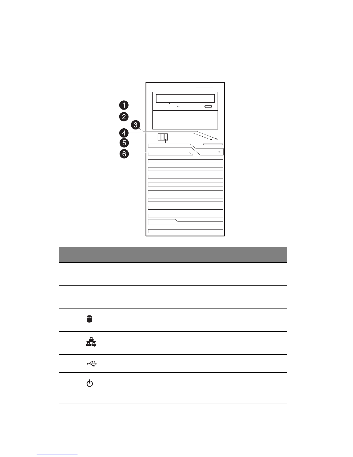
Front panel
No. Icon Component Description
1 DVD-ROM drive Disk drive for reading CD, VCD, and
DVD content
s.
2 5.25" drive bay Allows installation of additional
sto
rage devices.
3
HDD activity indicator Indicates the status of a system hard
drive (blue).
4
LAN status indicator Indicates the system network
connection status.
5
USB 2.0 ports Connect to USB devices.
6
Power button and
power indicator
Press to turn the server on/off, or to
put it in standby mode. Indicates the
power status.
Page 17
3
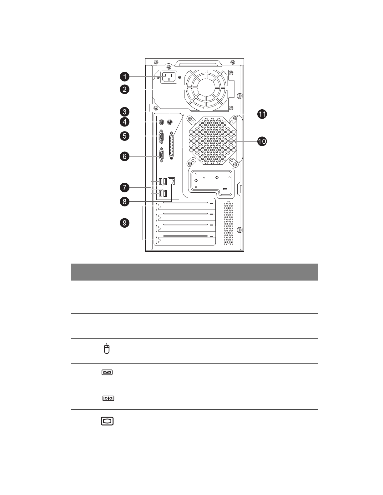
Rear panel
No. Icon Component Description
1 Power supply
module
cord
socket
Connect the system power cord here.
2 Main power
supply module
Provides the system’s main power
su
pply.
3
PS/2 mouse
port
Connects to a PS/2 mouse.
4
PS/2 keyboard
port
Connects to a PS/2 keyboard.
5
Serial port Connects to serial devices.
6
Monitor port Connects to monitors.
Page 18
1 System tour
4
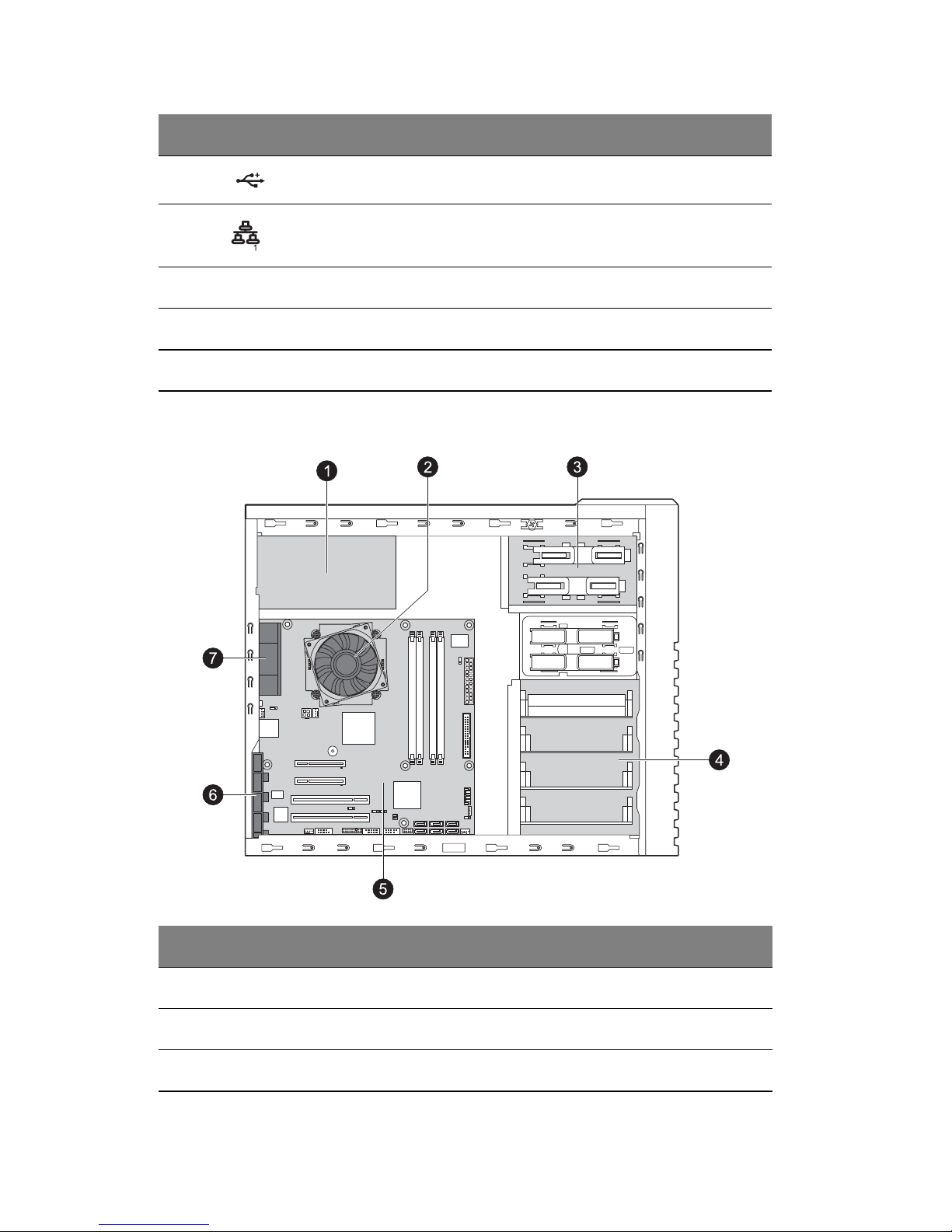
Internal components
7 USB 2.0 ports Connect to USB devices.
8
Gigabit LAN
port
Connects to an internet or intranet
network.
9 PCI slot covers Protect the vacant expansion slots.
10 System fan Regulates the system airflow.
11 Parallel port Connects to parallel devices.
No. Component
1 Power supply
2 Heat sink fan (HSF) assembly
3 Sliders for the 5.25" devices
No. Icon Component Description
Page 19

5
4 HDD carriers
5 Mainboard
6 PCI slot lock
7 System fan
No. Component
Page 20
1 System tour
6
System boards
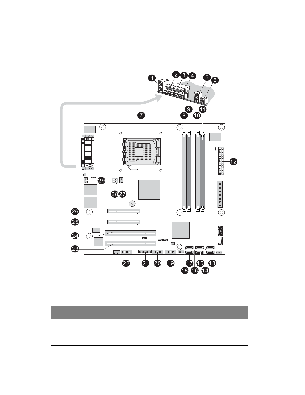
Mainboard
No. Code Description
1 PS/2 ports Connect to PS/2 mouse and keyboard.
2 Serial port Connects to serial devices.
3 Parallel port Connects to parallel devices.
Page 21

7
4 VGA port Connects to monitors.
5 RJ45/USB ports The RJ45 port connects to an internet or
intranet network. The USB ports connect
to USB devices.
6 USB ports Connect to USB devices.
7 CPU Processor socket
8 DDR2 A1 DIMM slot
9 DDR2 A2 DIMM slot
10 DDR2 B1 DIMM slot
11 DDR2 B2 DIMM slot
12 24-pin ATX Power connector
13 SATA 1 SATA cable connector
14 SATA 0 SATA cable connector
15 SATA 3 SATA cable connector
16 SATA 2 SATA cable connector
17 SATA 5 SATA cable connector
18 SATA 4 SATA cable connector
19 F_USB2 Front USB2 cable connector
20 F_USB1 Front USB1 cable connector
21 F_Panel Front panel connector
22 COM2 Connects to serial port
23 PCI_B PCI slot (32-bit/33MHz)
24 PCI_A PCI slot (32-bit/33MHz)
25 PCI-E 2 PCI-E x8 slot (x4 bandwidth)
No. Code Description
Page 22

1 System tour
8
26 PCI-E 1 PCI-E x8 slot
27 CPU_FAN CPU fan cable connector
28 8-pin ATX Power connector
29 SYS_FAN System fan cable connector
No. Code Description
Page 23
9
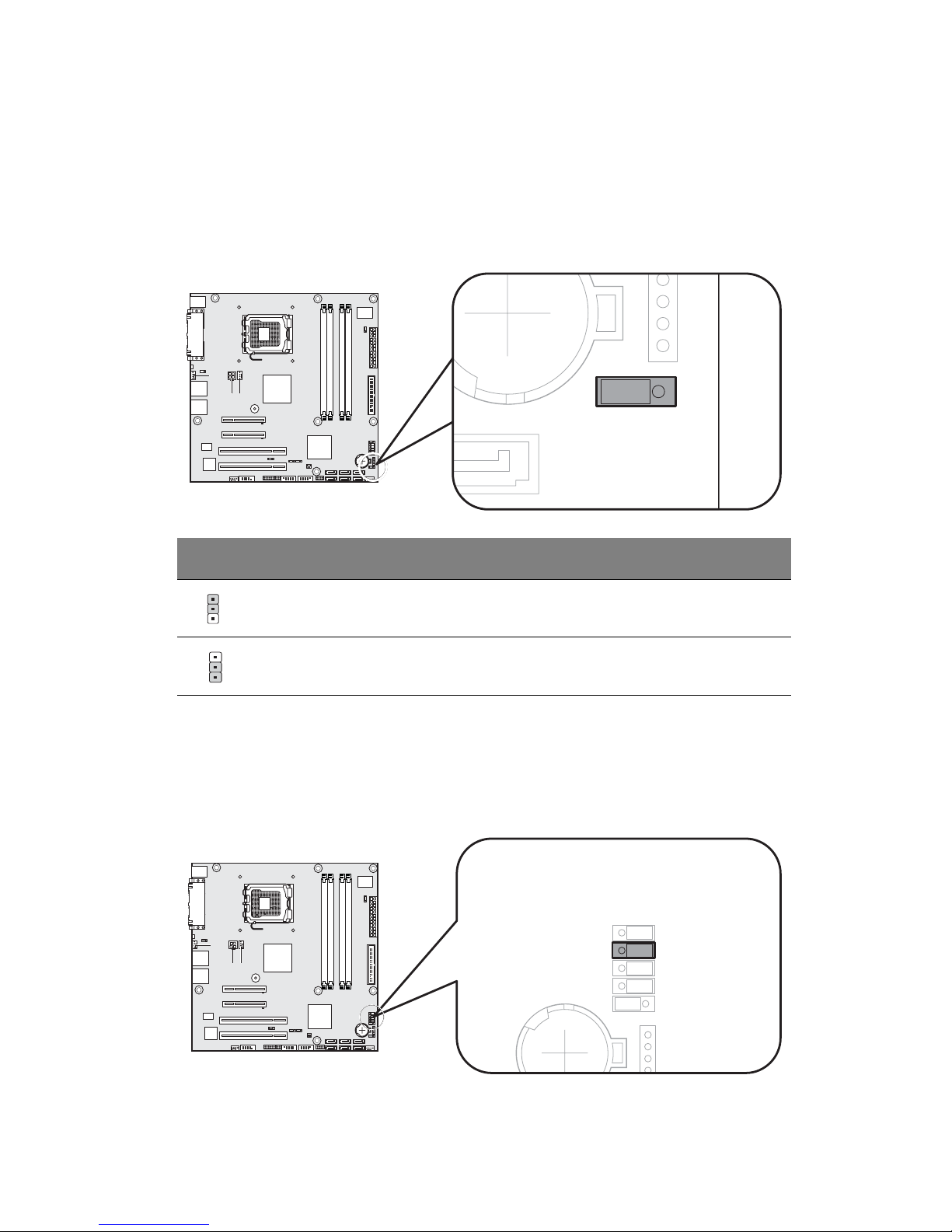
System jumpers
Clear CMOS
You may clear the CMOS data to its default value by shorting the 2-3 pins.
BIOS recovery
You may put the computer into BIOS recovery mode by shorting the 2-3
pins.
Jumper position Status
1-2 close: Normal (default setting).
2-3 close: Clear CMOS.
1
1
Page 24
1 System tour
10
System LED indicators
This section discusses the different LED indicators located on the:
• Front panel
• LAN port
Knowing what each LED indicator signifies can aid in problem diagnosis
and
troubleshooting.
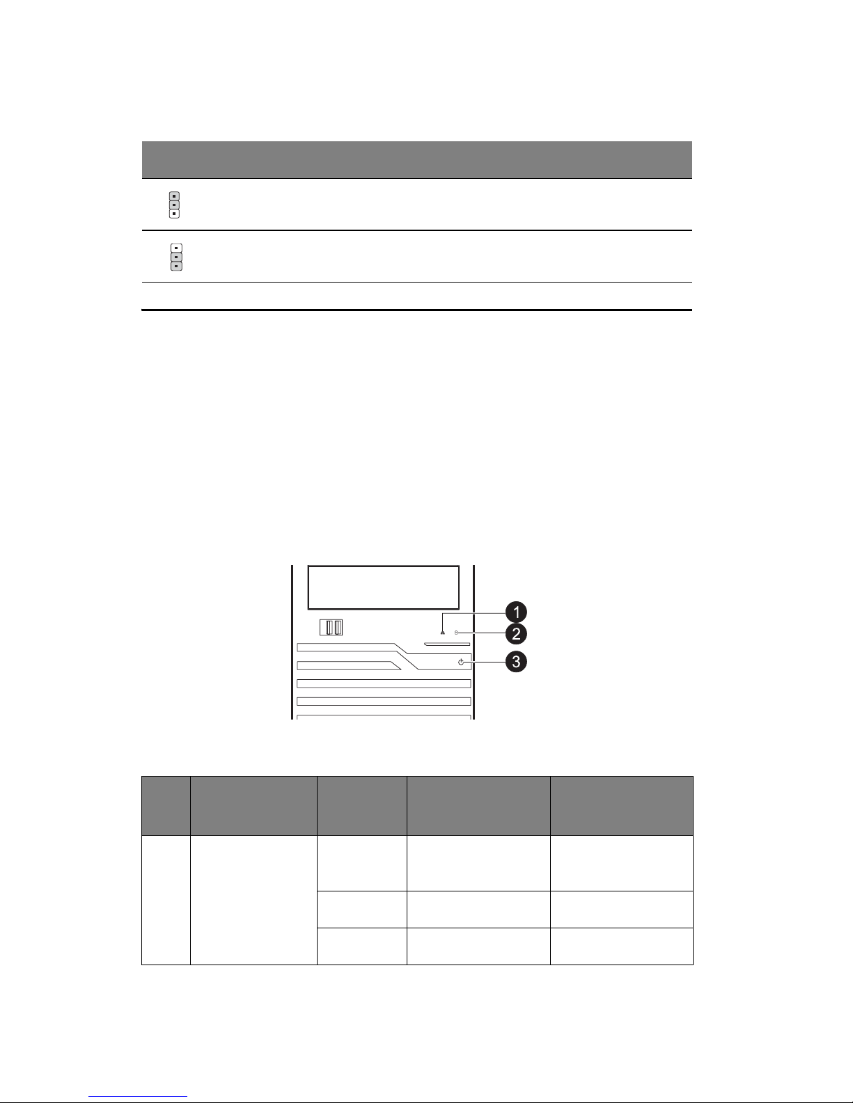
Front panel LED indicators
There are three LED indicators mounted on the front bezel.
Jumper position Status
1-2 close: Enable BIOS recovery.
2-3 close: Normal (default setting).
No. Indicator Color State Representative
Status
1 LAN activity Blue On LAN link or no
access
Blue Flashing LAN access
N/A Off Disconnect or idle
1
1
Page 25

11
No. Indicator Color State Representative
Status
2 HDD activity Blue Flashing HDD access
N/A Off No access and no
HDD fault
3 Power Blue On S0: Power on
Blue Flashing (1 Hz
with at 50% duty
cycle)
S1: Sleep
N/A Off S4/S5
Page 26

1 System tour
12
Gigabit LAN port LED indicators
LED
Indicator
LED
Color
LED State NIC State
LED 1 Off 10 Mbps connection
Off Port identification with 10 Mbps
connection
Green On 100 Mbps connection
Green Flashing Port identification with 100 Mbps
connection
Yell ow On 1 Gbps connection
Yell ow Flashing Port identification with 1 Gbps
connection
LED 2 Green On LAN link / no access
Green Flashing LAN access
Off Idle
Page 27

2 System setup
Page 28

2 System setup
14
Setting up the system
Pre-installation requirements
Selecting a site
Before unpacking and installing the system, select a suitable site for the
system for maximum efficiency. Consider the following factors when
choosing a site for the system:
• Near a grounded power outlet.
• Clean and dust-free.
• Stable surface free from vibration.
• Well-ventilated and away from sources of heat.
• Secluded from electromagnetic fields produced by electrical devices
such as air conditioners, radio and TV transmitters, etc.
Checking the package contents
Check the following items from the package:
• GT110 system
• Gateway Smart Setup DVD Pack
• GT110 accessory box
If any of the above items is damaged or missing, contact your dealer
immediately.
Save the boxes and packing materials for future use.
Page 29

15
Connecting peripherals
The I/O port panel on the system rear accepts a variety of compatible
peripherals. Refer to the figure below for specific connection instructions
for each port.
Note: Consult the operating system manual for information on how to
configure the network setup.
Caution: Do not route the power cord where it will be walked on or
pinched by items placed against it. The server is designed to be
electrically grounded (earthed). To ensure proper operation, plug the
power cord into a properly grounded AC outlet only.
Page 30
2 System setup
16
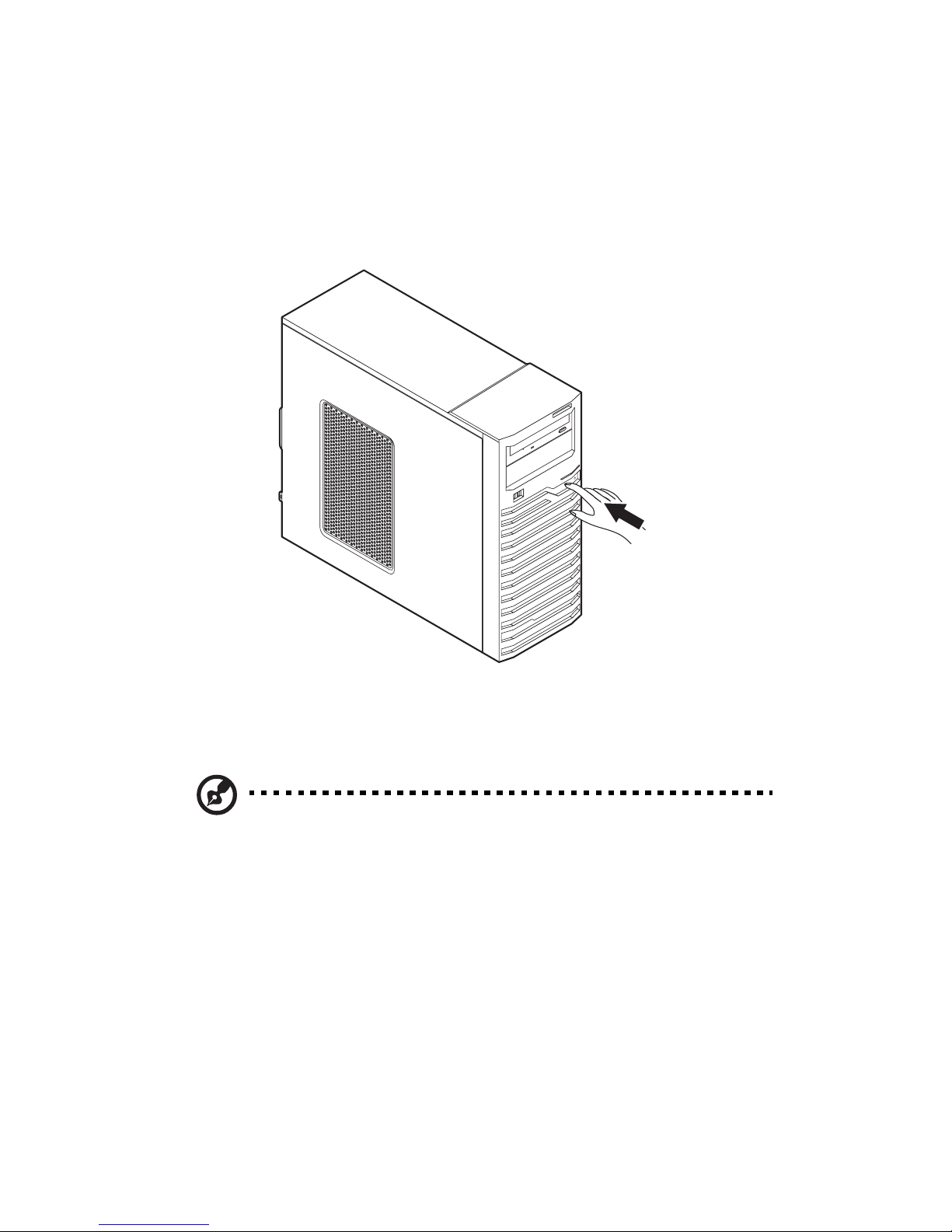
Turning on the system
After making sure that you have properly set up the system, applied power
and connected all the necessary peripherals, you can now power on the
system. Follow the procedure below.
1 Press the power button.
The system starts up and displays a welcome message on the
monitor
. After that, a series of power-on self-test (POST) messages
appears. The POST messages indicate if the system is running well or
not.
Note: If the system does not turn on or boot after pressing the power
button, go to the next section for the possible causes of the boot
failure.
Aside from the POST messages, you can determine if the system is in
good condition by checking if the following occurred.
• The power status indicator on the front panel lights up blue.
• The Num Lock, Caps Lock and Scroll Lock indicators on the keyboard
lig
ht up.
Page 31

17
Power-on problems
If the system fails to boot after you have applied power, check the following
factors that might have caused the boot failure.
• The external power cord may be loosely connected.
Check the power cord connection from the power outlet to the power
cord socket on the rear panel. Make sure that the cord is properly
connected to the power outlet and to the power cord socket.
• No power comes from the grounded power outlet.
Have an electrician check your power outlet.
• Loose or improperly connected internal power cables.
Check the internal cable connections. If you are not confident to
perform this step, ask a qualified technician to assist you.
Warning! Make sure all power cords are disconnected from the
electrical outlet before performing this task.
Note: If you have gone through the preceding actions and the system
still fails to boot, ask your dealer or a qualified technician for
assistance.
Page 32

2 System setup
18
Configuring the system OS
The GT110 comes with Gateway Smart Setup that allows you to
conveniently install the preferred operating system. To start using Gateway
Smart Setup, follow the steps below.
1 Locate the Gateway Smart Setup DVD included in the system
package.
2 With the system turned on, press the DVD-ROM drive Eject button.
3 When the disc tray slides open, insert the Gateway Smart Setup DVD
with the label side of the disc facing upward.
Note: When handling the disc, hold it by the edges to avoid smudges
or fingerprints.
4 Press the drive Eject button again to close the disc tray.
5 The Gateway Smart Setup sequence begins. Follow all onscreen
instructions.
For more information, refer to the Gateway Smart Setup Installation guide.
Note Gateway Smart Setup only supports the Microsoft and Red Hat
Linux operating systems. The Windows or Red Hat installation disc(s)
is required to install the OS.
Page 33

19
Turning off the system
There are two ways to turn off the server—via software or via hardware.
The software procedure below applies to a system running on a Windows
OS. For other shutdown procedures, refer to the related user
documentation.
To turn off the system via software:
1 Press <Ctrl> + <Alt> + <Delete> on the attached keyboard or click
Start on the Windows taskbar.
2Select Shut Down.
3Select Shut Down from the drop-down menu, then click OK.
To turn off the system via hardware:
If you cannot shut down the server via software, press the power button for
at least four seconds. Quickly pressing the button may put the server in a
Suspend mode only.
Page 34

2 System setup
20
Page 35

3 System upgrades
Page 36

3 System upgrades
22
Installation precautions
Before you install any server component, it is recommended that you read
the following sections first. These sections contain important ESD
precautions along with pre-installation and post-installation procedures.
ESD precautions
Electrostatic discharge (ESD) can damage static-sensitive hardware
components, such as the processor, disk drives, and the system board.
Always observe the following precautions before you install a server
component:
• Do not remove a component from its protective packaging until you are
ready to install it.
• Do not touch the component pins, leads, or circuitry.
• Components with a Printed Circuit Board (PCB) assembly should
always be laid with the assembly-side down.
• Wear a wrist grounding strap and attach it to a metal part of the server
before handling components. If a wrist strap is not available, maintain
contact with the server throughout any procedure requiring ESD
protection.
• Keep the work area free of nonconductive materials, such as ordinary
plastic assembly aids and foam packing.
Pre-installation instructions
Perform the steps below before you open the server or before your remove
or replace any component.
Warning! Failure to properly turn off the server before you start
perform any hardware configuration may cause serious damage
and bodily harm. Do not attempt the procedures described in the
following sections unless you are a qualified service technician.
1 Turn off the server and all connected peripherals.
2 Unplug all power cables from their outlets.
3 Disconnect all telecommunication cables from their ports.
4 Place the server on a flat, stable surface.
Page 37

23
5 Open the server according to the instructions on page 24.
6 Follow the ESD precautions described in the previous section when
handling a server component.
Post-installation instructions
Perform the steps below after installing a server component.
1 See to it that all components are installed according to the described
step-by-step instructions.
2 Reinstall any expansion board(s), peripheral(s), bracket(s) and system
cable(s) that have previously been removed.
3 Reinstall the side panel.
4 Reconnect the power, peripheral, and telecommunication cables.
5 Turn on the system.
Page 38

3 System upgrades
24
Opening the server
Caution: Before you proceed, make sure that you have turned off the
system and all peripherals connected to it. Read the
Pre-installation instructions section on page 22.
You need to open the server before you can install upgrade components.
The left side panel is removable to allow access to the server’s internal
components. Refer to the following sections for instructions.
Removing the side panel
1 Perform the pre-installation instructions described on page 22.
2 Remove the two thumb screws on the back panel (1).
3 Slide the locking switch down (2) and slide the side panel toward the
rear
of the chassis to disengage it (3).
Page 39

25
Installing the hard drive
The GT110 accommodates up to four 3.5" SATA or SAS hard disk drives.
Note: Max HDD support is SKU dependent.
Installing a 3.5" HDD
1 Perform the pre-installation instructions described on page 22.
2 Remove the side panel described on page 24.
3 Remove an available HDD carrier from the side of the chassis.
Press tabs together and pull the carrier out.
4 Slide the hard disk into the HDD carrier (1), making sure the tabs are
lin
ed up (2).
5
Pull carrier over the HDD (3) and secure tabs into place (4).
Page 40

3 System upgrades
26
6 Insert the new hard drive into the case.
Note: Recommended HDD installation order is from bottom to top.
1
2
3
4
Slide the drive into the case until the carrier tabs snap into place.
7 Connect the power and SATA/SAS cables to the new HDD.
8 Observe the post-installation instructions described on page 23.
Installing a 5.25" storage device
The two 5.25" device bays support a variety of storage devices for
additional storage capacity and scalability.
By default, the system ships with a DVD-ROM drive installed on the
topmost device bay. You can choose to replace these default drives, or you
can install a new storage device on the second device bay.
Page 41

27
Please ensure all installed devices support the SATA interface.
To install a 5.25" storage device:
1 Perform the pre-installation instructions described on page 22.
2 Remove the side panel described on page 24.
3 Remove the 5.25" bay cover (1) and EMI protector (2).
4 Slide the tool-less bracket to the
left to unlock the bay (3).
5 Insert the new 5.25" storage device (1) and slide the tool-less bracket
to the right in the locked position (2).
Page 42

3 System upgrades
28
6 Connect the power (3) and SATA cables (4) to the new 5.25" drive.
7 Observe the post-installation instructions described on page 23.
To upgrade or replace a defective storage device:
1 Perform the pre-installation instructions described on page 22.
2 Remove the side panel described on page 24.
Page 43

29
3 Disconnect the cables connected to the device (1)(2). Slide the tool-
less bracket to the left (3) and pull out the device from the drive bay(4).
Upgrading the processor
This section explains the procedures for removing and installing the
processor and heat sink fan (HSF) assembly.
Processor configuration guidelines
The mainboard supports Intel® Xeon™ 3000 Sequence and Pentium
processors.
Observe the following guidelines when replacing or installing a processor.
• The CPU socket must always be populated. If no processor is installed
in this socket, the system will fail to boot.
• Before removing the processor, make sure to back up all important
sys
tem files.
• Handle the processor and the HSF assembly carefully. Damage to
eithe
r may prevent the system from functioning properly.
Note: A long-nosed screwdriver is needed to remove/install the HSF
assembly
.
Page 44

3 System upgrades
30
To upgrade the default processor:
1 Perform the pre-installation instructions described on page 22.
2 Remove the side panel described on page 24.
3 Lay the server on its side (components showing).
4 Disconnect the heat sink fan (HSF) cable from its mainboard
conn
ector and remove the HSF assembly.
(1) Use a long-nosed screwdriver to
loosen the four HSF mounting
pins.
(2) Once you have loosened all four mounting pins, lift the HSF away
fro
m the mainboard.
(3) Disconnect the heat sink fan cable from the mainboard.
Use an alcohol pad to wipe off the thermal grease from both the HSF
assembly an
d the processor socket retention plate.
5 Remove the default processor.
Warning! The processor becomes very hot when the system is
on. Allow it to cool off first before handling.
(1) Release then lift up the load lever.
(2) Open the retention plate to expose the socket body.
Page 45

31
(3) Grasp the processor by its edges and lift it out of its socket.
6 Remove the new processor from its protective packaging.
7 Install the new processor.
(1) Hold the processor by its edges, then insert it in the socket.
Make sure that the alignment tabs on the socket fit the two
notche
s located on the edges of the processor. The pins are
keyed in such a way that you cannot install the processor in the
wrong orientation without bending the pins.
(2) Close the retention plate.
Page 46

3 System upgrades
32
(3) Engage the load lever back into place.
8 Apply the thermal interface material.
(1) Use an alcohol pad to wipe off the old thermal grease from both
th
e HSF assembly and the processor socket retention plate.
(2) Apply a thin layer of thermal interface
material before installing the
HSF.
Make sure that only a very thin layer is applied so that both
contact surfaces are still visible.
9 Reinstall the HSF assembly.
(1) Align then insert the HSF on to
p of the retention plate.
(2) Use a long-nosed screwdriver to tighten the four HSF mounting
pins
to secure the assembly.
Page 47

33
(3) Reconnect the HSF cable to its mainboard connector.
Refer to the Mainboard section on page 6 for the location of the HSF
connectors.
10 Observe the post-installation instructions described on page 23.
Page 48

3 System upgrades
34
Upgrading the system memory
This section explains the procedures for removing and installing a
memory module.
Memory configuration guideline
The GT110 has four DIMM slots. The DIMM slots support dual-channel
DDR2 unbuffered ECC memory modules.
• Channel A - DIMM A1 and DIMM A2
• Channel B - DIMM B1 and DIMM B2
For the system to function, DIMM modules must be installed following the
slot sequence listed below.
• To ensure data integrity, use only approved 240-pin, DDR2
unbufferred DIMM ECC modules in 1 GB or 2 GB capacities.
• Use identical modules — same specification for size, speed, and
organization.
• The minimum memory configuration is one DIMM, installed in DIMM
A1 slot.
• DIMMs on channel A (DIMM A1 and A2) are paired with DIMMs on
channel B (DIMM B1 and B2) to enable two-way interleaving. When
only two DIMMs are being used, the population order must be DIMM
A1 and DIMM B1 to ensure dual-channel operating mode.
• For best performance and dual-channel interleave operation, DIMM
modules must be installed or removed in matched pairs, following the
slot sequence: DIMM A1 and B1 first, then DIMM A2 and B2.
Page 49

35
Independent mode:
Single processor configuration
Observe the population sequence illustrated in the table below when
installing memory modules.
To remove a DDR2 unbufferred DIMM:
Important: Before removing a DDR2 unbufferred DIMM, make sure to
back up all important system files.
1 Perform the pre-installation instructions described on page 22.
2 Lay the server on its side (components showing).
3 Remove the DIMM.
(1) Press the holding clips on both sides of the socket outward to
release the DIMM.
Tota l Capa c i ty DIMM A1 DIMM A2 DIMM B1 DIMM B2
1 GB 1 GB
2 GB 2 GB
2 GB 1 GB 1 GB
4 GB 2 GB 2 GB
4 GB 1 GB 1 GB 1 GB 1 GB
8 GB 2 GB 2 GB 2 GB 2 GB
Page 50

3 System upgrades
36
(2) Gently pull the DIMM upward to remove it from the socket.
4 If you intend to install a new DIMM, proceed to the next section,
otherwise observe the post-installation instructions described on page
23.
To install a DDR2 unbufferred DIMM:
1 Perform steps 1 through 3 of the previous section.
2 Select an empty DIMM slot.
3 If necessary, open the holding clips of the selected DIMM slot.
4 Remove the new DIMM from its protective p
ackaging, handling it by
the edges.
5 Install the DIMM.
(1) Align the DIMM so that the notch on the slot fits the keyed edge of
th
e module, then press the module at both ends to seat it fully into
the slot.
If you insert an DIMM but it does not fit easily into the slot, you
have inserted it incorrectly. Reverse the orientation of the module
and insert it again.
(2) Firmly press the holding clips inward to lock the DIMM in place.
Page 51

37
If the holding clips do not close, the DIMM is not properly inserted.
6 Observe the post-installation instructions described on page 23.
The system automatically detects the amount of memory installed.
Run the BIOS setup to view the new value for total system memory
and make a note of it.
Page 52

3 System upgrades
38
Installing an expansion card
This section explains how to install an expansion card.
I/O interface
The GT110 has two PCI Express® and two PCI expansion slots:
• One PCI Express® x8 slot (x8 bandwidth)
• One PCI Express® x8 slot (x4 bandwidth)
• Two PCI (32-bit / 5 V) slots
To install an expansion card:
1 Perform the pre-installation instructions described on page 22.
2 Remove the side panel described on page 24.
3 If necessary, remove any cables that prevent access to the PCI slot.
4 Locate an empty expansion slot that is compatible with the
specification of the card you intend to install.
5 Install the expansion card.
Page 53

39
(1) Lift the bracket securing the slot covers of the expansion slots.
(2) Pull out the slot cover and store it for reassembly later.
Caution: Do not discard the slot cover. If the expansion card is
removed in the future, the slot cover must be reinstalled to maintain
proper system cooling.
Remove the expansion card from its protective packaging,
handling it by the edges.
Page 54

3 System upgrades
40
(3) Insert the card into the selected slot making sure that the card is
properly seated.
(4) Close the bracket, securing the card into place. Connect the
necessary cables to the expansion card as required.
6 Observe the post-installation instructions described on page 23.
When you turn on the system, the BIOS setup automatica
lly detects
and assigns resources to the new device (applicable only to Plug-andPlay expansion cards).
Page 55

4 System BIOS
Page 56

4 System BIOS
42
BIOS overview
BIOS setup is a hardware configuration program built into the system's
Basic Input/Output System (BIOS). Since most systems are already
properly configured and optimized, there is no need to run this utility. You
will need to run this utility under the following conditions.
• When changing the system configuration settings.
• When redefining the communication ports to prevent any conflicts.
• When modifying the power management configuration.
• When changing the password or making other changes to the security
setup.
• When a configuration error is detected by the system and you are
prompted ("Run Setup" message) to make changes to the BIOS setup.
Note: If you repeatedly receive Run Setup messages, the battery may
be bad. In this case, the system cannot retain configuration values in
CMOS. Ask a qualified technician for assistance.
BIOS setup loads the configuration values in a battery-backed nonvolatile
memory called CMOS RAM. This memory area is not part of the system
RAM, which allows configuration data to be retained when power is turned
off.
Before you run the PhoenixBIOS Setup Utility, make sure that you have
saved all open files. The system reboots immediately after you close the
Setup.
Note: PhoenixBIOS Setup Utility will be simply referred to as "Setup"
or
"Setup Utility" in this guide.
The screenshots used in this guide display default system values.
These values may not be the same those found in your system.
Page 57

43
Entering BIOS setup
1 Turn on the server and the monitor.
If the server is already turned on, close all open applications, then
restart the server.
2 During POST, press <F2>.
If you fail to press <F2> before POST is completed, you will need to
restart the server.
The Setup Main menu will be displayed showing the menu bar. Use
the left and right arrow keys to move between selections on the menu
bar.
BIOS setup primary menus
The tabs on the Setup menu bar correspond to the six primary BIOS Setup
menus, namely:
•Main
• Advanced
• Security
• Server
• Boot
• Exit
In the descriptive table following each of the menu screenshots, settings in
boldface are the default and suggested settings.
BIOS setup navigation keys
Use the following keys to move around the Setup Utility:
• Left and Right arrow keys – Move between selections on the menu
bar.
• Up and Down arrow keys – Move the cursor to the field you want.
• PgUp and PgDn keys – Move the cursor to the previous and next
page of a multiple page menu.
• Home – Move the cursor to the first page of a multiple page menu.
• End – Move the cursor to the last page of a multiple page menu.
Page 58

4 System BIOS
44
• + and - keys – Select a value for the currently selected field (only if it is
user-configurable). Press these keys repeatedly to display each
possible entry, or the Enter key to choose from a pop-up menu.
Note: Grayed-out fields are not user-configurable.
• Enter key – Display a submenu screen.
Note: Availability of submenu screen is indicated by a (>).
• Esc – If you press this key:
• On one of the primary menu screens, the Exit menu displays.
• On a submenu screen, the previous screen displays.
• When you are making selections from a pop-up menu, closes the
pop-up without making a selection.
• F1 – Display the BIOS setup General Help panel.
• F9 – Press to load default system values.
• F10 – Save changes made the Setup and close the utility.
Page 59

45
Main menu
Parameter Description
System Time Sets the system time following the hour-minute-second
format.
System Date Sets the date following the weekday-month-
day-year format.
BIOS Version Version number of the BIOS Setup Utility.
BIOS Date Date when the BIOS Setup Utility was created.
CPU Type
CPU Speed
CPU Count
Technical specifications for the inst
alled processor.
Total Memory
Si
ze
Total size of extended memory detected during POST.
Page 60

4 System BIOS
46
Advanced menu
The Advanced menu display submenu options for configuring the function
of various hardware components. Select a submenu item, then press
<Enter> to access the related submenu screen.
Page 61

47
Advanced Processor Configuration
Parameter Description Options
CPU Speed The processor speed is the speed at
which a micr
oprocessor executes
instructions. Clock speeds are
expressed in megahertz (MHz), with 1
MHz being equal to 1 million cycles
per second. The faster the clock, the
more instructions the CPU can
execute per second.
Processor CPUID Processor ID number.
Processor L2 Cache Processor second-level cache size
detected du
ring POST.
C1 Enhanced Mode Reduce the core clock frequancy to
system bus ra
tio and VID.
Enabled
Disabled
Intel Virtualization
T
echnology
Select whether to enable the Intel
Virtualization Technology function. VT
allows a single platform to run
multiple operating systems in
independent partitions.
Enabled
Disabled
Page 62

4 System BIOS
48
Hardware Prefetcher Feature that reduces the latency
associated with memory reads.
Enabled
Disabled
Adjacent Cache Line
Prefetch
Feature that reduces cache latency
by making the next cache line
immediately available if the processor
requires it as well.
Enabled
Disabled
Parameter Description Options
Page 63

49
Memory Configuration
Parameter Description Options
System Memory Total size of system memory detected
dur
ing POST.
Extended
Memory
Total size of extended memory
detected d
uring POST.
DIMM Status The size of memory installed on each
of the
DDR2 Unbufferred DIMM slots.
Memory Retest Select whether to delete the historical
memor
y data log. System memory will
be retested on the next boot-up.
Yes
No
Page 64

4 System BIOS
50
Advanced Chipset Control
Parameter Description Options
Wake On LAN/
PME
Allows user to determine the action of
the system w
hen LAN/PME wake up
event occurs.
Enabled
Disabled
Wake On Ring Allows user to determine the action of
the system w
hen the modem rings.
Enabled
Disabled
Wake On RTC
Al
arm
Sets system to wake up from RTC. Enabled
Disabled
Page 65

51
Hardware Monitor
Parameter Description Option
CPU/
Mother
board/
DDR Temperature
Display the current CPU, Motherboard
and DDR temperature.
Voltage Monitor Detects the system’s voltage status.
Fan Monitor Display the current CPU and system
F
an speed.
Page 66

4 System BIOS
52
PCI Configuration
Parameter Description Options
PCI Slot
Op
tion ROM
When enabled, this setting will initialize the
device expansion ROM for the related PCI
slot.
Enabled
Disabled
Onboard LAN
Contr
oller
Enables or disables the onboard LAN
Controller.
Enabled
Disabled
LAN Option
ROM Scan
Enables or disables the LAN option ROM. Enabled
Disabled
Page 67

53
IDE Configuration
Parameter Description Options
Serial ATA Enables or disables the Serial ATA. Enabled
Disabled
Native Mode
Op
eration
Sets the Native Mode Operation. Auto
Serial ATA
SATA RAID
Enable
Enables or Disables the SATA RAID. Enabled
Disabled
SATA AHCI
Enable
Enables or Disables the SATA AHCI. Enabled
Disabled
SATA Port 0-5 None
Drive Info
Page 68

4 System BIOS
54
I/O Device Configuration
Parameter Description Options
Serial port A Enables or disables the serial port A. Enabled
Disabled
Base I/O
addre
ss
Base I/O address and IRQ setting for the
selected serial port.
3F8/IRQ4
2F8/IRQ3
3E8/IRQ4
2E8/IRQ3
Serial port B Enables or disables the serial port B. Enabled
Disabled
Base I/O
addre
ss
Base I/O address and IRQ setting for the
selected serial port.
3F8/IRQ4
2F8/IRQ3
3E8/IRQ4
2E8/IRQ3
PS/2 Mouse Enable this parameter if you intend to use
a mo
use or trackball with a PS/2
interface.
Enabled
Disabled
USB Controller Enables or disables the USB device
contr
oller.
Enabled
Disabled
Page 69

55
Boot Configuration
Parameter Description Options
Boot-time
Diagnostic
Scr
een
Choose whether to display the boottime diagnostic screen during POST.
Enabled
Disabled
POST Error
Pause
Select whether to pause POST when a
boot-up error is detected.
All Errors
No Errors
All, but Keyboard
AC-LINK Select mode of operation if power loss
oc
curs.
Power On
Stay Off
Last State
NumLock Select the NumLock behavior during
boot-up.
On
Off
Legacy USB
Support
Enables or disables support of legacy
U
SB devices.
Enabled
Disabled
Parameter Description Options
Page 70

4 System BIOS
56
Security menu
The Security menu allows you to safeguard and protect the system from
unauthorized use by setting up access passwords.
There are three types of passwords that you can set:
• Supervisor password
Entering this password will allow the user to access and change all
settings in the Setup Utility.
• User password
Entering this password will allow a user to enter the Setup menus, but
not have the rights to make changes.
• Power-on password
When the Password on Boot field is enabled, a password will be
required to boot up the server.
Parameter Description Options
Supervisor
Password Is
This parameter indicates whether a
supervisor password has been assigned.
Clear
Enabled
User Password Is This parameter indicates whether a user
password has been assigned.
Clear
Enabled
Page 71

57
Setting a system password
1 Use the up/down keys to select a password parameter (Set Supervisor
Password or Set User Password), then press <Enter>.
A password box will appear.
2 Type a password then press <Enter>.
The password may consist of up to six alphanumeric characters
(A-Z, a-z, 0-9).
3 Retype the password to verify the first entry then press <Enter> again.
4 Press <F10>.
5Select Yes to save the new password and close the Setup Utility.
Changing a system password
1 Use the up/down keys to select a password parameter (Set Supervisor
Password or Set User Password), then press <Enter>.
2 Type the original password then press <Enter>.
3 Type a new password then press <Enter>.
4 Retype the password to verify the first entry then press <Enter> again.
5 Press <F10>.
6Select Yes to save the modified password and close the Setup Utility.
Set Supervisor
Password
Press <Enter> to configure the supervisor
password.
Set User
Password
Press <Enter> to configure the user
password.
Password On
Boot
Select Enabled to activate security check
during POST.
Disabled
Enabled
TPM Support
(optional)
Enables or Disables TPM support. Disabled
Enabled
Parameter Description Options
Page 72

4 System BIOS
58
Removing a system password
1 Use the up/down keys to select a password parameter (Set Supervisor
Password or Set User Password), then press <Enter>.
2 Enter the current password then press <Enter>.
3 Press <Enter> twice without entering anything in the new and confirm
password fields.
After doing this, the system automatically sets the related password
parameter to Clear.
Page 73

59
Server menu
Parameter Description
System Management Displays basic system ID information, as well as
BIOS fi
rmware versions.
Press Enter to access the r
elated submenu.
Console Redirection Displays console redirectio
n-related settings.
Press Enter to access the r
elated submenu.
System Management
The System Management submenu is a simple display page for basic
system ID information, as well as BIOS firmware versions. Items on this
Page 74

4 System BIOS
60
window are non-configurable.
Page 75

61
Console Redirection
Parameter Description Options
BIOS
Redirection
Port
Select whether to enable console
redirection.
Console redirection enables users to
manage the system from a remote location.
Onboard COM A
Onboard COM B
Disabled
Baud Rate Select the baud rate for console
redirection.
300
1200
2400
9600
19.2K
38.4K
57.6K
115.2K
Te rm in al
Type
Select a terminal type to be used for
console redirection.
VT100,
VT100 8bit
PC-ANSI 7bit
VT100+
VT-UTF8
Page 76

4 System BIOS
62
Continue CR
After POST
Select whether to enable console
redirection after POST.
On
Off
Parameter Description Options
Page 77

63
Boot menu
The Boot menu allows you to set the drive priority during system
boot-up. BIOS setup will display an error message if the drive specified is
not bootable.
By default, the server searches for boot devices in the following order:
1 Optical disc drive
2 Hard drive
3 LAN device with Boot ROM
Page 78

4 System BIOS
64
Exit menu
The Exit menu displays the various options to quit from the BIOS setup.
Highlight any of the exit options then press <Enter>.
Parameter Description
Exit Saving
Changes
Saves changes made and close the BIOS setup.
Exit Discarding
Changes
Discards changes made and close the BIOS setup.
Load Setup
Defaults
Loads the default settings for all BIOS setup parameters.
Setup Defaults are quite demanding in terms of resources
consumption. If you are using low-speed memory chips or
other kinds of low-performance components and you choose
to load these settings, the system might not function
properly.
Discard
Changes
Discards all changes made in the BIOS setup.
Save Changes Saves changes made in the BIOS setup.
Page 79

5 System
troubleshooting
Page 80

5 System troubleshooting
66
Resetting the system
Before going through in-depth troubleshooting, attempt first to reset the
system using one of the methods below.
Perform Purpose To do this
Soft boot
reset
To clear the system memory and reload the
operating system.
Press <Ctrl> +
<Alt> + <Del>
Cold boot
reset
To clear the system memory, restart POST,
and reload the operating system. This will
halt power to all peripherals.
Turn the system off
and then on again.
Page 81

67
Initial system startup problems
Problems that occur at initial system startup are usually caused by an
incorrect installation or configuration. Hardware failure is a less possible
cause. If the problem you are experiencing is with a specific application,
see the “There is problem with the software program” section on page 72.
Initial troubleshooting checklist
Use the checklist below to eliminate possible causes for the problem you
are encountering.
• AC power is available at the wall outlet?
• Is the power supply module properly installed?
• Is the system power cord properly plugged into the power supply
module
socket? and connected to a NEMA 5-15R outlet for
100-120 V or a NEMA 6-15R outlet for 200-240 V?
• Are all peripheral cables correctly connected and secured?
• Did you press the system power button to turn the server on (power on
indicator should be lit green)?
• Are all device drivers properly installed?
• Are hard disks properly formatted and configured?
• Are the BIOS configuration settings in the BIOS Setup Utility correct?
• Is the operating system properly loaded?
Refer to the operating system documentation.
• Are all hardware components compliant with the tested components
lists?
• Are all internal cables correctly connected and secured?
• Is the processor properly seated in its mainboard socket?
• Are all standoffs in the proper location and not touching any
components, causing a potential short?
• Are all add-in expansion cards fully seated in their mainboard slots?
• Are all system jumpers correctly set?
• Are all switch settings on add-in boards and peripheral devices
correct?
To check these settings, refer to the manufacturer’s documentation
that comes with them. If applicable, ensure that there are no conflicts
Page 82

5 System troubleshooting
68
(e.g., two add-in boards sharing the same interrupt).
Page 83

69
Hardware diagnostic testing
This section provides a detailed approach to identifying a hardware
problem and its cause.
Checking the boot-up status
Caution: Before disconnecting any peripheral cables from the server,
turn off the system and any peripheral devices. Failure to do so can
cause permanent damage to the system and/or the peripheral device.
1 Turn off the system and all external peripheral devices.
2 Disconnect all peripheral devices from the system, except for the
keyboard and the display monitor.
3 Make sure the system power cord is plugged into a properly grounded
AC outlet and in the power supply module cord socket.
4 Make sure the display monitor and keyboard are correctly connected
to the system.
5 Turn on the display monitor.
6 Set the display brightness and contrast controls to at least two thirds of
their maximum range.
Refer the documentation that came with your display monitor.
7 If the operating system normally loads from the hard drive, make sure
there is no diskette in floppy drive and no disc in the DVD-ROM drive.
8 If the power indicator is lit, attempt to boot from a disc.
9 Turn on the system.
If the power indicator did not light up, see “Power indicator does not
light” on page 70.
Verifying the condition of the storage devices
As POST determines the system configuration, it tests for the presence of
each mass storage device installed in the system. As each device is
checked, its activity indicator should turn blue briefly. Check the activity
indicators for the hard drive(s), DVD-ROM drive, and any other 5.25"
device you may have installed.
Page 84

5 System troubleshooting
70
If any of these indicators fail to light up, refer to related problems listed in
the Specific problems and corrective actions section.
Confirming loading of the operating system
Once the system boots up, the operating system prompt appears on the
screen. The prompt varies according to the operating system. If the
operating system prompt does not appear, see "No characters appear the
display monitor" on page 72.
Specific problems and corrective
actions
Listed below are specific problems that may arise during the use of your
server and their possible solutions.
Power indicator does not light.
Do the following:
• Make sure the power supply module is properly installed.
• Make sure the power cord is connected correctly.
• Make sure that the wall outlet has power. Test it by plugging in another
device.
• Make sure the power indicator on the front panel is lit up.
• Remove all add-in cards and see if the system boots.
If reboot is successful, install the cards back in one at a time with a
reboot between each addition to determine if one of them is causing
the problem.
• Make sure that you have properly installed system compliant memory
modules, and that they are populated according to the system
guidelines.
• Make sure that you have installed system compliant processors, and
that they are populated according to the system guidelines.
HDD activity indicator does not light.
Do the following:
• Make sure the data and power cables are connected correctly.
Page 85

71
• Check that relevant switches and jumpers on the hard drive and on the
backplane board (for hot-swappable HDD) are set correctly.
DVD drive activity indicator does not light.
Do the following:
• Make sure the SATA and power cables are properly connected.
• Check that relevant switches and jumpers on the drive are set
correctly.
• Check that the drive is properly configured.
DVD tray cannot be ejected.
Insert the tip of a paperclip into the small hole on the DVD drive. Slowly pull
the tray out from the drive until the tray is fully extended.
DVD drive cannot read a disc.
Do the following:
• Make sure you are using the correct type of disc.
• Make sure the disc is properly seated in the drive.
• Make sure the disc is unscratched and free of any contaminants.
• Make sure the drive’s cables are properly connected.
Newly installed memory modules are not detected.
Do the following:
• Make sure the memory modules specifications comply with the system
requirements.
• Make sure the memory modules have been populated according to the
system guidelines.
• Make sure the memory modules are properly installed on their
mainboard slots.
Network connection indicators do not light.
Do the following:
• Check the cabling and network equipment to make sure that they are
in proper condition.
• Reinstall the network drivers.
Page 86

5 System troubleshooting
72
• Try another port or hub on the switch.
Network activity indicators do not light.
Do the following:
• Make sure the correct network drivers are loaded on the system.
• Network might be idle.
Peripheral device connected to a USB port does not work.
Do the following:
• Reduce the number of external devices connected to a USB hub.
• Refer to the documentation that came with the device.
There is problem with the software program.
Do the following:
• Verify that the software is properly configured for the system.
Refer to the software installation and operation documentation for
instructions on setting up and using the software.
• Try a different version of the software to see if the problem is with the
copy you are using. If the other version runs correctly on the system,
contact your vendor about the defective software.
No characters appear on the display monitor.
Check the following:
• Is the keyboard functioning? Test it by turning the Num Lock function
on and off to check if the Num Lock indicator lights up.
• Is the display monitor plugged in and turned on? If you are using a
switch box, is it switched to the correct system?
• Are the brightness and contrast controls on the video monitor properly
adjusted?
• Is the display monitor signal cable properly connected?
• Does this display monitor work correctly if plugged into a different
system?
• Remove all add-in cards and see if the system boots.
If reboot is successful, install the cards back in one at a time with a
reboot between each addition to determine if one of them is causing
Page 87

73
the problem.
• Make sure that you have properly installed system-compliant memory
modules, and that they are populated according to the system
guidelines.
• Make sure that you have installed system compliant processors, and
that they are populated according to the system guidelines.
If you are using an add-in video controller card, do the following:
1 Verify that the display monitor works using the onboard video
controller.
2 Verify that the add-in video controller card is fully seated in its slot.
3 Reboot the system for the changes to take effect.
4 If there are still no characters on the screen after you reboot the
system, reboot it again.
Take note of the beep codes emitted during POST. This information
may be required if you seek technical assistance.
If POST does not emit any beep code and characters still do not
appear, the display monitor or the video controller may be defective.
Contact your local Acer representative or authorized dealer for
technical assistance.
Page 88

5 System troubleshooting
74
Page 89

Appendix A: Server
management tools
Page 90

Appendix A: Server management tools
76
Server management overview
The server management tools supported by the GT110 system are listed in
the table below.
Tool Function
PhoenixBIOS Setup
Utility
Use this tool to configure the different hardware
components and system functions (memory,
processor, and security settings). Go to the BIOS
setup chapter on page 41 for details.
Onboard SATA RAID
Configuration Utility
Use any of these utilities to configure RAID for the
system hard drives.
LSI MegaRAID SAS
RAID Configuration
Utility
Use any of these utilities to configure RAID for the
system hard drives. The LSI utility is only available
when its corresponding SAS controller board option
is installed in the server. Proceed to the next section
for instructions on how to use these utilities.
Page 91

77
RAID configuration utilities
RAID on the GT110 system is provided through either the onboard SATA
controller or through a controller board option.
Caution: Creating a RAID volume erases all data previously saved in
the hard drives. Make sure that you back up important files before
starting a RAID configuration process.
Onboard SATA RAID Configuration Utility
This section explains how to create a RAID volume using the onboard
SATA controller.
To enable the onboard SATA RAID controller:
1 Turn on the server and the monitor.
If the server is already turned on, close all open applications, then
restart the server.
2 During POST, press <F2> to access the BIOS Setup Utility.
3 Select the Advanced > SATA Configuration submenu.
4 Change the setting of the SATA RAID Enable field from Disabled to
Enabled.
5 Press <F10>.
6Select Yes to save the new SATA RAID settings and close the Setup
Utility.
Entering the onboard SATA RAID Configuration Utility
After rebooting your computer, wait until you see the RAID software
prompting you to press <Ctrl> + <I>. The RAID prompt appears as part of
the system POST and boot process prior to loading the OS. You have a few
seconds to press <Ctrl> + <I> before the window disappears.
Create RAID Volume
1 Press <Enter> under Create Raid Volume to set up RAID.
2 After entering the Create Volume Menu, set the name of the volume.
Page 92

Appendix A: Server management tools
78
3 After setting the name, press <Enter> and select RAID Level.
4 Select desired RAID level and press <Enter> to select Strip Size.
5 Set the size from 4KB to 128KB. Then press <Enter> to set Capacity.
6 Set disk capacity and press <Enter> to create the volume.
7 You will be prompted to create the volume. Press <Y>.
8 After the volume is created, you will see detailed information about the
RAID.
Page 93

Appendix B: LSI RAID
configuration
Page 94

Appendix B: LSI RAID configuration 80
LSI MegaRAID SAS 8204ELP RAID
Configuration Utility
This section briefly shows how to create RAID with LSI MegaRAID SAS
8204ELP.
Starting LSI MegaRAID SAS RAID Configuration Utility
To start LSI MegaRAID SAS RAID Configuration Utility, press <CTRL> +
<H> when you see the RAID BIOS during POST. After POST finished, the
Adapter Selection page will show on the screen. Please click on Start to
launch the configuration menu.
Loading Factory default setting
1 In the Configuration menu, select Adapter Properties. The current
adapter settings appear. Please click on Next to change the setting.
2 2.Change the setting of Set Factory Defaults from No to Yes then
click on submit.
3 Exit the configuration utility and press <Ctrl> + <Alt> + <Del> to
reboot the server.
Creating a RAID volume
1 Launch the configuration menu.
2Select Configuration Wizard.
3Select Add Configuration (default) and click on Next.
4Select Custom Configuration (default) and click on Next.
5 Select the drives that you want to add into the array with Ctrl key. After
you select the drives, click on Accept DG then Next.
6 Select the RAID Level you want to use, create the logical volume by
specify the size at Select Size and click on Accept to create the
logical volume.
7 After you create the logical volumes on all of the RAID volume, click on
Accept and Yes to save the configuration.
8 Click on Yes to initialize the new logical drives. You will see all the
logical drives listed.
9 Click on Home to go back to the configuration menu.
Page 95

81
10 Now you can reboot the system and install the Operating System.
Select Exit, click on Yes and press <Ctrl> + <Alt> + <Del> to reboot
the system.
Assigning a Hot Spare Disk
1 Launch the configuration menu.
2 Select a free disk marked as UNCONF GOOD and listed under
Physical Drives.
3Select Make Global Dedicated HSP or Make Dedicated HSP and
click on Go.
4 Click on Home to go back to the configuration menu. You will see the
disk marked as Hotsapare in pink and listed under Physical Drives.
Page 96

Appendix B: LSI RAID configuration 82
Page 97

83
Index
Numerics
5.25 inch device bays
install 27, 28
location 2
A
advanced memory configuration
BIOS settings 49
B
BIOS
CMOS RAM 42
configure 43
overview 42
BIOS Setup
Advanced Chipset Control 50
Advanced menu 46
Advanced Processor Options 47
Boot Configuration 55
Boot menu 63
Console Redirection 61
enter Setup 43
Exit menu 64
I/O Device Configuration 54
Main menu 45
Memory Configuration 49
navigation keys 43
PCI Configuration 52
Security menu 56
Server menu 59
System Management 59
boot-time diagnostic screen 55
boot-up sequence 63
C
CMOS RAM 42
console redirection 61
D
DVD-ROM drive
location 2
troubleshooting 71
E
electrostatic discharge, see ESD pre-
cautions 22
expansion card
I/O interface 38
install 38
F
front panel 2
G
Gateway Smart Setup
scope 18
using 18
H
hard drive
activity indicator, location 2
activity indicator, status 11
RAID configuration 77
troubleshooting 70
hardware upgrade
procedures 22
HDD carrier
install 25
heat sink fan
install 32
remove 30
thermal grease 32
I
I/O port connections 15
L
LAN ports
location 4
troubleshooting 71
LED indicators
front panel 10
LAN port 11
M
memory
install 36
population order 35
remove 35
troubleshooting 71
monitor port 3
O
Onboard SATA RAID Configuration
Utility 77
Page 98

84
operating system
configure 18
P
PCI bus slots
BIOS settings 52
overview 38
POST
error pause 55
turn-on procedure 16
power
boot-up problems 17
boot-up sequence 63
button, location 2
cable socket 3
indicator, status 10
troubleshooting 70
turn off 19
turn on 16
power off
via hardware 19
via software 19
power supply module
redundant bay 4
power-on password 56
power-on self-test, see POST 16
processor
BIOS settings 47
configuration guidelines 29
remove 30
upgrade 30
PS/2 keyboard port 3
PS/2 mouse port 3
R
RAID configuration
Onboard SATA RAID Configura-
tion Utility 77
rear panel 3
S
safety
CD or DVD xii
serial port
location 3
server management
tools 76
side panel
remove 24
supervisor password 56
system boards
mainboard 6
system fan
location 5
system passwords
change 57
power-on password 56
remove 58
set 57
supervisor password 56
user password 56
system reset
cold boot 66
soft boot 66
system setup
connect peripherals 15
install OS 18
pre-installation requirements 14
turn on system 16
system upgrade
5.25 inch storage device 26
ESD precautions 22
expansion card 38
hard drive 25
installation precautions 22
memory 34
post-installation instructions 23
preinstallation instructions 22
processor 29
T
thermal grease 32
troubleshooting
display problems 72
DVD-ROM drive problems 71
FAQ 70
hardware diagnostics 69
HDD problem 70
initial checklist 67
initial startup problems 67
memory problem 71
network problems 71
power indicator problem 70
software program problem 72
system reset 66
USB device problems 72
Page 99

85
U
USB ports
front 2
rear 4
troubleshooting 72
user password 56
Page 100

86
 Loading...