

Garmin TR-1 Gold Instruction Manual
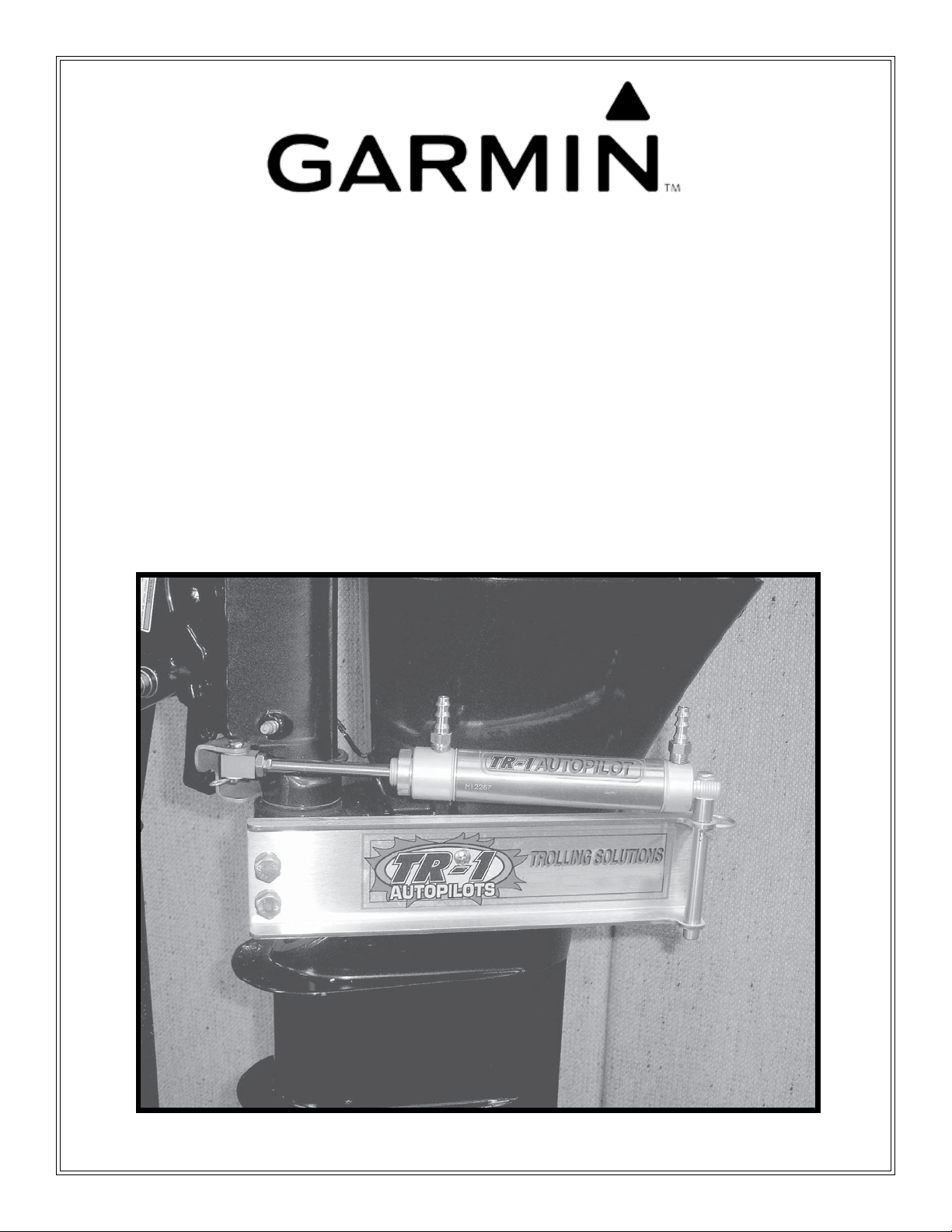
TR-1 Gold
Cylinder and Bracket
Mounting Instructions
Suzuki 9.9 & 15 HP: 1997 & Newer
Johnson/OMC 9.9 & 15 HP: 2002-2007
1
PN 906-1090-00
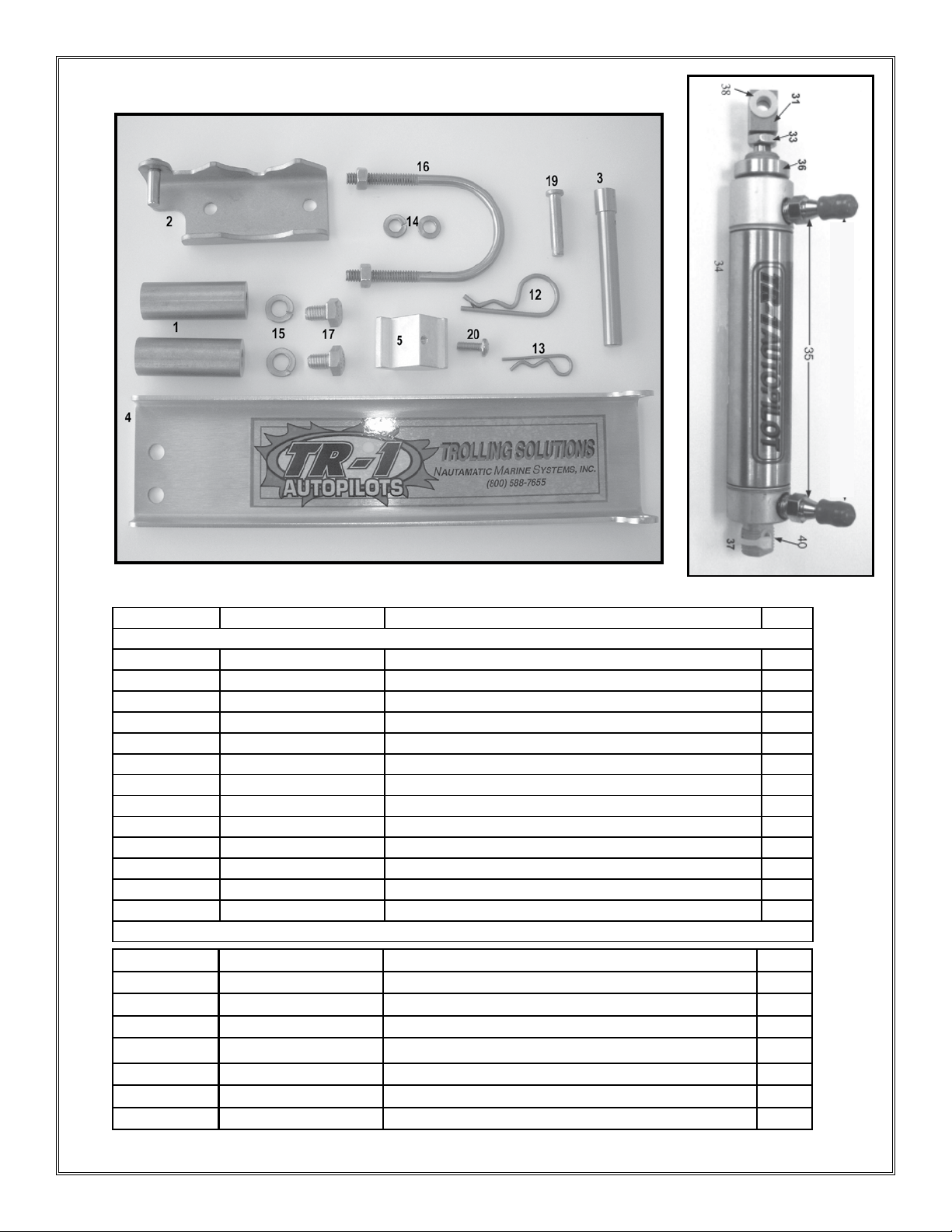
Parts List:
Cylinder Mounting Kit PN 120-1090-00
Cylinder Kit PN 120-0900-00
Item Number Part Number Name Qty.
Cylinder Mounting Kit 120-1090-00
1 330-1091-00 Standoff, Spacer 2
2 130-1092-00 Bracket, Rod Eye Mounting 1
3 330-1023-00 Pin, Stern Pivot 1
4 380-1094-00 Channel, Cylinder Mounting 1
5 340-1095-00 Clamp, Channel Snubber 1
12 310-0067-01 Hair Pin Cotter Lg. 1
13 310-0067-02 Hair Pin Cotter Med. 1
14 310-0076-25 LW, Split 1/4, SS 2
15 310-0076-31 LW,Split 8mm 2
16 130-0084-02 “U” Bolt 1 3/4” ID 1/4-20 with nuts 1
17 310-0208-12 Hex Cap screw M8 X 12mm (bolt) 2
19 310-2501-25 Clevis Pin 1/4 D X 1.25 1
20 310-0014-08 #10-32 UNF X 1/2 Phillips Pan HD screw 1
Cylinder Kit 120-0900-00
31 330-1002-00 Rod Eye, 5/16-24 1
33 310-0042-09 Hex Jam Nut 5/16-24 1
34 340-0900-00 Cylinder 1
35 321-0001-00 Fitting, Straight 1/8 NPT X 1/4 2
36 330-1101-00 Zinc Anode (Replace) 1
37 310-0040-26 Washer, Flat, Nylon 1/4 ID X 3/8 OD x .03 Thick 1
38 328-0901-00 Bushing 1/4 ID X 5/16 OD X 1/4”L 2
40 328-0902-00 Cylinder Tail Bushing 1
2 of 11

Tools:
Minimum Tools Needed:
1- 13 mm Wrench
1- 12mm Wrench
1-1/2 Wrench
1- 7/16 Wrench
1- #1 Phillips Screwdriver
1- Thread Locker (Loctite or similar)
3 of 11
Introduction:
Caution: You are mounting this steering cylinder to a vibration isolation mount on
your motor. Note; that the factory bolts and screws have had thread locker used on
them. You must use thread locker on all threaded nuts and bolts in this installation.
Before starting installation: Loosen the friction lock on the motor. The motor must turn
freely both ways without friction, failure to do so, will cause damage to the autopilot. (It
is located on the Port side of the steering pivot tube.)
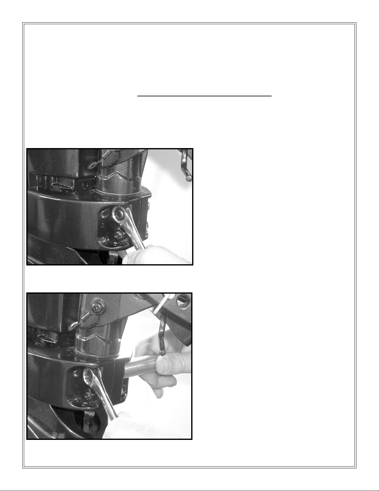
Installation of Mounting Bracket:
Step One:
Remove the upper factory nut and washer from
the lower vibration isolation shroud. See Fig 1
(Save these or use if you change motors)
Fig. 1
Fig. 2
Step Two:
Reverse the factory bolt with it’s washer in the
hole it was removed from. Use thread lock on the
bolt thread and screw it into the stand off spacer
(item #1) and tighten. See Fig 2.
4 of 11
 Loading...