

Garmin TR-1 Gladiator Marine Autopilot User Manual
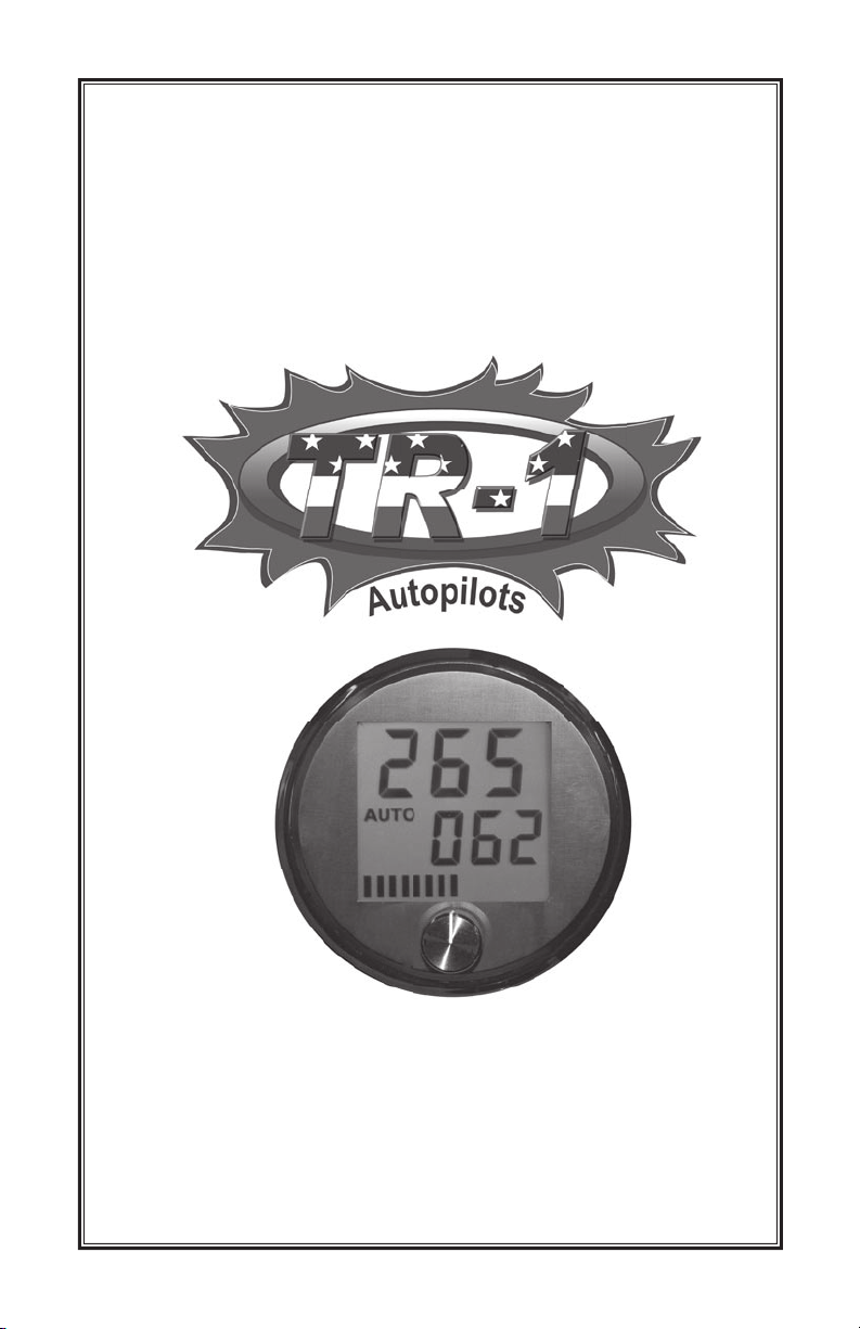
TR-1 Gladiator
LCD Heading Display
Installation & Operations
Owner’s Manual
1-800-588-7655
www.nautamatic.com
906-2700-00
Version 03
TR-1 Gladiator LCD Heading Display
Installation and User Guide
T
hank you for purchasing the TR-1 Gladiator Display. This guide
contains an explanation on how to install and use your new TR-1 Display.
Please be sure to read this instruction manual fully to
yourself with the features and proper installation and operation of
this display.
familiarize
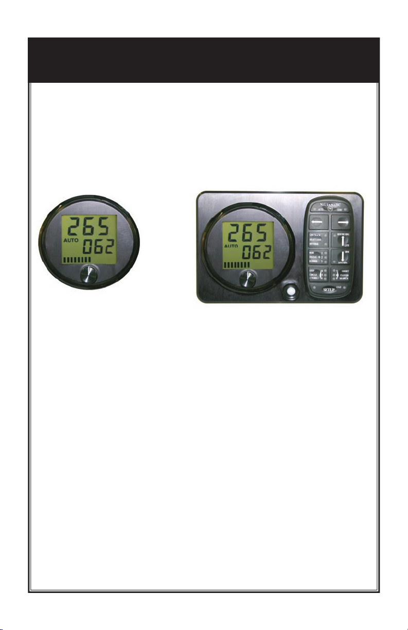
Figure 1-a
Introduction:
The TR-1 LCD display connects to the TR-1 Gladiator Autopilot. It
displays current heading, and displays the current autopilot mode. In
addition it allows the operator to command a new desired heading or
command a rate of turn. With an optional rudder reference indicator;
purchased separately, the display will show rudder position.
The large easy to read trans ective static LCD display with an antire ective coating gives you a clear view of the screen from any
angle on the boat or in glaring sunlight and is backlit for easy night
vision.
An optional mounting panel is available. See Figure 2-a. This panel
will allow you to ush mount a handheld, and mount the deckmount
On/Off switch, in addition to the LCD Display.
Page 1
Figure 2-a

Safety
You are responsible for the safe and prudent operation of
your vessel. Your TR-1 Autopilot is a tool that will enhance
your capability to operate your boat and catch sh. It does
not relieve you from the responsibility for safe operation
of your vessel. You must avoid hazards to navigation and
never leave the helm unattended.
• You must always be prepared to promptly regain manual control of your
boat. The autopilot can fail and hard over.
• Learn to operate your autopilot on calm and hazard free open water.
• In case the autopilot becomes inoperable, remove the in line fuse from the
battery power cable.
• If available, always use the engine kill lanyard when operating your boat.
• Use caution when operating the autopilot at high speeds near hazards in the water, such as docks,
pilings or other boats.
Before Starting Installation
Study this manual and the other manuals provided with your autopilot
carefully, and familiarize yourself with all of the components and
their intended or required mounting locations. Ensure there is
adequate space available for installation before cutting or drilling
holes. Take extreme care when cutting and drilling, to avoid the
possibility of damaging other components in the boat, and avoid
possible personal injury. Be sure to follow the instructions carefully
and thoroughly. Nautamatic Marine Systems, Inc. cannot accept
reasonability for installations where the instructions have not been
followed, where substitute parts have been used, or modications
have been made to our products.
Page 2

Installation of Basic LCD Display
Installation Overview:
• Figure out where on your dash you want to mount the display, or
optional mounting panel. Be sure to allow plenty of room in the
back of the display for mounting accessibility.
• You will need good visibility and convenient reach of the
display.
• Cut a 3-3/4” hole in the desired location.
• Mount the display using the mounting hardware provided.
• Make the proper wire connections to the ECU, the Handheld and
to the rudder reference indicator (optional).
• Turn the Gladiator autopilot system on with the deckmount
On/Off switch and verify display connections. The display should
momentarily light up all functions of the display, then show all
OOO’s across the heading display and STBY will blink for 30
seconds and then display STBY as the mode selection.
• If the Rudder Position Indicator Transducer is used, it must be
installed and calibrated before this mode will work correctly. See
pages 11 & 12 of this manual.
Tools required:
Electric Drill
3.725 dia. hole saw
5/16” open end wrench
Safety Glasses
Additional tools for Mounting Optional Panel:
File for making additional clearances
.75 dia. hole saw
.156 or 5/32” drill bit
Page 3
 Loading...