

Garmin TR-1 Owner's Manual

TR-1
Autopilots
G L A D I A T O R
Owner’s Manual
1
3
Safety
You are responsible for the safe and prudent operation
of your vessel. Your TR-1 Autopilot is a tool that will
enhance your capability to operate your boat and catch
sh. It does not relieve you from the responsibility for
safe operation of your vessel. You must avoid hazards to
navigation and never leave the helm unattended.
Before starting the hydraulic installation, please verify the type of hydraulic steering
in the boat. If it does not match the hydraulic layouts in this manual, please contact
technical support
Hynautic, Latham
NOTE:
for specic installation procedures. Examples: Capilano,
Before proceeding with the installation and operation of the autopilot, read these instructions
thoroughly. TR-1 Autopilots cannot accept responsibility for installations where instructions
have not been followed, where substitute parts have been used, or where modications have
been made to our products. For technical support please call, 1-866-559-0229.
1
2
Table of Contents
Chapter I User Guide
Introduction to operation and adjustments................................................................. 4
System functions and features ................................................................................... 4
Operating the system.................................................................................................. 5
Power On/Off (Deckmount Switch)........................................................................... 6
Illuminate keypad of the remote (Backlight).................
Engaging the autopilot in heading hold...................................................................... 6
Change heading with rudder function..........................................................
Making a turn while in Autopilot.................................................................
Shadow Drive............................................................................................................. 8
Warning Horn............................................................................................................. 8
Go to stored heading...............................................................................
Reverse....................................................................................................................... 8
Selecting patterns..............................................................
Change heading using Man Overboard.................................................................... 10
Change heading using Zigzags....................................
Change heading using Step Turns............................
Change heading with circles..................................................
Change heading with U-Turns.............................
GPS Steering patterns..................................
Course over ground.................................................................................................. 16
Steer to waypoints.................................................................................................... 16
Orbit a waypoint....................................................................................................... 16
Cloverleaf pattern..................................................................................................... 17
Search pattern........................................................................................................... 18
How to change settings using the table of setup codes........
Table of setup codes and the values of the parameters......
..........................
.............................
.........................................
.............................................
................................................
.................................. 13
...................................................
........................
............................
................................
...............
...............
..............
....................
.......
........ 19
. 20- 22
. 14
..
6
6
8
9
11
12
15
7
Chapter II Autopilot Setup
Dockside setup and sea trial setup of autopilot...
Compass calibration............
Autotune............................
Set North..........................................
Trouble shooting guide............................................................................................. 30
Electrical layout........................................................................................................ 31
NMEA 0183 connections.......................................
Non-compliant NMEA 0183 devices........
Warranty Statement .................................................
.........................................................................
.............................
...........................................................
.............................................
.....................................
............................................
............................................................
.............................................
3
..... 24-25
........ 26-27
.....
............ 27-29
................ 29
...... 32
... 33
.. 34

5
Chapter I
........................
User Guide
4
Introduction to Operation and Adjustments
This section of this manual provides you with information of the TR-1 Gladiator autopilots’ capabilities.
We have made every effort to minimize the pain in getting you up to speed as a user of the TR-1, however,
programmable devices such as your TR-1, are often difcult to learn to use and to program. We recommend
that you do not take your shing tackle on your rst trip with your new autopilot. Take a few hours on a nice
day to get your system setup and familiarize yourself with its operation, then your rst shing trip with the unit
will really have you smiling.
This manual is laid out in sections that are, as best we can make them, self contained. We start with the features
and functions available and fundamentals of how the system works, then how to operate the basic functions, and
nally how to get into the ne adjustments.
System Functions and Features
The TR-1 is a heading hold autopilot. It steers to maintain a constant magnetic heading. The autopilot
measures magnetic heading with a uxgate compass and receives rate of turn information from an angular rate
sensor (gyroscope). The autopilot computer forms a rudder rate command from a combination of the compass,
gyro, and engine tachometer signals. This rudder rate command is calculated and sent to the pump controller in
the electrohydraulic unit electronics 20 times each second. The pump controller servos the pumping speed and
direction to match the rudder rate command from the autopilot.
Beyond the basic heading hold function, the autopilot provides for several other modes of automatic and
manually controlled steering functions. These are listed below.
1. Rudder. Rudder steering is used for electrically steering without feedback from the gyro or compass. The
rudder moves while a turn button is held down, and stays in place when the button is let up. (Steering the boat
with the handheld without heading hold.)
2. Rudder command / Attitude hold (RCAH). (Steering the boat with the Handheld while in Autopilot)
RCAH is the primary means for changing the boats’ heading with the remote.
3. Man Overboard. See page10. The autopilot will execute a turn to the reciprocal course and pass near the
maneuver initiation point.
4. Zigzags. See page 11. The autopilot will steer a zigzag course with preset amplitude and period. Factory
Default is set an amplitude (turn) of 30 degrees, and the period (length) set at 1.5 minutes.
5. Step turns. See page 12. The autopilot will execute predetermined xed angle turns in this mode. (Factory
Default is 15 degree turns)
6. Circles. See page 13. The autopilot will turn in continuous circles of preset lap time. (Factory Default is set
at a 5 minute circle.)
7. U-Turns. See page 14. The autopilot will execute a U-Turn by using the right or left chevron buttons on the
handheld
5
7
7. GPS steering.
7a. The autopilot will steer to a waypoint or series of waypoints.
7b. The autopilot will orbit a waypoint.
7c. The autopilot will steer a Cloverleaf pattern over a waypoint.
7d. The autopilot will steer a spiral search pattern around a waypoint.
7e. The autopilot will steer to constant course over ground.
8. Shadow Drive. The autopilot relinquishes control of the autopilot when the helm is turned and then
automatically takes over and steers when the boat is on a constant heading and there is no helm motion.
9. Reverse. The autopilot will attempt to execute many of the above steering functions while the boat is
backing.
10. Return to Selected Heading. The autopilot will drive the boat to a previously stored heading.
11. U-Turn. The autopilot will execute a U-Turn; to port or starboard, depending on which button is pressed.
OPERATING THE SYSTEM
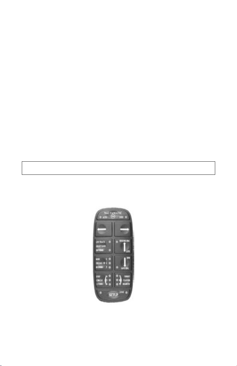
The autopilot is controlled with the handheld/remote, the helm and the deckmount switch. To make
things easy to talk about we will name the buttons as shown in the picture of the remote below.
Auto/Stby Button
Left Arrow Button
GPS Button
Plus Button
Left Chevron Button
Setup Button
Right Arrow Button
Up Arrow Button
Down Arrow Button
Right Chevron Button
Most of the buttons in the system have multiple functions, and many functions are executed by button push
sequences or by pushing more than one button at a time.
6
LED will blink for about 30 seconds
Power On/Off (Deckmount Switch)
Turn power on by pressing and releasing the [Deckmount] switch. Turn the power off by pressing and holding
the switch down until the [Deckmount] switch light has extinguished (about three seconds).
Power on is indicated by illumination of the [Deckmount] switch button and one or more
LED’s lit on the Hand Held.
Both the [Deckmount] button light and remote [STBY]
after turning power on. During this 30-second time, the pilot computers are running self
test and starting up the compass and gyroscope. Autopilot steering is not available during this start up period.
While the system is in standby mode, the STBY LED will light solid on and the deckmount light will brie y
turn off once a second (occulting at 1 Hz).
Illuminate Keypad on Remote
To illuminate keypad on the remote for nighttime operation:
Press and hold [Setup] and press and release the [Up Arrow].
Repeat to turn the back light off. The down arrow will toggle the
brightness of the orange LED’s between bright and dim when the setup is held down.
Engaging the Autopilot In Heading Hold
The [Auto/Stby] button engages and disengages autopilot steering. The
[Deckmount] button performs the same function after the pilot is powered up.
When the button is pressed and released to go into Auto mode, the pilot captures the compass heading and
subsequently moves the rudder to hold that heading. The LED next to “Auto” will illuminate and the deckmount
light will be lit solid on. You should be steering your boat on a constant heading at the time you press the [Auto/
Stby] button.
Change Heading with Rudder Function
The rudder (steering) is directly controlled by [Right Arrow] and [Left Arrow] buttons
when the Rudder LED is illuminated. When you program the [Plus (+)] button for
Rudder, the system will toggle between Rudder mode and heading hold mode when you
press and release the [Plus (+)] button. (Autopilot or heading hold are not available
while you are in Rudder function.)
7
9
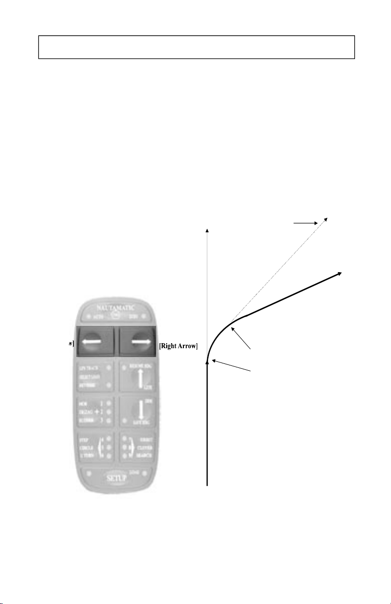
You can steer to a new heading with the Straight Right Arrow and Straight Left Arrow
buttons. Momentary presses of either of these buttons will cause the pilot to alter the heading by
one degree per press. For example, pressing the Straight Left Arrow button five times will
cause the heading to be changed by 5 degrees to the port. Holding either of these buttons down
causes the pilot to turn the rudder so as to make a port or starboard turn. The rudder turns as
long as the button is held down or until the rudder reaches the end of its travel range. When you
release the button, the autopilot will move the rudder to stop the boat from turning. When the
turn is stopped, the autopilot captures the compass heading and then moves the rudder so as to
maintain this heading. An example RCAH turn is shown in the figure below.
Change Heading with RCAH
Initial heading
Final heading
Heading when starboard
RCAH button released
Starboard RCAH button released
Starboard RCAH button pressed
Boat path
Making A Turn While In Autopilot
RCAH (Rudder Command Attitude Hold)
You can steer to a new heading with the [Right Arrow] and [Left Arrow] buttons. See Fig. 1 .The pilot will
alter the heading by one degree per momentary press of either of these buttons. For example, pressing the
[Left Arrow] button ve times will cause the heading to be changed by 5 degrees to the port. Holding either of
these buttons down causes the pilot to turn the rudder so as to make a port or starboard turn. The rudder turns
as long as the button is held down or until the rudder reaches the end of its travel range or the boat is turning
at it’s acceleration limit. When you release the button, the autopilot will move the rudder to stop the boat from
turning. When the turn is stopped, the autopilot captures the compass heading and then moves the rudder so as
to maintain this heading. An example of RCAH turn is shown in the gure 2 below.
Fig.1
8
Fig.2
Shadow Drive ™
When the Shadow Drive feature of the autopilot is enabled, the helm acts as an autopilot dis-engage switch. If
the autopilot is steering the boat, it will surrender control to the helm when the helm is moved. The autopilot
will automatically re-engage when the boat is on a constant heading and there is no helm movement.
Warning Horn
The System sounds a warning horn on the following events:
1. When the rudder is hard against a stop (Double Beep).
2. When the compass is suspect. This may happen when the boat rate of turn exceeds the gyroscope’s
measurement range. It is most likely to happen when the boat is making high speed turns in rough water. The
autopilot will not hold heading for several minutes after such an event (1 solid 3 second beep).
3. When the GPS sends a warning to the autopilot that the navigation data is not reliable. Press any key on the
remote to silence the horn (Continuous beep).
4. When GPS Navigation is terminated by Shadow Drive (1 Single Short Beep).
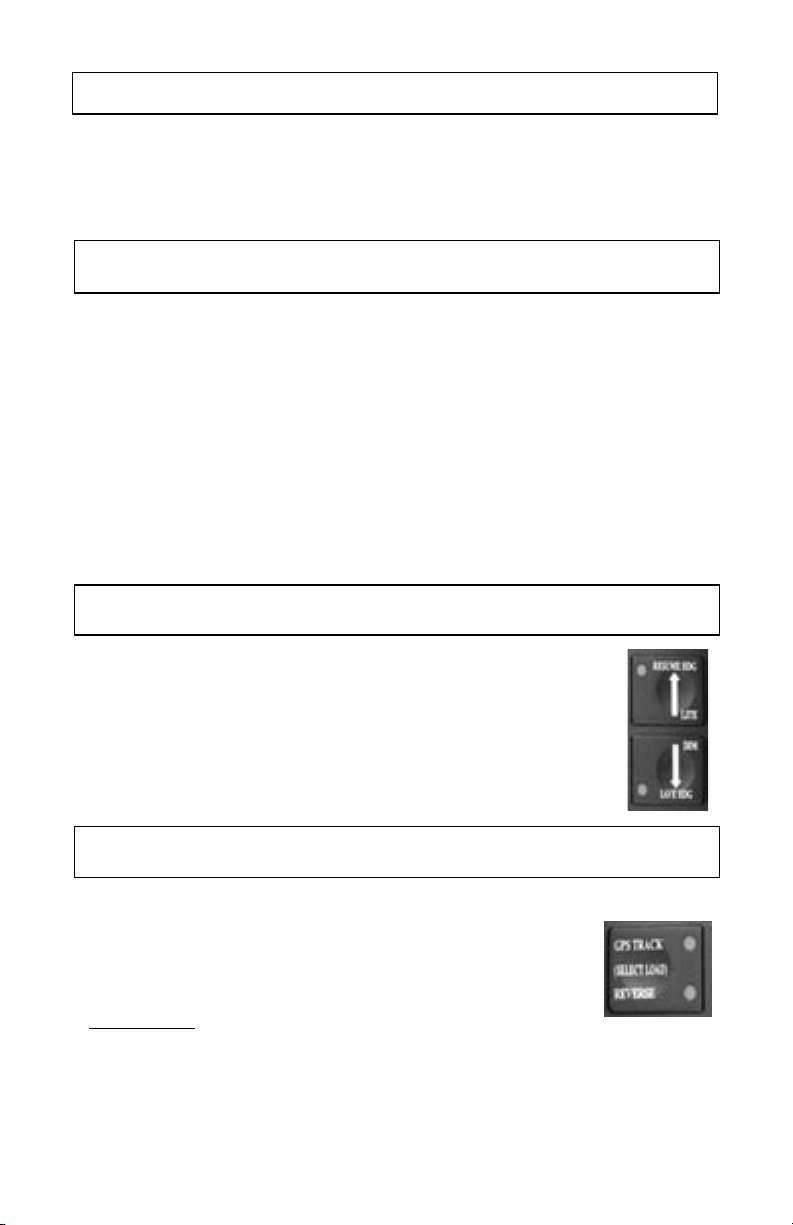
Go to Stored Heading
If you press and release the Down Arrow button while the autopilot is in heading hold
mode, the heading at the instant the button is pressed becomes the stored heading.
Subsequently, while you are in heading hold (at any heading), pressing and releasing
the Up Arrow button will cause the autopilot to steer to the stored heading.
Reverse
The autopilot will attempt to perform any of its steering functions when the boat
is backing in reverse gear. To engage the system in reverse:
1) Start from [Standby]
2) Press and hold the GPS [Rev] button
3) Press and release
4) Release the GPS [Rev] button
the [Auto/Standby] button
9
11
When you select special functions, by the methods described below, you are simply choosing
which function is to be executed by the pilot when you push one of the three special function
buttons.
The Plus button is programmable to provide either MOB, ZigZags, or Rudder. The Left
Chevron button is programmable to provide either Steps, Circles, or U Turns. The Right
Chevron button is programmable to provide Waypoint Orbiting, Clover Leaf, or Search steering
in conjunction with your GPS.
To change the functions of these programmable buttons, follow the directions below.
1. Autopilot must be in Heading Hold or Standby Mode before selection process can start.
(AUTO LED solid on or STBY LED solid on. No other LED's on.)
2. Press and hold
the Setup button. Three LED's next to the numbers 1 through 9 will
illuminate, indicating which (3) special functions are programmed to operate. For example, if
LED's 1, 4, and 7 illuminate, your system is programmed to do: 1) MOB when the Plus button is
pressed. 2) Step Turns to port when the Left Chevron button is pressed. 3) Step Turns to
starboard when the Right Chevron button is pressed. 4) Orbit a waypoint clockwise when the
Right Chevron button is pressed and the system is tracking a GPS signal. 5) Orbit a waypoint
counterclockwise when the Left Chevron button is pressed and the system is tracking a GPS
signal.
3. Select the Special Function you want to use by pressing and releasing the Plus and/or
Chevron buttons until the appropriate LED's are lit. See Special Function Indicators LED
Numbers tables below.
4. Release the Setup Button.
If you press and release the Down Arrow button while the autopilot is in heading hold mode,
the heading at the instant the button is pressed becomes the stored heading. Subsequently, while
you are in heading hold (at any heading), pressing and releasing the Up Arrow button will cause
the autopilot to steer to the stored heading.
5. To make the selected Special Functions into start up defaults: Press and release the Setup
button (the setup LED should be lit), then press and hold
the GPS (Select Load) button, verify
that the Load LED is lit, and then press and release the DM button, then release the GPS
(Select Load)button
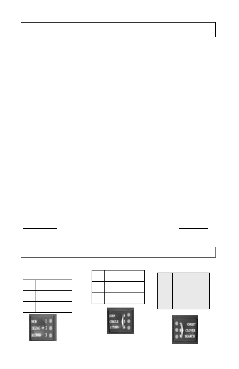
1 MOB 4 Steps
7
Orbit
2 ZigZag 5 Circles
8
3 Leaf Clover
3 Rudder 6 U Turn
9
Search
SPECIAL FUNCTION INDICATOR LED NUMBERS
Selecting Patterns
the GPS (Select Load) button, verify
7
Orbit
8
3 Leaf Clover
9
Search
When you select special functions, by the methods described below, you are simply choosing which
function is to be executed by the pilot when you push one of the three special function buttons below.
The [Plus (+) ] button is programmable to provide either MOB, Zig Zags, or Rudder. The [Left
Chevron] button is programmable to provide either Steps, Circles, or U-Turns. The [Right Chevron]
button is programmable to provide Waypoint Orbiting, Clover Leaf, or Search Steering in conjunction
with your GPS.
To change the functions of these programmable buttons, follow the directions below.
1. Autopilot must be in Heading Hold or Standby Mode before selection process can start. (Auto LED
solid on or STBY LED solid on. No other LED’s on.)
2. Press and hold the [Setup] button. Three LED’s next to the numbers 1 through 9 will illuminate,
indicating which (3) special functions are programmed to do, the factory defaults are: 1) MOB when
the [Plus (+)] button is pressed. 2) Step Turns to port when the [Left Chevron] button is pressed. 3)
Step Turns to starboard when the [Right Chevron] button is pressed. 4) Orbit a waypoint clockwise
when the [Right Chevron] button is pressed and the system is tracking a GPS signal. 5) Orbit a
waypoint counterclockwise when the [Left Chevron] button is pressed and the system is tracking a
GPS signal.
3. Select the Special Function you want to use by pressing and releasing the [Plus (+)] and/or Chevron
buttons until the appropriate LED’s are lit. See Special Function Indicators LED Numbers tables
below.
4. Release the [Setup] button.
5.
To make the selected Functions into startup defaults
Press and release
the [Select Load] button. While holding down the [Select Load] button, press and release the
[Deckmount] On/Off button quickly, then release the GPS [Select Load] button.
the [Setup] button (the [Setup] LED should be lit), and then press and hold
(save the changes into permanent memory)
Pattern Indicator LED Numbers
Following the directions above, you will be able to access all of the Special Pattern Functions
listed below on your handheld.
7 Orbits
8 Clover Leaf
9 Search
:
10
Changing Heading With MOB
Reverse
Circles
Step Turns
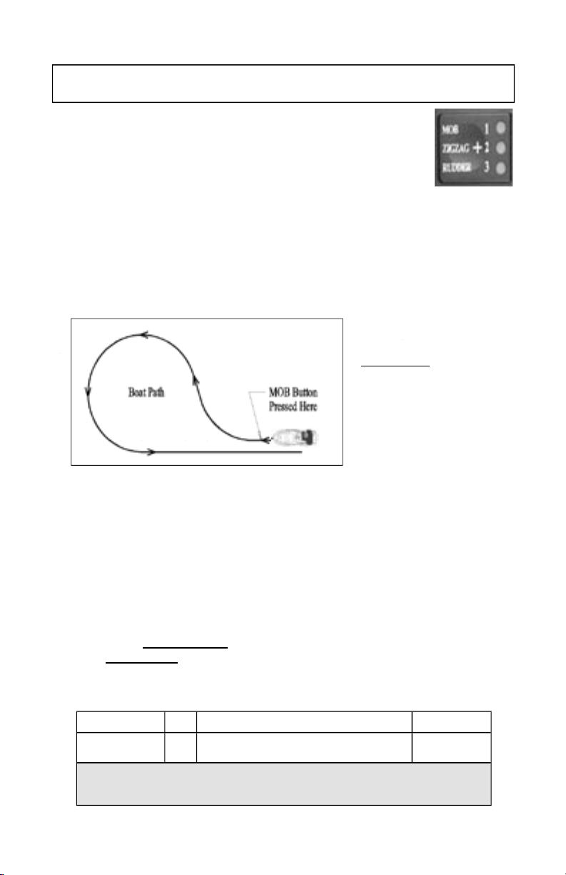
Change Heading Using Man Overboard
The Man Overboard (MOB) function causes the boat to turn to port until the reciprocal
course is established, with the goal of running alongside the point where the Plus button
was pushed, The boat path will be as shown in the gure below. The pilot will return to
heading hold if either of the Right Arrow, Left Arrow, or Plus buttons are pressed.
Code 14: The Man overboard maneuver can be tuned to run close to the object or point
at any given speed, but may miss at another speed. You should probably adjust the maneuver at a speed that is
below planing speed. If the object or point passes on your starboard reduce code 14.
You are responsible as the captain of your boat to use the MOB feature in a manner as to not cause harm to any
person or property. Be aware of any objects in the water before pressing the MOB button. The MOB feature is
not set by GPS. Due to wind, waves and current your boat may not return to the exact reciprocal course when
the MOB button is pressed.
Code and Setup Choice on the table below.)
4. Increase an adjustable parameter one step by each press of the [UP Arrow] button. When the parameter
is adjusted to its maximum value, the [Up Arrow] LED will light. The parameter is adjusted and is in use by
the autopilot immediately.
To change the settings for Man
Overboard:
1. Press and release the [Setup]
Button. The [Setup] LED will
illuminate to indicate the system
is ready to take setup commands
(button pushes).
3. Select and enter code 14 by
pressing and releasing the buttons
labeled 1 & 4 (14) until the
appropriate LED’s are lit. (See the
5. Decrease an adjustable parameter one step by each press of the [Down Arrow] button. When the
parameter is adjusted to its minimum value, the [Down Arrow] LED will light. The parameter is adjusted
and is in use by the autopilot immediately.
6. To save the changes into permanent memory and make the selected function into a
startup default: Press and release the [Setup] button (the [Setup] LED should be lit),
and then press and hold the [Select Load] button. While holding down the [Select Load]
button, press and release the [Deckmount] On/Off button quickly, then release the GPS
[Select Load] button.
Description Code
MOB Overshoot Code
Code 14: The Man overboard maneuver can be tuned to run over or close to the object or point at any given
speed, but may miss at another speed. You should probably adjust the maneuver at a speed that is below
planing speed. If the object or point passes on your starboard reduce code 14.
1 most overshoot command, 40 most under shoot command
14
Range of Settings
11
Factory Setting
10
 Loading...