

G1000 System Maintenance Manual
Diamond DA 40 & DA 40 F
Including GFC 700 or KAP 140 AFCS
Contains FAA-Accepted Instructions
For Continued Airworthiness For
STC SA01444WI-D
190-00545-01 February 2013 Revision G
© Copyright 2008 - 2013
Garmin Ltd. or its subsidiaries
All Rights Reserved
Except as expressly provided herein, no part of this manual may be reproduced, copied, transmitted,
disseminated, downloaded or stored in any storage medium, for any purpose without the express prior
written consent of Garmin. Garmin hereby grants permission to download a single copy of this manual
and of any revision to this manual onto a hard drive or other electronic storage medium to be viewed and
to print one copy of this manual or of any revision hereto, provided that such electronic or printed copy of
this manual or revision must contain the complete text of this copyright notice and provided further that
any unauthorized commercial distribution of this manual or any revision hereto is strictly prohibited.
Garmin International, Inc.
1200 E. 151
st
Street
Olathe, KS 66062 USA
Telephone: 913-397-8200
www.garmin.com
Garmin (Europe) Ltd.
Liberty House
Bulls Copse Road
Hounsdown Business Park
Southampton, SO40 9RB, UK
Phone: +44 (0) 23 8052 4000
Fax: +44 (0) 23 8052 4004
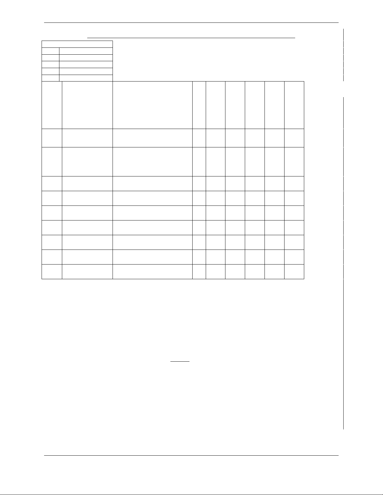
RECORD OF REVISIONS
Revision Revision Date Description ECO #
Update for Phase 7: Add KAP 140 alignment &
B 1/03/2008
update FAR 91.411 & Appendix E testing.
51022
General updates throughout where noted.
C 3/28/2008
D 4/8/2008
E 5/04/09
F 11/12/10
G 2/14/13
Update for minor change to STC
Update for minor change to STC to add software
0321.19.
Update for major change to STC to add software
0321.22
Add Clarification to fuel probe re-calibration
procedures.
Update for major change to STC to add software
0321.23 and hardware upgrades.
52069
52347
58693
76686
99113
DOCUMENT PAGINATION
Section Pagination
Table of Contents i –viii
Section 1 1-1 –1-16
Section 2 2-1 –2-18
Section 3 3-1 –3-48
Section 4 4-1 –4-40
Section 5 5-1 –5-62
Section 6 6-1 –6-16
Section 7 7-1 –7-44
Section 8 8-1 –8-14
Page A G1000 System Maintenance Manual – DA 40/40F
Revision G 190-00545-01

The following are General Safety Precautions that are not related to any specific procedure and therefore
do not appear elsewhere in this maintenance manual. These are recommended precautions that personnel
should understand and apply during the many phases of maintenance and repair.
KEEP AWAY FROM LIVE CIRCUITS. Maintenance personnel shall observe all safety regulations
at all times. Turn off system power before making or breaking electrical connections. Regard any exposed
connector, terminal board, or circuit board as a possible shock hazard. Components which retain a charge
shall be discharged only when such grounding does not result in equipment damage. If a test connection
to energized equipment is required, make the test equipment ground connection before probing the
voltage or signal to be tested.
INFORMATION SUBJECT TO EXPORT CONTROL LAWS
This document may contain information which is subject to the Export Administration Regulations
("EAR") issued by the United States Department of Commerce (15 CFR, Chapter VII, Subchapter C) and
which may not be exported, released, or disclosed to foreign nationals inside or outside of the United
States without first obtaining an export license. A violation of the EAR may be subject to a penalty of up
to 10 years imprisonment and a fine of up to $1,000,000 under Section 2410 of the Export Administration
Act of 1979. Include this notice with any reproduced portion of this document.
WARNING!
This product, its packaging, and its components contain chemicals known to the State of California to
cause cancer, birth defects, or reproductive harm. This Notice is being provided in accordance with
California's Proposition 65. If you have any questions or would like additional information, please refer
to our web site at www.garmin.com/prop65
.
WARNING!
The GDU 104X lamps contain mercury and must be recycled or disposed of according to local, state, or
federal laws. If you have any questions or would like additional information, please refer to our web site
at www.garmin.com/aboutGarmin/environment/disposal.jsp.
CAUTION
The GDU 1040s use a lens coated with a special anti-reflective coating that is very sensitive to skin oils,
waxes and abrasive cleaners. CLEANERS CONTAINING AMMONIA WILL HARM THE ANTIREFLECTIVE COATING. It is very important to clean the lens using a clean, lint-free cloth and an
eyeglass lens cleaner that is specified as safe for anti-reflective coatings.
NOTE
All G1000 screen shots used in this document are current at the time of publication. Screen shots are
intended to provide visual reference only. All information depicted in screen shots, including software
file names, versions and part numbers, is subject to change and may not be up to date.
NOTE
The LRU serial numbers displayed on the screen are for convenience only and should be disregarded in
determining the LRU software revision. For compliance activities requiring LRU serial number
determination, the unit serial number used must be that on the physical LRU label, not the one displayed
on the SYSTEM STATUS page.
NOTE
All references to Diamond DA 40 aircraft made in this manual equally apply to Diamond DA 40 F
aircraft, unless otherwise noted.
NOTE
All references to GIA 63 LRUs made in this manual equally apply to GIA 63W LRUs unless otherwise
noted.
G1000 System Maintenance Manual – Diamond DA40/40F Page i
190-00545-01 Revision G

TABLE OF CONTENTS
PARAGRAPH PAGE
1 INTRODUCTION 1-1
1.1 C
1.2 O
1.3 D
1.4 P
1.5 D
1.6 R
ONTENT, SCOPE, PURPOSE .......................................................................................................... 1-1
RGANIZATION ............................................................................................................................. 1-9
EFINITIONS/ABBREVIATIONS .................................................................................................... 1-10
UBLICATIONS ............................................................................................................................ 1-12
ISTRIBUTION ............................................................................................................................. 1-14
EQUIRED MATERIALS & EQUIPMENT ....................................................................................... 1-14
2 SYSTEM DESCRIPTION 2-1
2.1 STC
2.2 E
2.3 G1000
2.4 GFC
2.5 E
2.6 L
2.7 S
2.8 S
2.9 B
REQUIREMENTS OVERVIEW .................................................................................................. 2-1
QUIPMENT DESCRIPTIONS ........................................................................................................... 2-2
OPTIONAL INTERFACES ..................................................................................................... 2-5
700 AFCS SYSTEM DESCRIPTION ........................................................................................ 2-7
LECTRICAL POWER DISTRIBUTION ........................................................................................... 2-13
IGHTNING STRIKE PROTECTION ................................................................................................ 2-16
HIELD BLOCK GROUNDS ........................................................................................................... 2-17
ENSOR INSTALLATIONS ............................................................................................................. 2-17
LOCK DIAGRAMS ...................................................................................................................... 2-17
3 G1000 CONTROL & OPERATION 3-1
3.2 G1000
3.3 G1000
3.4 G1000
3.5 G1000
OPERATION MODES ........................................................................................................... 3-3
CONFIGURATION MODE OVERVIEW .................................................................................. 3-5
/ GFC 700 SOFTWARE INFORMATION .............................................................................. 3-14
SOFTWARE/CONFIGURATION PROCEDURE ...................................................................... 3-23
4 INSTRUCTIONS FOR CONTINUED AIRWORTHINESS 4-1
4.1 A
4.2 S
4.3 M
4.4 V
4.5 E
4.6 F
4.7 GRS
4.8 GSA
4.9 F
4.10 S
4.11 PFD/MFD
4.12 L
4.13 C
IRWORTHINESS LIMITATIONS ..................................................................................................... 4-1
ERVICING INFORMATION ............................................................................................................. 4-2
AINTENANCE INTERVALS ........................................................................................................... 4-4
ISUAL INSPECTION ...................................................................................................................... 4-8
LECTRICAL BONDING TEST ....................................................................................................... 4-11
UEL TANK PROBE RE-CALIBRATION ........................................................................................ 4-13
77 EARTH MAGNETIC FIELD UPDATES ............................................................................... 4-21
81 GREASING PROCEDURE ................................................................................................. 4-21
LAP POSITION DISCRETE INPUT CHECK .................................................................................... 4-22
LIP CLUTCH TORQUE CHECK PROCEDURES .............................................................................. 4-24
POWER INTERRUPT FUNCTION CHECKS .................................................................... 4-30
IGHTNING PROTECTION FUSE REPLACEMENT .......................................................................... 4-35
OOLING FAN FUNCTION & FAN FAIL ANNUNCIATION TEST .................................................... 4-39
5 TROUBLESHOOTING 5-1
5.1 G1000
5.2 S
5.3 DA
5.4 TAWS
5.5 GFC
5.6 B
5.7 GDU
5.8 GDU
5.9 GIA
5.10 GIA
ALERTING SYSTEM ............................................................................................................ 5-2
YSTEM ANNUNCIATIONS ............................................................................................................. 5-5
40/DA 40 F SPECIFIC ALERTS .............................................................................................. 5-12
TROUBLESHOOTING ........................................................................................................ 5-14
700 AFCS TROUBLESHOOTING .......................................................................................... 5-15
ACKUP COMMUNICATIONS PATH CHECKS ............................................................................... 5-27
104X TROUBLESHOOTING ................................................................................................. 5-42
104X ALERTS .................................................................................................................... 5-43
63 TROUBLESHOOTING ........................................................................................................ 5-50
ALERT MESSAGES ............................................................................................................... 5-51
Page ii G1000 System Maintenance Manual – Diamond DA40/40F
Revision G 190-00545-01

5.11 GEA
5.12 GTX
5.13 GRS
5.14 GDC
5.15 GDL
5.16 GDL
5.17 GSR
5.18 S
5.19 ESP
TROUBLESHOOTING ........................................................................................................... 5-55
TROUBLESHOOTING ........................................................................................................... 5-55
77/GMU 44 TROUBLESHOOTING ........................................................................................ 5-56
74A TROUBLESHOOTING ................................................................................................... 5-57
69A TROUBLESHOOTING .................................................................................................... 5-58
59 TROUBLESHOOTING ...................................................................................................... 5-59
56 TROUBLESHOOTING ....................................................................................................... 5-60
YNTHETIC VISION AND PATHWAYS TROUBLESHOOTING ......................................................... 5-61
TROUBLESHOOTING ............................................................................................................. 5-62
6 G1000 EQUIPMENT REMOVAL & REPLACEMENT 6-1
6.1 GDU
6.2 GMA
6.3 GIA
6.4 GEA
6.5 GTX
6.6 GTP
6.7 GRS
6.8 GMU
6.9 GDL
6.10 GSA
6.11 GSM
6.12 C
6.13 GEA
6.14 GA35
6.15 GDL
6.16 GSR
6.17 I
6.18 W
104X MFD & PFD ............................................................................................................... 6-4
1347 AUDIO PANEL ............................................................................................................. 6-4
63 (W) INTEGRATED AVIONICS UNITS .................................................................................. 6-4
71 ENGINE/AIRFRAME UNIT ................................................................................................ 6-5
33 TRANSPONDER ................................................................................................................ 6-5
59 OAT PROBE ..................................................................................................................... 6-6
77 AHRS .............................................................................................................................. 6-6
44 MAGNETOMETER ........................................................................................................... 6-7
69A....................................................................................................................................... 6-7
81 SERVOS ............................................................................................................................ 6-7
85 & GSM 86 SERVO MOUNTS ............................................................................................ 6-8
ONFIGURATION MODULE REMOVAL & REPLACEMENT ............................................................. 6-8
71 BACKSHELL THERMOCOUPLE REMOVAL & REPLACEMENT ......................................... 6-11
GPS/WAAS ANTENNAS ................................................................................................... 6-12
59 DATALINK ..................................................................................................................... 6-12
56 SATELLITE RECEIVER .................................................................................................... 6-12
RIDIUM ANTENNA (OPTIONAL) .................................................................................................. 6-13
I-FI ANTENNA (OPTIONAL) ..................................................................................................... 6-13
7 G1000 EQUIPMENT CONFIGURATION & TESTING 7-1
7.1 GDU
7.2 GMA
7.3 GIA
7.4 GEA
7.5 GTX
7.6 GDC
7.7 GRS
7.8 GDL
7.9 GDL
7.10 GSR
7.11 GSA
104X MFD & PFD ............................................................................................................... 7-3
1347 AUDIO PANEL ............................................................................................................. 7-7
63 INTEGRATED AVIONICS UNIT ......................................................................................... 7-10
71 ENGINE/AIRFRAME UNIT .............................................................................................. 7-16
33 TRANSPONDER .............................................................................................................. 7-19
74A AIR DATA COMPUTER ................................................................................................ 7-21
77 AHRS / GMU 44 MAGNETOMETER ............................................................................... 7-25
69 XM DATA LINK ............................................................................................................. 7-36
59 DATALINK ..................................................................................................................... 7-37
56 ........................................................................................................................................ 7-39
81 SERVO ............................................................................................................................ 7-42
8 SYSTEM RETURN TO SERVICE PROCEDURE 8-1
8.1 S
8.2 B
8.3 GFC
8.4 M
OFTWARE VERIFICATION ............................................................................................................ 8-1
ACKUP PATH SYSTEM TESTING .................................................................................................. 8-2
700 GROUND CHECKOUT.................................................................................................... 8-10
AINTENANCE RECORDS ........................................................................................................... 8-13
G1000 System Maintenance Manual – Diamond DA40/40F Page iii
190-00545-01 Revision G

LIST OF ILLUSTRATIONS
FIGURE PAGE
Figure 2-1. SVS/Pathways Feature ........................................................................................................... 2-6
Figure 2-2. AFCS System Block Diagram ................................................................................................ 2-9
Figure 2-3. GSA 81 & GSM 85 or GSM 86 ........................................................................................... 2-11
Figure 2-4. G1000/DA40 Electrical Distribution (GFC 700 Aircraft) .................................................... 2-14
Figure 2-5. G1000/DA40 Electrical Distribution (KAP140 Aircraft) .................................................... 2-15
Figure 2-6. G1000/KAP 140 Block Diagram (no WAAS) ..................................................................... 2-17
Figure 2-7. G1000/GFC 700 Block Diagram (WAAS shown) ............................................................... 2-18
Figure 3-1. GDU 104X Control Interface (GDU 1042 shown) ................................................................ 3-1
Figure 3-2. AFCS Controls (GDU 1044 shown) ...................................................................................... 3-1
Figure 3-3. GMA 1347 Controls ............................................................................................................... 3-2
Figure 3-4. G1000 Softkeys ...................................................................................................................... 3-3
Figure 3-5. Normal Mode ......................................................................................................................... 3-3
Figure 3-6. MFD Failure Mode................................................................................................................. 3-4
Figure 3-7. PFD Failure Mode .................................................................................................................. 3-4
Figure 3-8. SYSTEM UPLOAD FIELDS (SW v0321.19 or earlier) ....................................................... 3-5
Figure 3-9. SYSTEM UPLOAD FIELDS (SW v0321.22 or later) .......................................................... 3-5
Figure 3-10. SET>ACTV Diagram ........................................................................................................... 3-7
Figure 3-11. Loss of Communication ....................................................................................................... 3-8
Figure 3-12. Configuration Status ............................................................................................................. 3-8
Figure 3-13. Data Transmission Indicators ............................................................................................. 3-10
Figure 3-14. MFD Power Up Splash Screen System Software Version ................................................. 3-14
Figure 3-15. MFD AUX –System Status Page System Software Version.............................................. 3-14
Figure 3-16. Options Configuration Files System Upload Page ............................................................. 3-17
Figure 3-17. Calibration Files System Upload Page ............................................................................... 3-18
Figure 3-18. G1000 LRU Configuration File Storage ............................................................................ 3-21
Figure 3-19. GRS/GDC Configuration Settings Storage ........................................................................ 3-22
Figure 3-20. Software/Configuration Overview ..................................................................................... 3-23
Figure 3-21. Non-WAAS (GIA 63) System Status Page ........................................................................ 3-27
Figure 3-22. WAAS (GIA 63W) System Status Page ............................................................................ 3-28
Figure 3-23. System Upload Page ........................................................................................................... 3-28
Figure 3-24. GIA Boot Block Upload Page ............................................................................................ 3-31
Figure 3-25. GIA Boot Block Upload Complete Page ........................................................................... 3-32
Figure 3-26. System Status Page (SW v0321.19 and earlier) ................................................................. 3-33
Figure 3-27. System Status Page (SW v0321.22 or later) ....................................................................... 3-33
Figure 3-28. System ID Location ............................................................................................................ 3-41
Figure 3-29. System Upload Page ........................................................................................................... 3-43
Figure 3-30. DA40 Splash Screen for Non ESP Configurations ............................................................ 3-45
Figure 3-31. DA40 FP Splash Screen for Non ESP Configurations ....................................................... 3-45
Figure 3-32. DA40 Splash Screen for ESP Configurations .................................................................... 3-46
Figure 3-33. DA40 FP Splash Screen for ESP Configurations ............................................................... 3-46
Figure 4-1. Total Time In Service ............................................................................................................. 4-3
Figure 4-2 Fuel Calibration Page (Calibration Table) ............................................................................. 4-14
Figure 4-3 System Upload Page............................................................................................................... 4-15
Figure 4-4 Fuel Calibration Page ............................................................................................................. 4-17
Figure 4-5 Fuel Calibration Page (Empty Calibration) ............................................................................ 4-18
Figure 4-6 System Upload Page............................................................................................................... 4-18
Figure 4-7 Fuel Calibration Page (5 Gallon Calibration) ......................................................................... 4-19
Figure 4-8 System Upload Page............................................................................................................... 4-20
Figure 4-9 Fuel Calibration Page (Calibration Complete) ....................................................................... 4-20
Figure 4-10. (SW v0321.19 or earlier) GIA I/O Page ............................................................................. 4-22
Page iv G1000 System Maintenance Manual – Diamond DA40/40F
Revision G 190-00545-01

Figure 4-11. (SW v0321.22 or later) GIA I/O Page ................................................................................ 4-23
Figure 4-12, GFC Status Page................................................................................................................. 4-24
Figure 4-13. GDU TEST Page ................................................................................................................ 4-30
Figure 4-14. Backup Capacitor Test Selection ....................................................................................... 4-32
Figure 4-15. Upload Complete Window ................................................................................................. 4-33
Figure 4-16. BKUP CAPS Checkbox on GDU TEST Page ................................................................... 4-34
Figure 4-17. Aircraft Fuselage Fuse Locations ....................................................................................... 4-35
Figure 4-18. Instrument Panel Detail A .................................................................................................. 4-36
Figure 4-19. Instrument Panel Detail B .................................................................................................. 4-36
Figure 4-20. Remote Avionics Enclosure Detail C ................................................................................. 4-37
Figure 4-21. Remote Avionics Enclosure Detail D ................................................................................ 4-38
Figure 5-1. AUX – System Status Page .................................................................................................... 5-1
Figure 5-2. Alerts & Annunciations .......................................................................................................... 5-2
Figure 5-3. WARNING Softkey Annunciation ........................................................................................ 5-3
Figure 5-4. CAUTION Softkey Annunciation .......................................................................................... 5-3
Figure 5-5. ADVISORY Softkey Annunciation ....................................................................................... 5-3
Figure 5-6. System Annunciations ............................................................................................................ 5-5
Figure 5-7. AFCS Annunciation Field .................................................................................................... 5-15
Figure 5-8, GFC Status Page................................................................................................................... 5-18
Figure 5-9. GMA 1347 Data Paths ......................................................................................................... 5-27
Figure 5-10. GEA 71 Data Paths ............................................................................................................ 5-28
Figure 5-11. GTX 33 Data Paths ............................................................................................................ 5-29
Figure 5-12. GDC 74A Data Paths ......................................................................................................... 5-30
Figure 5-13. GRS 77 Data Paths ............................................................................................................. 5-31
Figure 6-1. (SW v0321.19 or earlier) System Status Page (Configuration Mode) .................................. 6-1
Figure 6-2. (SW v0321.22 or later) System Status Page (Configuration Mode) ..................................... 6-2
Figure 6-3. Configuration Module Installation ......................................................................................... 6-9
Figure 6-4. GEA Backshell Thermocouple ............................................................................................. 6-11
Figure 7-1. Non-WAAS (GIA 63) System Status Page ............................................................................ 7-2
Figure 7-2. WAAS (GIA 63W) System Status Page ................................................................................ 7-2
Figure 7-3. G1000 Normal Mode Check ..........................................................................................
........ 7-5
Figure 7-4. G1000 Reversionary Mode Check ......................................................................................... 7-6
Figure 7-5. MFD TAWS Page .................................................................................................................. 7-6
Figure 7-6. Marker Beacon Symbology .................................................................................................... 7-9
Figure 7-7. SET>ACTV Softkey ............................................................................................................ 7-10
Figure 7-8. AUX – GPS STATUS Page (MFD) ..................................................................................... 7-12
Figure 7-9. Engine Instrument Pages ...................................................................................................... 7-17
Figure 7-10. Engine Instrument Sub Pages ............................................................................................. 7-18
Figure 7-11. GTX Configuration Page ................................................................................................... 7-20
Figure 7-12. EASA Airspeed Tape ......................................................................................................... 7-23
Figure 7-13. GRS/GMU Calibration Page .............................................................................................. 7-28
Figure 7-14. GRS/GMU Calibration Page .............................................................................................. 7-30
Figure 7-15. GRS/GMU Calibration Page .............................................................................................. 7-32
Figure 7-16. Magnetometer Interference Test Page ................................................................................ 7-33
Figure 7-17. Normal Mode AHRS Check .............................................................................................. 7-35
Figure 7-18. Reversionary Mode AHRS Information ............................................................................. 7-35
Figure 7-19. GSR 56 Configuration Page for Combination Option ....................................................... 7-38
Figure 7-20. Good Iridium Signal Strength ............................................................................................ 7-38
Figure 7-21. No Iridium Signal Strength ................................................................................................ 7-39
Figure 7-22. GSR 56 Configuration Page for Combination Option ....................................................... 7-40
Figure 7-23. GSR 56 Configuration Page for Standalone Option .......................................................... 7-40
Figure 7-24. Good Iridium Signal Strength ............................................................................................ 7-41
Figure 7-25. No Iridium Signal Strength ................................................................................................ 7-41
G1000 System Maintenance Manual – Diamond DA40/40F Page v
190-00545-01 Revision G

Figure 8-1. PFD RS-232/ARINC 429 Configuration Page ....................................................................... 8-7
Figure 8-2. GIA1 RS-232/ARING 429 Configuration Page ..................................................................... 8-8
Figure 8-3. GIA1 RS-485 Configuration Page ......................................................................................... 8-9
Figure 8-4. Pre-Flight Test ...................................................................................................................... 8-10
Page vi G1000 System Maintenance Manual – Diamond DA40/40F
Revision G 190-00545-01

LIST OF TABLES
TABLE PAGE
Table 1-1. MDL Configurations Summary ............................................................................................... 1-2
Table 1-2. Required Documents ............................................................................................................. 1-12
Table 1-3. Previously Approved Type Design ........................................................................................ 1-13
Table 1-4. Reference Publications .......................................................................................................... 1-13
Table 1-5. Loader Card to Configuration Relationship Summary .......................................................... 1-15
Table 3-1. Data Transmission Indicators .................................................................................................. 3-9
Table 3-2. Page Navigation SW v0321.19 or earlier .............................................................................. 3-11
Table 3-3. Page Navigation SW v0321.22 .............................................................................................. 3-12
Table 3-4. Page Navigation SW v0321.23 .............................................................................................. 3-13
Table 3-5. LRU to Configuration File Relationship Summary ............................................................... 3-19
Table 4-1. Maintenance Intervals .............................................................................................................. 4-4
Table 4-2. Visual Inspection Procedure .................................................................................................... 4-8
Table 4-3. GSM 86 Measured Torque .................................................................................................... 4-28
Table 4-4. Power Interrupt Category A (200mS) Mod Status ................................................................ 4-30
Table 4-5. Power Interrupt Category A (200mS) Mod Status ................................................................ 4-31
Table 4-6. Lightning Protection Fuse Part Numbers .............................................................................. 4-35
Table 5-1. Aural and Audio Alerts ............................................................................................................ 5-4
Table 5-2. System Failure Troubleshooting .............................................................................................. 5-6
Table 5-3. Engine Airframe Instrument Failures .................................................................................... 5-10
Table 5-4. ADF/DME Failure ................................................................................................................. 5-11
Table 5-5. Warning Alerts ...................................................................................................................... 5-12
Table 5-6. Caution Alerts ........................................................................................................................ 5-12
Table 5-7. Message Advisory Alerts (SW v0321.22 and earlier) ........................................................... 5-13
Table 5-8. TAWS Troubleshooting ........................................................................................................ 5-14
Table 5-9. AFCS Annunciation Troubleshooting ................................................................................... 5-16
Table 5-10. AFCS General Troubleshooting .......................................................................................... 5-17
Table 5-11. PFT Faults (Monitor Processor) .......................................................................................... 5-24
Table 5-12. Normal Mode Faults (Monitor Processor) ........................................................................... 5-24
Table 5-13. PFT Faults (Control Processor) ........................................................................................... 5-25
Table 5-14. Normal Mode Faults (Control Processor) ............................................................................ 5-25
Table 5-15. Data Path Failure Troubleshooting ...................................................................................... 5-32
Table 5-16. PFD1 ARINC 429 ............................................................................................................... 5-33
Table 5-17. MFD1 ARINC 429 ...................................................................................................
........... 5-34
Table 5-18. GIA1 RS-232 ....................................................................................................................... 5-35
Table 5-19. GIA1 ARINC 429 ................................................................................................................ 5-37
Table 5-20. GIA2 RS-232 ....................................................................................................................... 5-38
Table 5-21. GIA2 ARINC 429 ................................................................................................................ 5-39
Table 5-22. GIA1 RS-485 ....................................................................................................................... 5-40
Table 5-23. GIA2 RS-485 ....................................................................................................................... 5-41
Table 5-24. GDU 104X Common Problems ........................................................................................... 5-42
Table 5-25. GDU 104X Software/Configuration Alerts ......................................................................... 5-43
Table 5-26. Database Alerts .................................................................................................................... 5-44
Table 5-27. Cooling Alerts ..................................................................................................................... 5-45
Table 5-28. Datacard Alerts .................................................................................................................... 5-46
Table 5-29. Key Alerts ............................................................................................................................ 5-46
Table 5-30. Miscellaneous Alerts ........................................................................................................... 5-47
Table 5-31. GMA Common Problems .................................................................................................... 5-49
Table 5-32. GMA Alerts ......................................................................................................................... 5-49
Table 5-33. COM Troubleshooting ......................................................................................................... 5-50
G1000 System Maintenance Manual – Diamond DA40/40F Page vii
190-00545-01 Revision G

Table 5-34. NAV Troubleshooting ......................................................................................................... 5-50
Table 5-35. GS Troubleshooting ............................................................................................................. 5-50
Table 5-36. GPS Troubleshooting .......................................................................................................... 5-50
Table 5-37. COM Alerts ......................................................................................................................... 5-51
Table 5-38. NAV AlertsFailure Message ............................................................................................... 5-52
Table 5-39. Glideslope Alerts ................................................................................................................. 5-53
Table 5-40. GPS Alerts ........................................................................................................................... 5-53
Table 5-41. GIA Cooling Alerts ............................................................................................................. 5-54
Table 5-42. GIA Configuration Alerts .................................................................................................... 5-54
Table 5-43. GEA Common Problems ..................................................................................................... 5-55
Table 5-44. GEA Alerts .......................................................................................................................... 5-55
Table 5-45. GTX Alerts .......................................................................................................................... 5-55
Table 5-46. AHRS Common Problems ................................................................................................... 5-56
Table 5-47. GRS Alerts ........................................................................................................................... 5-56
Table 5-48. GMU Alerts ......................................................................................................................... 5-57
Table 5-49. Air Data Common Problems ............................................................................................... 5-57
Table 5-50. GDC Alerts .......................................................................................................................... 5-57
Table 5-51. GDL 69A Common Problems ............................................................................................. 5-58
Table 5-52. GDL 69A Alerts .................................................................................................................. 5-59
Table 5-53. GDL 59 Troubleshooting ..................................................................................................... 5-59
Table 5-54. GDL 59 Alerts ..................................................................................................................... 5-59
Table 5-55. GSR 56 Troubleshooting ..................................................................................................... 5-60
Table 5-56. GSR 56 Alerts ...................................................................................................................... 5-60
Table 5-57. SVS Troubleshooting ........................................................................................................... 5-61
Table 5-58. SVS-Related Alert Messages ............................................................................................... 5-61
Table 5-59. ESP Troubleshooting ............................................................................................................ 5-62
Table 5-60. ESP-Related Alert Messages ............................................................................................... 5-62
Table 6-1. Equipment Removal and Replacement Software Check ......................................................... 6-2
Table 6-2. Configuration Module Kit – 011-00979-00 ............................................................................. 6-9
Table 6-3. Thermocouple Kit (011-00981-00) ....................................................................................... 6-11
Table 7-1: Engine/Airframe Instrument Checks ..................................................................................... 7-18
Table 7-2. Airspeed Test ......................................................................................................................... 7-23
Table 7-3. EASA Airspeed Tape Test .................................................................................................... 7-23
Table 7-4. Vertical Speed Test Tolerances ............................................................................................. 7-24
Table 7-5. GRS/GMU Calibration Requirement Matrix ......................................................................... 7-26
Table 7-6. Magnetometer Interference Test Sequence (Example) .......................................................... 7-33
Table 8-1. Return To Service Software Check ......................................................................................... 8-1
Table 8-2. GPS Failure Test ...................................................................................................................... 8-3
Table 8-3. GIA Failure Test ...................................................................................................................... 8-4
Table 8-4. Display Failure Test ................................................................................................................. 8-6
Page viii G1000 System Maintenance Manual – Diamond DA40/40F
Revision G 190-00545-01

1 INTRODUCTION
1.1 Content, Scope, Purpose
This document provides Instructions for Continued Airworthiness (ICA) for the Garmin G1000 integrated
avionics and GFC700 Automatic Flight Control System (AFCS) as installed in the Diamond Model
DA 40 and DA 40 F. This document satisfies the requirements for continued airworthiness as defined by
14 CFR Part 23.1529 and Appendix G. Information in this document is required to maintain the
continued airworthiness of the G1000 and GFC700.
1.1.1 Applicability
This document applies to all Diamond Aircraft Industries, Inc., Model DA 40 and DA 40 F aircraft
equipped with the G1000 and optional GFC700 AFCS system under this STC.
Modification of an aircraft by this Supplemental Type Certificate (STC) obligates the aircraft operator to
include the maintenance information provided by this document in the operator’s Aircraft Maintenance
Manual and the operator’s Aircraft Scheduled Maintenance Program.
This System Maintenance manual and the contained Instructions for Continued Airworthiness supersedes
all previous system maintenance manuals and ICAs, including the following Garmin documents:
• 190-00303-03
• 190-00492-01
• 190-00492-03
• 190-00545-00
NOTE
Differences in software versions that affect the maintenance manual content will be indicated within the
procedures as needed. If no indication of software version is provided for the procedure or step then it is
understood to apply to all software versions.
G1000 System Maintenance Manual – Diamond DA40/40F Page 1-1
190-00545-01 Revision G
1.1.2 Identifying an MDL Configuration
There are six approved configurations within this STC, each defined as a subset of the Master Drawing
List (MDL). Each configuration differs in both hardware and software installation requirements.
Refer to the MDL, Garmin document 005-00400-01 for each configuration type design definition.
Configuration
-1 Configuration
MDL
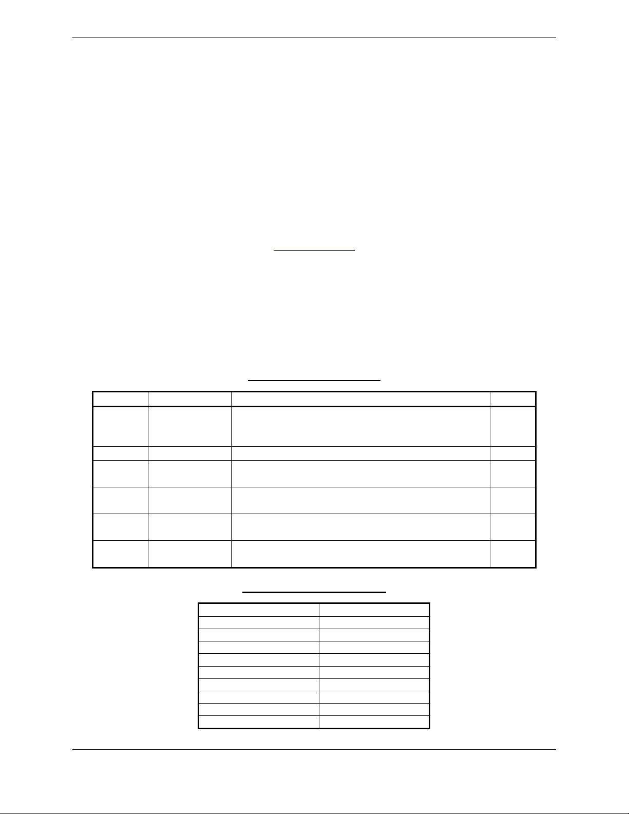
Table 1-1. MDL Configurations Summary
Aircraft
System
G1000 &
GFC 700
with WAAS
Upgrades Available
Major Functions Added
• G1000 & GFC 700 AFCS
• WAAS
• Coupled baro-VNAV
• GDU Charts
• Misc. GDU v8.02 features
Hardware Added
GDU 1044 MFD Optional
GIA 63W Integrated Avionics (qty 2)
GA35 GPS/WAAS antennas (qty 2)
Major Functions Added
• Misc. GDU v8.20 features
Hardware Added
GIA 63W P/N 011-01105-01
GDC 74A P/N 011-00882-10
Major Functions Added
• Misc. GDU v9.01 features
Hardware Added
None
Major Functions Added
• Misc. GDU v9.01 features
(Non WAAS Support)
Hardware Added
None
Major Functions Added
• Import Flt Plans from SD Card
• Temporary Waypoints
• Flight Data Logging to SD Card
• GDL69 Aviator Pro features
• Misc. GDU v9.15 features
Hardware Added
None
G1000 System
Software Version
0369.13
0321.17
0321.18
0321.19
0321.22
Page 1-2 G1000 System Maintenance Manual – Diamond DA40/40F
Revision G 190-00545-01
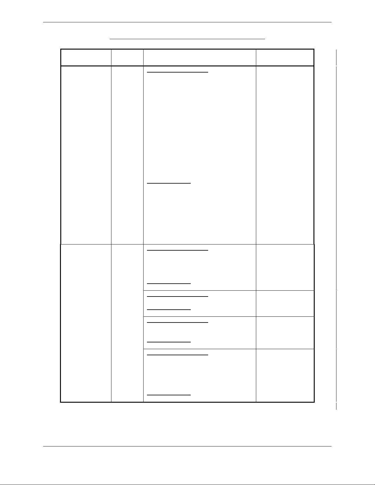
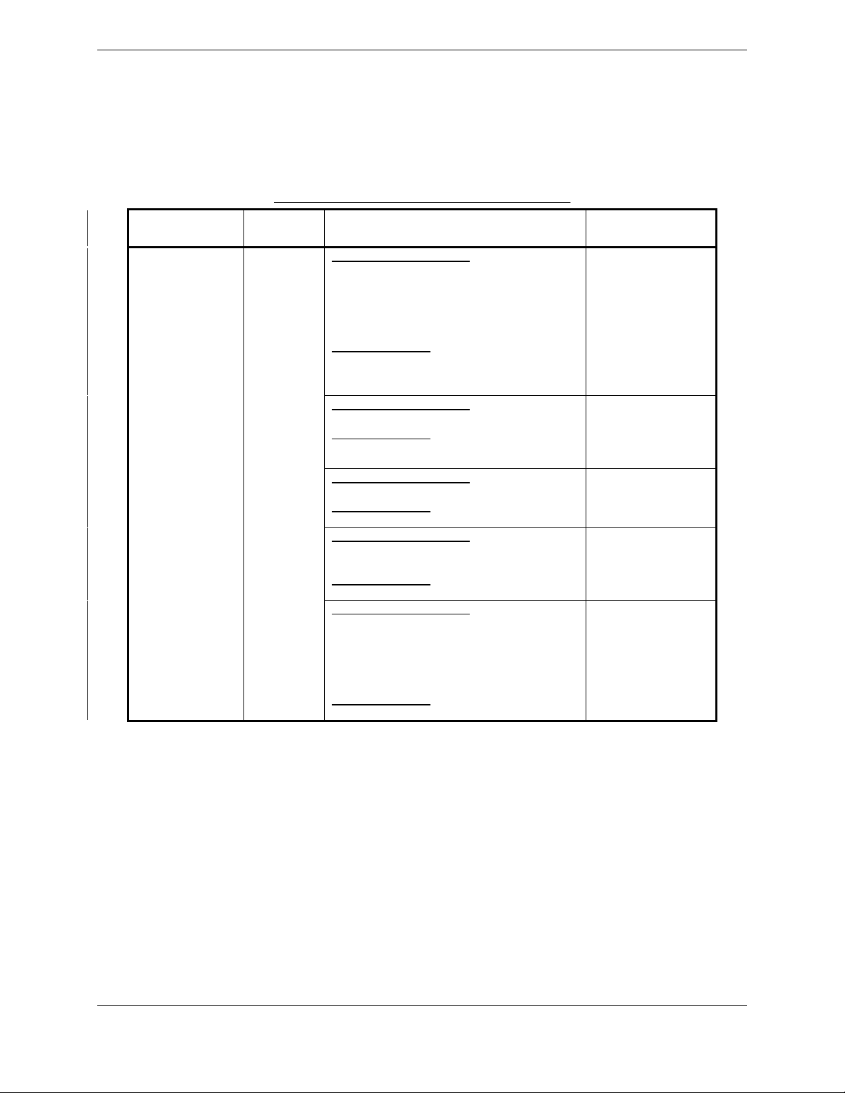
Table 1-1. MDL Configurations Summary (Cont.)
MDL
Configuration
-1 Configuration
(Cont)
-2 Configuration
Aircraft
System
G1000 &
GFC 700
with
WAAS
G1000 &
GFC 700
without
WAAS
Upgrades Available
Major Functions Added
• Optional Electronic Stability & Protection
• Optional GDL 59 /GSR 56B to include
WWWx, SMS Text Messaging and TEL
functionality
• Optional GSR 56B standalone to
include WWWx, SMS Text Messaging
and TEL functionality
• Addition of Profile View
• Addition of Synthetic Vision (SVS)
• Addition of Enhanced Search and
Rescue (SAR)
• Add optional installation of GSA 81 -20
servos and GSM 86 servo mounts.
• Automated Slip Clutch Test for GSM 86
Installations
• Misc. GDU v12.05 features
Hardware Added
• GDU 1040 P/N 011-00972-10
• GDU 1042 P/N 011-01080-10
• GDU 1044 P/N 011-01078-10
• GIA63W P/N 011-01105-20
• GMU44 P/N 011-00870-10
• GDL59 P/N 011-01746-00
• GSR56 P/N 011-02268-00
• GSM86 P/N 011-01904-03
• GSA81 P/N 011-00878-20
Major Functions Added
• G1000 & GFC 700 AFCS
• Coupled baro-VNAV
• GDU Charts
• Misc. GDU v8.02 features
Hardware Added
GDU 1044 MFD Optional
Major Functions Added
• Misc. GDU v8.20 features
Hardware Added
GDC 74A P/N 011-00882-10
Major Functions Added
• Misc. GDU v9.01 features
(Non WAAS Support)
Hardware Added
None
Major Functions Added
• Import Flt Plans from SD Card
• Temporary Waypoints
• Flight Data Logging to SD Card
• GDL69 Aviator Pro features
• Misc. GDU v9.15 features
Hardware Added
None
G1000 System
Software Version
0321.23
0369.13
0321.17
0321.19
0321.22
G1000 System Maintenance Manual – Diamond DA40/40F Page 1-3
190-00545-01 Revision G
Configuration
-3 Configuration
MDL
Table 1-1. MDL Configurations Summary (Cont.)
Aircraft
System
G1000 with
WAAS &
No AP
Upgrades Available
Major Functions Added
• WAAS
• GDU Charts
• Misc. GDU v8.02 features
Hardware Added
GIA 63W Integrated Avionics (qty 2)
GA35 GPS/WAAS antennas (qty 2)
Major Functions Added
• Misc. GDU v8.20 features
Hardware Added
GIA 63W P/N 011-01105-01
GDC 74A P/N 011-00882-10
Major Functions Added
• Misc. GDU v9.01 features
Hardware Added
None
Major Functions Added
• Misc. GDU v9.01 features
(Non WAAS Support)
Hardware Added
None
Major Functions Added
• Import Flt Plans from SD Card
• Temporary Waypoints
• Flight Data Logging to SD Card
• GDL69 Aviator Pro features
• Misc. GDU v9.15 features
Hardware Added
None
Major Functions Added
• Optional GDL 59 /GSR 56B to include
WWWx, SMS Text Messaging and TEL
functionality
• Optional GSR 56B standalone to include
WWWx, SMS Text Messaging and TEL
functionality
• Addition of Profile View
• Addition of Synthetic Vision (SVS)
• Addition of Enhanced Search and Rescue
(SAR)
• Misc. GDU v12.05 features
Hardware Added
• GDU 1040 P/N 011-00972-10
• GIA63W P/N 011-01105-20
• GMU44 P/N 011-00870-10
• GDL59 P/N 011-01746-00
• GSR56 P/N 011-02268-00
G1000 System
Software Version
0369.13
0321.17
0321.18
0321.19
0321.22
0321.23
Page 1-4 G1000 System Maintenance Manual – Diamond DA40/40F
Revision G 190-00545-01
Configuration
-4 Configuration
-5 Configuration
MDL
Table 1-1. MDL Configurations Summary (Cont.)
Aircraft
System
G1000
without
WAAS &
No AP
G1000 with
WAAS &
Honeywell
KAP 140
Upgrades Available
Major Functions Added
• GDU Charts
• Misc. GDU v8.02 features
Hardware Added
GDU 1044 MFD Optional
Major Functions Added
• Misc. GDU v8.20 features
Hardware Added
GDC 74A P/N 011-00882-10
Major Functions Added
• Misc. GDU v9.01 features
(Non WAAS Support)
Hardware Added
None
Major Functions Added
• Import Flt Plans from SD Card
• Temporary Waypoints
• Flight Data Logging to SD Card
• GDL69 Aviator Pro features
• Misc. GDU v9.15 features
Hardware Added
None
Major Functions Added
• Misc. GDU v8.20 features
Hardware Added
GIA 63W P/N 011-01105-01
GDC 74A P/N 011-00882-10
Major Functions Added
• Misc. GDU v9.01 features
Hardware Added
None
Major Functions Added
• Misc. GDU v9.01 features
(Non WAAS Support)
Hardware Added
None
Major Functions Added
• Import Flt Plans from SD Card
• Temporary Waypoints
• Flight Data Logging to SD Card
• GDL69 Aviator Pro features
• Misc. GDU v9.15 features
Hardware Added
None
G1000 System
Software Version
0369.13
0321.17
0321.19
0321.22
0321.17
0321.18
0321.19
0321.22
G1000 System Maintenance Manual – Diamond DA40/40F Page 1-5
190-00545-01 Revision G
Configuration
-5 Configuration
(Cont)
-6 Configuration
MDL
Table 1-1. MDL Configurations Summary (Cont.)
Aircraft
System
G1000 with
WAAS &
Honeywell
KAP 140
G1000
without
WAAS &
Honeywell
KAP 140
Upgrades Available
Major Functions Added
• Optional GDL 59 /GSR 56B to include
WWWx, SMS Text Messaging and TEL
functionality
• Optional GSR 56B standalone to include
WWWx, SMS Text Mesaging and TEL
functionality
• Addition of Profile View
• Addition of Synthetic Vision (SVS)
• Addition of Enhanced Search and Rescue
(SAR)
• Misc. GDU v12.05 features
Hardware Added
• GDU 1040 P/N 011-00972-10
• GIA63W P/N 011-01105-20
• GMU44 P/N 011-00870-10
• GDL59 P/N 011-01746-00
• GSR56 P/N 011-02268-00
Major Functions Added
• Misc. GDU v8.20 features
Hardware Added
GDC 74A P/N 011-00882-10
Major Functions Added
• Misc. GDU v9.01 features
(Non WAAS Support)
Hardware Added
None
Major Functions Added
• Import Flt Plans from SD Card
• Temporary Waypoints
• Flight Data Logging to SD Card
• GDL69 Aviator Pro features
• Misc. GDU v9.15 features
Hardware Added
None
G1000 System
Software Version
0321.23
0321.17
0321.19
0321.22
Page 1-6 G1000 System Maintenance Manual – Diamond DA40/40F
Revision G 190-00545-01

IMPORTANT!
If the technician is unsure of the G1000 MDL configuration, perform the following
steps:
Check System Software Version
1. Power on the G1000 system by turning on the BAT master switch, then the AVIONICS MASTER
switch.
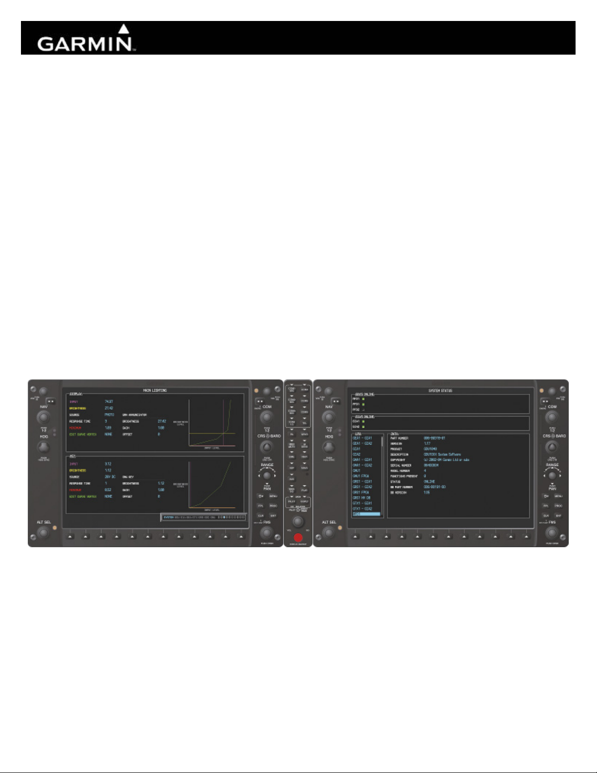
2. On the MFD power-up page, the G1000 system software version is displayed in the upper right corner
in the following format:
Diamond DA40 System XXXX.XX
-or Diamond DA40F System XXXX.XX
The system software version is also displayed at the AUX – SYSTEM STATUS page in the upper
right corner.
3. This system software version is the primary identifier of which G1000/GFC700 configuration is
installed. Refer to Table 1-1 for approved G1000 system software versions.
NOTE
The approved G1000 system software versions for this STC are listed in Table 1-1. If the
system software version differs from that shown in Table 1-1, investigate further to
determine which G1000 configuration is installed. Refer to the appropriate
G1000/GFC700 System Maintenance manual (see list of superseded manuals which may
apply in Section 1.1.1).
Check for GFC 700 AFCS Installation
To verify whether the GFC 700 AFCS is installed, do the following:
1. Check the G1000 MFD for dedicated AFCS mode control keys on the left side of the display (see
Figure 3-2).
2. Check the aircraft throttle lever for installation of a ‘Go Around’ (GA) button.
3. If the aircraft has these features installed, it is equipped with the Garmin GFC 700 autopilot.
4. The aircraft is either a -1 or a -2 MDL Configuration.
Check for WAAS Installation
To verify whether WAAS is installed, do the following:
1. On the MFD, go to the AUX – GPS STATUS page.
2. Check to see whether a softkey labeled SBAS is displayed. The SBAS softkey only appears if the
G1000 is equipped with GIA 63Ws.
3. If the SBAS softkey is present, the aircraft is a -1, -3, or a -5 MDL Configuration.
G1000 System Maintenance Manual – Diamond DA40/40F Page 1-7
190-00545-01 Revision G

Check for Optional Installations
Identify all installation options currently installed on the aircraft which interface to the G1000 and
check each that applies in the following list. These options may need to be re-configured if a new
system software version is loaded or an LRU is removed or replaced.
DA40 / DA40 F:
ADF
DME
GDL 69
Extended Range Fuel Tanks
Standard GFC 700
Enhanced GFC 700
Electronic Stability and Protection (ESP)
No Autopilot Installed (No KAP140 or GFC 700)
EASA Airspeed Tape (EASA Registered Aircraft Only)
Display of Fuel Pressure Gauge
TAWS
ChartView
Enhanced Search and Rescue (SAR)
Synthetic Vision and Pathway (SVS)
GDL 59 Data Link & GSR 56 Satellite Receiver
Standalone GSR 56 Satellite Receiver
DA40 F Only:
Fuel Pressure Sensor Installed
One CHT and EGT sensor installed
Four CHT and EGT sensors installed
The following are provisional options not certified by any Garmin STC. To enable these interfaces, a
separate installation approval is required.
Avidyne TAS 600
WX500 Stormscope
CO Guardian
Page 1-8 G1000 System Maintenance Manual – Diamond DA40/40F
Revision G 190-00545-01

1.2 Organization
The following outline briefly describes the organization of this manual:
Section 2: System Description
Provides a complete description of the type design change associated with installing the G1000
integrated cockpit system in the Diamond DA 40. An overview of the G1000 and GFC 700 system
interface is also provided.
Section 3: G1000 Control & Operation
Presents basic control and operation information specifically tailored to maintenance practices. Basic
G1000 Configuration Mode operation is also described.
Section 4: G1000 Instructions for Continued Airworthiness
FAA-Approved Instructions for Continued Airworthiness provides airworthiness limitations and
scheduled maintenance requirements for the G1000 and GFC 700 systems.
Section 5: Troubleshooting
Provides troubleshooting information to aid in diagnosing and resolving potential problems with the
G1000 and GFC 700 systems.
Section 6: G1000 Equipment Removal & Replacement
Gives instructions for the removal and replacement of G1000 and GFC700 equipment.
Section 7: G1000 Equipment Configuration & Testing
Gives instructions for loading software, configuring, and testing of G1000 equipment.
Section 8: System Return to Service Procedure
Specifies return-to-service procedures to be performed upon completion of maintenance of the G1000
system.
G1000 System Maintenance Manual – Diamond DA40/40F Page 1-9
190-00545-01 Revision G

1.3 Definitions/Abbreviations
The following are some common acronyms & definitions found throughout this manual:
ADI: Attitude Display Indicator
ADF: Automatic Direction Finder
AFCS: Automatic Flight Control System
AFMS: Airplane Flight Manual Supplement
AHRS: Attitude Heading Reference System
AMM: Airplane Maintenance Manual
CDI: Course Deviation Indicator
CDU: Control Display Unit
CFR: Code of Federal Regulations
DME: Distance Measuring Equipment
EAU: Engine/Airframe Unit
EIS: Engine Instrumentation Systems
ESP: Electronic Stability and Protection
GA Go Around
GDC Garmin Air Data Computer
GDL: Garmin Data Link
GDU: Garmin Display Unit
GEA: Garmin Engine Airframe Unit
GFDS: Garmin Flight Data Service
GIA: Garmin Integrated Avionics
GMA: Garmin Marker Beacon & Audio Panel Unit
GMU: Garmin Magnetometer Unit
GPS: Global Positioning System
GRS: Garmin Reference System
GS: Glideslope
GSA: Garmin Servo Actuator
GSM: Garmin Servo Mount
GSR: Garmin Satellite Radio
GTX: Garmin Transponder
HIRF: High Intensity Radiated Fields
HSDB: High-Speed Data Bus (Ethernet)
HSI: Horizontal Situation Indicator
IAU: Integrated Avionics Unit
ICA: Instructions for Continued Airworthiness
ICS: Inter-Com System
ILS: Instrument Landing System
LOC: Localizer
Page 1-10 G1000 System Maintenance Manual – Diamond DA40/40F
Revision G 190-00545-01

LPV: Localizer Precision with Vertical Guidance approach
LRU: Line Replaceable Unit
MET: Manual Electric Trim
MFD: Multi-Function Flight Display
OAT: Outside Air Temperature
OBS: Omni-Bearing Selector
PFD: Primary Flight Display
SAR Search and Rescue
STC: Supplemental Type Certificate
SVS Synthetic Vision System
SW: Software
TC: Type Certificate
TSO: Technical Standard Order
TVS: Transient Voltage Suppressor
WAAS: Wide Area Augmentation System
VHF: Very High Frequency
VOR: Very High Frequency Omni-directional Range
1.3.1 Units of Measure
Unless otherwise stated, all units of measure are English units.
G1000 System Maintenance Manual – Diamond DA40/40F Page 1-11
190-00545-01 Revision G

1.4 Publications
The following documents are required by this maintenance manual to perform maintenance:
DA4-9231-60-01
DA4-9231-60-05
Table 1-2. Required Documents
Part Number Document
005-00400-01 STC Master Drawing List
005-00400-08
005-00400-09
005-00400-10
005-00400-11
005-00400-15
005-00400-16
005-00400-12
005-00400-13
005-00400-55
OR
6.02.01 Diamond DA 40 Airplane Maintenance Manual (Diamond Part Number)
005-00400-92 Instl,Pitch Servo,GFC700 with GSM 86, Diamond DA40/40F
005-00400-93 Instl,Pitch Trim Servo,GFC700 with GSM 86, Diamond DA40/40F
005-00400-94 Instl,Roll Servo,GFC700 with GSM 86, Diamond DA40/40F
005-00464-10 Installation Modification, G1000/GFC700, WAAS, Diamond DA40/40F
005-00464-15 Installation Modification, G1000, WAAS, No Autopilot, Diamond DA40/40F
005-00464-00 Installation Modification, G1000/KAP140, WAAS, Diamond DA40/40F
005-00464-07 Antenna Install, GDL59/GSR56, DA40/40F
005-00464-08 GDL59/GSR56 Install, DA40/40F
005-00464-06 Wiring Diagram,GDL59/GSR56 in DA40/40F
005-00464-12 Wiring Diagram, GTX 33 Relocation, Diamond DA40 / DA 40 F
005-00464-13 Wiring Routing, GTX 33 Relocation, Diamond DA40 / DA 40 F
190-00355-04 GDL 69 Series XM Satellite Radio Activation Instructions
General Arrangement, G1000/KAP140, WAAS, Diamond DA40/40F
(-5 MDL Configuration)
General Arrangement, G1000/KAP140, no WAAS, Diamond DA40/40F
(-6 MDL Configuration)
General Arrangement, G1000/GFC700, WAAS, Diamond DA40/40F
(-1 MDL Configuration)
General Arrangement, G1000/GFC700, no WAAS, Diamond DA40/40F
(-2 MDL Configuration)
General Arrangement, G1000 Only, WAAS, Diamond DA40/40F
(-3 MDL Configuration)
General Arrangement, G1000 Only, no WAAS, Diamond DA40/40F
(-4 MDL Configuration)
Resistor Installation Drawing, G1000, WAAS, Diamond DA40/40F
(-1 & -3 MDL Configurations)
Resistor Wiring Diagram, G1000, WAAS, Diamond DA40/40F
(-1 & -3 MDL Configurations)
Optional Dual Audio Path Wiring For TAWS Installations in Diamond DA40 /
DA40F
Diamond Wiring Diagram
(Diamond Part Number, -05 applies to GFC700 aircraft)
Page 1-12 G1000 System Maintenance Manual – Diamond DA40/40F
Revision G 190-00545-01
The following design drawings are carried over from the prerequisite previously approved STCs for
continued airworthiness purposes.
IMPORTANT!
Previous STC General Arrangement drawings, Required Equipment Lists, and
hardware/software equipment lists are obsolete and are now superseded by the new
General Arrangement drawings provided in Table 1-2. The following type design data
still applies to previously installed equipment.
Table 1-3. Previously Approved Type Design
Part Number Document STC#
005-00304-00
005-00336-17
005-00336-18
005-00336-19
G1000 Install, Diamond DA40/40F SA01254WI-D
Pitch Servo Installation, GFC700 AFCS, Diamond DA40/40F
Roll Servo Installation, GFC700 AFCS, Diamond DA40/40F
Pitch Trim Servo Installation, GFC700 AFCS, Diamond DA40/40F
SA01389WI
The following publications are recommended to be available during maintenance activities.
Table 1-4. Reference Publications
Part Number Document
005-00304-00
190-00492-08
190-00492-09
190-00492-10
190-00492-11
190-00492-12
G1000 Install, Diamond DA40/40F
Airplane Flight Manual Supplement: G1000 Synthetic Vision And Pathways Option
Airplane Flight Manual Supplement: G1000 Electronic Stability and Protection (ESP)
Option for the Diamond DA40/DA40F
Airplane Flight Manual Supplement: G1000 Integrated Avionics System with GFC 700
Automatic Flight Control System – Diamond Model DA40 & DA40F
Airplane Flight Manual Supplement: G1000 Integrated Avionics System – Diamond
Model DA40 & DA40F
Airplane Flight Manual Supplement: G1000 Integrated Avionics System – Diamond
Model DA40 & DA40F
190-00324-07
190-00324-08
190-00324-09
G1000/GFC700 DA 40 Cockpit Reference Guide*
190-00324-10
190-00324-11
190-00355-04
190-00303-72
GDL 69/69A XM Satellite Radio Activation Instructions
GSA8X/GSM85(A) Installation Manual
*See AFMS for correct CRG P/N required.
G1000 System Maintenance Manual – Diamond DA40/40F Page 1-13
190-00545-01 Revision G

1.5 Distribution
This document is required for maintaining the continued airworthiness of aircraft equipped with this STC.
Revisions to this document will be made by Garmin and will be distributed by Garmin per standard
documentation revision procedures.
For the latest revision to this document, check Garmin’s web site at: www.garmin.com/ and click on
‘Dealer Resource Center’.
NOTE
Only Garmin-authorized dealers and service centers are given access to the Dealer
portion of the Web Site. If you do not have a Dealer Password, contact Garmin directly
to obtain the latest revision of this document.
1.6 Required Materials & Equipment
The following test equipment is required to conduct and complete all post installation checkout
procedures in this section (All test equipment should have current calibration records):
A ground power unit capable of supplying 28 Vdc power to the aircraft systems and avionics.
Outdoor line-of-site to GPS satellite signals or GPS indoor repeater.
Outdoor line-of-site to Iridium satellite signal.
Headset/Microphone.
A VHF NAV/COM Test Set
Air Data Test Set
L-Band Multi-Function Test Set
The following materials are defined on the applicable General Arrangement Drawing (see STC MDL):
G1000/DA40 Software Image
SD Card,GDU10XX BB Ldr,v2.03 (May be required. Refer to Section 3.5.3)
SD Card,G1000,GIA6X BBL 4.01(May be required. Refer to Section 3.5.7)
SD Card,GDU10xx Supp SVS, (TRN/OBS/APT DB/SUPP/SAFE TAXI)*
SD Card,GDU10xx TAWS Unlock (Optional)
SD Card,GDU10XX,Chart Unlock, Light AC (Optional)
SD Card, GDU1XXX Enhanced AFCS Unlock (Optional)
SD Card, G1000, Enhanced SAR Unlock (Optional)
SD Card,GDU10xx SVS Unlock,1 PFD (Optional)
*Terrain database cards are required by this STC. However, the newer updated cards which provide
SafeTaxi and Chart capability are an optional upgrade. If these newer cards are not installed, the existing
installed cards must still be used. Reference the applicable General Arrangement Drawing (see STC
MDL). See the applicable General Arrangement Drawing for each configuration in Master Drawing List,
005-00400-01 for additional details.
Table 1-5 lists the loader cards used in this upgrade and is derived from the appropriate General
Arrangement drawing for each configuration listed on MDL 005-00400-01. The appropriate General
Arrangement drawing should be followed if any differences exist.
Page 1-14 G1000 System Maintenance Manual – Diamond DA40/40F
Revision G 190-00545-01
R
O
*
†
NA
Qty
Table 1-5. Loader Card to Configuration Relationship Summary
Legend
Required
Optional
See Note 1
See Note 2
Not Applicable
010 - P/N
and
006 - P/N
(Where Applicable)
Description
Config -1
Config -2
Config -3
Config -4
Config -5
Config -6
1 ea
2 ea 010-00330-43
1 ea 010-00330-51
1 ea 010-00330-53
1 ea
1 ea
1 ea 010-00330-5B
1 ea 010-00330-59
1 ea 010-00330-54
(*) Note 1 - REQUIRED - Only if determined necessary to update GDU 104X boot block per section 3.5.3 procedures.
(†) Note 2 – REQUIRED - Only if determined necessary to update GIA 63 boot block per section 3.5.7 procedures.
010-00369-XX
006-B0321-XX
010-00330-02
006-B0874-00
010-00533-00
006-B0538-00
SD Card,G1000,DA40
Ldr
SD Card,GDU10xx Supp
SVS
(TRN/OBS/APT
DB/SUPP/SAFE TAXI)
SD Card,GDU10xx
TAWS Unlock
SD Card,GDU10XX,Chart
Unlock, Light AC
SD Card,GDU10XX BB
Ldr,v2.03
SD Card,G1000,GIA6X
BBL 4.01
SD Card, GDU1XXX
Enhanced AFCS Unlock
SD Card, G1000,
Enhanced SAR Unlock
SD Card,GDU10xx SVS
Unlock,1 PFD
R R R R R R
R R R R R R
O O O O O O
O O O O O O
* * * * * *
† † † † † †
O NA NA NA NA NA
O O O O O O
O O O O O O
The G1000/ DA40 Software Image file, Boot Block update for the GDU 104X and GIA 63 may be
electronically sourced via the listed 006- P/N. through Garmin to facilitate building a boot block software
SD Card. If desired, technician may purchase the Boot Block cards as a higher – level assembly produced
by Garmin, defined per the 010 – P/Ns shown above.
NOTE
When an option is enabled for the first time (normally at the Diamond factory), the
G1000 writes its unique system ID to the physical card and locks the files to this unique
ID. This prevents the unlock card from ever being used to activate the feature in other
G1000 systems. The unlock card is forever tied to the specific aircraft in which it was
used for the first time. For situations where the feature must be re-activated, this card
must be used. If the original G1000 feature unlock card is not available the technician
may purchase the unlock cards as a higher – level assembly produced by Garmin, defined
per the 010 – P/Ns shown above or contact Garmin customer support.
G1000 System Maintenance Manual – Diamond DA40/40F Page 1-15
190-00545-01 Revision G

This page intentionally left blank.
Page 1-16 G1000 System Maintenance Manual – Diamond DA40/40F
Revision G 190-00545-01

2 SYSTEM DESCRIPTION
2.1 STC Requirements Overview
The -1 and -2 STC configurations require the following STCs to be installed on the aircraft prior or
concurrently to the installation of this STC:
STC #SA01254WI-D Garmin G1000 in Diamond DA40 / 40F
STC #SA01389WI Garmin GFC 700 in Diamond DA40 / 40F
For the -3, -4, -5, and -6 configurations of this STC, only STC #SA01254WI-D is required to be installed.
Certain Diamond Optional Aircraft Modifications (OAM) are part of the initial type design requirements
for the above STCs. These modifications define much of the systems and electrical design for the Garmin
G1000 and GFC 700 and are installed by the Diamond factory. The following OAMs may be installed on
a DA40 equipped with the G1000, depending on STC configurations:
DA40 & DA40F Aircraft:
OAM 40-226 G1000/GFC700 Provisions
OAM 40-061 KAP 140 Autopilot (Optional)*
OAM 40-068 Essential Bus
OAM 40-073 Slick Start System
OAM 40-082 IFR Lightning Protection
OAM 40-146 Remote Avionics Provisions
OAM 40-071 Extended Range Fuel Tanks
OAM 40-162 G1000 with Extended Range Fuel Tanks
OAM 40-210 Provisions for Becker RA3502 ADF
OAM 40-211 Provisions for Honeywell KN63 DME
OAM 40-213 Provisions for Garmin GDL 69A
DA40 Aircraft Only:
OAM 40-161 G1000 Provisions with KAP 140*
OAM 40-196 G1000 Provisions without KAP 140
STC #SA1840SC Hartzell Propeller
DA40F Aircraft Only
OAM 40-222 G1000 in DA40F Provisions
*Currently only supported by the -5 and -6 STC configurations. The KAP140 Autopilot has been certified for use with G1000
System Software version 0321.17 or later by this STC.
G1000 System Maintenance Manual – Diamond DA40/40F Page 2-1
190-00545-01 Revision G

2.2 Equipment Descriptions
2.2.1 GDU 1040 PFD & GDU 1040, 1042, or 1044 MFD
Two Garmin GDU 1040 displays are installed in the Diamond instrument panel. One is configured as a
PFD and the other as a MFD (Configuration is determined by wiring harness). Both displays provide
control and display of nearly all functions of the G1000 integrated cockpit system. The displays are
located side-by-side with the GMA 1347 Audio Panel located in the middle. For GFC 700-equipped
aircraft, the MFD is either a GDU 1042 or GDU 1044. Both are distinguished by their dedicated AFCS
control keypad on the lower left bezel. The GDU 1044 has an additional VNV key which allows for
coupled-VNAV descents.
Electrical power to the PFD is from the ‘Essential’ power bus, whereas the MFD receives power from the
‘Main’ power bus. Therefore, both displays power-up immediately when the aircraft master switch is
turned on. To provide proper electrical bonding, beryllium copper ‘finger’ strips are installed on the
lower lip of the display. This provides sufficient contact area to which the displays can be grounded to
the airframe.
Both displays are installed in the Diamond panel using built-in ¼-turn fasteners. Each display uses an
existing connector per OAM 40-161 or OAM 40-226.
Two cooling fans are also installed behind the panel for PFD and MFD cooling.
For MDL configurations -1,-3 and -5 only, this STC installation approves alternate part numbers for the
displays that accept external video input and have an additional HSDB Ethernet connection. There are no
mechanical or electrical interface changes needed for these new part number displays. Refer to the
applicable General Arrangement Drawing listed in Table 1-2 for part number information.
NOTE
While the alternate part numbers of displays authorized by this STC include an external
video input and HDSB Ethernet connection, this STC does not approve any interfaces to
these ports. These ports are not configured on by this STC. Any interfaces to these ports
will require activation of these ports and additional airworthiness approvals will be
required.
2.2.2 GMA 1347 Audio Panel
The Garmin GMA 1347 Audio Panel is a digital audio panel with integrated marker beacon receiver. The
GMA 1347 provides control of all cockpit intercom/mic systems as well as NAV/COM/ILS audio. The
unit also provides display reversion mode control through a large red button. Power is received from the
‘Essential’ bus. The unit powers up when the aircraft master switch is turned on. The GMA 1347
interfaces with the existing marker beacon antenna as well as existing mic and phone jacks.
Page 2-2 G1000 System Maintenance Manual – Diamond DA40/40F
Revision G 190-00545-01

2.2.3 GIA 63 or GIA 63W Integrated Avionics Unit (2)
NOTE
For MDL configurations -1,-3 and -5 only, this STC installation approves alternate part
number ‘-20’ GIA63Ws. The installation of these units will require software version
0321.23 or later as well as mechanical and wire harness changes to relocate the GTX33
transponders (refer to Section 2.2.5). Refer to the applicable General Arrangement
Drawing listed in Table 1-2 for part number and software information.
Two Garmin GIA 63 IAUs provide VHF COM, NAV, GS, and GPS navigation functions to the G1000.
GIA 63W models include a GPS/WAAS engine. GIAs also serve as a communication interface to all
other G1000 LRUs in the system. Both GIAs are located remotely beneath the baggage compartment in a
sheetmetal enclosure. The #1 GIA is powered through the ‘Essential’ power bus and immediately powers
up when the aircraft master switch is turned on. The #2 GIA receives power through the ‘Main Avionics’
bus and powers up when the avionics master switch is turned on. Both GIA 63s interface to the following
equipment:
• Existing VOR/LOC/Glideslope Antenna System
• Existing VHF COM 1 & 2 Antennas
• Existing Garmin GA56 GPS1 & 2 Antennas (GIA 63 only)
• GA35 GPS/WAAS Antennas (GIA 63W only)
2.2.4 GEA 71 Engine/Airframe Unit
The Garmin GEA 71 Engine/Airframe Unit provides engine/airframe data to the G1000 system. Data
received from transducers/sensors is processed, then sent to GIA 63, and subsequently to the GDU 1040
MFD. In display reversionary mode, engine instrumentation is displayed on the PFD as well. The GEA
is located behind the instrument panel and is mounted in a vertical orientation. Power is received from
the ‘Essential’ power bus. The GEA interfaces to the following:
• Manifold Pressure Sensor (MAP, DA 40 aircraft only)
• Oil Pressure Sensor
• Fuel Pressure Sensor
• Tachometer Sensor
• Oil Temperature Sensor
• Fuel Flow Sensor
• 4 Cylinder Head Temperature (CHT) Sensors
• 4 Exhaust Gas Temperature (EGT) Sensors
• Alternator Current Sensor
• Existing Fuel Probes
• Existing Pitot Heat System
• Existing Open Door Detection Switches
• Existing Starter Engage System
NOTE
STC SA01254WI-D provisions engine/airframe sensors for the Diamond DA 40 aircraft
only. For DA 40 F aircraft with fixed-pitch propellers, all engine sensors are provisioned
and installed per Diamond OAM 40-222.
G1000 System Maintenance Manual – Diamond DA40/40F Page 2-3
190-00545-01 Revision G

2.2.5 GTX 33 Mode S Transponder
The Garmin GTX 33 provides Mode A, C, and S altitude and position reporting information to the G1000
system.
• Aircraft with GIA 63W P/N 011-01105-00 or 011 01105-01, the unit is mounted in the remote
avionics enclosure below the baggage compartment.
• Aircraft with GIA 63W P/N 011-01105-20, the unit is mounted on the outboard side of the
remote avionics enclosure below the baggage compartment.
Power is received from the ‘Essential’ bus. The GTX 33 interfaces with the existing transponder antenna.
2.2.6 GDC 74A Digital Air Data Computer
The Garmin GDC 74A provides digital air data computations to the G1000 system. The unit is mounted
horizontally behind the instrument panel and is fastened to a rack. Power is received from the ‘Essential’
bus. The GDC 74A connects to existing pitot/static ports.
2.2.7 OAT Probe
The Garmin GTP 59 OAT Probe provides the GDC 74A with air temperature data. The OAT probe is
mounted to the bottom starboard side of the DA 40 fuselage.
2.2.8 GRS 77 Attitude & Heading Reference System
The Garmin GRS 77 AHRS provides attitude and heading information to the G1000 system. The unit is
mounted remotely in the baggage compartment, to the starboard side of the remote avionics enclosure.
Power is received from the ‘Essential’ bus. The GRS 77 interfaces with and provides power to the
GMU 44 Magnetometer. The GRS 77 supplies attitude and heading information directly to the PFD,
MFD, and to both GIAs.
2.2.9 GMU 44 Magnetometer
The GMU 44 provides horizontal and vertical magnetic field information to the GRS 77 AHRS. This
allows heading to be calculated and provides assistance during AHRS alignment. The GMU 44 is
mounted beneath the starboard wing.
2.2.10 GDL 69A (Optional)
The GDL 69A provides optional XM Radio weather and music entertainment through means of a
dedicated satellite data link. The GDL 69A is mounted in the remote avionics enclosure. Power to the
GDL 69A is received from the ‘Main Avionics’ bus. The GDL 69A sends weather data through the
HSDB bus to the MFD, where the data link interface is controlled. Digital audio is sent directly to the
GMA 1347.
2.2.11 Remote Avionics Enclosure
Refer to 005-00304-00, Sheets 2 & 8:
A remote avionics enclosure allows LRUs to be inserted vertically, from above. The enclosure is also
cooled with an avionics fan and duct assembly. The assembly is grounded to an existing grounding
station using a field-fabricated aluminum ground strap. Two braided grounding straps are also attached to
the GRS 77 rack from the enclosure. A Comant diplexer is installed on the enclosure as shown. A fieldfabricated component bracket with resistors, voltage suppressors and attached wiring is fastened to the
forward portion of the enclosure.
Page 2-4 G1000 System Maintenance Manual – Diamond DA40/40F
Revision G 190-00545-01

2.2.12 GDL 59 Datalink (Optional)
The GDL 59 provides the interface to an optional GSR 56 satellite datalink, which adds airborne low
speed data link and voice communication capability. The GDL 59 unit interfaces to the Garmin
Integrated Flight Deck via the GDL69A using HSDB. The GDL 59 is located below the baggage
compartment and power is received from the Avionics bus.
2.2.13 GSR 56 Satellite Transciever (Optional)
The GSR 56 provides airborne low speed data link and voice communication capability to Garmin
Integrated Flight Deck installations. The GSR 56 contains a transceiver that operates on the Iridium
Satellite network. The GSR 56 interfaces directly to the GDL 59 via an RS-232 interface for the
GDL 59 / GSR 56 combination option. The Standalone GSR 56 option interfaces directly to GIA #2 via
an RS-232 interface. The GSR 56 is located below the baggage compartment and power is received from
the Avionics bus.
2.3 G1000 Optional Interfaces
Installation of all other optional equipment that interfaces to the G1000, including ADF, DME, and
GDL 69A is documented by Diamond OAM factory drawings.
2.3.1 KAP 140 AFCS
The Phase 7 amendment to STC SA01444WI-D adds two new installation configurations to the MDL
(See Table 1-1), both of which allow for G1000 systems with GDU 8.20 and greater to interface with
existing DA40 aircraft equipped with the Honeywell KAP 140 AFCS.
The G1000 interfaces to the KAP 140 by providing the following from the #2 GIA 63:
-Output of Lateral & Vertical Navigation Signals
-Output of Course Datum
-Output of Heading Datum
-Output of Encoded Altitude
-ILS Energize Discrete
-GPS Select Discrete
Additionally, the G1000 receives the following from the KAP 140:
-Pitch Trim Fail Discrete Input
-Pitch Trim Fail Aural Input
The G1000 – KAP 140 interface was included as part of the original G1000 certification under STC
SA01254WI. In order to be compatible with WAAS, GDU software changes were made as part of
System Software Version 0321.17 or later, which were certified as a follow-on amendment to STC
SA01444WI-D.
2.3.2 Synthetic Vision System
The Synthetic Vision System (SVS) provides the crew with a greater awareness of the aircraft’s position
relative to surrounding terrain, obstacles, and traffic (optional). SVS is an embedded software feature of
the G1000 and is controlled by using PFD softkeys. Specific details on operating the SVS feature can be
found in the Synthetic Vision & Pathways AFMS specified in Table 1-4.
SVS enhances situational awareness by displaying a three dimensional depiction of terrain, obstacles, and
traffic in the PFD primary field of view such that their proximity to the aircraft is more easily understood
during instrument scanning. The display of SVS can be turned on and off by the pilot by a dedicated
softkey on the PFD.
G1000 System Maintenance Manual – Diamond DA40/40F Page 2-5
190-00545-01 Revision G

The SVS PFD frame-of-reference is aligned with the aircraft body frame, using AHRS attitude and
heading data for orientation. Accordingly, the SVS is egocentric and attitude-aligned. GPS position and
GPS-derived altitude are used for the SVS position and elevation references, respectively. The SVS 3D
terrain presentation is generated from a high resolution 9 arc-second terrain database image. For the SVS
system to be made available by the G1000, valid attitude, heading, GPS position, and terrain databases are
required.
All previous existing PFD display features are retained and drawn over the SVS. For example, airspeed,
altitude, vertical speed, heading, and HSI items will remain unchanged, and will be drawn over the SVS
presentation.
Figure 2-1. SVS/Pathways Feature
Synthetic Vision System:
3D Terrain Rendering on PFD – SVS system will utilize an egocentric, forward looking perspective of 3D
terrain rendering and shading, to be displayed on the PFD.
Zero Pitch Line – The PFD displays an artificial horizon pitch reference line above the display of terrain,
similar to the existing artificial horizon which currently separates the blue/brown attitude depiction. The
display of horizon heading marks in 30° intervals on the pitch line is a pilot-selectable feature.
Flight Path Marker – The projected aircraft flight path is displayed in the form of a Flight Path Marker on
the PFD.
Display of Traffic – Traffic data from existing certified TIS, provided by the G1000 GTX 33 Mode-S
transponder, is used to generate on-screen traffic symbols.
Display of Land-based Objects – Obstacles, runways, water bodies, and other land features are displayed
on the PFD.
Pathways:
Page 2-6 G1000 System Maintenance Manual – Diamond DA40/40F
Revision G 190-00545-01

SVS / Pathways are a pilot-selectable feature. The display of SVS can be turned on and off by the pilot by
a dedicated softkey on the PFD. The display of Pathways requires that the 3D Terrain feature be
displayed (i.e. SYN TERR softkey pressed).
When active, the Pathway is displayed on the PFD and will show flight path information in the form of a
virtual 3D flight path, composed of rectangular elements which form a tunnel. The depiction of this
pathway is derived from the existing FMS navigation capabilities of the G1000, and the display will be
consistent with that of the active flight plan shown on the MFD.
2.4 GFC 700 AFCS System Description
For system software versions 0321.22 and earlier there was only one GFC 700 option which is
represented by the Standard GFC 700 description listed below.
• GFC 700 - GSM 85 Servo Gearbox and GSA 81 Servo Actuator
(P/N 011-00878-00)
For system software version 0321.23 and later the GFC 700 AFCS System has two (2) possible
installation options.
Dependent on the desired aircraft configuration the appropriate option will be selected and loaded. The
two options are listed below:
• Standard GFC 700 - GSM 85 or GSM 86 Servo Gearbox and GSA 81 Servo Actuator
(P/N 011-00878-00)
• Enhanced GFC 700 – GSM 86 Servo Gearbox (P/N 011-01904-03) and GSA 81 Servo
Actuator (P/N 011-00878-20)
Enhanced GFC 700:
An option for GFC 700 with GSM 86 Servo Gearbox (P/N 011-01904-03) and GSA 81 Servo Actuator
(P/N 011-00878-20) is available to the DA40 / DA40F. For this option the GSA 81 Pitch, Pitch Trim,
and Roll Servos software has been introduced at version 3.11. This option was added to allow enhanced
LRU and system operation and is a requirement for future GFC 700 functionality.
New functionality provided by the Enhanced GFC 700 option is as follows:
• GSM Automated Slip Clutch Torque Check
• Autopilot Expanded Engagement
• Aural AIRSPEED alert
G1000 System Maintenance Manual – Diamond DA40/40F Page 2-7
190-00545-01 Revision G

Standard GFC 700:
The Standard GFC 700 with GSM 85 or GSM 86 Servo Gearbox and GSA 81 Servo Actuator
(P/N 011-00878-00) is maintained as the previously certified configuration.
The Standard or Enhanced GFC 700 is a two-axis fail-safe digital flight control system that is integrated
within the G1000 system. The only distinguishing hardware from a non autopilot G1000 installation is
the MFD, the GSA 81 Servos and GSM 85 or GSM 86 Servo Mounts.
The following functions are provided by the GFC 700 in this installation:
• Flight Director
• Autopilot
• Manual Electric Trim
Flight Director:
The Flight Director operates within the #1 GIA 63 and uses data from the G1000 system, including air
data, attitude, and navigation data, to calculate commands for display to the pilot and for the Autopilot.
Flight Director command bars and mode annunciations are sent to the PFD through a high-speed Ethernet
connection for display to the pilot. The Flight Director operates independently of the Autopilot, and
allows the pilot to hand-fly the command bars, if desired.
Autopilot:
The Autopilot operates within the three GSA 81 servos. Flight Director data is processed within the three
servos and turned into aircraft flight control surface commands. The Autopilot cannot operate unless the
Flight Director is engaged.
Manual Electric Trim:
Independent of the Flight Director and Autopilot, Manual Electric Trim (MET) allows the pilot to control
the elevator trim tab by the MET switch located on the pilot control stick. Engaging both sides of the
switch in the same direction causes the autopilot to disengage (if engaged) and drives the pitch trim servo
in the desired direction. The ARM side of the MET switch may also be used to disconnect the autopilot
and cancel the resulting AP DISC alerts.
Page 2-8 G1000 System Maintenance Manual – Diamond DA40/40F
Revision G 190-00545-01

Figure 2-2. AFCS System Block Diagram
G1000 System Maintenance Manual – Diamond DA40/40F Page 2-9
190-00545-01 Revision G

2.4.1 GFC 700 Electrical Aspects
The wiring and switches used by the GFC 700 are provisioned by Diamond under OAM 40-226, and are
not included in the Garmin GFC 700 STC design. In general, the pitch and pitch trim servos are wired in
parallel to both GIA 63s and use the RS-485 serial protocol to communicate while the pitch servo has its
own line to both GIAs. See the Diamond wiring diagrams listed in Table 1-2 for more details on wiring.
The Diamond provisions also include the following switches:
AP DISC Switch
There are two large red AP DISC switches located on the pilot and copilot control sticks. When normally
closed, +28 VDC is allowed to pass through to the SERVO ENABLE pins of each servo, allowing the
Autopilot and servos to operate. When pushed, the switches break the +28VDC source and the Autopilot
disconnects and takes the servos offline.
CWS Switch
A control wheel steering switch is located on the pilot’s control stick. When pressed, this switch activates
CWS mode. The Autopilot, if engaged, is temporarily disengaged, and the Flight Director command bars
immediately synchronize to the current aircraft pitch and roll attitude. When released, the Autopilot will
re-engage (if previously engaged) and the Flight Director will orient itself to the last known pitch and roll
reference established during CWS mode. This allows the pilot to hand fly the aircraft when desired and
also allows the pilot to reestablish a desired aircraft flight attitude for the Autopilot to maintain.
MET Switch
See previous functional description of MET.
GA Switch
A Go-Around switch is installed within the engine throttle knob and activates the GA Flight Director
mode. During this mode, the Autopilot disengages (if engaged) and the Flight Director displays a 7° pitch
up nose attitude for reference during a missed approach or go-around procedure.
Page 2-10 G1000 System Maintenance Manual – Diamond DA40/40F
Revision G 190-00545-01

2.4.2 GSA 81 Servo and GSM 85 or GSM 86 Servo Mount
Figure 2-3. GSA 81 & GSM 85 or GSM 86
The GSA 81 is mated to the GSM 85 or GSM 86 Servo Mount to form a single servo unit. There are
three servo units in this installation:
• Pitch
• Pitch Trim
• Roll
The design of the servo assembly allows the servo actuator (GSA 81) to be removed from the servo
mount (GSM 85 or GSM 86) without the need to de-rig the aircraft control cables. The servo mount
contains the capstan (cable for roll/pitch, chain for pitch trim) and the slip clutch which allows a pilot to
manually overpower the Autopilot.
The GSM 85 has a slip clutch that can be adjusted to a desired torque value. The GSM 86 has a clutch
cartridge that cannot be adjusted to a different torque value.
2.5 Envelope Stability & Protection Description
System software version 0321.23 and later supports the optional Electronic Stability and Protection (ESP)
function. ESP assists the pilot in maintaining a safe flight condition within the aircraft flight envelope,
defined by pitch, roll, and airspeed. ESP is only active during flight with the autopilot off, and is only
available on G1000-equipped DA40 aircraft that also have a GFC 700 autopilot with the Enhanced AFCS
option installed.
ESP is automatically enabled when the aircraft exceeds one or more pre-determined thresholds beyond
normal flight. ESP engages the appropriate servo(s) in protection mode with low torque and gradually
increases the stick forces so the airplane naturally returns back to the desired flight envelope. The DA40
ESP activation thresholds are as follows:
• Roll threshold activation is 45 degrees for both the left and right roll conditions.
• Pitch threshold activation is 15 degrees for pitch up and 18 degrees for pitch down.
• High Airspeed threshold activation is 180 Knots Indicated Airspeed (KIAS) for high airspeed.
As the airplane deviates further from the desired flight envelope, the servo torque is increased in the
direction required to return to the desired flight envelope until the maximum torque level is reached. As
the airplane continues to deviate, the torque level remains constant up to the maximum engage limit.
G1000 System Maintenance Manual – Diamond DA40/40F Page 2-11
190-00545-01 Revision G

Above the maximum engage limit, ESP is not provided. The maximum thresholds for deactivation of the
ESP system on the Diamond DA 40 are as follows:
• Roll threshold deactivation outside of normal roll envelope is 75 degrees for both the left and
right roll conditions.
• Roll threshold deactivation returning to normal roll envelope is 30 degrees for both the left and
right roll conditions.
• Pitch threshold deactivation outside of normal pitch envelope is 20 degrees for pitch up and 23
degrees for pitch down.
• Pitch threshold deactivation returning to normal pitch envelope is 10 degrees for pitch up and 13
degrees pitch down.
• High Airspeed threshold deactivation occurs when the normal airspeed is 175 KIAS.
Once ESP protection is being provided and ESP is active for 50% of the last 20 seconds, the autopilot
engages in LVL mode returning the aircraft to a level flight envelope. When the autopilot engages
automatically an aural “ENGAGING AUTOPILOT” alert sounds and the Flight Director mode
annunciations will indicate LVL for the pitch and roll modes.
The pilot can interrupt the ESP function in manual flight by pressing and holding either the Control
Wheel Steering (CWS) or Autopilot Disconnect (AP DISC) switch. ESP can also be overridden by
overpowering the servo’s ESP electronic torque limit.
ESP and Autopilot are mutually exclusive functions and have separate electronic torque limits for its
specific function.
The pilot may also disable ESP by accessing the Multi-Function Display (MFD) Auxiliary System Setup
page on the MFD and manually disabling ESP. If the MFD circuit breaker is cycled while on the ground
or in flight the G1000 system will default ESP to “Enabled”. An advisory message is posted on the
G1000 when ESP is disabled
Page 2-12 G1000 System Maintenance Manual – Diamond DA40/40F
Revision G 190-00545-01

2.6 Electrical Power Distribution
Distribution of power to the G1000 occurs on three buses:
Essential Bus:
master switch is turned on, power is immediately supplied the ‘Essential’ bus. The ‘Essential’ bus is tied
via a relay switch to the ‘Main’ aircraft bus. There are two circuit breakers on either side of the relay,
combined with a single diode, allowing the battery to be charged by the alternator. Only equipment
deemed essential for safe flight is connected to this bus.
Main Aircraft Bus:
bus. After the aircraft engine is started, the alternator supplies power to the aircraft ‘Main’ bus, and to the
rest of the system. In the event of an alternator or other power failure, the ‘Essential’ bus can be isolated
with the ‘Essential Bus’ switch. This causes the ‘Essential’ bus to revert to battery power. Only the MFD
receives power from the ‘Main’ bus.
Main Avionics Bus:
switch and switch relay. The #2 GIA 63, the ADF, DME, GFC 700 AFCS, and the GDL 69A are
connected to this bus.
The ‘Essential’ bus is tied directly to the aircraft battery via the master switch. When the
The ‘Main’ bus receives power from the aircraft battery when tied to the ‘Essential’
A ‘Main Avionics’ bus is tied to the ‘Main’ aircraft bus via the ‘Avionics Master’
G1000 System Maintenance Manual – Diamond DA40/40F Page 2-13
190-00545-01 Revision G

NOTE: THESE ITEMS NOT
INCLUDED IN THE MDL -3/-4
'NO AU TOPIL OT'
CONFIGURATIONS
NOTE: THE GDL 59 A ND GSR 56 ARE OPTIONAL INSTALLATIONS.
THE GSR 56 MAY B E INSTALLED AS A STAND-ALONE UNIT. THE
IRIDIUM CIRCUIT BREAKER IS SIZED AT 2 AMPS FOR A COMBINED
GDL 59/GSR 56 INSTALLATION AND 1 AMP FOR A STAND-ALONE
GSR 56 INSTALLATION.
Figure 2-4. G1000/DA40 Electrical Distribution (GFC 700 Aircraft)
Page 2-14 G1000 System Maintenance Manual – Diamond DA40/40F
Revision G 190-00545-01

NOTE: THE GDL 59 AND GSR 56 ARE OPTIONAL INSTALLATIONS.
THE GSR 56 MAY BE INSTALLED AS A STAND-ALONE UNIT. THE
IRIDIUM CIRCUIT BREAKER IS SIZED AT 2 AMPS FOR A COMBINED
GDL 59/GSR 56 INSTALLATION AND 1 AMP FOR A STAND-ALONE
GSR 56 INSTALLATION.
Figure 2-5. G1000/DA40 Electrical Distribution (KAP140 Aircraft)
G1000 System Maintenance Manual – Diamond DA40/40F Page 2-15
190-00545-01 Revision G

2.7 Lightning Strike Protection
The following modifications to the aircraft provide additional protection of G1000 equipment from the
effects of lightning strike.
2.7.1 Alternator / Battery Voltage Suppressors & Fuses
Refer to 005-00304-00, Sheet 5:
Two Transient Voltage Suppressors (TVS) are installed behind the instrument panel near the circuit
breakers. Voltage suppressors help protect the avionics/electrical equipment against the effects of lighting
strike. One voltage suppressor is connected to the load side of the aircraft battery circuit breaker, and the
other is connected to the line side of the alternator circuit breaker. One 3.2 Amp slow-blow fuse is wired
in line with each voltage suppressor. Fuses are easily removed by twisting the fuse holder cap counterclockwise and removing the fuse.
2.7.2 GIA / AHRS Lightning Protection
Refer to 005-00304-00, Sheets 8, 10 & 11:
The GRS 77 and both GIA 63s are uniquely protected from the effects of lightning. A 0.499Ω resistor, a
transient voltage suppressor, and a 3.2 Amp slow-blow fuse are used for each GIA and the AHRS. These
components are installed on a field-fabricated aluminum block, which is mounted to the front of the
remote avionics enclosure. Power leads for the AHRS and both GIAs are routed from the aircraft harness
to a 9-pin connector (P900), whose mating connector is mounted to the fabricated block (J900). Power is
returned to the LRU after passing through the resistor and voltage suppressor.
Refer to 005-00400-12:
For WAAS-equipped aircraft, seven additional resistors are installed on a sheetmetal bracket on the side
of the remote avionics box. Three resistors are inline between the #1 GIA 63W and GRS 77 RS-232
serial communications line and four are inline between the #1 GIA 63W and PFD High Speed Data Bus
(HSDB) cable.
2.7.3 Lightning Strike Maintenance
Proper electrical bonding of all metallic components is critical for the protection against the effects of
lighting. Severe corrosion may inhibit a component’s ability to bond to the aircraft’s electrical ground
plane. The following summarizes maintenance practices which are implemented to maintain adequate
lightning protection for the aircraft. See Section 4, Table 4-1 for exact maintenance requirements and
associated intervals:
• Annual visual inspection of all G1000 equipment, including voltage suppressors, resistors, fuses,
etc.
• An electrical bonding check of G1000 equipment every 1000 hours or anytime a lightning strike
occurs or is suspected.
• Regular replacement (every 24 calendar months) of all five 3.2 Amp slow-blow fuses ensures
they are in fresh condition.
• Replacement of voltage suppressors, resistors, and fuses anytime a lightning strike occurs or is
suspected.
Page 2-16 G1000 System Maintenance Manual – Diamond DA40/40F
Revision G 190-00545-01

2.8 Shield Block Grounds
Most G1000 connectors employ a Shield Block grounding system to provide necessary ground reference
to wire shielding and/or transducers. The shield block termination method allows multiple grounds to be
terminated directly to a block mounted to the connector backshell assembly. Refer to G1000/DA40
Install Drawing, 005-00304-00 for installation details. Note that pre-2008 G1000 installations may
employ a slightly different shield grounding system called a “SPIDER” system. Note that aircraft
changing from a FAA certification to an EASA certification will require changing the SPIDER grounding
system to the shield block method.
2.9 Sensor Installations
Refer to 005-00304-00, Sheets 5, 9, & 12 for the engine sensor installation drawings.
2.10 Block Diagrams
2.10.1 G1000 & KAP140
Figure 2-6. G1000/KAP 140 Block Diagram (no WAAS)
G1000 System Maintenance Manual – Diamond DA40/40F Page 2-17
190-00545-01 Revision G

2.10.2 G1000 & GFC700
Figure 2-7. G1000/GFC 700 Block Diagram (WAAS shown)
Page 2-18 G1000 System Maintenance Manual – Diamond DA40/40F
Revision G 190-00545-01

3 G1000 Control & Operation
All control and operation of G1000 equipment as normally used in flight occurs through the PFD, MFD
and GMA 1347 audio panel. Figure 3-1 identifies GDU 1040 buttons. Figure 3-3 identifies various
GMA 1347 buttons.
Figure 3-1. GDU 104X Control Interface (GDU 1042 shown)
3.1.1 AFCS Controls
The dedicated AFCS controls located on the GDU 1042 and 1044 are discussed in detail in the G1000
CRG. The following figure is provided for reference:
Figure 3-2. AFCS Controls (GDU 1044 shown)
G1000 System Maintenance Manual – Diamond DA40/40F Page 3-1
190-00545-01 Revision G

3.1.2 GMA 1347 Controls
The controls located on the GMA 1347 are discussed in detail in the G1000 CRG. The following figure
is provided for reference:
Figure 3-3. GMA 1347 Controls
3.1.3 FMS Knob
The FMS knob is the primary control for the G1000 system. Operation is similar to the Garmin
400/500 Series units.
• To cycle through different configuration screens:
To change page groups:
To change pages in a group:
• To activate the cursor for a page, press the small FMS knob directly in, as one would push a
regular button.
• To cycle the cursor through different data fields, rotate the large FMS knob.
• To change the contents of a highlighted data field, rotate the small FMS knob. This action either
brings up an options menu for the particular field, or in some cases allows the operator to enter
data for the field.
• To confirm a selection, press the ENT key.
• To cancel a selection, press the small FMS knob in again, deactivating the cursor. The CLR key
may also be used to cancel a selection or deactivate the cursor.
Rotate the large FMS knob.
Rotate the small FMS knob.
Page 3-2 G1000 System Maintenance Manual – Diamond DA40/40F
Revision G 190-00545-01

3.1.4 Softkeys
Some pages have commands or selections that are activated by the GDU 1040 softkeys. If a softkey is
associated with a command, that command will be displayed directly above the key. A grayed-out
softkey shows a command that is unavailable. A softkey that is highlighted shows the current active
selection.
Figure 3-4. G1000 Softkeys
3.2 G1000 Operation Modes
3.2.1 Normal Mode
To start the G1000 system in Normal Mode:
1. Turn on the aircraft master switch. The following G1000 equipment is powered on:
• PFD & MFD (MFD receives power only if ‘Essential Bus’ switch is OFF)
• GRS 77 AHRS
• GDC 74A Air Data Computer
• No. 1 GIA 63 Integrated Avionics Unit
• GEA 71 Engine/Airframe Unit
• GTX 33 Mode S Transponder
• GMA 1347 Digital Audio Panel
2. Turn on the DA 40 AVIONICS MASTER switch. The following G1000 equipment is powered
on:
• No. 2 GIA 63 Integrated Avionics Unit
• GFC 700 (if equipped)
• GDL 69A (if equipped)
The G1000 system is now powered in the normal mode. The PFD and MFD will function as specified in
the G1000/DA 40 Cockpit Reference Guide, when the system has been correctly installed and configured.
Figure 3-5. Normal Mode
G1000 System Maintenance Manual – Diamond DA40/40F Page 3-3
190-00545-01 Revision G

3.2.2 Reversionary Mode
Should a display communication or hardware failure occur, the G1000 system automatically enters the
reversionary mode. The system reversionary mode forces the remaining display into showing all
information related to safe flight.
A manual reversionary mode also allows the operator to force the system into reversionary mode in
situations where the system does not automatically enter reversionary mode. A large red button labeled
‘DISPLAY BACKUP’ on the GMA 1347 audio panel activates the manual reversionary mode.
Figure 3-6. MFD Failure Mode
Should the PFD display fail, the MFD automatically enters reversionary mode. In this mode, flightcritical information from the AHRS/Air Data system is displayed on the MFD along with essential engine
instrumentation.
Figure 3-7. PFD Failure Mode
Page 3-4 G1000 System Maintenance Manual – Diamond DA40/40F
Revision G 190-00545-01

3.3 G1000 Configuration Mode Overview
The Configuration Mode exists to provide the avionics technician with a means of configuring, checking,
and calibrating various G1000 sub-systems. Troubleshooting and diagnostics information can also be
viewed in this mode.
To start the system in Configuration Mode:
1. Start the system in normal mode as described in Section 3.2.1.
2. Remove power to the PFD and MFD by pulling the circuit breakers labeled PFD and MFD.
3. Press and hold the ENT key on the PFD while applying power using the PFD circuit breaker.
4. Release the ENT key after ‘INITIALIZING SYSTEM’ appears in the upper left corner of the
PFD.
5. Power on the MFD in the same manner. You must have both displays in Configuration Mode
whenever performing post-installation practices.
NOTE
It is good practice to cycle power to the entire G1000 system, not just the displays,
anytime software loading, configuration or other maintenance procedures have been
completed.
CAUTION
The Configuration Mode contains certain pages and settings that are critical to aircraft
operation and safety. These pages are protected and cannot be modified, unless the
technician is properly authorized and equipped. However, most protected pages are
viewable to allow system awareness for troubleshooting.
NOTE
For a complete description and breakdown of each Configuration Mode page, refer to the
G1000 Line Maintenance & Configuration Manual, Garmin part number 190-00303-04.
NOTE
Throughout this document when performing configuration or software uploads reference
is made to two fields, “AIRFRAME” and “FILE for software versions SW v0321.19 or
earlier and “GROUP” and ITEM for SW v0321.22 or later. When either of these terms is
referenced in this document their function is synonymous for the specific items being
loaded.
Figure 3-8. SYSTEM UPLOAD FIELDS (SW v0321.19 or earlier)
Figure 3-9. SYSTEM UPLOAD FIELDS (SW v0321.22 or later)
G1000 System Maintenance Manual – Diamond DA40/40F Page 3-5
190-00545-01 Revision G

3.3.1 SET>ACTV Configuration
Throughout the configuration mode pages, there are SET and ACTIVE columns for input/output settings
and other parameters.
Refers to a setting or group of settings that reside in PFD internal memory.
SET:
ACTIVE: Refers to a current setting stored and used in a LRU. LRUs store the ‘active’ settings
within internal memory.
Data can be manually copied from one column to the other (and consequently from PFD memory to the
LRU memory and vice-versa) by using the following two softkeys, when available:
• SET>ACTV (read ‘Set to Active’) softkey: Allows the technician to send the information in the SET
column (data stored in PFD internal memory) to the ACTV column (data used by LRU).
• ACTV>SET (read ‘Active to Set’) softkey: Causes the LRUs current settings to be copied to PFD
internal memory as SET items.
CAUTION
It is highly recommended that the ACTV>SET softkey not be used unless specifically
instructed by this manual. If the ACTV>SET softkey is used it should be used with
caution! If an improperly configured unit is installed, this softkey causes the wrong
configuration to replace the correct aircraft configuration.
In the first example shown in Figure 3-10, the SET columns do not match the ACTIVE columns. The
inequality between SET and ACTIVE indicates a configuration mismatch and triggers a configuration
error message for the LRU. By pressing the SET>ACTV softkey, this copies the data shown in the SET
column to the LRU unit’s internal memory. The settings then become the ACTIVE settings for the LRU
being configured.
Page 3-6 G1000 System Maintenance Manual – Diamond DA40/40F
Revision G 190-00545-01

Configuration Mismatch
Master Configuration Module
LRU Memory
=
Master Configuration Module
LRU Memory
=
SET>ACTV Softkey
Master Configuration Module LRU Memory Master Configuration Module LRU Memory
Configuration Correct
Master Configuration Module
LRU Memory
Master Configuration Module
LRU Memory
= =
Figure 3-10. SET>ACTV Diagram
When troubleshooting configuration error messages, technicians can look for inequalities between SET
and ACTIVE columns which trigger the message. Some configuration error messages can be resolved
simply by pressing the SET>ACTV softkey, which reloads settings from the PFD to the specific LRU.
This can also be accomplished by reloading the configuration files for the LRU, using the approved
G1000 system software loader card for the currently installed software. Section 7 describes the process
for loading configuration files from a software loader card to a LRU).
A blank active column, as shown in Figure 3-11, represents loss of communication between the display
and the particular unit. See Section 5 for more details on troubleshooting loss of communications.
G1000 System Maintenance Manual – Diamond DA40/40F Page 3-7
190-00545-01 Revision G

Figure 3-11. Loss of Communication
3.3.2 Configuration Prompts
When configuration settings are changed, the technician receives on-screen prompts and/or confirmations
such as those shown in Figure 3-11. Section 7 shows other prompts encountered during the configuration
process.
Figure 3-12. Configuration Status
Page 3-8 G1000 System Maintenance Manual – Diamond DA40/40F
Revision G 190-00545-01

3.3.3 Data Transmission Indicators
In addition to LRU status, indicator lights and symbols show the status of LRU/Channel data paths. This
can help in identifying a fault.
Table 3-1. Data Transmission Indicators
GDU Software before v0321.19 GDU Software for v0321.22 and greater
INDICATOR MEANING INDICATOR MEANING
The LRU is online and reports
that the item located next to the
indicator box is communicating.
The LRU is online, and reports
that the item located next to the
indicator box is not
communicating.
The LRU is not reporting a
status for the item located next
to the indicator box. This may
be because the data is not
available, not applicable, or not
expected.
The LRU is online and reports that
the item located next to the indicator
box is communicating.
The LRU is online, and reports that
the item located next to the indicator
box is not communicating.
The LRU is not reporting a status for
the item located next to the indicator
box. This may be because the data is
not available, not applicable, or not
expected.
The LRU is not reporting status for
the item located next to the indicator
box. This may be due to the fact that
the data is not available or is not
expected.
“True” condition; i.e., necessary
conditions have met in order to
activate the item.
“False” condition; i.e., necessary
conditions have not been met in order
to activate the item.
“High” condition; i.e., the system
expects a high voltage or a high
resistance input to trigger the item
(fan operation, etc.)
“Low” condition; i.e., the system
expects a low voltage or a low
resistance input to trigger the item
(fan operation, etc.)
G1000 System Maintenance Manual – Diamond DA40/40F Page 3-9
190-00545-01 Revision G

DATA PATH STATUS
Figure 3-13. Data Transmission Indicators
3.3.4 Configuration Mode Navigation
Using the FMS knob as described in Section 3.1.3, a user can navigate through different pages and page
groups in the Configuration Mode. For complete description and breakdown of each page, refer to the
G1000 Line Maintenance & Configuration manual, Garmin part number 190-00303-04.
The active page title is displayed at the top of the screen in the center. In the bottom right corner of the
screen, the current configuration page group, number of pages available in the group, and placement of
the current page within the group are indicated by icons.
NOTE
Certain "protected" configuration pages are critical to aircraft operation and safety. The
technician is unable to modify or change settings on these pages unless they are
authorized and equipped to do so. They are viewable to aid in troubleshooting.
Page Navigation tables specific to the applicable software versions start on the next page.
Page 3-10 G1000 System Maintenance Manual – Diamond DA40/40F
Revision G 190-00545-01

Table 3-2. Page Navigation SW v0321.19 or earlier
System Page Group
1. System Status 5. System Upload 9. System Configuration
2. Date/Time Setup 6. Diagnostics Terminal 10. System Setup
3. Main Lighting 7. Maintenance Log 11. Manifest Configuration
4. Audio Alert Configuration 8. OEM Diagnostics
GDU Page Group
1. RS-232 / ARINC 429
Configuration
2. GDU Status 5. Serial/Ethernet I/O 8. Airframe Configuration
3. GDU Test 6. Alert Configuration
1. RS-232 / ARINC 429
Configuration
2. CAN / RS-485 Configuration 4. COM Setup
1. Engine Data 2. GEA Status 3. GEA Configuration
4. Diagnostics 7. Alert Configuration
GIA Page Group
3. GIA I/O Configuration 5. GIA Status
GEA Page Group
GTX Page Group
1. RS-232 / ARINC 429
Configuration
1. AHRS / Air Data Input 2. GRS / GMU Calibration
1. GDC Configuration
1. GFC Configuration*
1. GMA Configuration
1. GDL 69 Configuration *
1. Fuel Tank Calibration 2. Flaps and Trim Calibration 3. HSCM Calibration
2. Transponder Configuration
GRS Page Group
GDC Page Group
GFC Page Group
2. GFC Status*
GMA Page Group
GDL Page Group
CAL Page Group
* If option is configured
G1000 System Maintenance Manual – Diamond DA40/40F Page 3-11
190-00545-01 Revision G

Table 3-3. Page Navigation SW v0321.22
System Page Group
1. System Status 6. Diagnostics Terminal 10. System Setup
2. Date/Time Setup 7. Maintenance Log 11. Manifest Configuration
3. Main Lighting 8. OEM Diagnostics 12. Maintenance Log
4. Audio Alert
Configuration
5. System Upload 10. System Data Paths
1. RS-232 / ARINC 429
Configuration
2. GDU Status 5. Serial/Ethernet I/O 8. TAWS – B Setup
3. GDU Test 6. Alert Configuration
1. RS-232 / ARINC 429
Configuration
2. RS-485 Configuration 4. COM Setup 6. CAN Configuration
9. System Configuration
GDU Page Group
4. Diagnostics 7. Airframe Configuration
GIA Page Group
3. GIA I/O Configuration 5. GIA Status
GEA Page Group
1. Engine Data 2. GEA Status 3. GEA Configuration
GTX Page Group
1. RS-232 / ARINC 429
Configuration
1. AHRS / Air Data Input 2. GRS / GMU Calibration
1. ADC Configuration 2. GDC Configuration
1. GFC Configuration*
1. GMA Configuration
1. GDL 69 *
1. Fuel Tank Calibration
2. Transponder
Configuration
GRS Page Group
GDC Page Group
GFC Page Group
2. GFC Status*
GMA Page Group
GDL Page Group
CAL Page Group
2. Flaps and Trim
Calibration
3. HSCM Calibration
* If option is configured
Page 3-12 G1000 System Maintenance Manual – Diamond DA40/40F
Revision G 190-00545-01

Table 3-4. Page Navigation SW v0321.23
System Page Group
1. System Status 6. Diagnostics Terminal 11. Manifest Configuration
2. Date/Time Setup 7. OEM Diagnostics 12. Maintenance Log
3. Main Lighting 8. System Configuration
4. Audio Alert Configuration 9. System Data Paths
5. System Upload 10. System Setup
GDU Page Group
1. RS-232 / ARINC 429
Configuration
4. Diagnostics 7. Alert Configuration
2. GDU Status 5. Serial/Ethernet I/O 8. Airframe Configuration
3. GDU Test 6. Video 9. TAWS – B Setup
GIA Page Group
1. RS-232 / ARINC 429
Configuration
3. GIA I/O Configuration 5. GIA Status
2. RS-485 Configuration 4. COM Setup 6. CAN Configuration
GEA Page Group
1. Engine Data 2. GEA Status 3. GEA Configuration
GTX Page Group
1. RS-232 / ARINC 429
Configuration
2. Transponder Configuration
GRS Page Group
1. AHRS / Air Data Input 2. GRS / GMU Calibration
GDC Page Group
1. ADC Configuration 2. GDC Configuration
GFC Page Group
1. GFC Configuration* 2. GFC Status*
GMA Page Group
1. GMA Configuration
GDL Page Group
1. GDL 69 * 3. GDL 59 Configuration*
2. GDL 59 Status* 4.GSR 56 Configuration *
CAL Page Group
1. Fuel Tank Calibration 2. Flaps and Trim Calibration 3. HSCM Calibration
* If option is configured
G1000 System Maintenance Manual – Diamond DA40/40F Page 3-13
190-00545-01 Revision G

3.4 G1000 / GFC 700 Software Information
3.4.1 G1000 System Software Version
The G1000 System Software Version controls the approved combination of software and configuration
files for the G1000 in a specific aircraft. The version loaded in an aircraft can be found on the MFD
splash screen page in the upper right hand corner or on the MFD AUX – SYSTEM STATUS page.
Figure 3-14. MFD Power Up Splash Screen System Software Version
Figure 3-15. MFD AUX –System Status Page System Software Version
Page 3-14 G1000 System Maintenance Manual – Diamond DA40/40F
Revision G 190-00545-01

An electronic G1000 System Software image specifically created for Diamond DA40 aircraft is required
to install software and configuration settings to a new G1000 system. The software image is an
electronically compressed group of G1000 software and configuration files which are defined on STC
General Arrangement drawings, listed in Table 1-2. The image is used to extract the system files to an
SD memory card, which in turn is used to load files to the G1000. Software image part numbers are
normally defined with the prefix “006-”. Alternatively, the technician may purchase a pre-made loader
card directly from Garmin, normally defined by the part number prefix “010-”.
NOTE
Garmin recommends the use of SanDisk brand SD cards to load G1000 software and
configuration files. If software loading problems occur when using another brand of card,
replace the card with a SanDisk brand SD card and reattempt the software load. For
software loading, a minimum card size of 64 MB is recommended.
All software and configuration files were certified by Garmin and are considered part of FAA-approved
Type Design data. Approved software and hardware definitions for each STC Configuration is defined on
the appropriate General Arrangement drawing listed in Table 1-2.
IMPORTANT!
To satisfy the G1000/GFC700 STC requirements for the DA 40, it is critic al that
the technician use a loader card which contains the correct System Software Version
when servicing the G1000 system. Currently installed G1000 software version can
be found on the MFD start-up screen or on the MFD AUX – SYSTEM STATUS
page.
Approved System Software Versions are defined on the appropriate General Arrangement drawing
(see Table 1-2).
CAUTION
Be cautious when using software loader cards during maintenance. Do not insert a
software loader card before verifying it is the correct part number for the aircraft you are
servicing.The G1000 system immediately initializes the card upon power-up. On-screen
prompts must be given careful attention in order to avoid potential loss of data. Always
read through procedures given in Sections 5, 6, and 7, before attempting to use the
software loader cards.
CAUTION
Remove Supplemental Data Cards (010-00330-41, 010-00330-42, or 010-00330-43) from
the lower slot of the GDUs before loading any software. Supplemental Data Cards left
inserted can become corrupt, making them unusable. Replacing corrupt cards is not
covered under warranty.
3.4.2 Software Files
Software files are the operating instructions for an LRU. They are defined by part number and version
number on the General Arrangement drawing. See Table 1-2 for the correct General Arrangement
drawing part numbers. Each G1000 / GFC 700 LRU reports the software version it currently contains to
the user in two places.
• Normal System Mode: The AUX – SYSTEM STATUS page lists each LRU and the reported
software version.
• Configuration Mode: The SYSTEM STATUS page (SYSTEM page group) reports more detailed
LRU information, including software version, part number, and LRU status.
Software files are loaded to LRUs from the SYSTEM UPLOAD page in configuration mode. See Section
3.5.5.
G1000 System Maintenance Manual – Diamond DA40/40F Page 3-15
190-00545-01 Revision G

3.4.3 Configuration Files
Configuration files define airframe specific features, engine parameters and equipment interfaces. They
are divided into groups, and are displayed at the System Upload page during the software/configuration
loading process. There are three categories of configuration files:
− Calibration (See Section 3.4.3.3)
− DA40 (See Section 3.4.3.1)
− DA40F(See Section 3.4.3.1)
− Options (See Section 3.4.3.2)
3.4.3.1 Default Configuration Files
Configuration files contain preset selections for input/output channels, aircraft-specific settings, and
LRU-specific settings. The following list describes each of the Default configuration files used by the
G1000:
AIRFRAME This file contains data such as airspeed parameters, engine/airframe sensor
limitations, fuel tank parameters and alerting system settings that configure the
G1000 specifically to the DA 40.
AIRFRAME ALERTS DA40-specific alerts are set when this file is loaded.
SYSTEM This file configures the G1000 high-speed data bus (HSDB) to expect a PFD,
MFD, and two GIAs and an optional GDL69A if configured.
MANIFEST This file loads a manifest checklist of all software part numbers and versions
associated with an approved system configuration. The G1000 performs a
software check between each LRU’s reported version and the version
contained on the manifest at system startup. If an inequality is detected for an
LRU, this LRU is then excluded from the G1000 system and a manifest alert
message is triggered to notify the operator.
MFD1 This file configures MFD serial/discrete communication and alert system
settings.
PFD1 This file configures PFD serial/discrete communication and alert system
settings.
GIA1 / GIA2 These files configure GIA1/GIA2 serial/discrete communication settings.
COM1 / COM2* These files configure the GIA1/GIA2 COM Boards with the default DA40
COM configuration.
GMA This file configures GMA 1347 audio and serial communication settings.
GTX This file configures GTX 33 transponder and serial communications settings.
GEA1 This file configures GEA 71 engine/airframe parameters.
GDC This file configures GDC 74A air data values for the DA 40.
AUDIO CFG This file configures audio alerts for the DA40.
CAL: This file configures default fuel tank calibrations for the G1000.
*This item is only present and loaded when the optional GIA63W P/N 011-01105-20 is installed.
Page 3-16 G1000 System Maintenance Manual – Diamond DA40/40F
Revision G 190-00545-01

Every attempt should be made to NOT
IMPORTANT!
re-load the CAL (calibration) file. If loaded, these files will reset
the fuel probe calibration data to default values and invalidate the fuel tank quantity indications. The fuel
calibration procedure is then subsequently required to be performed.
3.4.3.2 Options Configuration Files
The following optional configurations appear at the System Upload page within the ITEM menu, when
the “Options” choice is selected from the GROUP menu as shown:
Figure 3-16. Options Configuration Files System Upload Page
Optional configuration files are generally loaded after the default configuration is established during
software loading. Each configuration option contains one or more of previously listed configuration files
(and sometimes software files). It is important to note that although these files have the same name as the
defaults, they are usually subsets, only providing the necessary configuration changes from the default
files to activate the desired option. Each file affects the configuration one or more LRUs. For a summary
relationship between configuration files and LRUs, refer to Table 3-5.
DA40 F Option – Multiple Cylinders
DA40 F Option – Single Cylinder
DA40 F Option – Add Fuel Pressure Sensor
DA40 F Option - ESP
DA40 Option – ADF
DA40 Option – CO Guardian*
DA40 Option – DME
DA40 Option – Display Fuel Pressure
DA40 Option – EASA Airspeed Tape
DA40 Option – Enhanced GFC700
DA40 Option - ESP
DA40 Option – Extended Range Tanks
DA40 Option – GDL59/GSR56
DA40 Option – GDL69
DA40 Option – Standalone GSR56
DA40 Option – No KAP 140
DA40 Option – Standard GFC 700
DA40 Option – TAS600 Series*
DA40 Option – Stormscope*
*Note these options not certified for activation under this STC. An alternate additional installation
approval must be obtained for these options.
G1000 System Maintenance Manual – Diamond DA40/40F Page 3-17
190-00545-01 Revision G

3.4.3.3 Calibration File Group
The Calibration file group is selected from the GROUP menu as shown:
Figure 3-17. Calibration Files System Upload Page
When selected, the Calibration file group displays two CAL configuration options in the ITEM menu, one
for standard range fuel tanks, and another for long-range fuel tanks.
Fuel tank configuration limits are contained in these files, including preset empty and full calibration
points. This file group is intended to be used only during factory calibration procedures and normally is
never required to be loaded during maintenance.
IMPORTANT!
When the CAL configuration files are loaded, previous calibration data for the fuel
tanks will be erased, causing the fuel quantity indicators to be invalid! It is critical
that the CAL configuration files not be loaded during maintenance unless absolutely
necessary. Fuel tank recalibration per Section 4.6 is required if these files are loaded.
IMPORTANT!
For those modifications that install Garmin Display Unit P/N: 011-00972-10 in the PFD
position, it is REQUIRED to update the system files and configuration PRIOR to
installing new display unit. Failure to do so could result in deletion of fuel calibration
data. See Section 7.1.1.
Page 3-18 G1000 System Maintenance Manual – Diamond DA40/40F
Revision G 190-00545-01

The following table summarizes the G1000 configuration file structure, including default and optional
configurations, and the LRUs affected by each.
Table 3-5. LRU to Configuration File Relationship Summary
LRU
FILE NAME
DEFAULT CONFIG
STD RANGE
FUEL TANK
(2)
EXT RANGE
CALIBRATION
CONFIGURATIONS
FUEL TANK
CYLINDERS
PRESSURE
DA40F ESP
CO GAURDIAN
DISPLAY FUEL
PRESSURE
ENHANCED
EXTENDED
RANGE TANKS
OPTIONS CONFIGURATION
STANDALONE
NO KAP 140
STANDARD
STORMSCOPE
(2)
MULTIPLE
SINGLE
CYLINDER
ADD FUEL
SENSOR
ADF
(1)
DME
EASA
AIRSPEED
TAPE
GFC 700
DA40 ESP
GDL 59
/ GSR 56
GDL 69
GSR 56
GFC 700
TAS 600
SERIES
(1)
(1)
PFD
AIRFRAMEME
AIRFRAME
ALERTS
SYSTEM
PFD 1
MANIFEST
X X X X X X X X X X X X X X
X
X
X X X X
X X X X
X X X
X X
X
X X X
X
X
X
X X X X X X
X X
X X X X
X X X X
X X X
X X X
X X X
X X X X X X
X
X
(2)
CAL
MFD
#1 GIA 63
MFD
GIA 1
AUDIO CFG
#2 GIA 63
GMA 1347
GTX 33
GEA 71
GDC 74B
GDL 69A
GDL 59
GIA 2
AUDIO CFG
GMA
GTX 1
GEA 1
GDC 1
GDL SYSTEM
GDL 59
G1000 System Maintenance Manual – Diamond DA40/40F Page 3-19
190-00545-01 Revision G

Table 3-5. LRU to Configuration File Relationship Summary (Cont)
LRU
PFD
FILE NAME
AIRFRAMEME
AIRFRAME
ALERTS
SYSTEM
PFD 1
MANIFEST
(3)(4)
TAWS
CHARTVIEW
ENHANCED
SEARCH &
RESCUE
SYNTHETIC
VISION &
CONFIGURATION
PATHWAYS
CONFIGURATIONS
OPTIONS ACTIVATION
ESP
X
(3)(4)
X
(3)(4)
X X
X
(3)(4)
X
(3)(4)
(2)
CAL
MFD
#1 GIA 63
MFD
GIA 1
AUDIO CFG
#2 GIA 63
GMA 1347
GTX 33
GEA 71
GDC 74B
GDL 69A
GDL 59
GIA 2
AUDIO CFG
GMA
GTX 1
GEA 1
GDC 1
GDL SYSTEM
GDL 59
IMPORTANT!
(1) Noted options are not certified for activation under this STC. An alternate additional installation
approval must be obtained for these options.
(2) RELOADING THE CAL FILE REQUIRES FUEL TANK RECALIBRATION!
(3) To enable these functions, a separate “Enable” SD Card is required. See the appropriate General
Arrangement drawing for card part numbers.
(4) If, during maintenance, the default PFD configuration files are ever reloaded, these options must be
reactivated. See Sections 3.5.9, 3.5.10, 3.5.11, 3.5.12 and 3.5.13 respectively.
3.4.4 Configuration File Storage
The G1000 system is designed to store all configuration settings in various places so that the
configuration is retained in the aircraft during maintenance of units.
During system configuration, each file is sent directly to the applicable LRU where it is stored in local
LRU memory (except GRS 77 & GDC 74A). The PFD has a configuration module located in the
connector backshell (see Section 6.12) to store critical system settings such as system ID, calibration data,
and unlock options. If the PFD is replaced, all configuration files must be reloaded using an approved
loader card image and all unlock options reactivated.
NOTE
The GRS 77 AHRS and GMU 44 Magnetometer do not have a configuration file.
However, these LRUs do store calibration data acquired at initial installation or
replacement which are specific to the aircraft. Replacing these units or their mounting
hardware may require re-calibration. See Section 7.7.2 for more information on
re-calibration criteria.
Page 3-20 G1000 System Maintenance Manual – Diamond DA40/40F
Revision G 190-00545-01

Figure 3-18. G1000 LRU Configuration File Storage
NOTE
For system software versions 0321.17 and earlier, the PFD configuration module stores a
complete copy of the configuration settings contained within PFD internal memory.
G1000 System Maintenance Manual – Diamond DA40/40F Page 3-21
190-00545-01 Revision G

The GRS 77 and GDC 74A configuration modules function differently than the rest of the system. The
GDC 74A’s configuration file is loaded directly to GDC internal memory. A copy of the file is stored in
the GDC configuration module.
The GRS 77 configuration module does not store any configuration files. Instead, it stores calibration
data recorded during the installation calibration process.
GRS 77 Config Module
(Located in GRS backshell connector)
Stores a copy of AHRS/Magnetometer calibration
values that are recorded upon completion of
post-installation calibration procedures.
GRS 77
AHRS
The GRS 77 stores calibration data internally.
The GRS 77 also stores factory calibration data internally.
Should internal memory or the configuration module fail,
AHRS ouput data flags invalid.
GRS Internal Memory
Contains internal sensor calibration data that is
not installation-specific. Data is stored from
factory calibrations.
Figure 3-19. GRS/GDC Configuration Settings Storage
GDC 74A Config Module
(Located in GDC backshell connector)
Stores a copy of the GDC 74A configuration file.
GDC 74A
Air Data Computer
The GDC 74A stores the GDC1 configuration file internally.
The GDC 74A also stores factory calibration data internally.
Should internal memory or the configuration module
fail, loss of some or all airdata outputs will result.
GDC Internal Memory
Contains internal sensor calibration data that is
not installation-specific. Data is stored from
factory calibrations.
Page 3-22 G1000 System Maintenance Manual – Diamond DA40/40F
Revision G 190-00545-01

3.5 G1000 Software/Configuration Procedure
This section summarizes the procedures required to load software and configuration files to the G1000
system. It is intended to work as a central guide for technicians to use while performing maintenance on
the aircraft. In sections of this manual where software is required to be reloaded, these sections will make
reference back to this Section for instructions. The technician should use proper judgment regarding the
context of maintenance required while following this section.
The following diagram depicts an overview of the software/configuration sequence for the G1000 system.
This applies mostly to a new G1000 system which has not previously been powered up on a complete
system software load and is for informative purposes only.
GDU 104X Software Load
Software is first loaded to the MFD, then to the PFD. From the factory, G1000
units do not contain aircraft-specific software or configuration settings. Load
software to the MFD first, and then load to the PFD.
G1000 System Upload Selection
After software is loaded to the MFD and PFD, the displays should all be placed
in configuration mode.
Using the PFD, the technician goes to the System Upload Page. At the System
Upload page, appropriate software and configuration files are selected to create
an automated load profile.
Once all desired files are checked, the G1000 automatically loads the selected
files in the correct sequence to the LRUs.
G1000 System Software Verification
After software and configuration is loaded to the system, the technician verifies
that each LRU reports the correct version and software part number.
Figure 3-20. Software/Configuration Overview
G1000 System Maintenance Manual – Diamond DA40/40F Page 3-23
190-00545-01 Revision G

3.5.1 System Power Up
Apply power to the G1000 by doing the following:
1. Ensure there are no database cards inserted in the MFD and PFD lower card slots. If there are,
remove them until instructed to install them.
2. Turn on the ground power unit, if used.
3. Turn on the BAT side master switch.
4. Turn on the AVIONICS MASTER switch. At this moment, all G1000 equipment should be
receiving power.
3.5.2 MFD & PFD Boot Block Software Check
1. Pull the MFD and PFD circuit breakers.
2. While holding the ENT key on the MFD, restore power by closing the MFD circuit breaker.
3. When the words appear in the upper left corner of the MFD,
release the ENT key.
4. Repeat Steps 2 and 3 for the PFD.
5. At this point, the MFD and PFD should be operating in configuration mode, displaying the
System Status page.
6. Activate the cursor on both displays and scroll through the list of LRUs. Highlight ‘PFD1’ on the
PFD, and ‘MFD1’ on the MFD.
7. Check the currently reported GDU boot block software version, indicated by ‘BB Version’ on
each display.
IMPORTANT!
If the GDU boot block software is less than 2.03, the boot block must be updated prior to
loading GDU 8.20 software (System Software 0321.17 or later). Continue to the next
section, Updating GDU Boot Block.
If the reported version is already 2.03, boot block is correct and does not require
updating. If GDU 9.01 software is being loaded (System Software 0321.18 or later), the
boot block will update automatically; the technician may skip to the GDU software
loading section.
3.5.3 Updating GDU Boot Block
1. Obtain the GDU boot block update software. Refer to the appropriate General Arrangement
drawing (see Table 1-2) for the boot block software P/N.
NOTE
The GDU boot block update may be obtained by downloading the electronic file from
Garmin (see GA dwg for 006- P/N, accessible via the dealer web site). This electronic
download may be used to build an SD card to update the GDU boot block. In addition,
the technician may obtain a pre-manufactured update card from Garmin, via the listed
010- card part number in the General Arrangement drawings.
2. Pull the MFD and PFD circuit breakers.
3. Insert the boot block update card into the MFD.
4. While holding the ENT key on the MFD, restore power by closing the MFD circuit breaker.
Page 3-24 G1000 System Maintenance Manual – Diamond DA40/40F
Revision G 190-00545-01

5. When the words
release the ENT key.
6. The system automatically compares the existing GDU 104X boot block with the version on the
boot block update card. If a difference exists, the GDU prompts to load new boot block:
7. MAKE CERTAIN that power will remain applied to the system with no possibility of accidental
shutdown. Press the ENT key and new boot block will be loaded:
8. Remove the GDU Boot Block update card from the MFD and install in the PFD.
9. Repeat Steps 4 through 7 for the PFD.
10. When finished updating both displays, remove the boot block update card, and pull the MFD and
PFD circuit breakers to remove power from the displays.
appear in the upper left corner of the MFD,
3.5.4 MFD & PFD Software Load
Follow this procedure to load software to the MFD and PFD.
1. After verifying and/or updating GDU boot block, insert the correct G1000 software loader card
which is applicable for the desired STC configuration into the MFD top card slot (see appropriate
GA drawing in Table 1-2).
2. With the G1000 systems powered on, pull the MFD and PFD circuit breakers.
3. While holding the ENT key on the MFD, restore power by closing the MFD circuit breaker.
4. When the words
release the ENT key.
5. Press the ENT key to acknowledge the following prompt to load new software (NOTE: A
softkey labeled ‘YES’ appears in the lower right corner and may be used in lieu of the ENT key):
appear in the upper left corner of the MFD,
G1000 System Maintenance Manual – Diamond DA40/40F Page 3-25
190-00545-01 Revision G

6. The following screen is displayed:
7. New software is loaded to the MFD and the following screen is displayed:
8. Press the softkey labeled ‘NO’. Note that the splash screen will need to be loaded after all
software and configuration loading is completed.
9. When complete, the display starts in configuration mode.
10. Remove the software loader card from the MFD and insert it into the top card slot of the PFD.
Repeat Steps 3 through 8 for the PFD.
3.5.5 G1000 System Software Upload
The System Upload page allows a technician to load LRU software and system configuration files in an
automated sequence. This Section steps through a complete G1000 system software load procedure for
the same version software currently installed in the aircraft. To upgrade G1000 system software to a
newer version, refer to the Field Update Instructions document for the version you wish to install. For
individual LRU software loading, see the LRU specific software loading instructions in Section 7.
CAUTION
DO NOT ALLOW POWER TO BE REMOVED FROM THE G1000 SYSTEM
WHEN LOADING SOFTWARE. Connect a ground power unit to the aircraft for
software loading. Do not rely on only the aircraft batteries during the software loading
process. Power loss during a software upgrade may cause a LRU to become corrupted
and unresponsive requiring replacement. Replacing corrupted units are not covered
under warranty. Remove power only when told to do so in the procedure.
IMPORTANT!
When restarting the G1000 system after previously having been in configuration mode, a
GIA63W may occasionally remain in configuration mode. Display symptoms include a
red AFCS annunciation and cycling of the transponder field between valid and invalid
states. To clear this condition, cycle power only to the PFD and MFD by opening the
PFD and MFD circuit breakers for ~30 seconds, then resetting them.
Page 3-26 G1000 System Maintenance Manual – Diamond DA40/40F
Revision G 190-00545-01

GENERAL NOTES:
a. The software loader card must have the correct software version before loading any files into the
G1000 system. Loading the files from a different G1000 software version loader card will
prevent the system from operating correctly. Verify the software part number on the MFD AUX
– SYSTEM STATUS page matches the software part number listed in the “ldr_part_nmbr.txt”
file on the loader card.
b. All GDU displays should be in the same mode (configuration or normal) for loading software
unless instructed differently. If the displays are not in the same mode, the software load may not
be successful.
c. Remove Supplemental Database Cards from the lower slot of all displays before loading software
into any unit. Not removing the cards may corrupt them during a software upload. Replacing
corrupted database cards are not covered under warranty.
d. Garmin recommends the use of SanDisk SD cards for loading software and configuration files.
Use of other brand cards is not recommended.
e. Determine what optional equipment (i.e. ADF, DME, GFC700, etc.) is installed in the aircraft
before loading software. Optional equipment configuration files will need to be reloaded to reenable them. Failure to load configuration files for optional equipment will prevent them from
working properly.
f. Determine what optional features (i.e. TAWS, Synthetic Vision (SVT), Jeppesen ChartView,
ESP, etc.) are installed before loading the AIRFRAME configuration file. If the AIRFRAME
configuration file is loaded from the G1000 system software loader card, you will need to reunlock the optional features using their unlock cards. Failure to re-unlock configuration files for
optional features will prevent them from working.
g. Pressing the ENT key will check and uncheck the highlighted configuration box.
NOTE
Verify the presence or non-presence of GIA63W WAAS units to help you choose the correct
software to load (see Figure 3-21 and Figure 3-22). Loading WAAS software into a non-WAAS
unit or vice-versa may make the unit inoperable. Unit repairs due to loading the wrong software
is not covered under warranty. You can use the SYSTEM STATUS config page to verify which
type of GIA unit is installed.
Figure 3-21. Non-WAAS (GIA 63) System Status Page
G1000 System Maintenance Manual – Diamond DA40/40F Page 3-27
190-00545-01 Revision G

Figure 3-22. WAAS (GIA 63W) System Status Page
1. On the PFD, go to the System Upload page using the small FMS knob.
IMPORTANT!
It is at this step where the G1000 will be configured as a DA 40 or DA 40F.
Ensure that the correct airframe type is selected before proceeding; otherwise,
incorrect configuration information will be loaded.
2. Activate the cursor and rotate the small FMS knob to active the drop-down menu. Highlight the
airframe type in the GROUP field. Select the appropriate aircraft type (DA 40 or DA 40F) and
press the ENT key.
IMPORTANT!
It is at this step where the choice is given to load WAAS or non-WAAS G1000
software. Be sure to select the correct option. Loading the wrong software into
GIA63/63W units may cause an inoperable condition that is not covered by
warranty. Loading the incorrect software may make the GIA 63 or GIA 63W
inoperable and necessitate returning the unit to Garmin for non-warranty repair.
No warning appears if the wrong software is selected.
3. Once an airframe type is selected the cursor moves to the ITEM window. Rotate the small FMS
knob to active the drop-down menu. Move the cursor to highlight the appropriate aircraft model
(WAAS or non-WAAS) and press ENT.
Figure 3-23. System Upload Page
Page 3-28 G1000 System Maintenance Manual – Diamond DA40/40F
Revision G 190-00545-01

4. The PRODUCT window will populate and display software and default configuration file lists for
each G1000 LRU. The LRU VERS column shows the currently loaded software version in the
LRU, whereas the CARD VERS column shows the LRU software version stored on the loader
card. Each check designates a file to be loaded to the G1000.
If an inequality between the LRU VERS and CARD VERS columns is detected, the SOFTWARE
and CONFIGURATION boxes will be pre-selected (checked) for each LRU reporting a different
software version than the one on the card.
The following softkeys provide an easy way to select files:
CHK ALL: Selects all files, both configuration and software
CHK SW: Selects all SW files only.
CHK CFG: Selects all configuration files only.
CLR ALL: Clears all selections.
LOAD: Starts the software loading process.
NOTE
If this is the first time loading software and configuration to a new installation, it is
advised to leave all check boxes selected. However, for maintenance purposes, it may
not be necessary to reload all software and configuration files. The technician should be
sure of the software requirements and load the appropriate files, including any options
(see Section 3.5.6). If there is any doubt, the CHK ALL softkey is recommended. It is
also highly recommended that the CAL configuration file NOT be loaded unless
replacing the fuel probes. If this file is inadvertently reloaded, the fuel probes
MUST be recalibrated per Section 4.6.
5. After verifying that the desired software and configuration files are checked, press the LOAD
softkey. The G1000 system automatically begins loading software and default configuration files
to the selected LRUs in the proper order.
IMPORTANT!
If non-WAAS GIA 63s are installed, the software boot block version must be checked
while software is being loaded to EACH GIA 63. Wait until the software loading process
begins to load the GIA 63 software. On the MFD, go to the System Status page and
activate the cursor. Highlight GIA1. Observe the DESCRIPTION field. When it
changes to read ‘G1000 GIA 6X BBL’, verify that the reported VERSION is 4.01 or
higher. Repeat this for GIA2. If either GIA 63 has software boot block less than version
4.01, current boot block software must be loaded per Section 3.5.7 after the current GIA
software load process completes. There is no need to interrupt the GIA system software
from loading.
6. When the system finishes loading, it prompts the technician accordingly. Press the ENT key to
acknowledge that the upload is finished:
7. Verify that each column indicates
in green when the loading process has finished and
inspect the SUMMARY window as well to ensure that the load is successful.
G1000 System Maintenance Manual – Diamond DA40/40F Page 3-29
190-00545-01 Revision G

3.5.6 Loading Airframe Options
After the base factory defaults are loaded to the G1000, the technician must check and verify which
equipment or installation options exist on the aircraft. See the options list in 3.4.3.
If the DA 40 aircraft being updated is equipped with any additional equipment options, follow this
procedure to load them.
IMPORTANT
For System software version 0321.23 or later, loading the STANDARD GFC 700 option requires that the
-1 STC Configuration must be installed with GSA 81 Servo Actuators P/N 011-00878-00 and GSM 85
Servo Gearbox P/N 011-00894-07 and 011-00894-04 or GSM 86 Servo Gearbox P/N 011-01904-03.
If the incorrect GFC 700 option is loaded the servo software and gains will not load but the
SUMMARRY field will still indicate PASS. If this occurs simply reselect the correct option and reload.
If it is not caught later in this procedure when the software verification is confirmed an AFCS failure will
be annunciated on the PFD until the correct software is loaded.
IMPORTANT!
For System software version 0321.23 or later, loading the ENHANCED GFC 700 option requires that the
-1 STC Configuration must be installed with GSA 81 Servo Actuators P/N 011-00878-20 and GSM 86
Servo Gearbox P/N 011-01904-03.
If the incorrect GFC 700 option is loaded the servo software and gains will not load but the
SUMMARRY field will still indicate PASS. If this occurs simply reselect the correct option and reload.
If it is not caught later in this procedure when the software verification is confirmed an AFCS failure will
be annunciated on the PFD until the correct software is loaded.
NOTE
TAWS, ChartView, ESP, Enhanced SAR and SVS options are covered in a separate
section. See Sections 3.5.9, 3.5.10, 3.5.11, 3.5.12 and 3.5.13 respectively.
1. At the System Upload page, activate cursor and rotate the FMS knob once to activate the GROUP
menu.
2. Select ‘Options’ from the GROUP window and press ENT.
3. From the ITEM window, and select the desired airframe option to load.
4. Press the ENT key.
5. At this point, any applicable configuration and software files will be displayed in the PRODUCT
window.
6. After reviewing the files to be loaded, press the LOAD ALL softkey.
7. Monitor the status of the upload. When the upload is finished, press ENT to acknowledge.
8. View the SUMMARY field and ensure that all items are ‘complete’: Verify that PASS appears in
green at the check box for each file.
9. Repeat for each additional option configuration.
Page 3-30 G1000 System Maintenance Manual – Diamond DA40/40F
Revision G 190-00545-01

3.5.7 GIA 63 Boot Block Update
For GIA 63s, boot block version 4.01 or higher is required to work with version 5.31 or later operating
system software. There may be instances during maintenance where an older GIA may be installed from
a spares pool or as a replacement. It is important to verify boot block during operating system software
loading to ensure version 4.01 or higher is present (refer to Step 5 of 3.5.5).
If it was determined in the software loading procedure that the GIA 63s did not have boot block version
4.01 or higher, follow this procedure to update the GIA 63’s software boot block. Note that this does not
apply to GIA 63Ws.
IMPORTANT!
It is critical that electrical power be kept on during the boot block update procedure.
Take steps to ensure that a 28 VDC ground power supply is properly connected and is not
disturbed during the update.
1. Obtain the required GIA 63 Boot Block loader card from Garmin. The card part number is listed
on the appropriate General Arrangement drawing. Alternatively, the GIA boot block update may
be obtained by downloading the electronic file from Garmin, accessible via the dealer web site
(see GA dwg for approved 006- P/N). This electronic download may be used to build an SD card
to update the GIA boot block.
2. Insert the card into the top slot of the PFD and apply system power to the G1000.
3. On the PFD, go to the System Upload page using the FMS knob.
4. Activate the cursor and in the GROUP field select GIA Boot Block. Press the ENT key.
5. The cursor drops down to the ITEM field. Rotate the small FMS knob and select GIA Boot
Block 4.01 and press the ENT key.
Figure 3-24. GIA Boot Block Upload Page
6. Verify that the SOFTWARE boxes are check for both GIA 1 and GIA 2.
7. MAKE CERTAIN that power will remain applied to the system with no possibility of accidental
shutdown. Press the LOAD softkey.
8. The GIA boot block software is loaded. Be sure to not remove electrical power from the G1000
during this update.
G1000 System Maintenance Manual – Diamond DA40/40F Page 3-31
190-00545-01 Revision G

9. When the boot block software finishes loading, acknowledge the following prompt by pressing
the ENT key:
Figure 3-25. GIA Boot Block Upload Complete Page
10. The boot block update procedure is complete. On the MFD System Status Page, highlight GIA1
and GIA2 and verify both units are reporting ‘OK’ status and that the GIAS ONLINE field shows
two green boxes.
11. Remove the GIA Boot Block loader card from the PFD and re-insert the correct G1000/GFC700
Software Loader card.
12. Restart the PFD and MFD in configuration mode by cycling the PFD and MFD circuit breakers.
Hold the ENT key on both displays while they power up until the words INITIALIZING
SYSTEM appear in white. The PFD may show a prompt to load system software files. Press the
NO softkey or press CLR.
13. Continue with the software loading and configuration procedure and load any remaining files
according to the procedures in Section 3.5.5.
Page 3-32 G1000 System Maintenance Manual – Diamond DA40/40F
Revision G 190-00545-01

3.5.8 Software Check
Anytime software and configuration loading procedures are accomplished during maintenance, it is
highly recommended to conduct a final software review of the system.
Figure 3-26. System Status Page (SW v0321.19 and earlier)
Figure 3-27. System Status Page (SW v0321.22 or later)
1. Go to the System Status page using the FMS knob. Activate the cursor.
2. Highlight each of the following items in the LRU window, and verify that the software part
number and version matches the information in the appropriate General Arrangement drawing:
G1000 System Maintenance Manual – Diamond DA40/40F Page 3-33
190-00545-01 Revision G

LRU SW VER LRU SW VER
ADF 1
COM 1
COM 2
(5)
(2)
___________ GPS2 ___________
(2)
___________ GRS1 ___________
___________
GPS1 ___________
GDC1 ___________ GRS1 FPGA ___________
GDC1 FPGA ___________ GRS1 MV DB ___________
GDL 59
GDL 59 Router
GDL 59 Router FS
(6)
(6)
(6)
GDL69 ___________ GSA PTCH MON
GEA1 ___________ GSA PTCH TRM C
GFC CERT GIA1
GFC CERT GIA2
GFC CERT P C
GFC CERT P M
GFC CERT PT C
GFC CERT PT M
GFC CERT R C
GFC CERT R M
(1)
(1)
(1)
___________ GSA ROLL MON
(1)
___________ GSR 1
(1)
___________ GTX1 ___________
(1)
(1)
___________ MFD1 FPGA ___________
(1)
___________ NAV 1
GIA1 ___________ NAV 1 BB
GIA1 AUDIO ___________ NAV 1 FPGA
GIA2 ___________ NAV 2
GIA2 AUDIO ___________ NAV 2 BB
GMA1 ___________ NAV 2 FPGA
___________
___________
___________
___________ GSA PTCH TRM M
___________ GSA ROLL CTL
GS 1 ___________
GS 2 ___________
GSA PTCH CTL
(7)
None
(1)
___________
(1)
___________
(1)
___________
(1)
___________
(1)
___________
(1)
___________
___________ MFD1 ___________
(3)
___________
(3)
___________
(3)
___________
(3)
___________
(3)
___________
(3)
___________
GMU1 ___________ PFD1 ___________
GMU1 FPGA ___________ PFD1 FPGA ___________
Note 1 - GFC 700-equipped aircraft.
Note 2 – With GIA 63W P/N 011-01105-00 and 011-01105-01, GIA 63 P/N 011-00781-00 and
011-00781-01 the COM 1 and COM 2 software version is dependent on the hardware and is not field
loadable. The software levels may not be the same.
With GIA63W P/N 011-01105-20 the software is field loadable and is loaded with the GIA 63W
software loaded in the baseline configuration.
Note 3 – With GIA 63W P/N 011-01105-00 and 011-01105-01, GIA 63 P/N 011-00781-00 and
011-00781-01 the NAV 1 and NAV 2, software version is dependent on the hardware and is not field
loadable. The software levels may not be the same and NAV 1 BB, NAV 1 FPGA, NAV 2 BB, NAV
2 FPGA will be displayed as UNKNOWN. With GIA63W P/N 011-01105-20 the software is field
loadable and is loaded with the GIA 63W software loaded in the baseline configuration.
Note 4 – With GIA 63W P/N 011-01105-00 and 011-01105-01, GIA 63 P/N 011-00781-00 and
011-00781-01 the GS 1 and GS 2 software version is dependent on the hardware and is not field
loadable. The software levels may not be the same.
Page 3-34 G1000 System Maintenance Manual – Diamond DA40/40F
Revision G 190-00545-01

With GIA63W P/N 011-01105-20 the software is field loadable and is loaded with the GIA 63W
software loaded in the baseline configuration.
Note 5 – Aircraft with ADF installed, third party ADF will not report software version and will be displayed as
UNKNOWN.
Note 6 – GDL 59 equipped aircraft.
Note 7 – GSR 56 equipped aircraft.
G1000 System Maintenance Manual – Diamond DA40/40F Page 3-35
190-00545-01 Revision G

3.5.9 TAWS Reactivation
If the TAWS option was previously enabled and the G1000 was reconfigured (default GROUP
configuration file was loaded), it is necessary to reactivate TAWS. Perform this procedure to reactivate
TAWS.
NOTE
When the TAWS option is enabled for the first time (normally at Diamond factory), the
G1000 writes its unique system ID to the physical card and locks the files to this unique
ID. This prevents the unlock card from ever being used to activate TAWS in another
G1000 system. This unlock card is tied to the specific aircraft in which it was used for
the first time. For situations where TAWS must be re-activated, this card must be used.
Reference section 1.6 and the applicable General Arrangement Drawing for Unlock card
details.
1. Remove power from the PFD and MFD by opening the PFD and MFD circuit breakers.
2. A special TAWS Unlock card is required to enable TAWS. Refer to the appropriate General
Arrangement drawing for the correct part number. Insert this card in the upper slot of the PFD.
3. While holding the ENT key on the PFD and MFD, restore power to the displays.
4. When the words
release the ENT keys.
5. On the PFD, go to the System Upload page using the FMS knob.
6. Activate the cursor. Use the small FMS knob to select OPTIONS in the GROUP field and press
the ENT key.
7. Highlight the ITEM field. Use the small FMS knob to select the ‘Enable TAWS’ option and
press the ENT key. Once the option is selected, the configuration files in the SECTION field will
be displayed. All files should be checked. If not, press the CHK ALL softkey.
8. Press the LOAD softkey.
9. Monitor the status of the upload. When the upload is finished, press the ENT key to acknowledge
the upload complete confirmation.
10. View the SUMMARY field and ensure that the item is ‘COMPLETE’.
11. De-activate the cursor.
12. Power down the system and remove the TAWS Enable card from the PFD.
appear in the upper left corner of both displays,
Page 3-36 G1000 System Maintenance Manual – Diamond DA40/40F
Revision G 190-00545-01

3.5.10 ChartView Reactivation
If the ChartView option was previously enabled and the G1000 was reconfigured (default GROUP
configuration file was loaded), it is necessary to reactivate ChartView.
Perform this procedure to reactivate ChartView.
NOTE
When the ChartView option is enabled for the first time (normally at the Diamond
factory), the G1000 writes its unique system ID to the physical card and locks the files to
this unique ID. This prevents the unlock card from ever being used to activate the
ChartView feature in other G1000 systems. The unlock card is forever tied to the
specific aircraft in which it was used for the first time. For situations where ChartView
must be re-activated, this card must be used. Reference section 1.6 and the applicable
General Arrangement Drawing for Unlock card details.
1. Remove power from the PFD and MFD by opening the PFD and MFD circuit breakers.
2. A special ChartView Unlock card is required to activate this feature. Refer to the appropriate
General Arrangement drawing for the correct part number. Insert this card in the upper slot of the
PFD.
3. While holding the ENT key on the PFD and MFD, restore power to both displays by closing the
PFD and MFD circuit breakers.
4. When the words
release the ENT key.
5. On the PFD, go to the System Upload page using the FMS knob.
6. Activate the cursor. Use the small FMS knob to select OPTIONS in the GROUP field and press
the ENT key.
7. Highlight the ITEM field. Use the small FMS knob to select the “Enable ChartView” option and
press the ENT key. Once the option is selected the configuration files in the SECTION field will
be displayed. All files should be checked. If not, press the CHK ALL softkey.
8. Press the LOAD softkey.
9. Monitor the status of the upload. When the upload is finished, press the ENT key to acknowledge
the upload complete confirmation.
10. View the SUMMARY field and ensure that the item is ‘COMPLETE’.
11. De-activate the cursor.
12. Power down the system and remove the ChartView Enable card from the PFD.
ChartView databases are required to be installed on the terrain database cards to function (see
Section 3.5.17 ). ChartView databases are subscription-based and are to be procured by the
aircraft owner directly from Jeppesen.
appear in the upper left corner of the displays,
NOTE
G1000 System Maintenance Manual – Diamond DA40/40F Page 3-37
190-00545-01 Revision G

3.5.11 ESP Reactivation
If the ESP option was previously enabled and the G1000 was reconfigured (default GROUP configuration
file was loaded), it is necessary to reactivate ESP.
Perform this procedure to reactivate ESP.
NOTE
When the ESP option is enabled for the first time (normally at the Diamond factory), the
G1000 writes its unique system ID to the physical card and locks the files to this unique
ID. This prevents the unlock card from ever being used to activate the ESP feature in
other G1000 systems. The unlock card is forever tied to the specific aircraft in which it
was used for the first time. For situations where ESP must be re-activated, this card must
be used. Reference section 1.6 and the applicable General Arrangement Drawing for
Unlock card details.
1. Remove power from the PFD and MFD by opening the PFD and MFD circuit breakers.
2. A special Enhanced AFCS Unlock Card is required to activate this feature. Refer to the
appropriate General Arrangement drawing for the correct part number. Insert this card in the
upper slot of the PFD.
3. While holding the ENT key on the PFD and MFD, restore power to both displays by closing the
PFD and MFD circuit breakers.
4. When the words appear in the upper left corner of the displays,
release the ENT key.
5. On the PFD, go to the System Upload page using the FMS knob.
6. Activate the cursor. Use the small FMS knob to select ENHANCED AFCS in the GROUP field
and press the ENT key.
7. Highlight the ITEM field. Use the small FMS knob to select the “Enable Enhanced AFCS”
option and press the ENT key. Once the option is selected the configuration files in the
PRODUCT field will be displayed. All files should be checked. If not, press the CHK ALL
softkey.
8. Press the LOAD softkey.
9. Monitor the status of the upload. When the upload is finished, press the ENT key to acknowledge
the upload complete confirmation.
10. View the SUMMARY field and ensure that the item is ‘COMPLETE’.
11. De-activate the cursor.
12. Power down the system and remove the Enhanced AFCS Unlock Card from the PFD.
Page 3-38 G1000 System Maintenance Manual – Diamond DA40/40F
Revision G 190-00545-01

3.5.12 Enhanced Search and Rescue (SAR) Reactivation
If the Enhanced SAR option was previously enabled and the G1000 was reconfigured (default GROUP
configuration file was loaded), it is necessary to reactivate Enhanced SAR.
Perform this procedure to reactivate Enhanced SAR.
NOTE
When the Enhanced SAR option is enabled for the first time (normally at the Diamond
factory), the G1000 writes its unique system ID to the physical card and locks the files to
this unique ID. This prevents the unlock card from ever being used to activate the
Enhanced SAR feature in other G1000 systems. The unlock card is forever tied to the
specific aircraft in which it was used for the first time. For situations where Enhanced
SAR must be re-activated, this card must be used. Reference section 1.6 and the
applicable General Arrangement Drawing for Unlock card details.
1. Remove power from the PFD and MFD by opening the PFD and MFD circuit breakers.
2. A special Enhanced SAR Unlock Card is required to activate this feature. Refer to the
appropriate General Arrangement drawing for the correct part number. Insert this card in the
upper slot of the PFD.
3. While holding the ENT key on the PFD and MFD, restore power to both displays by closing the
PFD and MFD circuit breakers.
4. When the words appear in the upper left corner of the displays,
release the ENT key.
5. On the PFD, go to the System Upload page using the FMS knob.
6. Activate the cursor. Use the small FMS knob to select ENHANCED SAR in the GROUP field
and press the ENT key.
7. Highlight the ITEM field. Use the small FMS knob to select the “Enhanced Search and Rescue”
option and press the ENT key. Once the option is selected the configuration files in the
PRODUCT field will be displayed. All files should be checked. If not, press the CHK ALL
softkey.
8. Press the LOAD softkey.
9. Monitor the status of the upload. When the upload is finished, press the ENT key to acknowledge
the upload complete confirmation.
10. View the SUMMARY field and ensure that the item is ‘COMPLETE’.
11. De-activate the cursor.
12. Power down the system and remove the Enhanced SAR Unlock Card from the PFD.
G1000 System Maintenance Manual – Diamond DA40/40F Page 3-39
190-00545-01 Revision G

3.5.13 Synthetic Vision and Pathway (SVS) Reactivation
If the SVS option was previously enabled and the G1000 was reconfigured (default GROUP
configuration file was loaded), it is necessary to reactivate SVS.
Perform this procedure to reactivate SVS.
NOTE
When the SVS option is enabled for the first time (normally at the Diamond factory), the
G1000 writes its unique system ID to the physical card and locks the files to this unique
ID. This prevents the unlock card from ever being used to activate the SVS feature in
other G1000 systems. The unlock card is forever tied to the specific aircraft in which it
was used for the first time. For situations where SVS must be re-activated, this card must
be used. Reference section 1.6 and the applicable General Arrangement Drawing for
Unlock card details.
1. Remove power from the PFD and MFD by opening the PFD and MFD circuit breakers.
2. A special SVS Unlock Card is required to activate this feature. Refer to the appropriate General
Arrangement drawing for the correct part number. Insert this card in the upper slot of the PFD.
3. While holding the ENT key on the MFD and PFD displays, restore power by closing the MFD
and PFD circuit breakers.
4. When the words appear in the upper left corner of the MFD and
PFD displays, release the ENT keys.
5. On the PFD, go to the System Upload page using the FMS knob.
6. Activate the cursor. Use the small FMS knob to select “Configuration Files” in the GROUP field
and press the ENT key.
7. Highlight the ITEM field. Use the small FMS knob to select the “Enable SVS Single PFD”
option and press the ENT key. Once the option is selected the configuration files in the
PRODUCT field will be displayed. All files should be checked. If not, press the CHK ALL
softkey.
8. Press the LOAD softkey.
9. Monitor the status of the upload. When the upload is finished, press the ENT key to acknowledge
the upload complete confirmation.
10. View the SUMMARY field and ensure that the item is ‘COMPLETE’.
11. De-activate the cursor.
12. Power down the system and remove the SVS Unlock Card from the PFD.
Page 3-40 G1000 System Maintenance Manual – Diamond DA40/40F
Revision G 190-00545-01

3.5.14 Garmin Flight Data Services (GFDS) Reactivation
For previously activated systems, if the GSR 56 satellite receiver unit, GDL 59 datalink unit or G1000
PFD configuration module is replaced, the new unit serial number or new system ID number in the case
of the PFD configuration module must be registered with Garmin Flight Data Services. Contact Garmin
Product Support and follow the activation procedure as described in this section.
In order to reactivate the optional GDL 59 and optional GSR 56 for Garmin Flight Data Services, contact
Garmin Product Support at one of the following numbers (M-F, 7:00 a.m. to 7:00 p.m. Central Standard
Time, - Central USA):
• 1.866.739.5687 (toll free in USA)
• +1.913.440.1135 (worldwide)
Have the following information ready prior to calling:
• If activating services for a GSR 56- standalone installation:
o Aircraft tail number, serial number, manufacturer, and model
o GSR 56 serial number
o G1000 system ID number
o Name of aircraft owner and contact information
o Credit card information
• If activating services for a GDL 59 and GSR 56 combination installation:
o Aircraft tail number, serial number, manufacturer, and model
o GDL 59 serial number
o GSR 56 serial number
o G1000 system ID number
o Name of aircraft owner and contact information
o Credit card information
Garmin Flight Data Services will provide additional information for activation of data services.
To obtain the G1000 system ID number and unit serial numbers, accomplish the following:
1. On the MFD, turn the large FMS knob to select the AUX page group.
2. Turn the small FMS knob to select the SYSTEM STATUS page. Record the SYSTEM ID
number shown in the GROUP field. This number is unique for each G1000 system.
SYSTEM ID Number Location
Figure 3-28. System ID Location
G1000 System Maintenance Manual – Diamond DA40/40F Page 3-41
190-00545-01 Revision G

3. On the MFD, press the LRU softkey to activate the cursor in the LRU INFO field. Use the large
FMS knob to scroll the cursor to GDL 59 (if installed). Record the GDL 59 serial number shown
in the LRU INFO field.
4. Use the large FMS knob to scroll the cursor to GSR1 (if installed). Record the GSR 56 serial
number shown in the LRU INFO field.
On Aircraft registration procedures
1. Position the aircraft outside in a clear unobstructed area for Iridium satellite reception.
2. Using the large FMS knob, select the MAP page group on the MFD. Using the small FMS knob,
select the MAP – WEATHER DATALINK (GFDS) page.
3. Press the MENU key on the MFD to display the PAGE MENU window.
4. With the REGISTER WITH GFDS option highlighted, press the ENT key on the MFD to display
the GARMIN FLIGHT DATA SERVICE REGISTRATION window.
5. Using the large and small FMS knobs on the MFD, enter the access code (provided by Garmin
Product Support during the initial activation of the system) in the NEW REGISTRATION ACCESS CODE field and press the ENT key on the MFD.
NOTE
The replacement GDL 59 unit must be registered again, even if the MFD
already shows REGISTERED in the STATUS window.
6. With the REGISTER field highlighted, press the ENT key on the MFD.
7. Verify that the STATUS field indicates REGISTERED and that the data displayed in the
CURRENT REGISTRATION field matches the aircraft information.
Page 3-42 G1000 System Maintenance Manual – Diamond DA40/40F
Revision G 190-00545-01

3.5.15 Configuration Module Update
After completing all configuration and software loading procedures, update the PFD configuration
module by doing the following procedure, while in configuration mode:
1. With the G1000 powered on in configuration mode, go to the SYSTEM – SYSTEM UPLOAD
page on the PFD, as shown:
Figure 3-29. System Upload Page
2. Press the UPDT CFG softkey, located in the lower right corner of the System Upload page.
3. A prompt will appear: “Update Config Module?”
4. Select YES and press the ENT key on the PFD.
5. The system will update the configuration module located in the PFD connector and prompt the
technician when successfully complete. Press the ENT key to acknowledge the prompt.
6. Continue to the MFD Splash Screen loading procedure.
G1000 System Maintenance Manual – Diamond DA40/40F Page 3-43
190-00545-01 Revision G

3.5.16 MFD Splash Screen Loading
1. Insert the G1000 software loader card into the MFD top card slot.
2. Remove power from the G1000 system. Apply power to the MFD by closing the MFD circuit
breaker.
3. The MFD will prompt to update system files. Press the CLR key, or the NO softkey.
4. The MFD display may show a prompt listing multiple database verifications on power-up. Next,
the MFD will provide a prompt to update the splash screen as shown:
5. Press the YES softkey, or press ENT, to update the splash screen image. Verify the prompt
UPDATED 1 FILES SUCCESSFULLY! is displayed on the MFD.
6. Follow prompt and press any key to continue. Once the MFD is online, remove the G1000
software loader card and insert into the PFD.
7. Cycle power to the PFD by momentarily opening, then closing the PFD circuit breaker.
8. The PFD will prompt to update system files. Press the CLR key, or the NO softkey.
9. The PFD display may show a prompt listing multiple database verifications on power-up. Next,
the PFD will provide a prompt to update the splash screen.
10. Press the YES softkey, or press ENT, to update the splash screen image. Verify the prompt
UPDATED 1 FILES SUCCESSFULLY! is displayed on the PFD. The PFD should then boot
normally and begin system initialization.
11. Remove power from the PFD and MFD using the respectively labeled breakers.
12. Restore power to the PFD and MFD using the respectively labeled breakers.
13. On the MFD, verify one of the following screens are displayed as appropriate for the loaded
configuration.
Page 3-44 G1000 System Maintenance Manual – Diamond DA40/40F
Revision G 190-00545-01

Figure 3-30. DA40 Splash Screen for Non ESP Configurations
Figure 3-31. DA40 FP Splash Screen for Non ESP Configurations
G1000 System Maintenance Manual – Diamond DA40/40F Page 3-45
190-00545-01 Revision G

Figure 3-32. DA40 Splash Screen for ESP Configurations
Figure 3-33. DA40 FP Splash Screen for ESP Configurations
Page 3-46 G1000 System Maintenance Manual – Diamond DA40/40F
Revision G 190-00545-01

3.5.17 Terrain/Obstacle Database Cards
NOTE
If the G1000 is to be equipped with the FliteChart or ChartView display options, the appropriate
databases are required to be loaded onto the Terrain/Obstacle cards before they are installed in the
displays. ChartView database subscription services must be procured directly from Jeppesen and are
usually sourced by the aircraft owner. Further, the ChartView feature must be ‘unlocked’ before the
G1000 can use the databases (see 3.5.10).
There is no unlock card for Garmin FliteCharts. A single cycle of Garmin FliteCharts is loaded on
the database cards when they are manufactured at Garmin. Additional FliteChart database updates
are obtained directly from Garmin’s web site and are updated on a periodic basis. The G1000
automatically detects the FliteChart databases and activates the display feature. If the G1000 detects
a ChartView database and a FliteCharts database, it will always activate the ChartView database.
1. Remove power from the PFD and MFD using the respectively labeled breakers.
2. Insert the two database cards into the lower slots of the MFD and PFD, respectively. Refer to the
appropriate General Arrangement drawing for correct card part numbers.
3.5.18 Navigation Database Loading
Follow this procedure to load the navigation database:
1. Remove power from the PFD and MFD.
2. Insert an SD card containing the latest cycle Jeppesen navigation database (data supplied by
Jeppesen) into the top slot of the MFD.
3. Apply power to the PFD and MFD. A prompt similar to the following will be displayed on the
MFD:
4. Select the YES softkey to confirm the standby navigation database update.
5. After the database is updated, a prompt similar to the following will be displayed on the MFD:
6. Select the NO softkey.
7. The system will synchronize and automatically update as necessary. Monitor the synchronization
process on the AUX – SYSTEM STATUS page in the SYNC STATUS sub-section within the
DATABASE window This sub-section is only present when a sync is occurring or has occurred
on the current power cycle.
G1000 System Maintenance Manual – Diamond DA40/40F Page 3-47
190-00545-01 Revision G

8. If an error occurs during synchronization, one of the following messages will be displayed
followed by the affected GDU:
Err No Space - SD card does not contain sufficient memory
Timeout – system timed-out prior to the database transfer completing
Canceled - an active synchronization has been cancelled due to the SYNC DBS softkey
being unselected
Err – displayed for all other errors
Note that a power cycle is required to restart synchronization when ‘Err No Space’ or ‘Err’ is
shown.
9. When the synchronization is complete, the status is shown as ‘Complete’.
10. Cycle power to the PFD and MFD.
11. On the AUX – SYSTEM STATUS page, press the MFD1 DB softkey. Scroll through all of the
databases contained in the MFD and confirm that the correct databases are loaded.
12. Press the MFD1 DB softkey again to toggle to PFD1 DB. Scroll through all of the databases
contained in the PFD1 and confirm that the correct databases are loaded.
13. Remove the navigation database update card from the MFD.
3.5.19 Clearing Default User Settings
1. Remove power from PFD and MFD by pulling the PFD and MFD circuit breakers.
2. While holding the CLR button on PFD, reset PFD circuit breaker.
3. When prompted to clear user settings, select the YES softkey
4. While holding the CLR button on the MFD, reset the MFD circuit breaker.
5. When prompted to clear user settings, select the YES softkey.
Page 3-48 G1000 System Maintenance Manual – Diamond DA40/40F
Revision G 190-00545-01


4.2 Servicing Information
G1000 LRU maintenance is ‘on condition’ only. No component-level overhaul is required for this type
design change.
4.2.1 On Condition Servicing
‘On Condition’ replacement and/or servicing should occur when an item exhibits conditions, symptoms,
and/or abnormalities defined in Section 5 of this manual. Replacement and/or servicing should be made
only after the technician troubleshoots the system to the extent determined necessary by using the
guidance in this manual along with common avionics maintenance practices.
IMPORTANT!
It is impossible to provide guidance for every conceivable failure scenario within the
scope of this manual. Every effort has been made to provide comprehensive guidance for
possible failures. The information in this document should always be combined with
common sense and a thorough knowledge of the system. Use sound avionics
maintenance practices when working around or on G1000 equipment.
The remainder of this document is organized in the following fashion:
• Section 4.3 lists maintenance requirements related to the G1000 system.
• Section 6 gives instructions regarding the removal and replacement of physical G1000 equipment
and parts.
• Section 7 gives configuration and testing instructions to be accomplished if G1000 equipment or
parts are removed/replaced.
• Section 8 specifies system return-to-service procedures.
The beginning of Section 6 provides instructions to check the software part number and version of each
LRU before removing a unit. Procedures in Section 7 require the same check after LRU replacement and
software loading.
Page 4-2 G1000 System Maintenance Manual – Diamond DA40/40F
Revision G 190-00545-01

4.2.2 Recommended Tools
The following tools are needed to perform maintenance tasks on G1000 equipment:
• Milli-ohm Meter, OR
9 Ammeter capable of measuring up to three (3) amps current
9 Power Supply capable of providing at least one (1) amp current and has an adjustable
current limiter
• Voltmeter capable of measuring 0-32 Volts DC
• #2 Phillips Screwdriver
• 3/32” Hex Tool
• Digital Level with 0.25 degrees of accuracy capability
(Required for AHRS ‘Procedure A’ Calibration)
• A VHF NAV/COM/ILS ramp tester or equivalent
• A transponder ramp tester or equivalent
• A pitot/static ramp tester
• Outdoor line-of-site to GPS satellite signals or GPS indoor repeater
• Headset/Microphone
• Ground Power Unit (Capable of supplying 28 Vdc)
• Flight Control Cable Tension Meter or equivalent
• Servo Mount Slip Clutch Adjustment Tool – Garmin P/N T10-00110-01
• Calibrated Torque Wrench capable of measuring 0 – 70 in/lbs
• Standard Sockets & Wrenches (3/8”, 9/16”, and 13/16”)
• Calibrated Weighing Scale able to display to the nearest hundredth (for use during fuel probe
calibration)
• Thermometer (for air data OAT probe temperature comparison)
4.2.3 Total Time In Service Timer
Effective System Software Version 0369.06 and later, the G1000 now stores a time-in-service value and
displays this time on the MFD EIS window. To access the timer, press the ENGINE softkey, then press
the SYSTEM softkey. Time-in-service is determined by on-ground and off-ground states within the
G1000. When the aircraft is determined to be airborne, the timer starts. The time is not resettable in the
field. If the time is zeroed out or changed due to software loading or display swapping between aircraft, a
logbook entry is recommended to document the time-in-service change.
Figure 4-1. Total Time In Service
NOTE
The time in service value on the MFD is not intended to be used as airframe total time in
service indication.
G1000 System Maintenance Manual – Diamond DA40/40F Page 4-3
190-00545-01 Revision G

4.3 Maintenance Intervals
The following table shows systems and items that must undergo tests or checks at specific intervals. If
the interval is shown to be in flight time as well as calendar months, the first interval reached should be
used as the limit.
Those tasks shown in Table 4-1 in bold text are airworthiness limitations.
Table 4-1. Maintenance Intervals
Item Description/Procedure
Manual
Section No.
Interval
G1000 Equipment
G1000 System Complete Visual Inspection. 4.4 Aircraft Annual
GDU 1040 PFD
&
GDU 1040, 1042, or
1044 MFD
GMA 1347
GIA 63(W) IAU
(Qty.2)
GEA 71 EAU 6.4
GTX 33 Mode S
Transponder
GDC 74A
GRS 77 AHRS
Removal & Replacement. 6.1 On Condition
GDU Power Interrupt Function Check. 4.11 Aircraft Annual
6.2
Removal & Replacement.
Removal & Replacement. 6.5
Test according to Title 14 CFR §91.411 and
§91.413 as well as Part 43 Appendix F.
Removal & Replacement. 6.5.1 On Condition
Test according to Title 14 CFR §91.411 and
Part 43 Appendix E.
Airspeed Function Test.
Vertical Speed Function Test.
Removal & Replacement. 6.7
Magnetic variation database update. 4.7
6.3
7.5 24 Calendar Months
7.6
On Condition
24 Calendar Months
2000 Hours or 48
Months
2000 Hours or 48
Months
GMU 44
Magnetometer
GDL 69/69A
(If Installed)
GA 35 GPS/WAAS
Antennas
GDL 59 Datalink
GSR 56 Satellite
Receiver
Iridium Antenna
(If Installed)
Wi-Fi Antenna
(If Installed)
Removal & Replacement.
Removal & Replacement; Refer to Table
1-2, for installation drawings.
Removal & Replacement.
Removal & Replacement; Refer to Table
1-2, for installation drawings.
6.8
6.9
6.14
6.15
6.16
6.17
6.18
On Condition
Page 4-4 G1000 System Maintenance Manual – Diamond DA40/40F
Revision G 190-00545-01

Item Description/Procedure
Configuration Module
Replacement (Qty 4)
Table 4-1. Maintenance Intervals, Cont.
G1000 Accessories
Manual
Section No.
Removal & Replacement. 6.12
Interval
GEA 71 Backshell
Thermocouple
OAT Probe Removal & Replacement. 6.6
PFD, MFD, & GIA
Cooling Fans (Qty 3)
Removal & Replacement. 6.13
Removal & Replacement; Refer to
G1000/DA40 Installation Drawing,
005-00304-00.
Cooling Fan Function and Fan Failure
Annunciation Test.
N/A
4.13
GFC 700 AFCS
GFC 700 AFCS
System
GSA 81 Servos (all)
GSM 85 Servo
Mounts (all)
GSM 86 Servo
Mounts (all)
GSM 86 Servo Gear
Box Slip Clutch
Torque Check
Complete Visual Inspection 4.4 Aircraft Annual
Removal & Replacement. Refer to the
servo install drawings listed in Table 1-3.
Clean and Apply Grease to Output Gears. 4.8
Removal & Replacement. Refer to the
servo install drawings listed in Table 1-3.
Check Slip Clutch Torque 4.10.1
Removal & Replacement. Refer to the
servo install drawings listed in Table 1-2
Conduct an manual overpower of the servo
to ensure it is not mechanically jammed
For installations with the GSM 86 servo
gearbox, verify that the pitch, roll and
pitch trim GSM 86 slip clutch torque
values are within acceptable limits.
6.10 On Condition
6.11 On Condition
6.11 On Condition
4.10.4 Aircraft Annual
4.10.2
On Condition
250 Hours or
Aircraft Annual
1000 Hours or 36
Months
500 Hours or 12
Months
1200 Hours or 36
Months
GFC 700 AFCS
System
Pitch Trim Control
Chain
Pitch & Roll Control
Cable/Phenolic
Isolator Assemblies
and Clamps
Perform a check to verify that flap-inmotion discrete inputs function correctly.
Removal & Replacement; Refer to the pitch
trim installation drawing listed in Table 1-2
and or Table 1-3.
Removal & Replacement; Refer to the pitch
and roll servo installation drawings listed in
Table 1-2 or Table 1-3.
4.9
N/A On Condition
N/A On Condition
100 Hours or
Aircraft Annual
G1000 System Maintenance Manual – Diamond DA40/40F Page 4-5
190-00545-01 Revision G

Table 4-1. Maintenance Intervals, Cont.
Item Description/Procedure
Section No.
Manual
Interval
G1000 Lightning Protection
G1000 System
GIA / AHRS Resistors
TVS Unit
Replacement
(Qty 7)
Replace all lightning protection 3.2
Amp slow-blow fuses.
Replace all 3 resistors located on the front of
the remote avionics enclosure. Refer to
G1000/DA40 Installation Drawing,
005-00304-00.
For WAAS aircraft:
In addition to the above 3 resistors, replace
all 7 resistors located on the resistor bracket
installed on the side of the remote avionics
enclosure. See the Resistor Install Drawing,
005-00400-12.
Replace all five voltage suppressor units.
Refer to G1000/DA40 Installation Drawing,
005-00304-00:
9 Battery, Alternator, GMA 1347, and
Standby Attitude Indicator Voltage
Suppressors are located behind
instrument panel near the circuit
breakers.
9 GIA1, GIA2, and AHRS Voltage
Suppressors are located at the remote
avionics enclosure.
4.12 24 months
Replace After
N/A
N/A
Suspected / Actual
Lightning Event
Replace After
Suspected / Actual
Lightning Event
Visual Inspection Complete Visual Inspection. 4.4
Electrical Bonding
Test
Perform an electrical bonding resistance
check of all G1000 equipment.
4.5
After
Suspected / Actual
Lightning Event
1000 Hours and
After
Suspected / Actual
Lightning Event
Page 4-6 G1000 System Maintenance Manual – Diamond DA40/40F
Revision G 190-00545-01

Item Description/Procedure
MAP Sensor (DA40
ONLY)
Table 4-1. Maintenance Intervals, Cont.
Manual
Section No.
Engine/Airframe Sensors
Interval
Oil Pressure Sensor
Oil Temperature
Sensor
Fuel Pressure Sensor
(DA40 ONLY)
Tach Sensor
Fuel Flow Sensor
CHT Probes (Qty 4)
EGT Probes (Qty 4)
Alternator Current
Sensor
Fuel Tank Quantity
Sending Units –
G1000 Fuel Tank
Recalibration
Removal & Replacement:
For DA 40 Aircraft:
Refer to the G1000/DA40 Installation
Drawing, 005-00304-00 for drawings
(Ref STC #SA01254WI-D).
For DA 40 F Aircraft:
Refer to the Diamond Airplane Maintenance
Manual and OAM 40-222.
Should one or both fuel quantity transducers
fail, replace according to instructions in
Diamond DA 40 Aircraft Maintenance
Manual. The new replacement fuel quantity
probe(s) must be re-calibrated.
N/A
On Condition
4.6
G1000 System Maintenance Manual – Diamond DA40/40F Page 4-7
190-00545-01 Revision G

4.4 Visual Inspection
Perform a visual inspection every aircraft annual. Check for corrosion, damage, or other defects for each
of the items listed in Table 4-2. Replace any damaged parts as required. Inspection may require the
temporary removal of a unit or units to gain access to connectors. Follow guidance in Section 6 for
equipment removal and replacement. Refer to the Diamond DA 40 Airplane Maintenance Manual for
instructions on removing any access panels.
Table 4-2. Visual Inspection Procedure
Item Description/Procedure Initials
Exterior Inspection
a) Conduct a visual inspection of the GPS antennas. Verify there are no
GA35 GPS/WAAS
Antennas
GTP 59 OAT
Probe
To gain access for the following inspections:
1. Remove the instrument panel cover as described in the DA 40 Aircraft Maintenance Manual.
GDC 74A Air Data
Computer
GEA 71
Engine/Airframe
Unit
Battery,
Alternator, GMA
1347, and Backup
Attitude Indicator
Voltage
Suppressors (4)
GDU Fans
GDU 1040 PFD &
GDU 1042 MFD
To gain access for the following Inspections:
1. Remove rear baggage compartment floor.
2. Detach seat belts.
3. Remove baggage compartment shell.
4. Remove Rear Passenger Seats.
Refer to the DA 40 Aircraft Maintenance Manual for removal instructions.
cracks in the antennas and there is no deformation in the surrounding
mounting structure.
b) Verify that the fillet seals around the antenna bases are in good condition.
a) Conduct a visual inspection of the OAT probe. Verify the probe is mounted
securely and that there are no visible defects such as deep scratches or
cracks.
b) Ensure no deformation is present in the surrounding mounting structure.
a) Visually inspect the GDC 74A unit, mount, and connector for corrosion or
other defects.
b) Ensure that pitot/static plumbing is secure and in good condition.
a) Inspect the GEA 71 unit, rack, and connectors for corrosion or other defects.
a) Inspect both voltage suppressors and associated wiring for cracks, chaffing,
or other defects.
b) Remove each voltage suppressor fuse and inspect the fuse filament.
Ensure that the fuse is in good condition.
a) Inspect both GDU fans, fan mounts, and connectors for corrosion,
accumulation of dirt or other damage. Remove excess dirt as required.
b) Perform fan operation and annunciation test per Section 4.13.
a) Remove the MFD and PFD as described in Section 6.1.
b) Inspect the mounting surface, copper bonding fingers and connector for
corrosion, heavy oxidation, or other damage.
c) Reinstall the MFD and PFD.
Page 4-8 G1000 System Maintenance Manual – Diamond DA40/40F
Revision G 190-00545-01
 Loading...