

Page 1
TM
NavTalk PILOT
NavTalk PILOT
Pilot’s Guide
& Reference
Page 2

© 2000 GARMIN Corporation
GARMIN International, Inc.
1200 E 151st Street, Olathe, Kansas 66062 U.S.A.
Tel. 913/397.8200 or 800/800.1020
Fax 913/397.8282
GARMIN (Europe) Ltd.
Unit 5, The Quadrangle, Abbey Park, Romsey, SO51 9AQ U.K.
Tel. 44/1794.519944
Fax 44/1794.519222
GARMIN (Asia) Corp.
No. 68, Jangshu 2nd Road,Shijr Taipei County, Taiwan
Tel. 886/2.2642.9199
Fax 886/2.2642.9099
All rights reserved. Except as expressly provided herein, no part of this manual may
be reproduced, copied, transmitted, disseminated, downloaded or stored in any
storage medium, for any purpose without prior written consent of GARMIN
Corporation. GARMIN Corporation hereby grants permission to download a single
copy of this manual onto a hard drive or other electronic storage medium to be
viewed for personal use, provided that such electronic or printed copy of this
manual contains the complete text of this copyright notice and provided further
that any unauthorized commercial distribution of this manual is strictly prohibited.
Information in this manual is subject to change without notice. GARMIN
Corporation reserves the right to change or improve its products and to make
changes in the content without obligation to notify any person or organization of
such changes. Visit the GARMIN website for current updates and supplemental
information concerning the use and operation of this and other GARMIN products.
Website address: www.garmin.com
GARMIN®, AutoLocate®, and TracBack® are registered trademarks, NavTalk Pilot
TM
and MapSourceTM are trademarks of GARMIN Corporation and may not be used
without the express permission of GARMIN Corporation.
May 2000 Part Number: 190-00189-00 Rev.A Printed in Taiwan
Page 3

Introduction
About
This Manual
Thank you for choosing the GARMIN NavTalk Pilot. To get the most from
your new NavTalk Pilot, take the time to read through this owner’s manual in
order to understand all of the operating features. The manual is organized into
seven sections for your convenience:
The Introduction To GPS and Cellular Phone Features section gives you
an overview of the NavTalk Pilot functional features.
The Getting Started Tour section introduces you to the basic features to get
you started using the Cellular Phone and GPS Receiver features.
The Basic Phone Operation and Basic GPS Using the Simulator sections
get you started on using the NavTalk Pilot for basic Phone and GPS uses.
The Cellular Phone Reference and GPS Receiver Reference sections
provide details about the advanced features of the NavTalk Pilot according to
topic.
The Appendix contains information on items such as charging the battery,
accessories, specifications, glossary of terms and index.
Before getting started, check to see that your NavTalk Pilot package includes
the following items. If you are missing anything, please contact your dealer
immediately.
Standard Package:
• NavTalk Pilot Unit • NiMH* Battery Pack
• Trickle Charger • Owner’s Manual
• Lanyard • Quick Reference Guide
Refer to Appendix A for a list of additional accessories available from your
Garmin Dealer.
*
Rechargeable Nickel Metal Hydride Battery Cell
i
Page 4

Introduction
Cautions
and
Warnings
Exposure to Radio Frequency Signals— Your
wireless hand-held portable telephone is a low power
radio transmitter and receiver. When it is ON, it receives
and also sends out radio frequency (RF) signals.
In August, 1996, the Federal Communications
Commission (FCC) adopted RF exposure guidelines with
safety levels for hand-held wireless phones. Those
guidelines are consistent with the safety standards
previously set by both U.S. and international standards
bodies: ANSI C95.1 (1992)*, NCRP Report 89 (1986)*,
ICNIRP (1996)*
Those standards were based on comprehensive and
periodic evaluations for the relevant scientific literature.
For example, over 120 scientists, engineers, and
physicians from universities, government health agencies,
and industry reviewed the available body of research to
develop the ANSI Standard (C95.1). The design of your
NavTalk Pilot phone complies with FCC guidelines and
those standards.
FCC Compliance Statement— The NavTalk Pilot
GPS Receiver/Cellular Phone meets compliance requirements for maximum Specific Absorption Rate of radio
wave emissions for the limit given in the FCC 96-326
Guideline. Tested by APREL Laboratories, an agent of the
Telecommunications Board of the Spectrum Scientific
Institute, Nepean, Ontario, Canada.
Antenna Care— Use only the supplied or an
approved replacement antenna. Unauthorized antennas,
modifications, or attachments could damage the phone
and may violate FCC regulations.
Phone Operation— Hold the phone as you would
any other telephone with the antenna pointed up and
over your shoulder.
* American National Standards Institute; National Council on
Radiation Protection and Measurements; International Commission
ii
on Non-Ionizing Radiation Protection.
Page 5

Introduction
TIPS ON EFFICIENT OPERATION: For your
phone to operate most efficiently: Do not touch the
antenna unnecessarily when the phone is in use. Contact
with the antenna affects call quality and may cause the
phone to operate at a higher power level than otherwise
needed.
Electronic Devices— Most modern electronic
equipment is shielded from RF signals. However, certain
electronic equipment may not be shielded against the RF
signals from our wireless phone. Pacemakers: The Health
Industry Manufacturer’s Association recommends that a
minimum separation of six (6”) inches be maintained
between a handheld wireless phone and a pacemaker to
avoid potential interference with the pacemaker. These
recommendations are consistent with the independent
research by and recommendations of Wireless Technology
Research. Persons with pacemakers should ALWAYS keep
the phone more than six inches from their pacemaker
when the phone is turned ON, should not carry the
phone in a breast pocket, and should use the ear opposite
the pacemaker to minimize the potential for interference.
AirCell airborne service is
available to your airborne
phone only when the phone is
within operating range of the
AirCell cellular base stations.
AirCell service relies on radio
frequencies, and is subject to
transmission limitations caused
by atmospheric, geographic
and topographic conditions.
Airborne coverage is designed
for altitudes above 5,000 ft.
AGL, and service will improve
with increasing altitude above
ground.
If you have any reason to suspect that interference is
taking place, turn your phone OFF immediately.
Other Medical Devices— If you use any other
personal medical device, consult the manufacturer of your
device to determine if they are adequately shielded from
external RF energy. Your physician may be able to assist
you in obtaining this information. Turn you phone OFF
in health care facilities when any regulations posted in
these areas instruct you to do so. Hospitals and health
care facilities may be using equipment that could be
sensitive to external RF energy.
Posted Facilities— Turn your phone OFF in any
facility where posted notices so require.
Blasting Areas— To avoid interfering with blasting
operations, turn your phone OFF when in a “blasting
area” or in areas posted: “Turn off two-way radio”. Obey
all signs and instructions.
Cautions
and
Warnings
Notice!
iii
Page 6

Introduction
Introduction
Cautions
and
Warnings
Notice!
The service does not guarantee
9-1-1 or other emergency
response capabilities, and the
phone is not intended to be
flight critical equipment.
Although laws prohibit listening
in on telephone calls, your
privacy cannot be guaranteed.
Noise or other interference may
be observed at the airborne
unit when flying over major
metropolitan areas. Such
interference may affect the
quality of the call.
Operation of this service may
be temporarily refused, limited,
interrupted or curtailed as
appropriate for the proper
operation of this service and for
other business purposes.
The AirCell service will be
limited, at least initially, and
may change from time to time.
Airborne cellular service is
currently provided under a
waiver granted by the FCC,
and is subject to the renewal of
that waiver by the FCC on a
biennial basis.
Potentially Explosive Atmospheres— Turn your
phone OFF when in any area with a potentially explosive
atmosphere and obey all signs and instructions. Sparks in
such areas could cause an explosion or fire resulting in
bodily injury or even death.
Areas with a potentially explosive atmosphere are
often, but not always clearly marked. They include
fueling areas such as gasoline stations, below deck on
boats: fuel or chemical transfer or storage facilities;
vehicles using liquefied petroleum gas (such as propane
or butane); areas where the air contains chemicals or
particles, such as graindust or metal powders and any
other area where you would normally be advised to turn
off your vehicle engine.
Aboard Aircraft— Federal Communications
Commission (FCC) regulations prohibit the use of
conventional cellular telephones while an aircraft is in
flight. Signals from conventional cellular telephones
travel much further when airborne and may interfere with
cellular communications on the ground. These signals
may also interfere with other equipment aboard the
aircraft. Regulations authorize the air cellular feature of
the NavTalk Pilot to be used in flight.
Operation of the NavTalk Pilot aboard an
aircraft in flight is permitted only when connected
to the aircraft adapter supplied with the NavTalk
Pilot system. In this configuration transmit power is
reduced and routed to an external, horizontally polarized
antenna, minimizing the potential for interference.
Driving— Check the laws and regulations on the use
of wireless telephones in the areas where you drive. Always
obey them. Also, if using your phone while driving, please:
Give full attention to driving-- driving safely is your first
responsibility. Use hands-free operation, if available. Pull
off the road and park before making or answering a call if
driving conditions so require.
iv
Page 7

Introduction
Vehicles— RF signals may affect improperly installed
or inadequately shielded electronic systems in motor
vehicles. Check with the manufacturer or its representative regarding your vehicle. You should also consult the
manufacturer of any equipment that has been added to
your vehicle.
Warning— For use in vehicles, it is the sole
responsibility of the owner/operator of the NavTalk Pilot
to secure the unit so that it will not interfere with the
vehicle’s operating controls, obstruct the driver’s view of
driving conditions, or cause damage or personal injury in
the event of an accident. Do not mount the unit over
airbag panels or in the field of airbag deployment.
Airbags expand with a rapid force that can propel objects
in their path toward the driver or passengers causing
possible injury. Refer to airbag safety precautions
contained in the vehicle owner’s manual. Do not mount
the NavTalk Pilot in a place where the driver or passengers are likely to impact it in an accident or collision. The
optional mounting hardware provided by GARMIN is not
warranted against collision damage or the consequences
thereof.
Warning— When used in vehicles, it is the sole
responsibility of the driver of the vehicle to operate the
vehicle in a safe manner, maintain full surveillance of all
driving conditions at all times and not become distracted
by the unit to the exclusion of safe operating practices. It
is unsafe to operate the controls of the unit while you are
driving. Failure by the driver of a vehicle equipped with a
NavTalk Pilot to pay full attention to operation of the
vehicle and road conditions while the vehicle is in motion
could result in an accident or collision with property
damage and personal injury.
Caution— The Global Positioning System (GPS) is
operated by the government of the United States, which is
solely responsible for its accuracy and maintenance. The
system is subject to changes that could affect the accuracy
and performance of all GPS equipment. Although the
1
2
1
3
3
4
Cautions
and
Warnings
Do Not Mount Where
Driver’s Field of Vision
is Blocked
Do Not Place Unsecured
on the Vehicle Dash
2
4
Do Not Mount Over
Airbag Panels
Do Not Mount in Front
of an Airbag Field of
Deployment
v
Page 8

Introduction
Cautions
and
Warnings
GARMIN NavTalk Pilot is a precision electronic
NAVigation AID (NAVAID), any NAVAID can be misused
or misinterpreted and therefore, become unsafe.
To reduce the risk of unsafe operation, carefully
review and understand all aspects of this Pilot ’s Guide
and thoroughly practice operation using the simulator
mode prior to actual use. When in actual use, carefully
compare indications from the NavTalk Pilot to all
available navigation sources including the information
from other NAVAIDs, visual sightings, maps, etc. For
safety, always resolve any discrepancies before continuing
navigation.
Map Data Information— One of the goals of
GARMIN is to provide customers with the most complete
and accurate cartography that is available to us at a
reasonable cost. We use a combination of governmental
and private data sources that we identify as required in
product literature and copyright messages displayed to
the consumer. Virtually all data sources contain
inaccurate or incomplete data to some degree. This is
particularly true outside the United States, where
complete and accurate digital data is either not available
or prohibitively expensive.
CAUTION
TO USE THIS PRODUCT PRUDENTLY. THIS PRODUCT
IS INTENDED TO BE USED ONLY AS A TRAVEL AID
AND MUST NOT BE USED FOR ANY PURPOSE
REQUIRING PRECISE MEASUREMENT OF DIRECTION, DISTANCE, LOCATION, OR TOPOGRAPHY.
THIS PRODUCT SHOULD NOT BE USED AS AN AID
TO DETERMINE GROUND PROXIMITY FOR AIRCRAFT NAVIGATION.
Service and Repair— The NavTalk Pilot does not
contain any user-serviceable parts. Repairs should be
made only by an authorized GARMIN service center.
Unauthorized repairs or modifications could void your
warranty.
— IT IS THE USER’S RESPONSIBILITY
vi
Page 9

Introduction
INTRODUCTION
About This Manual ......................................................... i
Cautions and Warnings .................................................. ii
FCC Compliance ........................................................... ii
Table of Contents ......................................................... vii
“How To” Index ............................................................ xi
Section 1: Introduction to the NavTalk Pilot ...... 1
Unit Features ................................................................. 2
Cellular Phone Overview ............................................... 4
GPS Navigation Overview .............................................. 5
Section 2: Getting Started Tour ......................... 7
Key Usage ...................................................................... 8
Battery Installation & Information ............................... 11
Operating NavTalk Pilot from AirCell Adapter ............. 13
Turning the NavTalk Pilot On & Off ............................ 15
Switching from Cellular to GPS Modes ........................ 15
Adjusting Screen Contrast ............................................ 15
Adjusting Volume ........................................................ 16
Adjusting Backlighting ................................................. 16
Understanding the Status Bar ....................................... 17
Main Menu Page .......................................................... 20
Cell Phone Pages .......................................................... 21
GPS Pages .................................................................... 23
Table of
Contents
Section 3: Basic Phone Operation ................... 27
Placing a Call ............................................................... 29
Answering a Call .......................................................... 29
Unsuccessful Call Attempts .......................................... 29
Dialing Errors .............................................................. 30
Auto-Redial .................................................................. 30
Ending a Call ............................................................... 30
Missed Call Indicator ................................................... 30
Using the PhoneBook................................................... 31
Speed Dialing ............................................................... 32
Last Dialed ................................................................... 32
Call Timers .................................................................. 33
Operating Modes ......................................................... 34
vii
Page 10

Introduction
Table of
Contents
Section 4: Cell Phone Reference....................... 35
Introduction ................................................................ 37
Fields in the Cellular Status Page .................................. 37
Programming Cellular Status Page Fields ..................... 38
Changing Ringer, Beeper and Speaker Volume ............. 39
Using the PhoneBook................................................... 39
Redialing Numbers Previously Called Using the Last
Dialed Page ............................................................... 41
Redialing Using the Auto Redial Feature ...................... 41
Using the Speed Dial Feature ....................................... 41
Setting Up NavTalk Pilot Phone Features ..................... 42
Programming Phone Setup .......................................... 43
Programming Security to Lock the Phone and Selected
Features .................................................................... 45
Selecting an Active NAM .............................................. 47
Scanning for Cellular Service ....................................... 48
Setting Sound Functions for the NavTalk Pilot Cell Phone
Features .................................................................... 49
Setting Date and Time .................................................. 49
Setting Backlighting Interval, Contrast, Power Saver &
Remote Command .................................................... 50
Setting Call Timers ....................................................... 51
Missed Calls List Features ............................................ 52
Setting Up Dial String Codes for Automated Phone
Services .................................................................... 53
Using Prefix Dialing ..................................................... 55
Using Hook Flash ........................................................ 55
DTMF GPS Location Reporting .................................... 56
Programming Emergency Auto-Dialing ........................ 57
viii
Page 11

Introduction
Section 5: Basic GPS Using the Simulator ........ 59
GPS Overview .............................................................. 61
Using the GPS Simulator Program................................ 61
Initializing the NavTalk Pilot ........................................ 61
Troubleshooting ........................................................... 63
Selecting the Simulator Mode ....................................... 63
To Cycle Through the Main Pages ................................ 64
Selecting the Map Page ................................................. 65
To Select the GOTO Destination .................................. 67
To Mark your Present Position ..................................... 67
To View the HSI Page ................................................... 68
To View the Highway Page ........................................... 70
Section 6: GPS Receiver Reference .................. 71
Entering Data and Accessing Programming .................. 72
Satellite Status Page ...................................................... 72
Sky View and Signal Strength Bars ............................... 73
Receiver Status ............................................................. 73
‘Need to Select Initialization’ Prompt............................ 74
EPE and DOP .............................................................. 74
Satellite Status Page Options Menu .............................. 75
Position Page ............................................................... 76
Map Page ..................................................................... 77
Zooming, Panning and Pointing ................................... 78
HSI Page ...................................................................... 84
Vertical Navigation ....................................................... 87
Highway Page .............................................................. 90
Waypoint Information Pages ........................................ 92
Airport Information Page ............................................. 95
Runway Information Page ............................................ 95
Table of
Contents
ix
Page 12

Introduction
Table of
Contents
Communication Information Page ............................... 96
VOR Information Page ................................................. 96
NDB Information Page ................................................. 96
Intersection Information Page ...................................... 96
Nearest Pages ............................................................... 97
Marking Present Position ........................................... 100
Marking User Waypoints on the Map Page ................. 101
Creating User Waypoints by Text Entry...................... 101
Waypoint List Options ............................................... 102
Editing User Waypoints ............................................. 103
GOTO Navigation ...................................................... 106
TracBack Navigation .................................................. 108
Routes ........................................................................ 111
Route Editing ............................................................. 113
Active Route Page ...................................................... 115
Main Menu ................................................................ 117
Section 7: Appendices ................................ 137
Appendix A: Accessories ................................ 138
Appendix B: Specifications ............................ 140
Appendix C: Cellular Phone Dial-String Codes ... 141
Appendix D: Messages................................... 142
Appendix E: Maintenance.............................. 146
Appendix F: Cellular Terminology .................. 148
Appendix G: Navigation Terminology ............ 151
Appendix H: Map Datums .............................. 154
Appendix I: Index.......................................... 157
Appendix J: Limited Warranty ....................... 160
x
Page 13

Introduction
The list below is provided to help you quickly find
some of the more important procedures you will use on
your new NavTalk Pilot.
To Do This: See Page(s):
Use the Keys .................................................................. 8
Install the Battery ......................................................... 11
Operate from the AirCell Adapter ................................ 12
Turn the Unit On or Off ............................................... 15
Switch from Cellular to GPS ........................................ 15
Adjust the Screen Contrast ........................................... 15
Adjust Volume, Backlighting .........................16, 128-130
View the Main Menu .................................................... 20
Place a Call .................................................................. 29
Answer a Call ............................................................... 29
End a Call .................................................................... 30
Use Speed Dial ....................................................... 32, 41
Use the PhoneBook .................................................38-40
Redial Previously Called Numbers ............................... 41
Enter Speed Dial Names & Numbers ........................... 42
Set Up Phone Features ................................................. 42
Program Answer Mode, Auto Redial, Auto Data & Calling
Card ......................................................................... 43
Program Security Lock ................................................. 45
Program Lock and Security Passwords ......................... 46
Select an Active NAM ................................................... 47
Set Date and Time ................................................ 49, 129
Set Backlighting Interval, Contrast, Power Saver, &
Remote Command .................................................... 50
Set Call Timers ............................................................. 51
Set Up Dial String Codes for Automated Phone Services53
DTMF GPS Location Reporting .................................... 56
Program Emergency Auto-Dialing ................................ 57
Program Emergency Calling ................................... 57, 58
Use the Simulator Program .......................................... 61
Initialize the GPS Receiver (first use) ...................... 61, 62
“HowTo” Index
xi
Page 14

Introduction
“HowTo” Index
Cont’d
To Do This: See Page(s):
Select the Simulator Mode ........................................... 63
Cycle through the Main Pages ...................................... 64
Select the Map Page ..................................................... 65
Select a GOTO Destination .......................................... 67
Mark your Present Position .......................................... 67
Enter a simulated speed ............................................... 68
View the HSI Page ........................................................ 68
View the Highway Page ................................................ 70
Enter Data and Access Programming............................ 72
Initialize Starting Position ............................................ 75
Set 2D Altitude ............................................................ 75
Zooming, Panning and Pointing ................................... 78
Display Map Page Options ........................................... 79
Change a Data Field ..................................................... 80
Measure Bearing and Distance ...................................... 81
Change a Map Setup Feature ........................................ 82
Manually Set a Course to Destination ........................... 85
Create a Vertical Navigation Profile............................... 87
Display Highway Page Options .................................... 90
Use Waypoint Information ........................................... 92
GOTO a Nearest Waypoint .......................................... 98
Display the Nearest Location Options .......................... 99
Marking Present Position ........................................... 100
Edit User Waypoints .................................................. 103
To Change a User Waypoint Symbol .......................... 104
Create and Activate a TracBack Route ................. 108, 109
Activate a Route ......................................................... 112
Edit a Route ............................................................... 114
Use Trip Planning Features ......................................... 115
Display the Main Menu from Anywhere ..................... 117
Use a Timer........................................................ 121, 122
Select a Setup Option ......................................... 123, 124
Turn Airspace Alarm On or Off .................................. 126
Enter an Altitude Buffer ............................................. 126
xii
Page 15

Section 1
Section 1 - Introduction to the NavTalk Pilot
The first time you power-up your NavTalk Pilot is an
important step in getting off to the right start in achieving
desired results and satisfactory operation. A basic
understanding of the capabilities of the NavTalk Pilot and
how its two main features function is essential to proper
operation and maximum performance.
Before you can actually turn on your unit, the power
source (rechargeable battery pack) must be fully charged.
So, you may want to jump ahead to “Battery Installation”
on page11 to begin that process, then read this manual
while waiting for the battery to complete its charging
cycle.
This section introduces you to the NavTalk Pilot List
of Features and a basic overview of GPS Navigation and
Cellular Phone usage. Because both NavTalk Pilot GPS
and Cellular Phone functions are full-featured and go
beyond conventional equipment, you will need to become
familiar with their use before using this unit.
Unit Features ................................................................. 2
Cellular Phone Overview ............................................... 4
GPS Navigation Overiew ................................................ 5
Introduction to
NavTalk Pilot
xiii
1
Page 16
Section 1
Introduction to
NavTalk Pilot
Antenna
GPS/Phone
Mode Select
Volume Adjust
ON/OFF
LCD Display
Arrow
Keypad
Unit Features
NavTalk Pilot Cellular Features
DTMF Location Reporting with Query, and Peer-To Peer Display on Map Page
Phone Book for 100 Names and Numbers
Spell N’ Find
Three Cellular Phone Number Assignment Modules
(NAMs)
One Button Speed Dial
Last Number Redial with List and Time/Date Stamp
Auto-Redial
Auto-Answer with Missed Call Indicator and Missed
Calls List with Time/Date Stamp
Signal Strength and Battery Power Level Indicators
DTMF Numeric Paging
Intelligent Security Lock
Audio, Beep, and Ring Volume Adjustment
Lifetime and Resettable Call Timers
Preferred SID List
Call Restriction
Minute Call Timer Reminder Beep
Mute Control
Emergency Auto-Dialing
xiv
2
Phone Keypad
Speaker
Battery
Microphone
Page 17
Section 1
NavTalk Pilot GPS Receiver Features
Navigation Features
250 Total Waypoints, Each with Name, Symbol and
Map Display Option
Nine Each Continuous, Automatically Updated
Nearest Waypoints (Airports, Runway,
Comm.,VOR, NDB, Int., User WPT, User List,
Cities, GeoPoints)
Twenty Reversible Routes with up to 30 Waypoints
Each plus TracBack® Modes
Cities Listings with Database Information
Interstate Exits with Services Information
106 Map Datums
Coordinates Include, Lat/Lon, UTM/UPS, and
Maidenhead
Introduction to
NavTalk Pilot
GPS/Phone
Mode Select
Map Page
Zoom IN/OUT
ON/OFF
MARK
Key
LCD Display
Arrow
Keypad
GOTO
Key
xv
3
Page 18

Section 1
Introduction to
NavTalk Pilot
Important!
Make sure you charge the
NiMH battery pack for 14
to 16 hours (Trickle
Charger) before using your
NavTalk Pilot to ensure
optimum capacity and
performance. Complete
instructions on charging
the battery pack are on
Pages 11-12.
xvi
4
Cellular Phone Overview
Now it’s time to learn the basics of operating the cell
phone. Let’s begin with a brief overview of the cellular
telephone system. Your NavTalk Pilot cell phone uses
radio waves instead of conventional telephone lines to
place and receive calls. A ground based cellular telephone
network consists of individual coverage areas (small
sections of a city, typically several miles in diameter)
called “cells”. An air based cellular network is structured
in a similar manner with separate air cellular frequencies
that are linked to a conventional cellular network.
Each cell site has its own antenna located on a tower
which is linked to a Mobile Telephone Switching Office
(MTSO), which connects your call to the public switched
telephone network or transfers it to another cellular phone.
As you move from one location to another, your call
is handed off to the next cell site to provide the best signal
coverage and call quality. This arrangement of multiple
cells allows you to travel throughout a geographical area
and maintain a quality conversation as the call is handed
off from cell site to cell site. The signal is affected by
atmospheric and geographic conditions that exist at the
time you place or receive a call. The NavTalk Pilot is
preprogrammed with a Number Assignment Module
(NAM) for AirCell® service. You can only use AirCell
service when the unit is connected to the AirCell adapter
installed in your aircraft. To view the current status of
AirCell coverage access the AirCell website at:
www.aircell.com.
Remember, you must subscribe to a ground cellular
system (to get a ground based phone number) before you
can use your cell phone for ground based cellular phone
calls. If you haven’t been provided with a list of ground
cellular service providers by your GARMIN Dealer, then
you need to determine which of the service providers in
your area that you want to use. You may already have a
service provider for a current cell phone and you may
want to have your NavTalk Pilot programmed to accept
your current number or add a new one.
Page 19

Section 1
Remember that:
1. There are three cellular Number Assignment
Modules (NAM’s) on the NavTalk Pilot. Two
modules are reserved for ground cellular service and
one for AirCell service which is pre-programmed at
the factory.
2. If you want to use AirCell as your cellular provider
on the ground, you may subscribe to AirCell’s
ground cellular system. Otherwise, you may want to
have your ground cellular phone number “Call
Forwarded” to your NavTalk Pilot AirCell number to
eliminate the need to provide potential callers with
two phone numbers.
3. You need to have your battery pack charged and
installed prior to taking your NavTalk Pilot to a
Service Provider. Be certain to take along the trickle
charger in the event that the service provider can
not program your unit immediately.
4. Be certain to give the service provider the Service
Provider Instruction Card packaged with your
NavTalk Pilot. This will tell the service provider how
to access special programming information needed
to assign a phone number to the NavTalk Pilot.
5. The service provider will ask you questions about
the type of service options you desire and then
program your NavTalk Pilot accordingly.
Introduction to
NavTalk Pilot
Important!
For problems with air cellular
service, or if you wish to
change your air cellular
number, contact AirCell at
1-888-286-9876.
GPS Navigation Overview
The Global Positioning System (GPS) is a system of
24 satellites that circle the earth twice a day in a very
precise orbit and transmit information to earth.
The NavTalk Pilot must continuously “see” at least
three of these satellites to calculate your position and
track your movement. At times, additional satellites may
be needed to determine a position.
By using an almanac (a timetable of satellite numbers
and their orbits) stored in the receiver’s memory, the
NavTalk Pilot can determine the distance and position of
any GPS satellite and use this information to compute
your position.
xvii
5
Page 20

Section 1
Introduction to
NavTalk Pilot
xviii
6
Your GPS receiver can only see satellites above the
horizon, so it needs to know what satellites to look for at
any given time. To use this almanac data, your GPS needs
to either be told its general location “initialized” or given
the opportunity to find itself.
Once you initialize the unit to a position, it will typically
compute a fix within a few minutes. You’ll learn how to
initialize your new NavTalk Pilot on page 61.
Initialization is only necessary under the following
conditions:
• The first time you use your receiver.
• After the receiver has been moved over 500 miles
(with the power off) from the last time you used it.
• If the receiver’s memory has been cleared and all
internally stored data has been lost.
Because the NavTalk Pilot relies on satellite signals to
provide you with navigation guidance, the receiver needs
to have an unobstructed, clear view of the sky for best
performance.
In a nutshell, the GPS receiver’s view of the sky will
generally determine how fast you get a position fix—or if
you get a fix at all. GPS signals are relatively weak and do
not travel through rocks, buildings, people, metal, or
heavy tree cover, so remember to keep a clear view of the
sky at all times for best performance.
Once the NavTalk Pilot has calculated a position fix,
you’ll usually have anywhere from five to twelve satellites in
view. The receiver will then continuously select satellites in
view to update your position. If some of the satellites in
view get blocked or “shaded,” the receiver can simply use
an alternate satellite to maintain the position fix.
Although a GPS receiver needs four satellites to
provide a three-dimensional (3D) fix, it can maintain a
two-dimensional (2D) fix with only three satellites. A
three-dimensional fix means the unit knows its latitude,
longitude, and altitude, while a two-dimensional fix
means the unit knows only its latitude and longitude.
Page 21

Section 2
Section 2 - Table of Contents
Key Usage ...................................................................... 8
Battery Installation & Information ............................... 11
Operating NavTalk Pilot from AirCell Adapter ............. 13
Turning the NavTalk Pilot On & Off ............................ 15
Switching from Cellular to GPS Modes ........................ 15
Adjusting Screen Contrast ............................................ 15
Adjusting Volume ........................................................ 16
Adjusting Backlighting ................................................. 16
Understanding the Status Bar ....................................... 17
Main Menu Page .......................................................... 20
Cell Phone Pages .......................................................... 21
GPS Pages .................................................................... 23
Getting Started Tour
The getting started tour is divided into two sections:
Cell Phone and GPS. To begin using your NavTalk Pilot
for navigation purposes, review the first part of the getting
started “tour” and then complete the simulation exercise
starting on page 61. To begin using the cellular phone,
review the Basic Phone Operation information starting on
page 29.
Getting
Started
Tour
7
Page 22

Section 2
Getting
Started
Tour
Key Usage
To familiarize yourself with the placement of function
keys on the NavTalk Pilot, refer to the foldout example in
the Quick Reference Guide supplied with this manual. The
keys on the NavTalk Pilot often have multiple functions and
specific applications for Cellular and GPS use.
The POWER Key
The POWER Key turns the unit on and off and
controls three levels of backlighting.
The PAGE Key
The PAGE Key scrolls through the main data pages in
sequence and returns the display from a sub-menu page
to a main page.
The ENTER Key
The ENTER Key confirms data entry and on-screen
responses. This key also activates highlighted fields to
allow data entry.
The SEND Key
The SEND Key dials phone numbers and answers
phone calls. It also performs the “Flash Hook” function,
pre-empts Auto-Pager mode, and sends position when
held for more than one second during a call.
The QUIT Key
The QUIT Key returns you to a previous page, or
clears data entry and restores a data field’s previous value.
It also mutes the microphone when held for one second
during a phone call.
The END Key
The END Key ends a phone call and mutes ringer. It
cancels Auto-Answer and Auto-Pager without answering a call.
8
Page 23
The MENU Key
The MENU Key displays a menu of available options
for the current page. Press twice to display the main
menu. When held for one second it prompts for the
Lock/Security Password to lock the phone.
The GPS/PHONE Key
The GPS/PHONE Key switches between the Cellular
Phone and GPS Receiver operation. When held for one
second it can turn off the GPS receiver as a battery-saver
feature.
The ALPHANUMERIC Keys (Phone Keypad)
The phone keypad enters numbers for manual dialing
and is used for Speed Dialing when keys are held for
more than one second. They are also used for data entry.
The 9 key is also used for Emergency dialing when held
for more than one second.
Section 2
Getting
Started
Tour
The (*)MARK Key
The (*)Mark Key marks waypoints in the GPS mode
and enters a (*) in the cellular mode.
The (#)GOTO (NRST) Key
The (#)GOTO Key displays the GOTO waypoint
page in GPS mode, allowing you to select the destination
waypoint. Press and hold this key to see a list of the nine
nearest airports, VOR’s, NDB’s, intersections, etc. It also
enters (#) in the cellular mode.
9
Page 24

Section 2
Getting
Started
Tour
Introduction
The ZOOM/VOLUME Keys
The ZOOM/VOLUME (in/out - up/down) Keys in
the GPS mode allow you to zoom in and out on the Map
page and adjust the range on the Highway page. In the
cellular mode they adjust volume up or down for the
phone ringer, beeper, and speaker. These keys pop-totop, the volume adjustment window whenever pressed
with the exception of the map and highway pages.
The ARROW Keypad
The ARROW keypad controls the movement of the
cursor. It is used to select options and positions. It is
used to enter both alpha characters and numeric data.
10
Page 25
Section 2
Battery Installation:
Before you can begin to explore the features and
operational characteristics of the NavTalk Pilot, you must
first install the NiMH Battery Pack and charge it for 14 to
16 hours (Trickle Charger).
1. Make certain the Battery Pack is securely in place in
the cavity on the back of the NavTalk Pilot by
aligning the two tabs of the base of the battery
pack with the two small slots at the base of the
cavity. Press the top portion of the battery pack in
place until it clicks into position.
2. Place the plug end of the charger assembly into the
power connection slot at the bottom of the NavTalk
Pilot, (the plug is indexed to fit only in one
direction). Insert the transformer portion of the
charger into a 120VAC wall outlet.
3. Allow 14 to 16 hours for the initial charging of the
Battery Pack. NiMH batteries require conditioning
during the first charging to establish maximum
charge capacity.
4. To determine if the battery pack has been fully
charged, turn on the NavTalk Pilot and observe the
battery icon in the status bar at the bottom of the
display. The battery symbol should show solid black
when fully charged.
Getting
Started
Tour
5. Indications that the battery pack requires recharging
are: the battery status symbol will appear “empty”,
a “Low Battery” message will appear and a short
intermittent warning tone will be heard. If no
image appears on the screen when the power
button is pressed, the battery may be fully
discharged or the contrast set too light.
11
Page 26

Section 2
Getting
Started
Tour
Important Information about NiMH Batteries:
The trickle charger provided with the unit will charge
the unit overnight and continue to keep it “topped off” as
long as the unit is connected to the charger. However,
leaving the unit connected to the trickle charger for
extended periods, past the time required for charging,
may reduce the duty cycle time of the battery.
The desktop charging stand and vehicular adapter
both fast charge the unit, requiring approximately two to
three hours to charge a completely depleted battery. At
the end of the fast charge cycle the battery is then “topped
off” by an applied trickle charge. The aircraft adapter
automatically fast charges the unit battery in the same
manner, but only when power to the aircraft is turned on
(refer to page 14 for details).
Do not use a battery pack if it gets wet, as water can
short across battery contacts. For the same reason, keep
the battery pack away from loose metal objects such as
keys, paper clips, etc.
Check contacts for dirt or corrosion if the battery
pack does not charge properly.
If the battery pack has been stored at temperatures
above or below the specified operating range for the
NavTalk Pilot, allow the unit to cool down or warm up
accordingly before use to achieve maximum battery power.
Be certain to turn the NavTalk Pilot off before
removing the battery pack to prevent loss of current data.
The Battery Pack should recharge from 300 to 500
times before useful life is diminished.
12
In many states and cities Municipal Law
requires for environmentally sound
collection and recycling or disposal of
Nickel Metal Hydride Batteries. Contact
your local waste management official for
instructions on disposal or recycling.
Page 27

Section 2
Operating the NavTalk Pilot from the Aircraft
Adapter
For the NavTalk Pilot to operate in the air cellular
mode, it must be connected to the aircraft adapter cord
installed in your aircraft. Connection to the adapter
automatically switches the unit from ground based
cellular operation to air cellular operation. Air cellular
will function only when the unit is connected to the
adapter in the aircraft.
To connect the NavTalk Pilot to the aircraft
adapter:
1. Locate the aircraft adapter cord. It should be stored
on the two hooks at the bottom of NavTalk Pilot
Cradle Assembly. (Upper right figure)
2. Connect the plug end of the cord into the slot at
the bottom of the NavTalk Pilot. The plug is
indexed to fit only one way. (Lower right figure)
Press the springs on each side of the plug to fit it
into the base of the unit. Press the springs again to
remove the plug.
3. Turn on power to the aircraft and then turn on the
NavTalk Pilot as explained on page 15 to check for
proper connection. When the unit is operating from
aircraft power the ‘Power Status’ icon will appear as
an airplane symbol ( ). For additional
information about ‘Power Status’ icons see page 19.
Cradle Assembly with
Adapter Cord
Press the springs on each side
of the plug to connect and
disconnect from the NavTalk
Pilot.
Base of NavTalk Pilot
The Navtalk Pilot is designed to operate in the hand
while connected to the adapter cord, allowing proper
viewing of the screen and access to controls. However,
when not in use or when operation of the controls is not
required, it can be placed in the cradle for easy access when
needed (see page 14). The Adapter Cord must be
connected to the unit for air cellular operation and when
connected to the adapter the unit cannot be used for
ground based cellular communication. Mic gain and
volume controls for use in the air cellular mode are
independent of the same functions when the unit is used in
the battery mode or in a vehicular adapter configuration.
Air Cell Adapter Cord
Plug
Thus readjustment of these features is not necessary. Refer
to pages 16 and 128 for setting of mic and speaker volume.
Getting
Started
Tour
C
C
13
Page 28
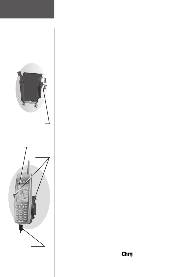
Section 2
Getting
Started
Tour
NavTalk Pilot Cradle with
Locking Assembly
NavTalk Pilot
in Cradle
Cradle Release
Tabs
Adapter Cord
14
To insert the NavTalk Pilot into the NavTalk
Pilot Cradle:
The NavTalk Pilot cradle secures the NavTalk Pilot in
place when not in use or when holding the unit is not
required. A locking assembly provides a secure mount to
prevent disengagement. Two hooks at the base of the
cradle provide for storage of the adapter cable when not
connected to the unit.
1. Insert the NavTalk Pilot in the cradle by guiding the
unit onto the two flanges on the base of the cradle
and then pivoting back while pushing down until it
clicks into place.
2. Slide the locking assembly up to secure the unit in
place. Slide the locking assembly down and then
press in on the two tabs on each side of the cradle
to remove the unit.
3. When removing the NavTalk Pilot from the aircraft,
place the adapter cable over the two hooks at the
bottom of the cradle for secure storage.
Charging the battery using the aircraft
adapter:
The aircraft adapter provides power to operate the
NavTalk Pilot whenever it is connected to the aircraft
adapter cord and aircraft power is turned on. Power is
switched from battery to the adapter and the battery is
fast charged (unless completely depleted, then a trickle
charge will begin to protect the battery from damage) and
when completely charged, a trickle charge will keep the
battery “topped off”. A safety feature terminates the fast
charge after three hours if the charging process has not
already completed. Fast charging is operational only if
the battery temperature is between 32 and 100 degrees F
and voltage limits are between 3.0 VDC and 6.0 VDC. If
fast charging is disallowed because of these factors, then
trickle charging begins. When the aircraft power is
turned off, charging will stop. When fast charging the
Battery Status icon will appear as a ( ). See page 19
for Power/Battery Status information.
Page 29
Section 2
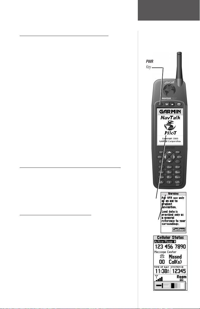
Turning the NavTalk Pilot On and Off
1. Press and hold the PWR key to turn the NavTalk
Pilot on.
2. Press and hold the PWR key to turn the NavTalk
Pilot off.
Each time the Navtalk Pilot is turned on, the
PWR
Key
Welcome Page will appear while the unit conducts a self
test. A Database Information Page and Warning Page
appear, asking you to read and acknowledge important
information regarding the proper use of the land data that
is provided.
After approximately ten seconds, the Land Data
Warning Page will be replaced by the Cellular Status Page.
Press the PAGE or ENTER key twice to bypass these
pages. (If the Satellite Status Page appears instead of the
Cellular Status Page, it’s because the unit was in the GPS
receiver mode when it was turned off.) Refer to page 61
for more information on initialization.
To Switch from the Cellular to GPS Modes
1. Press the GPS/PHONE Mode key. Toggle the key to
switch back and forth from GPS to Cellular.
At this point you may want to adjust the screen
contrast which you can do by selecting the GPS mode
Satellite Status Page or Cellular Mode Status Page.
To Adjust the Screen Contrast
1. Press the PAGE key until you access either the
Cellular Status page in the Phone Mode or the
Satellite Status Page in the GPS Mode. Press the
right arrow of the ARROW keypad. A pop up
sliding indicator will appear. To increase the
contrast, move the indicator to the right by pressing
the right arrow key.
2. To decrease the screen contrast, press the left arrow
of the ARROW keypad. Press the PAGE key to
finish.
Greeting
Page
Warning
Page
Contrast adjustment is also available from the Setup
Menu/System Page (see page 50.)
Getting
Started
Tour
Contrast Adjustment
15
Page 30
Section 2
Getting
Started
Tour
Zoom/Volume
Keys
Power Key/
Backlighting
Adjustment
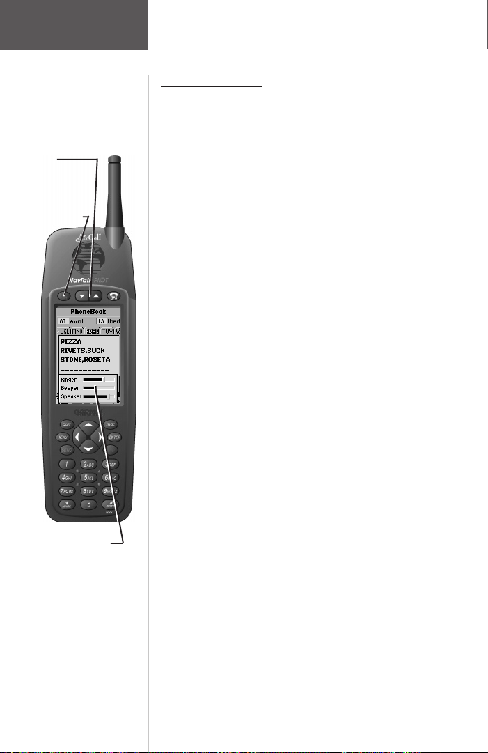
To Adjust Volume
The Zoom/Volume keys can be used to adjust the
ringer, beeper, and speaker volume on any page (other
than the GPS map and highway pages). Pressing these
keys will cause a pop-up menu to appear, showing sliding
indicators for each volume control. Each field must be
selected prior to changing volume settings.
1. Press a ZOOM/VOLUME key. When the pop-up
menu first appears the appropriate field is in edit
mode: beeper (no call), ringer (when phone is
ringing), and speaker (during a call).
2. Using the left and right arrow keys, move the
indicator to the left for less volume and to the right
for more volume.
3. To highlight a different field, use the up/down arrow
keys. Use left and right arrow keys to move the
indicator. Press QUIT to end or press no keys and
allow to time-out.
The volume levels are different when the unit is in the
airplane and car cradles. Volume is adjusted in the
appropriate cradle in exactly the same way, but can only
be done when in said cradle. When placed in the cradle,
the volume setting will return to the former level for that
cradle.
Volume Adjustment
Pop-Up
16
To Adjust Backlighting
The NavTalk Pilot’s three-level backlighting is
controlled with the PWR key and may be adjusted at any
time, from any page.
To turn the backlighting on:
1. Press PWR repeatedly until the backlighting is at
the desired level (off, 1, 2, or 3). Extended press of
the PWR key will shut the unit off.
Page 31

Section 2
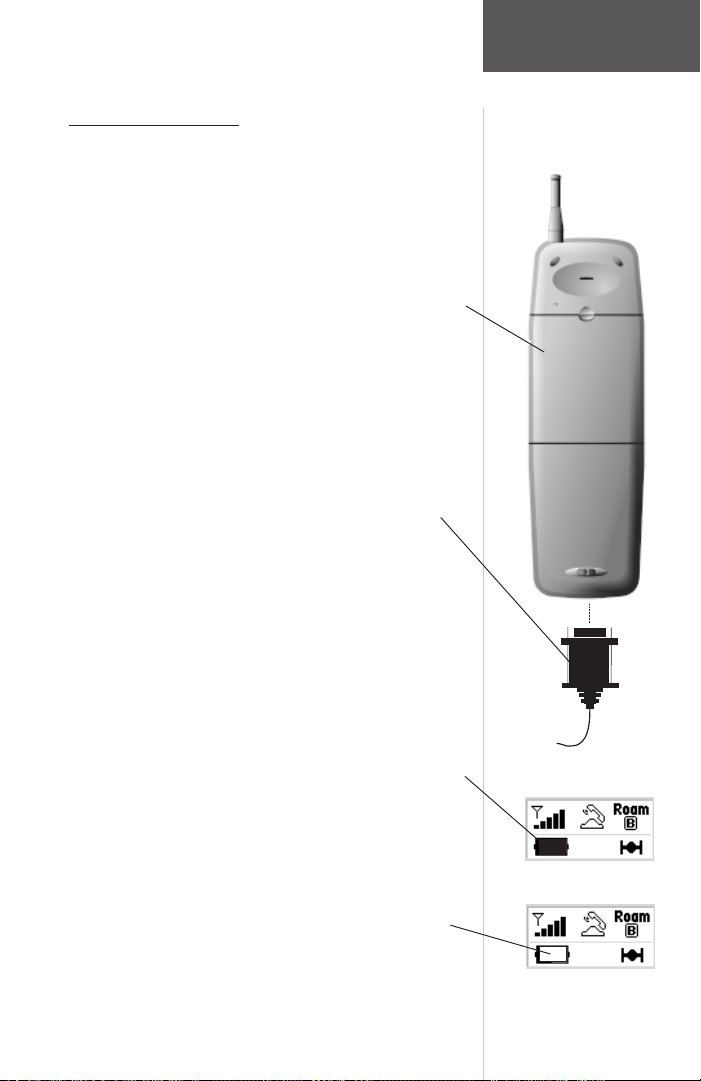
Understanding the Status Bar
An important feature of the NavTalk Pilot is the
combined GPS/Cellular Status Bar that appears at the
bottom of every main GPS and Cellular Page. The Status
Bar is important because it lets you know at a glance the
status of all the primary functions of your NavTalk Pilot.
The Status Bar appears in two sizes: large and regular.
The large size Status Bar is displayed only at the bottom
of the Cellular Status Page and is divided into two lines
(see figure below).
The top line is dedicated to providing cellular
information and conveys three main pieces of information:
• The Cellular Signal Strength - is indicated by an
antenna with 1 to 5 signal bars. The number of bars
shows the strength of the signal received by your NavTalk
Pilot. No bars means you may not be able to call.
The display will change as you move with your unit.
If the signal is not strong enough to place a call, try
moving to a different location.
• The phone “In Use” indicator (displayed
during placed or answered call) - this symbol appears
whenever you answer or place a phone call. When there
is no call activity this space is blank or replaced by the
Auto-Answer or Pager icon when these features are
selected as shown on page 18. When the microphone is
muted an “M” will appear next to the “In Use” icon.
Getting
Started
Tour
Status Bar at the base
of the Cellular Status
Page.
Signal Strength Icon
Phone “In-Use” Icon
17
Page 32

Section 2
Getting
Started
Tour
Auto-Answer Icon
Auto-Pager Icon
Auto-Data Icon for
Position Polling
Cell Phone Roaming
Status Icon
• The Answer Status Icons — You can program
the NavTalk Pilot to display the answering status of the
phone. When set to ‘Auto-Answer’ the phone will
automatically answer. When set to ‘Pager’ it will allow
callers to enter their phone number for returning their
call. When the ‘Auto-Data’ feature is active the Auto-Data
icon will appear when automatic position reporting is
taking place.
• The Roaming Status — (H means Home, A or B
means roaming A or B, and P means roaming on a
preferred SID).
The term “roaming” applies to the use of your
NavTalk Pilot within ground based cellular systems other
than those designated as your “home” system. As your
NavTalk Pilot begins to roam, it seeks service according to the
conditions you have selected. Contact your system operator,
or that of the visited system, for information on billing and
dialing services. When operating in the air cellular mode
roaming does not apply, as the air cellular system is
universal in coverage. You will switch from cell to cell as
you travel but it will not be acknowledged by the NavTalk
Pilot.
When the phone is not communicating with the
cellular system, either because the system is down or the
phone is out of range, the words “No Service” are
displayed on the top line in place of the indicators
described above. “Cellular Off” means the phone is off,
but allows access to all cellular pages. You cannot send or
receive calls with the exception of using Emergency
Calling (refer to page 57.)
When the phone is not operating properly the words
“Service Unit” are displayed on the top line and the phone
cannot be used for calls.
The bottom line provides some general purpose
information in addition to the current GPS status. Three
indicators are displayed:
18
Page 33

Section 2
• The Power/Battery Status — (battery gauge,
external plug-in or fast charge icon). The amount of
shading left in the battery icon shows the amount of
charge left in the battery pack. The more shading you
see, the greater the charge. When the battery pack is low,
the NavTalk Pilot alerts you in the following ways:
• ‘Empty icon’—No charge left.
• ‘Low Battery’ message will appear, followed by a
periodic short tone.
If you ignore these warnings, the NavTalk Pilot will
automatically turn itself off when the battery has a very
small charge left. Simply charge the battery to resume
normal operation. A two prong plug icon indicates that
you are using AC or DC power adapters. An automobile
icon will appear when using the GARMIN Vehicular
Adapter (Hands-Free) Kit. An airplane icon appears when
the NavTalk Pilot is secured in the cradle in the airplane.
• Backlight Icon — shows active backlighting.
• The GPS status — (solid satellite icon means
tracking satellites, flashing means searching
satellites, SIM means simulator, OFF means GPS
off). See the reference section for more information
on satellite acquisition.
The regular size version of the Status Bar uses the
same icons and text, except in a condensed size (see figure below).
Getting
Started
Tour
Battery Capacity Icon
Power Adapter Icon
Fast Charge Icon
Automobile Icon
Backlighting “ON” Icon
airplane Icon
Notice how the cellular portions of the regular Status
Bar have been reduced to fit, but directly reflect the look
and feel of the larger versions. The left half of the regular
Status Bar equates to the top line of the larger version and
the right half corresponds to the bottom line.
GPS Icon
19
Page 34

Section 2
Getting
Started
Tour
Menu Selections that
are specific to Phone
Functions are Timers,
Emergency and Setup
“Units” Settings
Sub-Menu
Main Menu Page
The Main Menu gives you access to the in-depth
programming and features of the cellular phone. The
pages are sub-menus that can be used to customize page
displays and make changes to system settings.
The Main Menu has three selections that are specific
to Cellular Phone use; Timers, Emergency and Setup.
To view the Main Menu:
1. Press MENU twice.
The Main Menu displays both GPS and Cellular
programming features. Basic phone function can be
performed without programming of the features accessed
in the Main Menu. These features are explained in
Section 4, “Cell Phone Reference” and Section 6, “GPS
Receiver Reference.”
To select Setup from the Main Menu:
1. Highlight “Setup” using the arrow keypad and press
ENTER.
The “Setup” option provides a list of settings for both
the GPS receiver and the cell phone (presented as a series
of file tabs). For a brief look at how the “Setup” option
works, change the units of measure for distance and
speed.
1. Highlight the “Units” tab using the ARROW keypad.
The “Units” settings are automatically displayed.
2. Highlight the “Distance & Speed” field using the
ARROW keypad, and press ENTER. A pop-up
menu appears showing the available options.
3. Select the desired option using the ARROW keypad,
and press ENTER.
4. To return to the Main Menu, press QUIT.
20
Page 35

Section 2
Cell Phone Pages
All of NavTalk Pilot’s cell phone menus and options
are accessible through the four main cell phone pages.
You can quickly scroll through the four pages in either
direction by repeatedly pressing the PAGE or QUIT keys.
Each of the cell phone pages are covered in detail in the
reference section, but for now let’s just briefly introduce
each page. The first cellular phone page is the Cellular
Status Page.
Cellular Status Page
The Cellular Status Page displays the following:
• Your active phone number, view of ground
number, view of air cellular number, time of
your last call, last dialed number, or the date
— (you can switch between the six by pressing
ENTER.)
• A message center — which gives you easy access
to a list of missed calls. Detailed information on
the message center is given in the reference section.
• Configurable Data Fields — These two data
fields can be changed by selecting ‘Change Fields’
from the cellular page menu. The fields can be
changed from ‘Time of Day’ and ‘System I.D.’ to
two of 37 options (see pages 37 and 38.)
• System Identification Number (SID) — The
numeric system ID for the cellular system the unit
is currently communicating with.
The Cellular System Page also displays a status bar
that was discussed on page 17.
There are two sub menu pages that are accessed from
the Cellular Status Page: the Missed Calls Page and the
Dialing Page. These two pages are discussed in detail on
pages 37 and 38.
Getting
Started
Tour
Configurable Fields
Incoming Call Message
Cellular Status Page
Displaying a Redial
Number, Call Timer and
“In-Use” Indicator
21
Page 36

Section 2
Getting
Started
Tour
Speed Dial Page with
Number 0 Selected.
Press SEND or hold the
ZERO Key for more
than 1 second to dial.
PhoneBook Page
• The PhoneBook Page gives you a handy way of
recording and storing names and phone numbers
for later use.
• The PhoneBook Page will hold up to 100 names in
alphabetical order in tabbed sections. Tabs and
names are selected using the ARROW keypad.
• The Spell’n Find feature allows you to select a name
and number from the PhoneBook quickly by
spelling the name starting with the first characters
of the name. This is particularly useful when your
Phonebook is nearly filled to capacity. Press MENU
with the PhoneBook page displayed to access.
Last Dialed Page
• The Last Dialed Page gives you a convenient way of
viewing and redialing the last nine phone numbers
dialed. To redial, highlight the number and press
SEND (see page 32.)
• Detailed information such as time of day and date is
provided.
• A scroll bar will appear as the list grows too big for
the page.
Speed Dial Page
• The Speed Dial Page gives you a handy way of
dialing numbers that you have listed on the page.
The page holds nine entries and an emergency
number.
• These numbers may be entered into the Speed Dial
Page list but will also become part of the listing in
your PhoneBook Page.
• To make a call using Speed Dial, hold the number
key corresponding to the name on the list for one
second. Or, use the ARROW keypad to highlight
the name or number you wish to call then press
SEND.
22
Page 37

Section 2
GPS Pages
All of the NavTalk Pilot’s GPS setup and options are
accessible through six main GPS pages. You can quickly
scroll through the six GPS pages in either direction using
the PAGE or QUIT keys. Let’s briefly look at each of
these pages in order to give you some insight into how
they help you navigate.
Satellite Status Page
Let’s start with the Satellite Status Page. If you’re not
already on this page, press PAGE or QUIT until it appears.
The Satellite Status Page shows you satellite status
information that helps you understand what the GPS
receiver is doing.
It features a sky view of available satellites, corresponding signal strength bars, the status of your current
position fix (acquiring, 2D, 3D, etc.), and your estimated
position error (EPE).
The Satellite Page and all other GPS main pages
display the Status Bar at the base of each page.
Position Page
The Position Page shows you where you are, what
direction you’re heading, and how fast you’re going.
A graphic compass at the top of the page shows your
direction of travel while you’re moving (your track), and
six user-selectable data fields below show your current
speed, average speed, trip odometer, trip timer, and
sunrise/sunset times at your current position.
“User-selectable” means you can change them to
display other information. These fields are covered in
more detail in the reference section. Below the userselectable data fields are additional data fields that display
your current position in latitude and longitude and
current time and date.
Getting
Started
Tour
Satellite Page
Position Page
23
Page 38

Section 2
24
Getting
Started
Tour
Map Page
HSI Page
Map Page
The Map Page shows your movement and surrounding detail (lakes, rivers, highways and towns). Your
present position is identified by an airplane icon in the
center of the map. You can use the Zoom/Volume keys to
adjust the map range (800 feet to 500 miles).
To change the map range:
1. Press the IN zoom key (down arrow) to select a
smaller range and more detail for a smaller area.
2. Press the OUT zoom key (up arrow) to select a
larger range and display a larger area.
Nearby waypoints are depicted on the map with any
one of over 40 different symbols, with the waypoint name
shown directly above the symbol. More about the
NavTalk Pilot’s waypoint features and the Map Page is
covered in the reference section, including how to change
the map orientation if you desire.
HSI Page
The NavTalk Pilot features two different navigation
pages: HSI (horizontal situation indicator) and Highway
page. The HSI Page is first.
The HSI Page provides graphic steering guidance to a
destination waypoint, with an emphasis on the bearing to
your destination and current direction of travel. (The
Highway page also provides graphic steering guidance by
displaying a three-dimensional perspective of your course
and the surrounding area.) The HSI graphically depicts a
mechanical HSI, showing the desired course using a
‘D-bar’ (course deviation bar; which is part of the course
deviation indicator, or ‘CDI’) and course pointer. If you
move off course, the D-bar will indicate off course
distance and direction. To return to the desired course,
simply steer in the direction of the D-bar until it returns
to the center of the CDI. The CDI scale is adjustable, with
the current scale indicated at the bottom of the page. The
scale setting represents the distance from the center of the
CDI to full left or right limits.
Page 39

Section 2
The HSI depicts your (ground) track heading using a
rotating ‘compass card’. Don’t confuse this with the
aircraft heading indicated on your panel. On a windy day
these two figures can differ significantly.
The HSI page also provides a TO/FROM indication
and vertical guidance, when using the unit’s vertical
navigation (VNAV) features. Four user-selectable data
fields indicate current speed, distance to destination, time
enroute and time of day.
Highway Page
Like the HSI Page, the Highway Page also provides
graphic steering guidance to a destination waypoint. You
can use the Highway Page instead of the HSI Page as your
primary navigation page when your main concern is
following a defined course.
Your present position is at the bottom center of the
highway display.
The line down the middle of the highway represents
your desired course. As you navigate toward a waypoint,
the highway will actually move—indicating the direction
you’re off course. To stay on course, simply move toward
the center of the highway.
The fields at the top left of the page show speed and
distance to your destination (or the next waypoint in a
route), along with a track compass showing current
direction of travel.
Across from the speed field is the time required to
reach your destination (or the next waypoint in a route),
in hours/minutes or minutes/seconds. The pointer shows
the bearing to your destination, relative to your current
track. If the pointer points straight ahead, you’re heading
directly to your destination.
Getting
Started
Tour
Highway Page
25
Page 40

Section 2
Getting
Started
Tour
Active Route Page
Active Route Page
The last of the six main GPS pages is the Active Route
Page. This page shows the GOTO waypoint or each
waypoint of a route, with waypoint name and the course
along each leg (segment) of the route.
When using a route, the current destination is
marked with an arrow on the left-hand side of the screen.
If no destination has been specified using the #/GOTO
key or a route, no waypoints will be listed on the page.
Messages
The NavTalk Pilot uses on-screen messages to alert
you to important information. Whenever a message
appears, press ENTER to acknowledge the message and
return to the previous page you were viewing. Refer to
Appendix D on pages 143-145 for a complete listing of
these messages.
“Pop-Up” Message
26
Page 41

Section 3
Section 3 - Table of Contents
Placing a Call ............................................................... 29
Answering a Call .......................................................... 29
Unsuccessful Call Attempts .......................................... 30
Dialing Errors .............................................................. 30
Auto-Redial .................................................................. 30
Ending a Call ............................................................... 30
Missed Call Indicator ................................................... 30
Using the PhoneBook................................................... 31
Speed Dialing ............................................................... 32
Last Dialed ................................................................... 32
Call Timers .................................................................. 33
Operating Modes ......................................................... 34
Basic Phone Operation
The first time you use your NavTalk Pilot Cellular
Phone you don’t need to be completely familiar with
every system feature to place and answer calls. Once your
Cellular Service Provider has programmed the phone
portion of the NavTalk Pilot for cellular use you can begin
using it.
Basic Phone
Operation
27
27
Page 42

Section 3
Basic Phone
Operation
Important!
Remember that a cellular
telephone is a radio that acts
like a telephone and that all
conversations on cell phones
are unprotected and can be
monitored.
There are laws that protect you
against eavesdropping (the
Electronic Communications
Privacy Act of 1986 makes it a
criminal offense to monitor
cellular phone calls) but you’ll
still want to be careful of what
you say on your NavTalk Pilot.
Antenna
Power
ON/OFF
Volume
Adjust
GPS/Phone
Mode Select
LCD Display
Screen
28
Arrow
Keypad
Send
Key
End
Key
Phone
Keypad
Emergency dial
Key
9
Page 43

Section 3
Placing a Call
To place a call:
1. Manually enter the phone number from any page
using the phone keypad and press SEND. The call
timer starts counting after you place the call.
2. From the PhoneBook Page highlight the name or
number you want dialed and press SEND. The call
timer starts counting after you place the call. Press
PAGE or QUIT to access the PhoneBook Page.
3. If the number is stored on the Speed Dial Page
simply press the phone keypad number that
corresponds to the phone numbers placed on the
Speed Dial list. Hold the key down for more than
one second to dial that number from any display on
the NavTalk Pilot.
Or...
Or...
Answering a Call
To answer a call:
1. Press SEND. An incoming call is indicated by a
ringing tone, and the ‘Call—Press SEND’ message
flashing on the display. Once answered, the call
timer starts counting.
If a call is not answered, the ‘Call—Press SEND’
message will continue flashing and the ringing tone will
continue until SEND is pressed. Pressing END will mute
the ringer for this call. When placing a call, wait for the
IN USE icon and the phone call should connect. If a
connection cannot be made, fail tones will sound.
Basic Phone
Operation
Manual Dialing Page
Call Notification
Unsuccessful Call Attempts
If you hear one of the following signals, you have not
successfully completed your call:
• Fast Busy The cellular system is busy. To
correct, press SEND again after ending the call, to
immediately redial the call, or press END and dial
the number later.
Cellular Status Display
when redialing a phone
number
29
Page 44

Section 3
Basic Phone
Operation
Important!
The NavTalk Pilot does
not have an extendible
antenna. Hold the phone
as you would any other
telephone. While speaking
into the mouthpiece,
position the antenna up
and over your shoulder.
Do not hold the antenna
or allow it to come into
contact with any other
object while making a call
or while talking. This can
affect call quality.
• Alternating High/Low Tone The cellular system
could not complete the call. You may have tried to
place a call before the NavTalk Pilot was fully
operative or poor signal strength is preventing the
celluar system from receiving the NavTalk Pilot
signal. To correct, press SEND to immediately redial
the call, or press END and dial the number again.
• Busy signal The called party’s phone is busy.
Dialing Errors
If you make an error while entering a phone number
press the left arrow key of the arrow keypad to delete the
last number. To delete the entire entry, press and hold the
left arrow key of the arrow keypad or END. Now you can
re-enter the number you want to call.
Auto-Redial
The phone features ‘Auto-Redial’ which makes it
possible for you to repeat call attempts when the cellular
system is busy. If you receive an alternating high/low
signal or the fast busy tone when attempting to place a
call and wish to retry the call you can program the phone
to redial the number. The phone recognizes that the call
was not completed, then it redials every 15 seconds. You
can program this feature to redial up to nine times. If you
do not want automatic redialing, press END at any time.
‘Auto-Redial’ is programmed in the Phone setup page
accessed from the Setup portion of the Main Menu. See
page 41 for information.
30
Ending a Call
To end a call Press END.
Missed Calls Indicator
The NavTalk Pilot counts up to 20 unanswered and
Auto Pager calls. The number of missed calls are
displayed below the telephone icon located in the message
center on the Cellular Status Page.
Page 45

Section 3
To view the Missed Calls List:
1. Highlight the Message Center phone icon and press
ENTER to view the list of missed calls. There are
three types of listings:
No Answer Time/date stamp. Not answered,
manually, by auto-answer or by Auto-pager.
No Message Time/date stamp. Answered by
Auto-pager, but no message is left.
Phone Number Time/date stamp. Answered by
Auto-pager and DTMF tones for number entered.
To return a call with a phone number:
1. Highlight a selected missed call phone number and
press SEND to call that number.
Using the PhoneBook
The PhoneBook is your repository for all recorded
names and phone numbers. It can store up to 100
numbers.
To View the PhoneBook Page:
1. Access the PhoneBook Page by pressing the PAG E
key until the PhoneBook page is accessed.
2. Use the left or right arrow keys to move from tab to
tab through the PhoneBook and the up/down keys
to highlight the name you want to call.
3. Press the SEND key and your call will be placed.
4. The phone number dialed will be placed in the ‘Last
Dialed’ directory even if the call is not answered.
You can set the ‘Auto-Redial’ feature to continue
calling the number for up to 9 tries if the cellular
system is busy. Refer to the section on Auto-Redial,
page 41.
5. To enter names into the PhoneBook directory press
the MENU key after you have accessed the
PhoneBook page. Information on programming
phone numbers is contained on page 39 of the
Cellular Phone Reference section.
Basic Phone
Operation
Missed Calls Indicator
Missed Calls List
PhoneBook Page
with Index Tabs
31
Page 46

Section 3
Basic Phone
Operation
Enter Names into the
PhoneBook Using ‘New
PhoneBk #’. Find a
Name Quickly by Using
‘Spell ‘n Find’
Enter this Number
to Speed Dial from
anywhere on the
NavTalk Pilot
Speed Dialing
The Speed Dial feature allows you to store up to nine
phone numbers from your PhoneBook directory for quick
access for dialing.
1. To access the Speed Dial page, use the PAGE key to
scroll through the pages until you reach Speed Dial.
2. If you know the list number of a name on the page,
press the keypad key with that number for more
than one second to Speed dial from any display on
the NavTalk Pilot.
3. You can also highlight a name and press SEND to
dial in a conventional manner.
Speed Dialing is programmed when you enter a name
and number into the PhoneBook at the New Number
programming page. For information on entering new
numbers, refer to page 42 in the Cellular Phone Reference
section.
Last Dialed
The Last Dialed feature automatically stores up to
nine phone numbers you have previously dialed for quick
access for redialing.
1. To access the Last Dialed page, use the PAGE key to
scroll through the pages until you reach the Last
Dialed Page.
2. Use the ARROW keypad to highlight the name you
want to call again. Beneath each name is the date
and time that you last placed a call to that person.
3. Once you have highlighted the name, press SEND
and the call will be placed, and the date and time
will automatically be updated.
32
Page 47

Section 3
The Last Dialed Page will display a scroll bar when
more names than can be displayed are listed on the page.
Whenever you place a call, the number is added to the
page and the oldest last dialed name or number is deleted
from the list whenever the page is filled with a maximum
of nine numbers. You can edit entries on this page by
pressing
MENU
to add a number to the PhoneBook,
remove it from the list, etc.
Call Timers
Call Timers are useful for recording the amount of
time of your last call, the total elapsed time for all calls
during a measured period of time, and the total lifetime
use of your NavTalk Pilot. You can also set the NavTalk
Pilot to signal each time a minute of your current call has
elapsed. It beeps at 50 seconds into the first minute and at
one minute intervals thereafter to help you save on
minute increment call billing. Last Call and Elapsed Time
are always active and can be reset through the Call Timers
function of the Main Menu.
1. Access the Main Menu by pressing the MENU key twice.
2. Scroll down to Timers and press ENTER to view
the timers page. On this page use the ARROW
keypad to move to the ‘Calls’ tab.
3. To reset the Last Call, Elapsed timers and turn the
Minute Timer on or off, highlight the selection and
press ENTER.
Refer to page 51 of the Phone Reference Section. The
Lifetime timer cannot be reset.
Basic Phone
Operation
Last Dialed Name with
Time/Date Stamp
Last Dialed Edit Page
The Minute Timer
signals with 2 Short
Beeps every 60 Seconds
which cannot be heard
by other parties.
33
Page 48

Section 3
Basic Phone
Operation
Operating Modes
The NavTalk Pilot automatically selects between
airborne and ground modes based on docking (cradle)
status. Under certain conditions, the cellular transceiver
is disabled to prevent interference to both the airborne
cellular and conventional cellular networks. The table
below indicates the unit operating mode as it applies to
ground speed and cradle docking.
Mode Docking GPS Velocity Cellular Operation
Ground Undocked < 100 mph Conventional
Undocked
Undocked Undefined Conventional
Airborne Docked < 20 mph Off
Docked
Docked Undefined AirCell
³
100 mph Off
³
20 mph AirCell
34
Page 49

Section 4
Section 4 - Table of Contents
Introduction ................................................................ 37
Fields in the Cellular Status Page .................................. 37
Programming Cellular Status Page Fields ..................... 38
Changing Ringer, Beeper and Speaker Volume ............. 39
Using the PhoneBook................................................... 39
Redialing Numbers Previously Called Using the Last
Dialed Page ............................................................... 41
Redialing Using the Auto Redial Feature ...................... 41
Using the Speed Dial Feature ....................................... 41
Setting Up NavTalk Pilot Phone Features ..................... 42
Programming Phone Setup .......................................... 43
Programming Security to Lock the Phone and Selected
Features .................................................................... 45
Selecting an Active NAM .............................................. 47
Scanning for Cellular Service ....................................... 48
Setting Sound Functions for the NavTalk Pilot Cell Phone
Features .................................................................... 49
Setting Date and Time .................................................. 49
Setting Backlighting Interval, Contrast, Power Saver &
Remote Command .................................................... 50
Setting Call Timers ....................................................... 51
Missed Calls List Features ............................................ 52
Setting Up Dial String Codes for Automated Phone
Services .................................................................... 53
Using Prefix Dialing ..................................................... 55
Using Hook Flash ........................................................ 55
DTMF GPS Location Reporting .................................... 56
Programming Emergency Auto-Dialing ........................ 57
Cell Phone
Reference
Cell Phone Reference
This section provides in-depth information on all of
the NavTalk Pilot’s advanced Cell Phone functions and
features.
35
35
Page 50

Section 4
Cell Phone
Reference
Antenna
Power
ON/OFF
Volume
Adjust
GPS/Phone
Mode Switch
LCD
Display Screen
Menu
Key
(Access to
Feature Options)
Arrow
Keypad
(Cursor and Data
Entry)
36
Enter
Key
(Selects Fields
and Options)
Send
Key
End
Key
Phone
Keypad
(Dialing and
Data Entry)
Emergency Dial
Key
9
Page 51

Section 4
Introduction:
The NavTalk Pilot Cell Phone provides you with a full
range of cell phone features as well as some unique to a
GPS/Cell Phone device. This reference section will
instruct you in how to use these features to enhance the
efficiency of the cell phone. Section 3 of this manual
titled, “Basic Phone Operation,” has provided you with
information on basic operation of the cell phone such as
placing and answering calls, adjusting volume, the cell
phone pages, auto-redial and missed call indicators. Now
you will learn how to take advantage of NavTalk Pilot’s
advanced cell phone features.
Fields in the Cellular Status Page
The Cellular Status Page will be the page most often
displayed during cell phone use. The fields displayed are:
Your Active Phone Number, Ground Phone
Number, Air Phone Number, the Duration of Your
Last Call, the Last Dialed number or the Date.
The Message Center
Two Configurable Data Fields — default to Cellular
System Identification Number and Time of Day
The Status Bar Symbols — which are explained in
detail beginning on page 17.
There are three sub-menu pages accessed from the
Cellular Status Page:
Missed Calls Page— Appears when you highlight
Message Center and press ENTER to display a list of
unanswered calls with numbers and date/time stamp.
Cellular Page Menu— Allows you to enter a
PhoneBook Number, use Spell n’ Find, Start/Stop
Cellular, select from Manual Answer, Auto Answer or
Auto Pager, Change Data Fields and to reset the page to
default settings.
Cell Phone
Reference
Cellular Status Page
Missed Calls Page
37
Page 52

Section 4
Cell Phone
Reference
Manual Dial Display
verifies dialed number
Select ‘Active Phone #’,
‘Ground Phone #’, ‘Air
Phone #’, ‘Last Call’,
‘Last Dialed’ or ‘Date’
Dialing Page— Appears when you dial a phone
number manually, when using the PhoneBook, Speed Dial
or answering a call.
The Dialing Page Menu— Allows new PhoneBook
entry, Spell ‘n Find, Manual, Auto Answer, Auto Pager,
Send Location, and Query Location.
Programming Cellular Status Page Fields
To view the Active phone Number, Ground
Phone Number, Air Phone Number, time of
last call, last dialed number or the date:
1. Highlight the first field on the Cellular status Page
and press ENTER. Then make your selection from
the pop-up menu and press ENTER. The Cellular
Status page will reappear with the phone number,
time, or date as selected.
To change the data displayed in the two data
fields:
1. Press MENU to access the page menu and select
‘Change Fields’. Then choose two from the thirtyseven data options available.
To add or find a number in the PhoneBook
and select the type of call answering:
1. Press MENU to access the Cellular Status page
menu.
2. Scroll to the feature you want to program and press
ENTER. If you selected ‘New PhoneBk#’ or ‘Spell ‘n
Find’ a new page will appear. If you selected
Manual Answer, Auto Answer or Auto Pager, press
ENTER to activate these features. Refer to page 41
for more information. ’Stop or Start Cellular’ allows
turning On or Off the cellular feature while still
having access to the Phone data pages, Emergency
Calling and GPS Receiver.
Cellular Status Page Menu.
Manual Answer currently
selected, indicated by light
gray shading.
38
Page 53

Section 4
Changing the Ringer, Beeper and Speaker
Volume Settings:
To change the volume settings:
1. From any page, press either of the ZOOM/VOLUME
keys at the top of the display window. The volume
control window will open at the lower part of the
display screen.
2. Then use the up/down arrow keys to scroll to the
control you want to change, then the left/right keys
to move the control bar to increase or decrease the
volume. The volume display will close five seconds
after the last keystroke.
Using the PhoneBook
The PhoneBook is your repository for up to 100
phone numbers arranged in alphabetical order with tabs
that group names in categories matching the alphanumeric keys on your keypad. You can quickly select a
tab by pressing the right/left ARROW keys and then
scrolling down to a listed name and number. To view all
data for a name, press ENTER and the ‘Edit Number’
display will appear. A category identified as ‘Other’ can
be used to hold notes and temporary phone numbers
recorded during phone conversations. The ‘Other’
category will store entries that begin with a numeral or
other non-alpha characters only.
To dial a number using the PhoneBook:
1. Highlight the name of the person to be called and
press SEND. The name and phone number of the
person you are calling will appear on the Cellular
Status page and the ‘In Use’ icon will appear in the
Status Bar.
Add or delete names and numbers from the
PhoneBook by pressing MENU once you have accessed
the PhoneBook and selected a name.
Cell Phone
Reference
Volume Control Panel
with Control Bar
Indicator
PhoneBook List and Phone
Number Information Page
New Phone Number
Option
39
Page 54

Section 4
Cell Phone
Reference
Name and Phone No.
entry in the PhoneBook
You are always prompted
before a deletion is
performed anywhere in
the NavTalk Pilot
Programming.
To enter a new number in the PhoneBook:
1. Access the PhoneBook page and press MENU to
bring up the PhoneBook Menu.
2. Highlight ‘New PhoneBk #’ and press ENTER, to
bring up the PhoneBook entry page. Press ENTER
to begin entry and then use the phone keypad to
enter the name. The character block moves to the
next position when you pause after entry. Use the 1
key to enter spaces and a comma or the 0 key for
this and other punctuation. Press ENTER when
finished and cursor down to the number field.
3. Enter the phone number using the phone keypad.
This field automatically spaces the dial string. To
quickly remove an entry in either the name or
number field, hold down the left arrow key with the
field highlighted after pressing ENTER. Move to
the Speed Dial field, press ENTER and assign a
Speed Dial number if desired. Then cursor to ‘Done’
and press ENTER to complete the entry.
To remove a name from the PhoneBook:
1. Highlight ‘Delete Number’ and press ENTER. You
will be prompted to confirm the deletion before
pressing ENTER to remove.
2. To clear the PhoneBook of all names, highlight
‘Delete All’ and press ENTER. You will be prompted
to confirm this deletion before pressing ENTER to
remove all names from your directory.
You can use the Spell ‘n Find feature to quickly find a
name in the phonebook without scrolling through the
name lists. Access the PhoneBook, select Menu and
cursor down to ‘Spell N’ Find’. Then spell out the first
part of the name you want to find until it appears on the
display, and press SEND.
40
Page 55

Section 4
Redialing Numbers Previously Called Using
the Last Dialed Page
You may often need to speak with the same person
throughout the day or may not have made contact with
that person when you last dialed their number. By
accessing the Last Dialed Page you can recall from the list
of last dialed numbers those that you would like to redial.
The list will retain the last nine dialed numbers from the
PhoneBook and manually dialed numbers. A scroll bar
will appear when there are more numbers than can be
displayed. Highlight the name or number and press
SEND to redial.
Redialing Using the Auto-Redial Feature
You can automatically redial a phone number when
the cellular cannot be accessed because of system traffic,
poor signal, etc. You can auto-redial the number up to
nine times. This feature is programmed from the Phone
Page of the Setup Program. It will not redial a busy
number or an unanswered call (refer to Page 43-44.)
Using the Speed Dial Feature
The Speed Dial Feature allows you to view name or
Phone Keypad number assignments, and hold the
number key corresponding to the Speed Dial List number
for more than one second to dial that phone number from
anywhere on the unit. There are nine entry spaces on the
Speed Dial list. Names and numbers may be added to the
Speed Dial list when they are recorded using the ‘New
PhoneBk #’ menu. They can also be added from the
existing list of names in the PhoneBook by using the ‘Edit’
feature to assign a name to a Speed Dial position.
Cell Phone
Reference
When a number from the
Last Dialed List is
redialed, it moves to the
top of the list with a new
Time/Date Stamp.
When using AutoRedial, select the number
of times (up to 9) for
redialing a number.
41
Page 56

Section 4
Cell Phone
Reference
Speed Dial Assignment
There are only nine
positions on the Speed
Dial List. Be sure to
select an unused position
or a Speed Dial number
you want to overwrite.
Highlight Setup on the
Main Menu. Press
ENTER to access the
Setup pages.
To enter new names and numbers on the
Speed Dial Page:
1. Use the PAGE button to acquire the PhoneBook
page. Then press MENU to enter a new name and
number or edit an existing entry.
2. Highlight the desired entry from the PhoneBook and
press ENTER. If entering a new name and number,
press MENU instead of ENTER to bring up a ‘New
PhoneBk#’ display.
3. Enter the name and number and select a position
on the Speed Dial list that is unused, then highlight
‘Done’ and press ENTER. When you select a
position that is already assigned (0 through 8) it will
replace the old selection.
Setting Up NavTalk Pilot Phone Features
Access the Setup pages through the Main Menu by
pressing the Menu button and using the ARROW keypad
to scroll down to Menu Setup. Press ENTER to access
the Setup pages. These pages are selected by tabs at the
top of the screen. Use the right/left arrow keys to scroll
from tab to tab.
There are several conventions for moving from field
to field and making entries in each setup directory.
To setup phone features:
1. Use the ARROW keypad to move up, down and
from side to side to cursor to and highlight a
selected field.
2. Press ENTER to begin data entry, to “Pop Up” a
sub-menu or activate a button or icon.
3. Enter data using the phone keypad to enter
alphanumeric characters or cursor to a selection
from a pop up menu.
4. Press ENTER to store data and programming
selections for each field and then cursor to the next
field.
Start with the first tab page titled, ‘Phone.’
42
Page 57

Section 4
Programming Phone Setup (Answer Mode,
Auto Redial, Auto Data and Calling Card PIN)
There are three Answer Mode options, Manual Answer,
Auto Answer (Hands-Free, for headsets) and Auto Pager.
When Auto Pager answers, the microphone is muted and
the unit emits a beep tone to indicate the Auto Pager feature
is active. The caller then enters their phone number that is
placed in the ‘Missed Calls’ list along with a date/time
stamp. Inform frequent callers about the Auto Pager beep
tone signal. Pressing SEND pre-empts Auto Pager.
Pressing END before answering any call cancels Auto
Answer or Auto Pager. These two modes then resume for
subsequent calls. Auto Redial allows you to redial the
number you are calling up to nine times.
Auto Data provides for location data transmission
without ringing the phone or requiring the SEND key to
be pressed, and without displaying messages about
location transfer. If data is not detected within three
seconds, the call will ring for up to 50 seconds and is
treated according to user selection (Auto Answer, Auto
Pager or Manual Answer). Auto Data selection can be
locked and unlocked using the Security Password.
To program Answer Mode:
1. Use the down arrow key to highlight the field.
2. Press ENTER to display Manual Answer, Auto-
Answer or Auto-Pager from the pop-up menu.
3. If choosing Auto Answer or Auto Pager, press the
right arrow key to move to the Number of Rings
field, press ENTER and then use the up arrow key
or phone keypad to enter the number of rings. You
are limited to nine rings. Press ENTER to store your
selection.
Cell Phone
Reference
Highlight ‘Answer Mode”
and press ENTER to
display the pop-up
Options Menu for phone
answering modes.
Highlight the desired
option and press ENTER.
The Auto Data and PIN
selection fields require
unlocking, using the
Security Password
43
Page 58

Section 4
Cell Phone
Reference
Phone Set-Up Directory
programmed for AutoPager after 2 Rings and
Auto-Redial turned Off
The Auto-Data switch can
be turned On or Off using
the Security Password
Padlock icon open and
PIN field open for PIN
entry. After entry, close
padlock icon and the field
will be closed to viewing.
44
To program Auto-Redial:
1. Use the ARROW keypad to highlight the On/Off
field and press ENTER.
2. Highlight On or Off and press ENTER.
3. If you selected On, move to the Number of Times field
and press ENTER. Use the ARROW or phone keypad
to set the number of times you would like to redial any
given number (the maximum is nine), then press
ENTER. A “Redial” prompt will appear when active.
To program Auto Data:
1. Highlight the padlock icon and press ENTER. A pop
up window will appear at the base of the display.
Press ENTER to key in your password. After you
have keyed in the password press ENTER and
observe that the icon is now open and a PIN
window appears at the base of the display.
2. Use the ARROW keypad to highlight the ‘Auto
Data’ field and then press the ENTER key. To
secure repeat Step 1.
To enter your Calling Card Access PIN into the
phone programming:
To automate calling card dialing you can store your
PIN number in the unit for entry into a dialing string as a
code “C” as explained on pages 53 through 54. Your PIN
is password protected. Refer to “Security” page 45.
1. Repeat the steps above for programming Auto Data.
2. Move to the PIN field and enter your PIN, then press
ENTER.
3. Cursor back to the icon and press ENTER. Press
ENTER again when the password window appears.
Enter your password and then press ENTER. The
lock icon will close and your displayed PIN will be
hidden, but can be inserted in a call dial string by
using the “C” code (see page 54.)
Page 59

Section 4
Programming Security to Lock the Phone and
Selected Features
Lock Phone— To prevent unauthorized use of your
phone, you can lock it so that before you use it again you
must enter a lock password.
Auto Lock— To prevent unauthorized use of your
phone, you can set it to lock each time it is powered up
and the lock password or security password must be
entered before the phone can be used. This setting, when
checked, also allows ‘Quick Lock’ of the phone by using
the ‘Lock Phone’ button on this page or by holding the
Menu key from any page. When using ‘Quick Lock’ no
password is required to lock the phone.
Call Blocking— When you enable this feature you
can choose to exclude calls from these sources: All
Incoming, All Outgoing, Less than 11 Digits, 1 Prefix and
011 Prefix.
About Passwords:
The NavTalk Pilot employs two types of passwords
(actually number codes are created using the phone keypad
to spell words) to secure use of the unit and its stored data.
It can be programmed so that a Lock Password can be
used to Lock or Unlock the Phone.
Stored Setup data and the Lock Password are
protected by a Security Password. It secures settings
such as Calling Card PIN, Auto Lock, Call Blocking, NAM
Selection, Emergency Number, Remote Command and
Scanning features. The Security Password can also be
used to Lock or Unlock the phone.
NavTalk Pilot features that can be security protected
are accompanied by a padlock icon. The icon is closed by
default on each power cycle and can be opened by
highlighting and entering the Security Password.
Each password is provided with a default:
Lock Password = 1234
Security Password = 1234567
Cell Phone
Reference
Setup Menu Security
Directory
Password Programming
Page for Lock Password
‘Locked Phone’ Displays
after power ON. Enter
Lock or Security
Password to Unlock.
45
Page 60

Section 4
Cell Phone
Reference
Password Programming for Lock and
Security Passwords
Auto Lock Selected.
Enter Security Password
to secure Auto Lock and
Call Blocking
To program Lock and Security Passwords:
1. Highlight the ‘Change Password’ field and press
ENTER. A ‘Change Password’ window will appear.
2. Press ENTER and choose ‘Security’ from the pop up
menu, then cursor to the Security Field.
3. If you are entering a password for the first time,
move to the Security field and enter the security
password (if you haven’t created a security
password enter 1234567).
4. Press ENTER and cursor to the ‘New’ field to enter
your new security password. The password must be
from one to eight characters and entered from the
phone keypad.
5. Press ENTER to move down to the ‘Retype’ field
and re-enter the password. Press ENTER to record.
If the entry numbers, disguised by asterisks
disappears, your password has been changed. If
not, enter again.
6. Repeat this process for the ‘Lock’ password.
7. Press QUIT to return to the security Setup page.
You can program the NavTalk Pilot to lock automatically each time you turn it On. Whenever you encounter
a feature with a Padlock icon you must always enter the
security password to access or change any programming.
To use Auto Lock:
1. In the Security directory highlight the Padlock Icon
in the Auto Lock field and press ENTER to pop up
the security password box. Press ENTER again to
key in the Security Password.
2. Press ENTER to return to the ‘Auto Lock’ field. The
Padlock icon will be open and highlighted. Cursor
to the ‘Auto Lock’ box and press ENTER to activate
the Auto Lock feature.
3. Cursor back to the Padlock icon and press ENTER
to pop up the security password box. Re-enter the
password and press ENTER to return to the Auto
Lock field with the icon in the locked position.
46
Page 61

Section 4
To program Call Blocking:
1. Highlight the padlock icon in the ‘Auto Lock’ field
and press ENTER to bring up the Password
window.
2. Press ENTER to enter your password using the
phone keypad.
3. Press ENTER to unlock the icon.
4. Move down the list of call blockers and press
ENTER to activate blocking for those you have
selected.
5. Cursor back to the icon and press ENTER to re-
enter the password in the password window. Then
press ENTER.
Selecting an Active NAM
In addition to the preprogrammed AirCell Number
Assignment Module (NAM), you can store two ground
based cellular numbers in the NavTalk Pilot. This page
displays your Active NAM, the Phone Number for that
NAM, the Home System ID, Side A or B and Electronic
Serial Number (ESN). To select the phone number that is
appropriate for the area you are in, highlight the Active
NAM field, press ENTER and then select NAM #1 or #2.
The NAM #3 is reserved for AirCell NAM which can only
be used in the aircraft cradle. Therefore, this NAM is
automatically selected and displayed on this page when in
the cradle. The unit will automatically revert to the last
selected ground NAM (#1 or #2) when removed from the
cradle.
You can use the NAM page to select which phone
number is appropriate for the area you are in. NAM
programming must be done by your cellular service
provider when you contract for service. This page is
protected by a security password.
Cell Phone
Reference
Programming Call
Blocking
Secured NAM selection.
Enter Security Password
to unlock and change to
NAM #2.
47
Page 62

Section 4
Cell Phone
Reference
Secured Scanning Page
information is programmable to meet your
roaming requirements
Scanning for Cellular Service
The scanning feature allows you to access cellular
service in the order and selection made on this page.
Select Home to scan for your Home system first. You can
enter SID’s to the Preferred SID list and scan for those
numbers next. If you select A then B, the phone will scan
for a Side A system first, then for a Side B system. You
can choose any combination of A/B Side scanning. The
Preferred SID List holds the SID’s that you have selected
which will be scanned when you check the Preferred List
box. The Status Bar at the base of the display indicates
which type of service is active. Home = H, Preferred SID’s
= P, Side A Systems = A and Side B Systems = B. Emergency calling will override scan settings and use any
available system. Scanning may be necessary for air
cellular use and should remain active in case a non-home
SID is in use. Scanning selections for the AIR and NAM
are set at the factory and cannot be changed while using
this setup page. The status bar will always show “Home”
for AIR use, even when using the non-home SID.
To access scanning preferences:
1. Highlight the padlock symbol and press ENTER.
2. Enter your password using the phone keypad and
press ENTER.
3. Scroll through the Home, Preferred List and system
preference boxes and check those that you desire to
scan. The preferred SID List can hold up to 15
entries per NAM programmed by you or your service
provider.
The home system depends on the current NAM
selection. Contact your cellular service provider for
information about their roaming agreements with other
companies. In some areas, scanning phones are
automatically recognized by cellular systems with a
roaming agreement. In others, you must contact the
cellular provider before they can recognize your phone.
48
Page 63

Section 4
They will require your phone number and ESN number
(found on the NAM page of the setup menu). For
customer service regarding the AirCell NAM call AirCell at
1-888-286-9876.
Setting Sound Functions for the NavTalk Pilot
Cell Phone Features
By scrolling through the Sound Page you can set the
following sound features:
Microphone to Open or Mute during a call, Call Ring
to Ring A, Ring B, Ring C, Ring D, Ring E, or Off, and
Beeps to sound for Message and Key or only Message, or
Key only, or Off for no Beeps.
When Call Ring is Off, a message with beeps indicates
an incoming call. For total silence the ‘Beeps’ must also
be set to Off. The microphone setting cannot be changed
unless there is a call in progress. The microphone can be
muted during a call by holding the QUIT key. The three
volume settings can be set by pressing the ZOOM/
VOLUME keys at the top of the display screen anytime
(with exception of the map page where Zoom is
functional).
If you are using the NavTalk Pilot unit with the
GARMIN Vehicular Adapter (Hands-Free) Kit, you can
adjust the ‘External Mic Gain’ by highlighting that field
and using the ARROW keypad left/right keys to raise or
lower the gain as required, for both aircraft and auto.
Cell Phone
Reference
“Pop-up” menus
appear for each of the
Sound Page fields.
The ‘External Mic Gain’
feature is used with the
Aircraft and Ground
Vehicular Adapter Kit
Setting Date and Time
Date and Time are calculated directly from satellite
signals and cannot be changed. The Time and Date
settings are shown on Last Dialed and Missed Calls Lists
and on the GPS Position Page. The current time is
displayed on the Cellular Status Page. Refer to the GPS
Reference Section for time options.
The local time setting
is adjusted on the
Time Tab Page
49
Page 64

Section 4
Cell Phone
Reference
Remote Command can
be enabled or disabled
and is protected by a
security password.
Setting Backlighting Interval, Contrast, Power
Saver, and Remote Command
Control of backlighting is accomplished on the
System page along with Contrast adjustment and the
Power Saver feature. Backlighting is important to efficient
phone use at certain times of the day, such as early
morning, late evening and at night. It is recommended
that backlighting be set for ‘Always On’ when powered by
external power sources such as AC or DC adapters and
chargers.
Otherwise when operating on battery power, set for
the time normally required for dialing or other phone
functions that you normally use. When set for a specific
time, backlighting will auto cancel at the expiration of the
time set, which begins after the last key press, but will
turn back on when an incoming call rings-in or any
button on the unit is pressed.
Extensive use of backlighting will cause a significant
reduction in battery life when powering the unit from the
batteries only. Enabling the ‘Always On’ backlighting
setting during charging will significantly lengthen
charging time.
About Remote Command:
Remote Command is a feature that allows your
NavTalk Pilot be be remotely queried for location by
another NavTalk Pilot, or another DTMF capable device
(i.e., a PC Modem). This can only take place during an
“Active” cellular call. Remote Command can be ‘Enabled’
or ‘Disabled’ according to the privacy that you desire.
When ‘Enabled’ the unit will respond to any DTMF tones
to “Transfer Location” while in a call. If ‘Disabled’ it will
not respond to these Tones. Remote Command is
password protected to prevent unauthorized changing of
the current setting.
50
Page 65

Section 4
To enable Remote Command:
1. Press the MENU key twice to access the Main
Menu.
2. Cursor to the Setup Menu option and press ENTER.
3. Select the System Setup Page tab, then cursor down
to the padlock icon above the ‘Remote Command’
field.
4. If the icon is locked, highlight it and press ENTER to
pop up the Security window. Enter your Lock Code
to open the lock. If the icon is not locked cursor to
the ‘Remote Command’ field and press ENTER to
enable or disable this feature.
To “Query” for a GPS location:
1. Dial the number of a NavTalk Pilot unit or similarly
programmed cellular device. When the called
number answers press MENU and cursor to ‘Query
Location’ and press ENTER. You will hear the
DTMF tones and the “Transferring Location”
message will appear.
2. When the DTMF tone has been recognized, the
other unit will transmit the GPS location to your
unit, but only if it has the ‘Remote Command’
feature enabled. If it is not, the tones will stop and
the new position will not be acknowledged. If the
call is disconnected before the transfer is complete,
the new position will not be acknowledged.
3. The new position is acknowledged by a confirmation message and the location marked as a “Phone”
waypoint on the Map Page. Refer to Page 56 for
more information.
Cell Phone
Reference
The Minute Reminder
will emit two beeps each
minute unless turned Off
Setting Call Timers
Call Timers are useful for recording the time of the
last call you made, the elapsed time of all calls for a
measured time period, and the total lifetime use of your
NavTalk Pilot call time. You can also set the unit to signal
each time a minute of your current call has elapsed.
51
Page 66

Section 4
Cell Phone
Reference
Missed Calls Icon
Missed Calls list
Menu entries ‘Mark As
Old’, ‘Mark As New’, and
‘Remove Entry’.
52
Call timers for Last Call and Elapsed Time are always
active and can be reset through the Call Timer function of
the Main Menu. Lifetime use timing cannot be reset.
The Minute Timer can be turned On or Off through
the Call Timers function of the Main Menu. The first
timed minute will beep at 50 seconds into the call and
every minute thereafter in order to allow you to end the
call prior to a full minute to help reduce minute charges.
Missed Calls List Features:
Because the Missed Calls list can display the phone
numbers of calls received when you have enabled the
Auto Pager feature you may want to manage this list to
keep a record of returned calls.
To mark calls as old, or remove an entry:
1. Access the Phone page by pressing the PAGE key
repeatedly.
2. Scroll to the Missed Call icon and press ENTER. The
Missed Calls Page will display the list of calls in the
order in which they were received. The list will state
“No Answer” and the time/date for each call that
was missed. If you had enabled the ‘Auto Pager’
feature and the caller entered their number, then
that number or “No Message”, if no numbers were
entered, will appear on your list.
3. To be certain you have returned the missed calls,
you can mark a missed call as old or remove it from
your list.
4. Access the Cellular Status page, then scroll down to
the Missed Calls icon and press ENTER to display
the Missed Calls list, highlight the call you want to
mark as old or remove from the list and press
MENU. Select ‘Mark As Old or ‘Remove Entry’ from
the menu and press ENTER. Calls marked as Old
will appear as gray text and Removed entries will no
longer be listed. If an Old call is highlighted the
menu will list, ‘Mark As New’.
Page 67

Section 4
Setting Up Dial String Codes for Automated
Phone Services
You can program the NavTalk Pilot to dial DTMF
Tones for a wide variety of automated phone system
services. You can program calling card PIN’s, link phone
numbers from the PhoneBook Page, pause in a dial string,
stop dialing until you press send again after listening to
prompts at the call destination, and transmit your GPS
position via DTMF tones.
When you add a Dial String Code to a number string
you must use the up or down arrows to enter the code.
These keys display only the code letters and numerals
used to create a dial string with DTMF tones.
To create a DTMF Dialing String:
Dial String codes are used to tell the NavTalk Pilot
how and when to send DTMF tones to a call’s
destination and can allow you access to any service
that employs DTMF tones. To create a dial string for
your DTMF application use the following codes to
create appropriate pauses, stops and links in the
dial string. The chart on the next page lists DTMF
codes and their function.
EXAMPLES OF CODED DIAL STRINGS:
1. Use a “D” code before a string of numbers and
they will all be sent as DTMF tones.
Example:
2. Use the “P” code to create a 5 second pause in a
dial string to allow for recorded messages or other
delays in the dialing sequence.
Example:
10-second pause for the recorded message and
then the extension number.
3. Use the “L” code to link a phone number from the
PhoneBook for insertion into the dial string.
Example:
number can be selected from the PhoneBook during
the dial string allowing it to be sent as a DTMF
tone.
D3124545 = the phone number
7654567PP234 = the phone number, a
555-1212L. Bob Anderson’s extension
Cell Phone
Reference
A “P” Code entered into
the dial string inserts a 5
second pause before
completing the dial string
Sprint Access Number
Calling Card “C” Code
“S” Code stops dialing
to allow for phone
number entry
53
Page 68

Section 4
Cell Phone
Reference
Code Function When To Use
Pauses Dialing for Insert where dialing must
5 seconds. pause for recorded
P
Stops dialing to wait for Insert when dialing time
S
SEND keystroke. delays are unpredictable.
DTMF dialing string prefix Place at beginning of a dial
D
Stops to display PhoneBk Insert when you want to call
and links the Highlighted a number listed in your
L
number as the SEND key PhoneBk using a Calling
is pressed. Card, etc. for a prefix.
Transmits your GPS Inserted after a dial string
T
Position. to another NavTalk unit.
The code for your Calling Automatically enters your
Card PIN as entered in PIN when making a call.
C
Phone Setup Directory.
Queries another unit Insert at the end of a dialing
for its GPS position. string to another unit for position
Q
Star and Pound Keys. Used for standard DTMF tones
#
*
messages or switching
functions before resuming.
string you want to be sent as
DTMF tones.
reporting.
4. Use the “C” code to recall your Calling Card PIN
from its stored and secured location on the Setup
Menu Phone Directory sub-menu.
Example:
Enter
your access number to your carrier, wait for tone,
enter
0
, area code, a 7 digit phone number, wait for
tone, enter a
C
code for your calling card
(18778000P09137226578PC).
5. Use the “S” code to stop dialing and pause until
you determine when to continue dialing.
Example:
You dial to an automated phone service that
provides you with voice prompts that you want to
listen to before continuing to dial. (5666789S)
6. Use the “T” code to transmit your GPS position
using DTMF tones.
Example:
19137223344T
7. Use the “Q” code to query another NavTalk or
NavTalk Pilot for its GPS position. The units will
automatically communicate and transfer the GPS
position.
Example:
18164327890Q
8. Use both # and * for typical DTMF tones in a string.
Example:
19134569000 P *6674566P435#
54
Page 69

Section 4
Keep in mind when sending DTMF tones for PIN’s
that the NavTalk Pilot is essentially a radio, and its signals
can be monitored by radio receivers set to the same
frequency. Considering the possibility, you may want to
restrict the use of bank account PIN’s, and credit card
numbers as a security measure.
Using Prefix Dialing:
Prefix dialing allows you to insert an area code or
long distance service number prefix in front of a phone
number selected from the PhoneBook. This is helpful
when you are outside your home cell or area code and
want to dial a number from your PhoneBook, Speed Dial,
Last Dialed, and Missed Calls pages.
To use Prefix Dialing:
1. Access any dialing related page and press MENU.
2. Cursor down to ‘Use Prefix Dial’ and press ENTER.
The ‘Enter Prefix’ window will appear.
3. Press ENTER, then use the phone keypad to enter
the dialing prefix. When finished, press ENTER to
return to the PhoneBook Page.
4. Select the name from the Phonebook, or other page
that lists numbers, that you wish to dial and press
SEND. The prefix will be displayed on the Cellular
Status display along with the number just selected.
Prefix Dialing is a one time per call feature and the
prefix dialing string is erased after the call has been
placed.
Cell Phone
Reference
The PhoneBook Pop-up
Menu with ‘Use Prefix
Dial’ highlighted
Enter the prefix
number string
Using Hook Flash
Hook Flash is used to access enhanced calling
features which are offered by some cellular providers,
such as Call Waiting and Conference Calling. During a
call, pressing the SEND key performs a hook flash. For
specific operation, contact your cellular provider.
Dialed Number
showing the prefix
55
Page 70

Section 4
Cell Phone
Reference
When you press
ENTER to confirm the
PHONE waypoint it
will be centered on the
Map Page. If you
want to navigate to the
PHONE waypoint,
press the #/GOTO
key, cursor to the
PHONE waypoint and
press ENTER. The
phone number will
appear just behind the
PHONE waypoint.
DTMF GPS Location Reporting
The NavTalk Pilot can transmit information about
your geographic location to another NavTalk, NavTalk
Pilot or other type device that can interpret DTMF tones
to plot your GPS position. You can also record a GPS
position from another unit and store that location in the
GPS receiver data storage. Refer to pages 50 and 130 for
Remote Command feature programming for querying a
position report using an active call.
To report your GPS Position:
1. Make certain the GPS receiver is operating and
collecting current data.
2. Connect to the reporting destination using the
Phone portion of the NavTalk Pilot.
3. When contact has been made (your call has been
answered) press and hold the SEND key for more
than one second to send your position via DTMF
tones... or press MENU and select ‘Send Location’
... or use the ”T” code in your dialing string and
then press ENTER.
To receive a GPS Position Report:
1. Connect to the reporting caller using the Phone
portion of the NavTalk Pilot.
2. Press MENU and select ‘Query Location’ from the
Dialing Page... or use the “Q” code in your dialing
string.
3. When the new position is received, a pop-up
message, ‘Do you want to save the PHONE
waypoint?’ will appear. Press ENTER to confirm
and the new PHONE waypoint will be displayed.
If you have already received a previous Position
Report and have not renamed it in order to save it, the
incoming Position Report will overwrite it. Be certain to
rename and save positions you want to keep for later use.
56
Page 71

Section 4
Programming Emergency Auto-Dialing
The NavTalk Pilot can be programmed to auto-dial a
programmed emergency number such as 911, a security
agency, or other emergency assistance service. The
NavTalk Pilot will allow emergency auto-dialing even if
the unit is locked or is not enabled for cellular service.
Press and hold the red “9“ key for more than three
seconds. If you want to cancel before the call is connected, press END.
To program Emergency Calling:
1. Press the MENU key twice to access the Menu
page.
2. Scroll down to ‘Emergency’ and press ENTER. The
Emergency Programming Page will appear.
3. Cursor to the ’Emergency’ number field and press
ENTER. Use the phone keypad to enter the
number. You may enter 911 or an emergency
number of your choice, then press ENTER to record.
If the padlock icon is closed you must enter the
Security Lock Code to open before accessing the
number field.
4. Cursor to the ‘Feature Enabled’ box and press ENTER
to enable Emergency Calling. If you want to secure
the emergency number use your security code to lock
the padlock icon before exiting the page.
5. To place an Emergency call, hold down the red “9”
key and continue holding for the two second
countdown sequence before the call is placed. A
pop-up window will announce ‘Emergency Activation
in two Seconds’ and place the call at the end if you
haven’t released the 9 key to cancel the call.
Cell Phone
Reference
57
Page 72

Section 4
Cell Phone
Reference
Main Menu Selection
Programming Page
If you are programming a security assist number or
number other than 911 you may want to test the
Emergency Activation to insure that you have entered the
correct number. You can activate this feature even when
the phone is locked and you can also manually enter 911
while the unit is locked. The emergency number will not
appear on the Last Dialed Number list to prevent
inadvertent emergency calls. Emergency calling will
override scan options and use any available system.
Therefore, the NavTalk Pilot may roam for an emergency
call, even though HOME is the only scan selected.
“Pop-up” Activation
Countdown Message.
Release the “9” key to
cancel.
58
Page 73

Section 5
Section 5 - Table of Contents
GPS Overview .............................................................. 61
Using the GPS Simulator Program................................ 61
Initializing the GPS Receiver ......................................... 61
Troubleshooting ........................................................... 63
Selecting the Simulator Mode ....................................... 63
To Cycle Through the Main Pages ................................ 64
Selecting the Map Page ................................................. 65
To Select the GOTO Destination .................................. 67
To Mark your Present Position ..................................... 67
To View the HSI Page ................................................... 68
To View the Highway Page ........................................... 70
Using the Simulator Program To Learn Basic
GPS Operation
The first time you use your NavTalk Pilot GPS
Receiver you won’t need to be completely familiar with
every feature to successfully navigate to and from
locations of your choice.
Basic GPS
Using the
Simulator
59
Page 74

Section 5
Basic GPS
Using the
Simulator
Internal
GPS Antenna
Power
ON/OFF
Key
Map Page
Zoom IN/OUT
Keys
GPS/Phone
Mode Switch
LCD
Display
Screen
Quit
Key
60
Arrow
Keypad
Page
Key
Enter
Key
Menu
Key
(*)Mark
(#)GOTO
Key
Key
Page 75

Section 5
GPS Overview
For an overview of the NavTalk Pilot GPS function,
refer to Section 1 of this manual.
Using the GPS Simulator Program
The Simulator is designed to introduce you to the
application of the NavTalk Pilot basic GPS features using a
simulated trip. The simulator tour assumes that the receiver
has been properly initialized as explained in this section,
and that you have not changed any of the factory default
settings. If you have changed any settings (position formats,
units of measure, etc.) the descriptions and pictures in this
section may not match your configuration.
I
WARNING:
does not actually track satellites when in the
simulator mode and therefore should never
be used for actual navigation. The receiver
cannot be turned on with the simulator
mode active. If you forget to return it to
normal operation before turning the unit off,
it will automatically return to normal
operation the next time you use it. However,
if you switch from simulated navigation to
the cellular phone mode and then back to
GPS mode, the unit will remain in the
simulated navigation mode.
Keep in mind that the receiver
Basic GPS
Using the
Simulator
Initializing the GPS Receiver
Before you can use the GPS Receiver it must be
initialized (given an opportunity to determine where it is
located on the globe). To initialize the NavTalk Pilot, take
the unit outside and find an open area where the antenna
has a clear view of the sky. Hold the unit at a comfortable
height with the internal GPS antenna parallel to the ground.
Since basic operation involves getting acquainted with
the GPS receiver, switch to the Satellite Status Page. If the
Cellular Status Page appears first press the GPS/PHONE key.
61
Page 76

Section 5
Introduction
Basic GPS
Using the
Simulator
You can bypass both the
Welcome Page and the
Warning Page by pressing
the PAGE key or the
ENTER key twice.
The Satellite Page Menu
allows you to select an
intialization method,
orientation, and the
Simulator Program.
Each time the NavTalk Pilot is turned on, the
Welcome Page will appear while the unit conducts a self
test. A Database Information Pages comes next giving the
effective date of the Jeppesen Sanderson, Inc. Americas
Aviation Data. Once the internal test is complete (after a
few seconds), the Land Data Warning Page will appear,
asking you to read and acknowledge important information regarding the proper use of the land data that is
provided.
After approximately ten seconds, the Land Data
Warning Page will be replaced by the Cellular Status Page.
(If the Satellite Status Page appears instead of the Cellular
Status Page, it’s because the unit was in the GPS mode
when it was turned off.) If the GPS receiver needs
initialization before obtaining a position fix, a message
will inform you to “select initialization method”.
To initialize the GPS receiver:
1. Press ENTER to acknowledge the message and see
a list of initialization options or select ‘Initialize
Position’ from the Satellite Status Page Menu.
2. Use the ARROW keypad to highlight ‘Use Map’ and
press ENTER.
3. Use the ARROW keypad to point the map cursor to
your approximate location (within 250 miles). You
can also use the IN/OUT zoom keys to make it easier
to identify your approximate position.
4. Press ENTER to select the position and begin
searching for satellites. Or...
5. Select AutoLocate, press ENTER and allow the unit
to search for satellites automatically.
AutoLocate is the simplest method of initialization
but may take several minutes longer to acquire satellites.
You’ll know you have a fix when the NavTalk Pilot
automatically transitions from the satellite status page to
the map page. The NavTalk Pilot is now ready to use.
62
Page 77

Section 5
Troubleshooting
If you have trouble initializing or getting a position
fix, check for the following:
• Does the receiver have a clear view of the sky?
During automotive use, it may be necessary to mount
an external antenna on your vehicle’s roof or trunk in
order to give the unit a better view of the sky. Refer to
Appendix A for information about external antennas.
• Have you selected the right area when
initializing?
Check for the correct approximate position on the
Map Page (see page 24), reselect your approximate
location to restart the initialization, or select AutoLocate
and allow the unit to search the sky automatically.
Selecting the Simulator Mode
Using the Simulator Mode is the easiest method for
learning the basics of GPS navigation and using the
NavTalk Pilot GPS features. You do not need to be
operating the NavTalk Pilot in the GPS Mode. The Main
Menu is universal to both Phone and GPS modes.
To select the simulator mode:
1. Press MENU twice to access the main menu.
2. Use the down ARROW key to scroll down the menu
to ‘Setup’.
3. Press the ENTER key to access the Setup Directory
tabs then use the left/right arrow keys to scroll to
the ‘SIM’ tab.
4. Press ENTER to highlight Mode. Then press ENTER
again to pop up “Simulator Off”/”Simulator On”.
Use the ARROW keypad to select “Simulator On”.
Press ENTER.
Basic GPS
Using the
Simulator
Main Menu
GPS Simulator
Setup Directory
From the Satellite
Page Menu highlight
Start Simulator and
press ENTER.
63
Page 78

Section 5
Basic GPS
Using the
Simulator
Satellite Status Page
showing simulated
satellite reception.
The Position Page, gives
the position in Lat/Lon
coordinates, with
simulated data. Note the
“Sim” indicator on right
side of Status Bar.
5. Use the ARROW keypad and the ENTER key to
scroll through and select the simulator settings for
Speed, Track, Track Control, and Altitude.
6. After you have completed the desired simulator
settings, press the GPS/PHONE key to return to the
GPS main pages. Press the PAGE key repeatedly to
access the Satellite Status Page. The banner above
the page should state “Simulating Navigation”.
These settings may be left as is during your first look
at the simulator and then used later when you want to
practice more advanced simulation techniques with the
GPS receiver. The Cellular Phone feature is still active
during GPS simulation and you can make and answer
calls while in this mode. The satellite symbol in the status
bar has been replaced by the letters “Sim” to provide
constant indication that the GPS receiver is in the
simulation mode. The GPS receiver will now simulate
navigation based on the information acquired when you
initialized the unit.
To Cycle Through the Main Pages:
1. Press PAGE to move forward through each of the
main pages in sequence.
2. Press QUIT to move through the pages in reverse
order.
In normal mode the unit would automatically
sequence from the Satellite Status Page to the Map Page
once enough satellites were received to determine your
position. At that point the receiver would be ready to use
for navigation. Because the unit is in simulation, you
won’t see this sequencing, but you will see simulation of
signal strength and other attributes of satellite reception
simulated on the Satellite Status Page.
The Position Page will show the last known position
as a starting location. If you’ve already initialized the unit,
the starting location should be very near to your current
position. Now, move to the Map Page to create a
destination and learn about navigation features.
64
Page 79

Section 5
Selecting the Map Page
Press the PAGE key repeatedly until the Map Page
appears. The Map Page combines digital charting and
Jeppesen data with a number of selectable features. The map
display shows your present position using an airplane icon in
the center of the screen. Map features such as lakes, rivers,
towns, railways, background roads and highways are shown
as well as nearby airports, navaids, airspace boundaries and
user waypoints. The map can be oriented with the top of the
map always pointing north (‘North Up’), oriented along your
desired course (‘Course Up’) or it can automatically rotate to
keep your current direction of travel at the top of the screen
(‘Track Up’). You can use the IN/OUT zoom keys to adjust
the map to the desired scale. The current scale is shown in
the lower left-hand corner of the display.
To change the map scale:
1. Press the zoom IN key to select a smaller map scale
and display a smaller geographic area.
2. Press the zoom OUT key to select a larger map scale
and display a larger geographic area.
Map Page with “Track Up”
orientation and 5 NM Scale
Displayed. IN/OUT ZOOM
keys adjust the map scale.
Note the north indicator in
upper-left corner.
Select a five mile scale by pressing the zoom IN or OUT
key repeatedly.
MapSource and Jeppesen databases are selectable as ON,
OFF or Air On/Gnd On. The Air On/Gnd On selection is the
default. When the unit is in the aircraft or automotive cradle
Air On or Gnd On, as appropriate are selected automatically.
For this simulation practice, let’s configure the Source Aviat’n
Data to ON, to display Jepessen data whether the unit is in or
out of the aircraft cradle.
1. To display the Map Page options, press the MENU key.
3. Use the ARROW keypad to highlight MAP SETUP.
Press ENTER.
4. Use the ARROW keypad to highlight the SOURCE tab.
5. Press the down arrow to ‘AVIAT’N DATA’. Press
ENTER.
6. Select ‘ON’.
Select Aviation Data ON from
the SOURCE tab of the Map
Setup menu for Jepessen data.
Basic GPS
Using the
Simulator
65
Page 80

Section 5
Basic GPS
Using the
Simulator
Use the rocker keypad to pan
to other areas on the map
display. When panning, an
on-screen cursor appears for
reference. Place the cursor
over an on-screen airport to
highlight it, then press
ENTER to view database
information (shown below)
for the selected item.
‘File Tabs’ for info types
Symbol Field
Waypoint Position
Waypoint Identifier Field
Working from the map page involves the use of the
“Reference Arrow”. The arrow is controlled by the
ARROW keypad and is an important tool in allowing you
to pan to other areas on the map to create waypoints,
view waypoint information and to create routes. To
familiarize yourself with the map page and reference
arrow and waypoints, perform the following exercise:
1. Use the ARROW keypad to move the reference arrow.
Try following a highway (or other feature) near your
position. To move more quickly, press and hold the
arrow key. A data field appears above the map,
showing the bearing and distance from your present
position to the cursor (arrow) along with the latitude
and longitude of the arrow’s position.
2. Using the ARROW keypad to move the arrow in
any direction, find an airport or navaid. Once you
find one, place the cursor over that waypoint so that
its identifier is highlighted.
3. Press ENTER to view the database information for
the selected waypoint. If an airport is selected, use
the left/right arrow keys to select between ‘Airport’,
‘Runway’ and ‘Comm’ information pages.
4. When finished reviewing the information press
QUIT to return to the Map Page. Pressing QUIT a
second time will end the panning operation and
return the map to your present position.
The cursor can be used to navigate to the waypoint
just selected, or can also be used to GOTO any point on
the map, even without a waypoint being at that location.
You simply pan to a location and press the #/GOTO key.
A numbered waypoint is automatically created that you
can proceed directly TO.
To select the highlighted waypoint as a GOTO
destination, press #/GOTO and ENTER
.
66
Page 81

Section 5
To Select the GOTO Destination:
1. Press the #/GOTO key.
2. The GOTO directory will appear displaying tabs for
the different categories; ‘Recent’, ‘User’, and ‘Spell
‘n Find’. Use the cursor to select “Spell ‘n Find”.
This will provide a display of all waypoints currently
stored in the database.
3. Use the cursor to find the location ‘K59’ (or another
of your choice) and press ENTER.
You should notice that a course line now appears on
the map showing the way to the Earhart Airport, your
current GOTO destination. If you want to return to your
present position after attaining that destination you have
two options:
You can mark your present position now and save it
as a waypoint, Or...
You can use the TracBack feature at the end of this
exercise to retrace your path by observing all
waypoints on the route in reverse order.
For now just mark your position as a waypoint.
To Mark your Present Position:
1. Press the */MARK key. The */MARK key marks
your present position whether in or out of the pan
mode. The Mark Waypoint Page will appear with an
automatically assigned three-digit identifier located
at the top of the page. Identify your present
position as “HOME” and enter that name into the
name field on the Mark Waypoint page.
To rename the waypoint and change its
symbol:
1. Use the cursor to highlight the name field, then
press ENTER.
2. Enter the new waypoint name “HOME” using the
phone keypad, then press ENTER.
Basic GPS
Using the
Simulator
Select a waypoint with
the cursor and press
GOTO, then ENTER.
Once the GOTO
destination is selected, a
course line appears on
the map display. Press
QUIT and the map recenters itself around
your current position.
67
Page 82

Section 5
Basic GPS
Using the
Simulator
Entering a Simulated Speed
3. Cursor over to highlight the waypoint symbol field
and press ENTER.
4. Scroll down the symbol menu and select the
‘Residence’ symbol and press ENTER.
You should now have a waypoint in memory and on
the map named “HOME”.
To enter or change a simulated speed and
animate the displays:
1. Press PAGE repeatedly until the HSI Page or
Highway Page appears.
2. Enter a simulated speed of 100 knots using the
ARROW keypad. Press the up or down arrow keys
to select 100. Observe that the value of 100 is now
assigned to the speed field of either page.
3. Press the PAGE (or QUIT) key repeatedly until you
have returned to the Map Page.
Notice that the information displayed on the Map
Page is slowly moving as it would in actual use. The
primary navigation displays are the HSI Page, Position
Page, Map Page and Highway Page.
To View the HSI Page:
1. Press the PAGE key repeatedly until the HSI
(Horizontal Situation Indicator) Page is displayed.
The HSI Page provides graphic steering guidance to a
destination waypoint. The page features a graphic HSI
including a rotating compass card that shows your course
over the ground (track) while you’re moving, a course
pointer and CDI (course deviation indicator) which
indicate the desired course to your destination. The
compass card, pointer arrow and CDI work independently
to show the direction you’re travelling, the desired course
and whether or not you are off course.
68
Page 83

Heading Bug
Course Pointer
Section 5
Basic GPS
Using the
Simulator
Compass Card
(Track)
TO/FROM
Indicator
At the center of the CDI is a course deviation bar
(D-bar). As you move off course, the D-bar indicates how
far off course you are and in what direction. The scale for
the CDI is indicated at the bottom of the page. The scale
represents the distance from the center of the CDI to full
left or right limits.
As you approach the waypoint, a TO/FROM indicator
will signal waypoint crossing. The current speed, distance
to the next waypoint, time to the next waypoint and
vertical speed to target are all displayed above the graphic
HSI. To see how all this works on the simulated trip, head
off course and watch the displays change.
Use the left/right arrow keys to move off course/on
course in simulator mode.
D-bar and CDI Scale
69
Page 84

Section 5
Basic GPS
Using the
Simulator
While intercepting the
course line to K59 a
signpost marks the
position of airport 51K
along the way.
The Highway Page route
guides you to each
waypoint.
To View the Highway Page:
1. Press the PAGE key repeatedly until the Highway
Page is displayed.
The Highway Page provides a graphic highway display
that shows your movement relative to the desired course
The line down the middle of the highway represents
course centerline. As you navigate to your destination, the
highway will actually move and indicate the direction you
are off course. To stay on course, steer toward the center of
the highway. As you approach the waypoint, the highway
will end at the final destination. When the waypoint
marker is at the bottom of the highway display, you have
arrived at your destination. A track compass also shows
your current track directly above the highway display
making it easy to determine the direction you’re tracking.
The pointer arrow at the top of the page indicates the
direction to the destination waypoint (bearing) relative to
the direction you are moving (track). If the pointer points
straight ahead, you’re heading directly to the waypoint. If
not, turn in the direction of the pointer and the pointer
will turn around, pointing straight ahead when you begin
moving toward the destination waypoint. Try moving on
and off course again by using the left/right arrow keys and
watch as the display and bearing pointer change.
Keep in mind, that for many of the features such as
Routes, Track Logs and Waypoints List to function, you
must first create the data to store in these directories.
For the direction arrow to point in the proper
direction you must have been moving.
The highway ends at
the destination
waypoint.
70
The side panel illustrations show, a route created from
KIXD to K59 to KMIC, activated after the simulated take
off. The aircraft intercepts the course line to K59. While
approaching the course line, airport 51K, marked with a
signpost, is adjacent to the route of flight. Approaching
K59, a signpost gives the location of the airport with the
route beyond indicated. As you approach the final
destination, the highway ends at the destination airport.
Page 85

Section 6
Section 6 - Table of Contents
Entering Data and Accessing Programming .................. 72
Satellite Status Page ...................................................... 72
Sky View and Signal Strength Bars ............................... 73
Receiver Status ............................................................. 73
‘Need to Select Initialization’ Prompt ............................ 74
EPE and DOP .............................................................. 74
Satellite Status Page Options Menu .............................. 75
Position Page ............................................................... 76
Map Page ..................................................................... 77
Zooming, Panning and Pointing ................................... 78
Map Page Options ........................................................ 79
HSI Page ...................................................................... 84
Vertical Navigation ....................................................... 87
Highway Page .............................................................. 90
Waypoint Information Pages ........................................ 92
Airport Information Page ............................................. 95
Runway Information Page ............................................ 95
Communication Information Page ............................... 96
VOR Information Page ................................................. 96
NDB Information Page ................................................. 96
Intersection Information Page ...................................... 96
Nearest Pages ............................................................... 97
Marking Present Position ........................................... 100
Marking User Waypoints on the Map Page ................. 101
Creating User Waypoints by Text Entry ...................... 101
Waypoint List Options ............................................... 102
Editing User Waypoints ............................................. 103
GOTO Navigation ...................................................... 106
TracBack Navigation .................................................. 108
Routes ........................................................................ 111
Route Editing ............................................................. 113
Active Route Page ...................................................... 115
Main Menu ................................................................ 117
GPS Receiver
Reference
71
Page 86

Section 6
GPS Receiver
Reference
The three stages of
satellite acquisition
72
Entering Data and Accessing Programming
As you begin to explore the capabilities of the GPS
receiver, learning how to use the GPS programming
allows you to take full advantage of the features.
There are three keys that allow you to access pages,
menus, and enter data. These are the PAGE, MENU, and
ENTER keys. Movement from field to field within a
screen display is accomplished using the ARROW
keypad. Use the arrows to cursor to and highlight a field
on the display, then press ENTER to either enter data or
select from a ‘pop up’ menu. You can use either the
phone keypad alphanumeric keys or the ARROW
keypad to enter data in a field. Use the QUIT key to
cancel any entry before it is completed.
Satellite Status Page
The NavTalk Pilot’s Satellite Status Page provides a
visual reference of various GPS receiver functions,
including current satellite coverage, receiver operating
mode, battery level and position accuracy. As the receiver
locks onto satellites, a signal strength bar will appear for
each satellite in view, with the appropriate satellite
number (01-32) underneath each bar. The progress of
satellite acquisition is shown in three stages:
• No signal strength bars—the receiver is looking
for the satellites indicated.
• Hollow signal strength bars—the receiver has
found the satellites and is collecting data.
• Solid signal strength bars—the receiver has
collected the necessary data and the satellites are
ready for use.
Each satellite has a 30-second data transmission that
must be collected (hollow bar status) before that satellite
may be used for navigation (solid bar status). Once a fix
has been calculated, the unit will then update your
position, track, and speed by selecting and using the best
satellites in view.
Page 87

Section 6
Sky View and Signal Strength Bars
The satellite sky view shows a bird’s-eye view of the
position of each available satellite relative to the unit’s last
known position. The outer circle represents the horizon
(north up); the inner circle 45º above the horizon and the
center point, directly overhead.
You can use the sky view to help determine if any
satellites are being blocked and whether you have a
current position fix, indicated by a ‘2D Navigation’ or ‘3D
Navigation’ in the status field. You can also set the sky
view to a ‘Track Up’ configuration, causing the top of the
sky view to align along your current track heading.
As soon as the unit has collected the necessary data to
calculate a fix, the status field will indicate a 2D or 3D
status. For ‘2D’, you may need to enter your altitude. See
pages 75 and 76.
Receiver Status
Receiver status is indicated at the top of the page. The
status will be shown as one of the following conditions:
Searching - the unit is looking for any available
satellites in view.
AutoLocate - the unit is initializing and collecting new
almanac data. This process can take up to 5 minutes,
depending on the satellites currently in view.
Acquiring - the receiver is collecting data from
available satellites, but has not collected enough
data to calculate a position fix.
2D Navigation - at least three satellites with good
geometry have been locked onto and a 2-dimensional position fix (latitude and longitude) is being
calculated. ‘2D Diff’ will appear when you are
receiving DGPS corrections in 2D mode.
GPS Receiver
Reference
The unit is acquiring
satellite data to establish
a position fix.
Simulator On . “Sim’
appears on all Main
GPS and Cellular
Page status bars.
73
Page 88

Section 6
Introduction
GPS Receiver
Reference
Using the Map to
Initialize
3D Navigation - at least four satellites with good
geometry have been locked onto, and your position
is now being calculated in latitude, longitude and
altitude. ‘3D Diff’ will appear when you are
receiving DGPS corrections in 3D mode.
Poor GPS Coverage - the receiver isn’t tracking
enough satellites for a 2D or 3D fix due to bad
satellite geometry.
Not Usable - the receiver is unusable, possibly due
to incorrect initialization or abnormal satellite
conditions. Turn the unit off and back on to reset,
and re-initialize the receiver if necessary.
Simulating Nav - the receiver is in simulator mode.
The status bar displays ‘Sim’ on all main pages.
‘Need to Select Initialization’ Prompt
If no satellites are received for several minutes or an
insufficient number of satellites are received to determine
a position fix, a message will appear, prompting you to
initialize the receiver. This allows you to specify a starting
location from which to search for satellites, or to enable
the AutoLocate feature. It is also useful if you have
traveled over 500 miles with the receiver off. This
message will automatically appear when you first use your
NavTalk Pilot. The prompt may also appear during
normal use if the antenna is shaded or the unit is used
indoors.
74
EPE and DOP
The Satellite Status Page also indicates the accuracy of
the position fix, using Estimated Position Error (EPE) and
Dilution of Precision (DOP) figures. DOP measures
satellite geometry quality (i.e., number of satellites
received and where they are relative to each other) on a
scale from one to ten. The lowest numbers are the best
accuracy and the highest numbers are the worst. EPE
uses DOP and other factors to calculate an estimated
position error, in feet or meters.
Page 89

Section 6
Satellite Status Page Options Menu
Every NavTalk Pilot page has a corresponding options
menu which allows you to customize that particular page.
To display the Satellite Status Page options menu, press
MENU from the Satellite Status Page.
The following options are available:
Start Simulator - starts the unit’s built-in simulator
(if ‘Start Simulator’ is selected, ‘Stop Simulator’ will appear
as an option instead.)
Track Up - changes the sky view display from ‘North
Up’ orientation to align to your current direction of travel
(track). If ‘Track Up’ is selected, ‘North Up’ will appear as
an option instead.
AutoLocate - forces the unit to search for any
available satellites to determine your position. This
option is useful if you’ve relocated a distance greater than
500 miles from the last location the unit was used.
To select ‘AutoLocate’, highlight ‘AutoLocate’ and
press ENTER.
Initialize Position - designates your approximate
position in order to speed up satellite acquisition. This
option may be used instead of ‘AutoLocate’.
To initialize your starting position:
1. Highlight ‘Initialize Position’ and press ENTER.
2. Designate your approximate position on the map
using the ARROW keypad and press ENTER. (Use
the zoom keys to adjust the level of detail displayed,
as you determine your approximate position.)
Set 2D Altitude - designates your approximate
altitude, when the unit is acquiring satellites or navigating
in 2D mode. By default, 2D navigation will attempt to use
the last known altitude. If the altitude shown is off by
several hundred feet or more, manually entering your
approximate altitude will enable the receiver to more
accurately determine a position fix. Altitude cannot be
entered while in 3D mode.
GPS Receiver
Reference
Satellite Page Menu
While it may take a few
minutes longer,
AutoLocate is the
simplest method to
initialize your unit.
75
Page 90

Section 6
GPS Receiver
Reference
Set 2-D Altitude
“Pop-Up” Screen
The Position Page
To enter an altitude:
1. Highlight ‘Set 2D Altitude’ and press ENTER.
2. Enter your approximate altitude using the ARROW
keypad, and press ENTER.
Position Page
The Position Page shows your location, what
direction you’re heading, and how fast you’re going plus a
multitude of optional data. It’s most useful when you are
traveling without an active destination waypoint.
The graphic heading display at the top of the page
indicates the direction you’re tracking, while you are
moving.
Directly below this display are the speed, average
speed, trip timer, trip odometer and sunrise/sunset fields
(default). The sunrise/sunset times indicated are for your
present position. These times, and the current time
display at the bottom of the page, can be displayed in
local or UTC (zulu) time. The lower left-hand corner of
the page shows your current latitude and longitude in
degrees and minutes (default).
The unit uses this basic information to mark exact
positions as waypoints. Average speed, sunrise and sunset
times also appear on the Position Page as default
selections. Units of measure and the position readout are
selectable from the Main Menu. ‘Trip Computer’
functions—such as average speed, max speed, trip
odometer and trip timer—can each be reset from the
Main Menu.
The following options are available:
Average Position - averages position samples over
time. Averaging reduces the effects of selective availability
on position error and results in a more accurate position
reading.
Average Position Menu
76
Page 91

Section 6
To average position samples and save the
result as a waypoint:
1. Highlight ‘Average Position’ and press ENTER. The
Average Position Page will appear. Observe the
‘Estimated Accuracy’ and ‘Measurement Time’ fields.
2. When the ‘Estimated Accuracy’ and/or ‘Measurement Count’ figures reach the desired value,
highlight ‘Save’ and press ENTER. To cancel the
averaging function, highlight ‘Discard’ and press
ENTER.
3. The New Waypoint Page appears with a three-digit
number assigned as a name for the new waypoint.
To save the waypoint with this name, highlight
‘Done’ and press ENTER.
Change Fields - allows you to choose the type of
data you want displayed in the six data fields.
Available data types are: Altitude, Average (Avg)
Speed, Battery (Bat) Timer, Call Timer, DOP, EPE, Last
Call Time, Max Speed, Odometer, Speed, Sunrise (at
present. position), Sunset (at present. position), System
ID, Track, Trip Odometer, Trip Timer, User Timer and
Voltage.
See Section 7 for descriptions of Navigation terms.
Restore Defaults - resets all data field readings to
their factory default settings.
To restore the factory default settings,
highlight ‘Restore Defaults’ and press ENTER.
GPS Receiver
Reference
Change Fields Menu
Restore Defaults Menu
Map Page
The unit features a powerful real-time moving map
that can do much more than just plot your course and
route. The Map Page also displays a digital chart,
including airspace boundaries, airports, navaids, lakes,
rivers, coastlines and highways. An on-screen cursor lets
you pan ahead to other map areas, determine the distance
and bearing to any map position, and perform various
waypoint and route functions. The unit features
dedicated zoom keys for instant zooming.
The Map Page displays a
digital chart, including
airspace boundaries,
airports, navaids, rivers,
lakes and highways.
77
Page 92

Section 6
GPS Receiver
Reference
Map display, four
data fields selected.
Zoom IN to see more
detail for a smaller
area. Zoom OUT to
see a larger area.
78
The map portion of the page displays your present
position using an aircraft icon, with your track displayed
as small points on the screen (like an electronic bread
crumb trail). You may select which features are shown via
the Map Page Options.
The data window above the map displays the time
and distance to next waypoint, plus your current speed
(all defaults). A bearing pointer lets you know if you’re
heading toward your destination. If the pointer points
straight ahead, you’re heading directly to it. If the pointer
points any direction other than up, turn toward the arrow
until it points up—then continue in that direction. Each
data field may be configured to display any one of thirtythree data options.
Zooming, Panning and Pointing
There are three main functions you can perform from
the Map Page: zooming, panning, and pointing. The map
has 23 map scales (from 120 feet to 500 miles, or 30
meters to 800 km) which are selected by pressing the IN
and OUT zoom keys. The current map scale is indicated
in the bottom left corner of the map display.
To change the map scale:
1. Press ZOOM IN to see a smaller area with more detail.
2. Press ZOOM OUT to see a larger area with less detail.
Another function on the Map Page is the pan
function, which allows you to move the map with the
keypad in order to view areas beyond the current map.
To activate the pan function:
1. Use the ARROW keypad to move the map in any
direction.
As you begin to pan on the map, an arrow appears.
The point of this arrow serves as a target marker for the
map. When the arrow point is placed on an object, the
name of that object will be highlighted. If the name
wasn’t originally displayed it will appear when the pointer
is placed on the object.
Page 93

Section 6
This feature applies to airports, navaids, user-created
waypoints, roads, lakes, rivers—nearly everything
displayed except route lines and track log data.
When a waypoint name is highlighted, you can
review information about the waypoint, list waypoint
options, or execute a GOTO right from the Map Page.
To select an on-screen airport or navaid with
the panning pointer:
1. Use the ARROW keypad to highlight the desired item.
2. To view additional database information about the
selected item, press ENTER.
3. To exit the information pages, press QUIT.
To GOTO a highlighted waypoint:
1. With the waypoint highlighted, press #/GOTO,
followed by ENTER.
The GOTO function can be used anywhere on the
map. If nothing currently exists at the pointer position, a
new waypoint (called ‘MAP’) will be created at the
location before the GOTO is initiated.
To cancel the pan function and re-center the
map on your position:
1. Press the QUIT key.
GPS Receiver
Reference
Use the
ARROW
to pan away from your
present position. Place the
pointer over an airport or
navaid and press ENTER
to see more information.
keypad
Map Page Options
Many features of the unit are menu driven. Each of
the main pages has an options menu, allowing you to
custom tailor the corresponding page to your preferences
and/or select special features which specifically relate to
that page.
To display the Map Page Options:
1. Press MENU with the Map Page displayed.
The following options are available:
Data Fields Off— allows you to select a full-screen
map display. If the data fields are off, ‘Data Fields Off’
appears shaded in light gray, allowing choices of the other
two map display options; two data fields (default) or four
data fields instead.
By placing the panning
pointer over an onscreen waypoint and
pressing #/GOTO, you
won’t have to manually
enter the identifier for
the waypoint.
79
Page 94

Section 6
GPS Receiver
Reference
Full-screen map display
‘Map Setup’ allows you to
change map orientation,
background map detail,
on-screen Jeppesen data,
text size, etc.
80
To turn the data fields off, highlight ‘Data
Fields Off’ and press ENTER.
The next two options allow you to select either two
(default) or four data fields at the top of the map screen.
Change fields— Similar to the Position Page, this
feature allows you to choose the data displayed on four userselectable data fields. There are thirty-three available data
types, including Average (AVG) Speed, Bearing, Distance, ETA
to Destination (DEST), Speed, Time to Destination, Track, a
Trip Odometer, plus others. See section 7 for a description of
navigation terms.
To change a data field:
1. Highlight ‘Change Fields’ and press ENTER.
2. Highlight the data field you wish to change and
press ENTER.
3. Select the type of data you want to appear on this
field and press ENTER.
MapSource Info— shows the number of maps
downloaded from the optional MapSource software
package and the amount of memory used (in kilobytes).
MapSource allows you to supplement the built-in map
with additional detail, including residential streets.
Each downloaded map is described by name, and
may be deselected if you wish to retain the map in
memory, but not display the data on the Map Page. When
a MapSource file is selected, the boundary for any
downloaded map is shown on the Map Page as a gray
shaded outline.
To display the MapSource Info Page:
1. Highlight ‘MapSource Info’ and press ENTER.
2. Use the ARROW keypad to scroll through the list of
downloaded maps.
3. To select/deselect a map, highlight the box to the
immediate left of the desired map. Press ENTER to
select/deselect the map. The map is selected and
will be displayed on the Map Page when an “X”
appears in the box adjacent to that map.
Page 95

Section 6
Measure Dist— allows you to measure the bearing
and distance between any two points on the map display.
To measure bearing and distance between
two points:
1. Highlight ‘Measure Dist’ and press ENTER. An on-
screen pointer will appear on the map display at
your present position.
2. Move the panning arrow to the desired reference
point (the point you want to measure from) and
press ENTER.
3. Move the panning arrow to the point you want to
measure to. The bearing and distance from the
reference point will be displayed at the top of the
data window.
Nearest to Pntr— is used when the map pointer is
active. The nearest waypoint list will be displayed with all
the waypoints relative to the current map “Pointer”
location.
The Nearest to Pointer selection is gray on the menu
page as long as the map panning arrow is not used. Once
you move the arrow with the arrow keys, this menu
selection becomes active.
Map Setup— allows you to configure the map
display to your preferences, including map orientation,
land data enable/disable, Jeppesen data enable/disable,
automatic zoom, airspace boundaries, and text size. The
map setup option uses a ‘file tab’ feature, making it easier
to organize the various settings. Large airports are those
with a runway longer than 8000’. Medium airports are
those with a runway longer than 5000’ or with a control
tower. Large cities are those with approximate populations greater than 100,000 and medium cities are those
with approximate populations over 5,000.
GPS Receiver
Reference
The MapSource Info
page lists any detailed
maps that have been
downloaded from the
optional MapSource
software package.
When using the ‘Measure’
option, point to the location
you wish to measure
FROM and press ENTER.
Then point to the location
you wish to measure TO.
The bearing and distance
from the first reference
location will appear at the
top of the map display.
81
Page 96

Section 6
GPS Receiver
Reference
The following table lists the file tabs and available settings:
Map Detail, Orientation, AutoZoom, Accuracy
Circle.
Source Basemap, Aviation Data, Mapsource
Line Track Log, Active Route Lines, Local Roads,
Street Label Text
Points All Waypoints, Waypoint Text, Active Route
Wpts, Common Exits, Special Exits
Apt Large/Medium/Small Airports and Text
Nav VORs, NDBs, Intersections and Text
Ctrl Controlled Airspace: Class B/C/D
SUA Special-Use Airspace: Restricted, MOA,
Other
City Large/Medium/Small Cities and Text
Geo Geographical Points, Rivers, Lakes,
Park Areas
Topo Topographical: Major/Medium/Minor
Contours, Land Coverage
The map settings are organized
by a series of ‘file tabs’. Use the
ARROW keypad to select the
desired tab, and to select the
desired settings.
82
Other Marine Navaids, Railroads, Metro
Areas, Lat/Lon
To change a map setup feature:
1. Highlight ‘Map Setup’ and press ENTER.
2. To change map orientation, select the ‘Map’ tab (if
not already selected) and press ENTER. Highlight
the ‘Orientation’ field and press ENTER. Select
‘North Up’ to fix the top of the map display to a
north heading. Select ‘Track Up’ to orient the top of
the map display to your current track. Select ‘DTK
Up’ to fix the top of the map display to your desired
course. Press ENTER to accept the selected option.
Page 97

Section 6
3. To enable/disable automatic zoom, select the next
‘Map’ tab and press ENTER. Highlight the ‘Auto
Zoom’ field and press ENTER. Select ‘On’ or ‘Off to
enable or disable automatic zoom. Press ENTER to
accept the selected option. When ‘On’, the
automatic zoom feature automatically adjusts the
map scale from 30 nm through each lower scale,
stopping at 0.2 nm as you approach your destination waypoint.
4. To enable/disable all land data or aviation data,
select the ‘Source’ tab, highlight the appropriate
field and press ENTER. The ‘Aviat’n Data’
(Jeppesen Data) is selectable as ON, OFF or Air On
(default setting.) On means the data will be on all
the time (subject to Map Setup filtering). Off means
the data will be off all the time. Air On means that
this data will be displayed only when the unit is
placed in the aircraft cradle (i.e. Air On – Aircraft
mode only.) The MapSource data is selectable as
On, Off or Gnd On (default setting.) On means the
data will be on all the time (subject to Map Setup
filtering). Off means the data will be off all the time.
‘Gnd On’ means that this data will be displayed only
when the unit is in the ground mode (i.e. ‘Gnd On’
– Ground mode only or not in the aircraft cradle.)
These settings allow you to display map data
according to your preference. If declutter is
important then the settings of Air On/Gnd On will
turn the Jeppesen Data and MapSource data On or
Off automatically as the unit is used in or out of the
aircraft cradle. If you like to see all the data all the
time, then set all types of data to On.
5. For airports, navaids, active route waypoints, user
waypoints, state/provincial boundaries, rivers/lakes
and cities: select the appropriate tab and press
ENTER. Highlight the zoom field for the desired
feature and press ENTER. Select the maximum
scale at which you want the feature to appear on
screen (or ‘Off’ to never display) and press ENTER.
Highlight the text field on appropriate tabs for the
desired feature and press ENTER. Select the text
size for small, medium, or large as desired or ‘None’
to disable text, and press ENTER.
GPS Receiver
Reference
Selecting the ‘Track Up’
option makes the map
rotate so the direction
you’re heading is
always at the top.
‘North Up’ will keep
the top of the map
display oriented north.
The automatic zoom
setting steps the map
scale down through
each lower scale as you
approach your
destination waypoint.
.
83
Page 98

Section 6
GPS Receiver
Reference
The aircraft is heading
parallel to the desired
course and right of course
more than 0.5 nm.
When off course beyond
the limits of the CDI
scale, the D-bar will
appear in gray and stay
at the edge of the scale
until your off course
error is less than the
limits of the scale.
84
6. For airspace boundaries, highways, roads, railroad
lines, metro areas, track log data, active route lines
and lat/lon grid: select the appropriate tab and
press ENTER. Highlight the zoom field for the
desired feature and press ENTER. Select the
maximum scale at which the feature should appear
on screen, or select ‘Off’ to never display the
feature. Press ENTER to accept the settings.
Restore Defaults— resets all data fields for the
current tab to the factory default settings.
To restore the factory default settings,
highlight ‘Restore Defaults’ and press ENTER.
HSI Page
The HSI Page provides graphic steering guidance to
your destination. The graphic HSI depicts the desired
course to the destination waypoint (or the next waypoint in
a route), current track, off course error and a TO/FROM
indication. The rotating compass card indicates your
current track, at the top of the page. The course pointer
and CDI indicate the desired course and whether or not
you’re on that course. See page 68.
Course deviation is indicated by a CDI scale (across
the center of the HSI) and a moving D-bar (course
deviation bar). If you move off course, the D-bar will
indicate how far off course you are, based upon its
placement along the course deviation scale. To get back
on course and center the D-bar, simply steer toward the
D-bar. The CDI scale setting is adjustable for 0.25, 1.25
or 5.0 (nautical mile/ statute mile/kilometer). The default
setting is 1.25, which represents the distance from the
center of the CDI to full left or right limits.
To change the CDI scale, use the IN/OUT
ZOOM keys.
As you reach your destination, a TO/FROM indicator
at the center of the HSI will indicate waypoint passage. At
the top of the page four user-selectable data fields display
current speed, distance, time to next waypoint and
vertical speed to target, a VNAV function.
Page 99

Section 6
The data fields may be configured to display different
data. The various features of the unit are menu driven.
Each of the main pages has an options menu, allowing
you to custom tailor the corresponding page to your
preferences and/or select special features that specifically
relate to that page.
To display the HSI Page Options, press MENU
with the HSI Page displayed.
The following options are available:
Set OBS and Hold— allows you to manually define
the course to your destination waypoint. Once selected, the
NavTalk Pilot will use the OBS course setting for steering
guidance with the CDI and desired course pointer.
A practical application of this feature is for flying
multiple practice approaches, making the unit respond
like a panel mounted HSI. Another is for deviating
around weather when flying a flight planned route.
When using the NavTalk Pilot’s route features, ‘Set
OBS and Hold’ will prevent the unit from automatically
sequencing to the next route waypoint. To maintain the
OBS course and retain automatic sequencing, you must
also select the ‘Release Hold’ option, described later.
To manually set a course to the destination
waypoint:
1. Highlight ‘Set OBS and Hold’ and press ENTER. An
OBS data field will appear on the HSI display.
2. Select the desired OBS course using the left/right
arrow keys and press ENTER. The D-bar on the CDI
and the desired course pointer will now provide
steering guidance to the selected course.
To cancel the OBS course and reset a direct
course to the waypoint, press GOTO and
ENTER or reactivate the route.
GPS Receiver
Reference
The ‘Set OBS and
Hold’ option allows
you to specify an
inbound heading to a
destination waypoint.
Use the ARROW
keypad to select the
desired OBS heading.
Note heading at the
bottom center of the
HSI display.
85
Page 100

Section 6
GPS Receiver
Reference
When using the vertical
navigation feature, a VNAV
indicator (moving horizontal
bar) will guide your descent
to the target altitude.
‘Big Numbers’ above a
smaller compass-type
display. The pointer
indicates bearing to
your destination.
The ‘Change Fields’
option allows you to
select from a list of
available data types.
86
Release Hold— cancels the ‘hold’ feature enabled
when the ‘Set OBS and Hold’ option was selected. This
option returns the unit to automatic sequencing of
waypoints along the active route. However, if an OBS
course has been selected, that course setting will be
retained until cancelled or until waypoint passage.
To release a waypoint hold and return to
automatic sequencing of route waypoints,
highlight ‘Release Hold’ and press ENTER.
Capture VNAV Profile— is used to center/re-center
the VNAV indicator on the HSI display. To utilize this
feature, a GOTO or route must be in use and a valid
vertical navigation profile must be entered on the vertical
navigation setup page.
Cancel Capture— is used to return the VNAV
indicator to the settings originally entered on the vertical
navigation setup page.
Big Numbers— allows you to select a different page
layout, with a smaller compass-type display and two userselectable, large-character data fields. If ‘Big Numbers’ is
selected, ‘HSI’ will appear as an option instead.
To toggle between HSI and Big Numbers
page formats, highlight ‘Big Numbers’ (or
‘HSI’) and press ENTER.
Change fields— allows you to choose the data
displayed on four user-selectable data fields. There are thirtyfour available data types, including Average (AVG) Speed,
Bearing, Distance, ETA to Destination (DEST), Speed, Time
to Destination (DEST), Track, a Trip Odometer and more.
To change a data field:
1. Highlight ‘Change Fields’ and press ENTER.
2. Highlight the data field you wish to change and
press ENTER.
3. Select the type of data you want to appear on this
field and press ENTER.
Restore Defaults— resets all data fields to the
factory default settings.
 Loading...