

Garmin MX20 User Manual

TM
MX20
color Multi-Function Display
pilot’s guide

© 2006 Garmin Ltd. or its subsidiaries
Garmin International, Inc. Garmin AT
1200 East 151st Street, Olathe, Kansas 66062, U.S.A. 2345 Turner Rd., SE Salem, OR 97302
Tel. 913/397.8200 or 800/800.1020 Tel. 503/581.8101 or 800/525.6726
Fax 913/397.8282 Fax. 503/364.2138
Garmin (Europe) Ltd.
Unit 5, The Quadrangle, Abbey Park Industrial Estate, Romsey, SO51 9DL, U.K.
Tel. 44/0870.8501241
Fax 44/0870.8501251
Garmin Corporation
No. 68, Jangshu 2nd Road, Shijr, Taipei County, Taiwan
Tel. 886/2.2642.9199
Fax 886/2.2642.9099
All rights reserved. Except as expressly provided herein, no part of this manual may be reproduced, copied, transmitted, disseminated, downloaded or stored in any storage
medium, for any purpose without the express prior written consent of Garmin. Garmin hereby grants permission to download a single copy of this manual onto a hard drive
or other electronic storage medium to be viewed and to print one copy of this manual or of any revision hereto, provided that such electronic or printed copy of this manual
must contain the complete text of this copyright notice and provided further that any unauthorized commercial distribution of this manual or any revision hereto is strictly
prohibited.
Information in this document is subject to change without notice. Garmin reserves the right to change or improve its products and to make changes in the content without
obligation to notify any person or organization of such changes or improvements. Visit the Garmin Web site (www.garmin.com) for current updates and supplemental
information concerning the use and operation of this and other Garmin products.
Garmin®, GPSMAP®, AutoLocate®, TracBack®, Apollo, and MapSource® are registered trademarks of Garmin Ltd. or its subsidiaries and may not be used without the
express permission of Garmin.
May 2006 Part Number 560-1026-09 Rev. B
(Garmin P/N 190-00479-00 Rev E) Printed in the USA

History of Revisions
Date Software Version Manual Revision
January 2000 1.0 Capstone Release
February 2000 1.1 GA Release
April 2000 1.2 560-1026-00a
August 2000 2.0 560-1026-01
December 2000 2.2 560-1026-02
July 2001 2.3 560-1026-03
April 2002 3.0 560-1026-04
April 2002 3.1 560-1026-04a
June 2002 3.2 560-1026-04b
November 2002 4.0 560-1026-05
February 2003 4.1 560-1026-05a
June 2003 5.0 560-1026-05 Rev B
September 2003 5.0, 5.1 560-1026-05 Rev C
January 2004 5.2 560-1026-05 Rev D
May 2004 5.3 560-1026-06 Rev November 2004 5.4, 5.5 560-1026-07 Rev February 2005 5.5 560-1026-07 Rev A
April 2005 5.6 560-1026-08 Rev A
May 2005 5.6 560-1026-08 Rev B
November 2005 5.7 560-1026-09 Rev A
May 2006 5.7 560-1026-09 Rev B
Introduction
Ordering Information
To receive additional copies of this MX20 Pilot’s
Guide, order part #560-1026-09 Rev A (Garmin
P/N 190-00479-00 Rev D). The MX20 Installation
Guide is part #560-1025-xx. The MX20 Quick
Reference Guide is part #561-0263-xx.
i

Introduction
End User License Agreement (“EULA”)
You have acquired a device (MX20) which includes software licensed by Garmin International, Inc. or its subsidiaries (Garmin) from one or more software licensors Garmin’s Software Suppliers. Such software products, as well as associated media, printed
materials, and “online” or electronic documentation (“SOFTWARE”) are protected by international intellectual property laws and treaties. The SOFTWARE is licensed, not sold. All rights reserved.
• This EULA is valid and grants the end-user rights ONLY if the SOFTWARE is genuine and a genuine Certificate of Authenticity for the SOFTWARE is included. For more information on identifying whether your software is genuine, please see http://www.
microsoft.com/piracy/howtotell.
• IF YOU DO NOT AGREE TO THIS END USER LICENSE AGREEMENT (“EULA”), DO NOT USE THE MX20 OR COPY THE SOFTWARE. INSTEAD, PROMPTLY CONTACT GARMIN FOR INSTRUCTIONS ON RETURN OF THE UNUSED MX20) FOR A
REFUND. ANY USE OF THE SOFTWARE, INCLUDING BUT NOT LIMITED TO USE ON THE MX20, WILL CONSTITUTE YOUR AGREEMENT TO THIS EULA (OR RATIFICATION OF ANY PREVIOUS CONSENT).
• GRANT OF SOFTWARE LICENSE. This EULA grants you the following license:
> You may use the SOFTWARE only on the MX20.
> Restricted Functionality. You are licensed to use the SOFTWARE to provide only the limited functionality (specific tasks or processes) for which the MX20 has been designed and marketed by Garmin. This license specifically prohibits any other use of
the software programs or functions, or inclusion of additional software programs or functions that do not directly support the limited functionality on the MX20. Notwithstanding the foregoing, you may install or enable on a MX20, systems utilities, resource
management or similar software solely for the purpose of administration, performance enhancement and/or preventive maintenance of the MX20.
> If you use the MX20 to access or utilize the services or functionality of Microsoft Windows Server products (such as Microsoft Windows Server 2003), or use the MX20 to permit workstation or computing devices to access or utilize the services or
functionality of Microsoft Windows Server products, you may be required to obtain a Client Access License for the MX20 and/or each such workstation or computing device. Please refer to the end user license agreement for your Microsoft Windows Server
product for additional information.
> NOT FAULT TOLERANT. THE SOFTWARE IS NOT FAULT TOLERANT. GARMIN HAS INDEPENDENTLY DETERMINED HOW TO USE THE SOFTWARE IN THE MX20, AND MS HAS RELIED UPON GARMIN TO CONDUCT SUFFICIENT
TESTING TO DETERMINE THAT THE SOFTWARE IS SUITABLE FOR SUCH USE.
> NO WARRANTIES FOR THE SOFTWARE. THE SOFTWARE is provided “AS IS” and with all faults. THE ENTIRE RISK AS TO SATISFACTORY QUALITY, PERFORMANCE, ACCURACY, AND EFFORT (INCLUDING LACK OF NEGLIGENCE) IS
WITH YOU. ALSO, THERE IS NO WARRANTY AGAINST INTERFERENCE WITH YOUR ENJOYMENT OF THE SOFTWARE OR AGAINST INFRINGEMENT. IF YOU HAVE RECEIVED ANY WARRANTIES REGARDING THE MX20 OR THE SOFTWARE,
THOSE WARRANTIES DO NOT ORIGINATE FROM, AND ARE NOT BINDING ON, MS.
> No Liability for Certain Damages. EXCEPT AS PROHIBITED BY LAW, MS SHALL HAVE NO LIABILITY FOR ANY INDIRECT, SPECIAL, CONSEQUENTIAL OR INCIDENTAL DAMAGES ARISING FROM OR IN CONNECTION WITH THE USE OR
PERFORMANCE OF THE SOFTWARE. THIS LIMITATION SHALL APPLY EVEN IF ANY REMEDY FAILS OF ITS ESSENTIAL PURPOSE. IN NO EVENT SHALL MS BE LIABLE FOR ANY AMOUNT IN EXCESS OF U.S. TWO HUNDRED FIFTY DOLLARS
(U.S.$250.00).
> Restricted Uses. The SOFTWARE is not designed or intended for use or resale in hazardous environments requiring fail-safe performance, such as in the operation of nuclear facilities, aircraft navigation or communication systems, air traffic control, or
other devices or systems in which a malfunction of the SOFTWARE would result in foreseeable risk of injury or death to the operator of the device or system, or to others.
> Limitations on Reverse Engineering, Decompilation, and Disassembly. You may not reverse engineer, decompile, or disassemble the SOFTWARE, except and only to the extent that such activity is expressly permitted by applicable, law notwithstanding
this limitation.
> SOFTWARE as a Component of the MX20 - Transfer. This license may not be shared, transferred to or used concurrently on different computers. The SOFTWARE is licensed with the MX20 as a single integrated product and may only be used with
the MX20. If the SOFTWARE is not accompanied by a MX20, you may not use the SOFTWARE. You may permanently transfer all of your rights under this EULA only as part of a permanent sale or transfer of me MX20, provided you retain no copies of the
SOFTWARE. If the SOFTWARE is an upgrade, any transfer must also include all prior versions of the SOFTWARE. This transfer must also include the Certificate of Authenticity label. The transfer may not be an indirect transfer, such as a consignment. Prior
to the transfer, the end user receiving the SOFTWARE must agree to all the EULA terms.
> Consent to Use of Data. You agree that MS, Microsoft Corporation and their affiliates may collect and use technical information gathered in any manner as part of product support services related to the SOFTWARE. MS, Microsoft Corporation and their
affiliates may use this information solely to improve their products or to provide customized services or technologies to you. MS, Microsoft Corporation and their affiliates may disclose this information to others, but not in a form that personally identifies
you.
> Internet Gaming/Update Features. If the SOFTWARE provides, and you choose to utilize, the Internet gaming or update features within the SOFTWARE, it is necessary to use certain computer system, hardware, and software information to implement
the features. By using these features, you explicitly authorize MS, Microsoft Corporation and/or their designated agent to use this information solely to improve their products or to provide customized services or technologies to you. MS or Microsoft Corporation may disclose this information to others, but not in a form that personally identifies you.
ii

Introduction
> Internet-Based Services Components. The SOFTWARE may contain components that enable and facilitate the use of certain Internet -based services. You acknowledge and agree that MS, Microsoft Corporation or their affiliates may automatically check
the version of the SOFTWARE and/or its components that you are utilizing and may provide upgrades or supplements to the SOFTWARE that may be automatically downloaded to your MX20. Microsoft Corporation or their affiliates do not use these features
to collect any information that will be used to identify you or contact you. For more information about these features, please see the privacy statement at http://go.imcrosoft.com/fwlmk/?LinkId=25243.
> Links to Third Party Sites. You may link to third party sites through the use of the SOFTWARE. The third party sites are not under the control of MS or Microsoft Corporation, and MS or Microsoft are not responsible for the contents of any third party
sites, any links contained in third party sites, or any changes or updates to third party sites, MS or Microsoft Corporation is not responsible for webcasting or any other form of transmission received from any third party sites. MS or Microsoft Corporation are
providing these links to third party sites to you only as a convenience, and the inclusion of any link does not imply an endorsement by MS or Microsoft Corporation of the third party site.
> Notice Regarding Security. To help protect against breaches of security and malicious software, periodically back up your data and system information, use security features such as firewalls, and install and use security updates.
> No Rental/Commercial Hosting. You may not rent, lease, lend or provide commercial hosting services with the SOFTWARE to others.
> Separation of Components. The SOFTWARE is licensed as a single product. Its component parts may not be separated for use on more than one computer.
> Additional Software/Services. This EULA applies to updates, supplements, add-on components, product support services, or Internet-based services components (“Supplemental Components”), of the SOFTWARE that you may obtain from Garmin,
MS, Microsoft Corporation or their subsidiaries after the date you obtain your initial copy of the SOFTWARE, unless you accept updated terms or another agreement governs. If other terms are not provided along with such Supplemental Components and
the Supplemental Components are provided to you by MS, Microsoft Corporation or their subsidiaries then you will be licensed by such entity under the same terms and conditions of this EULA, except that (i) MS, Microsoft Corporation or their subsidiaries
providing the Supplemental Components will be the licensor with respect to such Supplemental Components in lieu of Garmin for the purposes of the EULA, and (ii) TO THE MAXIMUM EXTENT PERMITTED BY APPLICABLE LAW. THE SUPPLEMENTAL
COMPONENTS AND ANY (IF ANY) SUPPORT SERVICES RELATED TO THE SUPPLEMENTAL COMPONENTS ARE PROVIDED AS IS AND WITH ALL FAULTS. ALL OTHER DISCLAIMERS, LIMITATION OF DAMAGES, AND SPECIAL PROVISIONS
PROVIDED BELOW AND/OR OTHERWISE WITH THE SOFTWARE SHALL APPLY TO SUCH SUPPLEMENTAL COMPONENTS. MS, Microsoft Corporation or their subsidiaries reserve the right to discontinue any Internet-based services provided to you
or made available to you through the use of the SOFTWARE.
> Recovery Media. If SOFTWARE is provided by Garmin on separate media and labeled “Recovery Media” you may use the Recovery Media solely to restore or reinstall the SOFTWARE originally installed on the MX20.
> Backup Copy. You may make one (1) backup copy of the SOFTWARE. You may use this backup copy solely for your archival purposes and to reinstall the SOFTWARE on the MX20. Except as expressly provided in this EULA or by local law, you may
not otherwise make copies of the SOFTWARE, including the printed materials accompanying the SOFTWARE. You may not loan, rent, lend or otherwise transfer the backup copy to another user.
> End User Proof of License. If you acquired the SOFTWARE on a MX20, or on a compact disc or other media, a genuine Microsoft “Proof of License’”/Certificate of Authenticity label with a genuine copy of the SOFTWARE identifies a licensed copy of
the SOFTWARE. To be valid, the label must be affixed to the MX20, or appear on Garmin’s software packaging. If you receive the label separately other than from Garmin, it is invalid. You should keep the label on the MX20 or packaging to prove that you
are licensed to use the SOFTWARE.
> Product Support. Product support for the SOFTWARE is not provided by MS, Microsoft Corporation, or their affiliates or subsidiaries. For product support, please refer to Garmin’s support number provided in the documentation for the MX20. Should
you have any questions concerning this EULA or if you desire to contact Garmin for any other reason, please refer to the address provided in the documentation for the MX20.
> Termination. Without prejudice to any other rights, Garmin may terminate this EULA if you fail to comply with the terms and conditions of this EULA. In such event, you must destroy all copies of the SOFTWARE and all of its component parts.
> EXPORT RESTRICTIONS. You acknowledge that SOFTWARE is subject to U.S. and European Union export jurisdiction. You agree to comply with all applicable international and national laws that apply to the SOFTWARE, including, the U.S. Export
Administration Regulations, as well as end-user, end-use and destination restrictions issued by U.S. and other governments. For additional information see http://www.microsoft.com/exporting/ .
iii

Introduction
Welcome…
Accessories and Packing List
To obtain accessories for your MX20 please contact
your Garmin dealer.
Help us better support you by completing our on-line
registration form today! Registration ensures that you
will be notified of product updates and new products
and provides lost or stolen unit tracking. Please, have
the serial number of your MX20 handy, connect to
our web site (www.garmin.com) and look for our
Product Registration link on the home page.
The MX20 display lens is coated with a special antireflective coating which is very sensitive to skin oils,
waxes, and abrasive cleaners. It is very important
to clean the lens using an eyeglass cleaner that is
specified as safe for anti-reflective coatings (one suitable product is Wal-Mart Lens Cleaner) and a clean,
lint-free cloth.
Welcome to a new era of aviation navigation. Once again, Garmin has set new standards in features and ease
of use for the general aviation public. The MX20 Multi-Function Display provides a focal point for integrating
many of your navigation needs in an easy to use and convenient package.
The MX20 presents a wealth of information on its six-inch diagonal, 640x480 pixel, color display. The many
features are organized as distinct functions and are designed to closely mimic the traditional instruments used
in the standard cockpit. Each function allows varying degrees of customization. The custom map function is
customizable so you can create a display for almost any configuration you require. The other functions provide
more limited levels of customization so that they retain the look and feel of the instruments they reflect.
The MX20 is capable of creating powerful overlay views where information from a variety of sources can be
presented simultaneously in proper relationship to each other, thus greatly increasing situational awareness for
the pilot.
You can be confident in knowing that you are the owner of the state-of-the-art in aviation and navigation. The
MX20 architecture is designed to support full expansion for both software and hardware enhancements. This
flexibility protects your investment and allows for the ease of adding new features. Our products are built to
last and to allow the flexibility to meet your needs as they change in the future.
About This Manual
This manual may be used as a summary, a reference, and a learning tool. Information is provided about all of
the functions available to the MX20. Your specific installation may not include all of these functions.
Take a few moments to familiarize yourself with the various sections in this manual. The Getting Started section gives an introduction to the controls, basic operation, and organization of the functions in your MX20. Be
sure to read the Getting Started section to learn the rules for using the MX20. The Detailed Operation section
is the reference for each of the functions in the MX20. Refer to the Detailed Operation section when you want
to get into the details on every function and option along with step-by-step instructions.
Not every function is available in all software versions or in every installations.
iv

Introduction
Limitations
The Traffic function is not a collision avoidance system. It is an aid to visual acquisition and does not relieve
the flight crew of their responsibility to “see and avoid.” There are no evasive aircraft maneuvers authorized,
recommended, or provided for as a result of displayed traffic targets. Refer to the traffic sensor documentation
for additional information.
All pilots/operators are reminded that the airborne equipment that displays other ADS-B equipped aircraft
and transponder equipped aircraft via TIS-B is for pilot situational awareness and is not approved as a collision avoidance tool. Any deviation from an air traffic control clearance based on cockpit information must be
approved by the controlling ATC facility prior to commencing the maneuver. Uncoordinated deviations may
place an aircraft in close proximity to other aircraft under ATC control not seen on the airborne equipment and
may possibly result in the issuance of a pilot deviation.
The Terrain function shows you the general terrain elevations relative to your altitude and are advisory in
nature. Individual obstructions may be shown if available in the database. Terrain is displayed from database
information and may therefore contain errors. The Terrain function does not relieve the flight crew of their
responsibility to “see and avoid.” Do not use this information for navigation.
The moving map, weather information, and other displayed information are intended only as aids to situational awareness. The pilot should rely on the appropriate primary means of navigation and consult official
and approved data sources prior to and during each flight.
Refer to your airplane flight manual supplement for more information.
Limitations
v

Introduction
Table of Contents
Table of Contents
History of Revisions.............................................. i
Introduction ..................................... i
Ordering Information ........................................... i
Accessories and Packing List ...............................iv
Welcome… .........................................................iv
About This Manual ..............................................iv
Limitations ...........................................................v
Getting Started .....................................................1
Functions ............................................................ 1
Controls .............................................................. 3
Power/Brightness ........................................... 3
Function (FN) ............................................... 3
Menu/Enter ................................................... 3
Menu Item .................................................... 4
Data Card ............................................................ 4
Display ................................................................ 5
Annunciations ..................................................... 6
Advisory Flags ............................................... 6
ADS-B Traffic ................................................. 6
Skywatch/TCAD/TIS-A Traffic ....................... 6
Terrain .......................................................... 6
Lightning ...................................................... 6
Message Flag ................................................. 7
ADS-B Status Annunciation ........................... 7
Basic Operation ................................................... 9
Brightness .......................................................... 9
vi
Rotary Knob Model ....................................... 9
Rocker Switch Model .................................... 9
Power On ..................................................... 9
Pre-Heat Mode .............................................. 9
Start Up Screen ................................................. 10
Confirm Current Baro Correction ...................... 10
Function Selection............................................. 11
Advisory Hot Key .............................................. 12
Normal Cruise Condition ............................ 12
Viewing the Advisory .................................. 12
Returning To Normal Condition .................. 12
Alert Hot Key .................................................... 13
Options Menu ................................................... 13
Thumbnail Feature ............................................ 13
Traffic on Thumbnail ................................... 14
Terrain on the Thumbnail ........................... 14
Obstructions on the Thumbnail .................. 14
Thumbnail Activation .................................. 14
Traffic Information Services (TIS) ...................... 14
Message Log (MSG) ............................................ 18
Custom Map (MAP)..............................................19
Auto Zoom ........................................................ 19
Map Scale .......................................................... 19
Pan .................................................................. 20
Info .................................................................. 20
Info In Pan Mode .............................................. 21
Initial Zoom Level ............................................. 21
Custom Map Menu Option Page 1 .................... 21
Flight Plan ......................................................... 21
Map Orientation ................................................ 21
Invert ................................................................ 22
Nav Data ........................................................... 22
Load Chart (Optional) ....................................... 22
Custom Map Menu Option Page 2 .................... 23
Airports ....................................................... 23
VORs ................................................................. 23
VOR Highlight ............................................ 23
VOR OBS .......................................................... 24
ILS/Localizer Depiction .............................. 24
NDBs ................................................................ 25
Intersections ...................................................... 25
Airspace ............................................................ 25
Custom Map Menu Option Page 3 .................... 26
Low Airways...................................................... 26
High Airways..................................................... 26
Water ................................................................ 26
Roads ................................................................ 26
Boundaries ........................................................ 26
Custom Map Menu Option Page 4 .................... 27
Airport Chart..................................................... 27
Terrain............................................................... 27
Obstructions ..................................................... 28
Traffic ................................................................ 28
Strikes .............................................................. 29
IFR En Route (IFR) Chart Function .......................30
IFR Option Page 1 ............................................. 30

Introduction
Table of Contents
Flight Plan ......................................................... 30
Map Orientation ................................................ 30
Invert ................................................................ 31
Nav Data ........................................................... 31
Label ................................................................. 31
IFR Option Page 2 ............................................. 31
Low Airways...................................................... 31
High Airways..................................................... 31
Airport Chart..................................................... 32
Load Chart ........................................................ 32
VFR Chart (VFR) Function ....................................33
Flight Plan ......................................................... 33
Map Orientation ................................................ 33
Invert ................................................................ 33
Nav Data ........................................................... 34
Label ................................................................. 34
Split Screen (SPLIT) Function ............................... 35
TAS / TCAD Traffic (TRAF) Function ..................... 36
Traffic Depiction ................................................ 36
Alert Hot Key .................................................... 36
Traffic Alert Pop-Up .......................................... 36
Symbology ........................................................ 37
Vert Smart Key (TAS) ......................................... 37
Traffic Status Indicators ..................................... 37
Off Scale ...................................................... 37
Standby (TAS) ............................................. 37
Test (Skywatch) ........................................... 38
Not Displayed ............................................. 38
TAS Fail ...................................................... 38
TAS Data Fail .............................................. 38
TAS Time-Out ............................................. 38
No Bearing Advisories ....................................... 38
TAS Menu Options ............................................ 38
Traffic Alert Mode (Pop-Up/Prompt) ........... 38
Standby Mode ............................................. 38
Self-Test ...................................................... 39
TCAD 9900B Menu Options ............................. 39
Altitude Option (Relative/Pressure) ............. 39
Filter ........................................................... 39
Volume ........................................................ 39
Approach Mode ........................................... 39
Mute Duration ............................................. 39
Shield .......................................................... 39
Shield Heights ............................................. 40
Shield Ranges .............................................. 40
TCAD 9900BX Menu Options ........................... 40
Altitude Option (Relative/Pressure) ............. 40
Filter ........................................................... 40
Volume ........................................................ 40
Approach Mode ........................................... 40
Ground/Flight Mode ................................... 40
ADS-B Traffic (TRAF) Function ............................. 41
Traffic Description ............................................. 43
TIS-B Traffic ................................................ 43
TIS-B Limitations ........................................ 45
Degraded Target .......................................... 46
Surface Targets ........................................... 46
Target Color ................................................ 46
Traffic Altitude Values .................................. 46
Ident ........................................................... 46
Confirm Code ............................................. 47
Operation .................................................... 47
Traffic Option Page 1 ......................................... 47
Transmit Status ................................................. 48
ADS-B Broadcast Mode Control ......................... 48
Broadcast FID .............................................. 48
Broadcast VFR ............................................. 48
Enter Code (ADS-B Air Traffic Source) .............. 49
Set 1200 ............................................................ 49
Services ............................................................. 49
Traffic Menu Option Page 2 ............................... 49
Time .................................................................. 49
Traffic Altitude Filter ......................................... 50
Altitude Option (Relative/Pressure) ................. 50
Flight Plan ......................................................... 50
Traffic Map Orientation .................................... 50
Traffic Menu Option Page 3 ............................... 50
Display Mode .................................................... 51
Graphic Display .......................................... 51
Text Display ................................................ 51
Flight ID Editing ............................................... 51
Label ................................................................. 51
TIS-A Traffic (TRAF) Function .............................. 52
Traffic Depiction ................................................ 52
TIS-A Menu Options ......................................... 53
Alert Hot Key (TA Prompt) ......................... 53
Traffic Alert Pop-Up (TA Popup) ................. 53
vii

Introduction
Table of Contents
Operate/Standby ........................................ 53
Symbology ........................................................ 53
Traffic Status Indicators ..................................... 54
Flight Plan (FPL) Function ....................................55
Terrain (TER) Function ......................................... 56
Internal MX20-Based Terrain ............................. 56
Terrain Option Page .......................................... 57
Flight Plan ......................................................... 57
TRK Up Arc/TRK Up 360 .................................. 57
Set Barometer .................................................... 58
TER Data Flag ................................................... 58
External TAWS-Based Terrain Display ............... 58
TAWS Pop-Up Modes ........................................ 58
UAT Flight Information Service (FIS) Function .... 59
Text Display ...................................................... 60
Viewing Text ............................................... 60
Clearing Text FIS Messages .......................... 60
Sorting Text FIS Messages ........................... 60
WSI InFlight Flight Information Service (FIS) Func-
tion ................................................................ 61
Product Times ................................................... 61
Graphical Weather (WX) Display ...................... 62
Graphical WX Overlay Options ................... 62
Menu Options for Overlay Page 1 ............... 63
METARs ...................................................... 63
SIGMETs & AIRMETs .................................. 63
Echo Tops ................................................... 63
Temporary Flight Restrictions (TFRs) .......... 64
US or Canadian Weather Radar ................... 64
Menu Options for Overlay Page 2 ............... 64
Label ........................................................... 64
Flight Plan ................................................... 64
Legend ........................................................ 65
Map Detail .................................................. 65
Map Orientation .......................................... 65
Text Display ...................................................... 66
Selecting Text Data ...................................... 66
Smart Key Function .................................... 67
Viewing Text TAFs ....................................... 67
Sorting FIS Messages ................................... 68
Status Information ............................................. 68
GDL 69/69A Flight Information Service (FIS) Func-
tion ............................................................... 69
Weather Product Zoom Scale ............................. 69
Temporary Flight Restrictions (TFRs) ................ 70
NEXRAD Description ........................................ 70
NEXRAD Abnormalities .............................. 70
NEXRAD Limitations .................................. 70
NEXRAD Intensity ...................................... 71
Current ............................................................. 71
NEXRAD ..................................................... 71
METARs ...................................................... 72
Lightning .................................................... 72
Cell Movement ............................................ 72
Cloud Tops .................................................. 73
Echo Tops ................................................... 73
Winds Aloft ................................................. 74
Winds Aloft Altitude ................................... 74
TFR Lbl ....................................................... 74
Label ........................................................... 74
Flight Plan ................................................... 74
Legend ........................................................ 75
Map Detail .................................................. 75
Product Times ............................................. 75
Map Orientation .......................................... 76
Forecast ............................................................. 77
City ............................................................. 77
Forecast Time .............................................. 77
SIGMET ...................................................... 77
AIRMET ...................................................... 78
Freezing Levels ............................................ 78
County ........................................................ 78
Cyclone ....................................................... 79
Label ........................................................... 79
Flight Plan ................................................... 79
Legend ........................................................ 79
Map Detail .................................................. 79
Map Orientation .......................................... 79
Text ................................................................... 80
Selecting Categories and Messages ............... 80
View ............................................................ 80
Sorting TAFs and METARs .......................... 81
Temporary Flight Restrictions (TFRs) .......... 81
Status ................................................................ 81
viii

Introduction
Table of Contents
Product Status ............................................. 82
Diagnostics .................................................. 82
Activation .................................................... 82
Activating XM Radio Services ............................ 83
Gather Information ..................................... 83
XM Satellite Radio Activation .................... 83
Lightning Strikes (LT) Function ............................ 84
Lightning Menu Option Page 1 ......................... 84
Flight Plan ......................................................... 84
360/120 ............................................................ 84
Lightning ........................................................... 84
Strike .......................................................... 85
Cell ............................................................. 85
Heading Stabilization ........................................ 85
System Data ...................................................... 85
Lightning Menu Option Page 2 ......................... 85
Demo ................................................................ 85
Self-Test............................................................. 85
Noise Monitor ................................................... 86
Strike Test ......................................................... 86
Antenna Change Message .................................. 86
Chart View (CHART) Function (Optional) ............. 87
Overview ........................................................... 87
Chart Data Source ............................................. 88
Data Card .................................................... 88
Chart Geo-Referencing ............................... 88
Chart Overlay in the Custom/IFR Map .............. 89
Selecting the Airport .................................... 89
Loading the Approach Chart ....................... 90
Viewing the Chart as an Overlay........................ 90
Display of Coverage Area ............................. 90
Chart Zooming ............................................ 91
Chart Panning ............................................. 91
Chart Orientation ........................................ 91
Chart Info ................................................... 91
Chart View Function ......................................... 92
Menu Items ....................................................... 93
Search ID .................................................... 93
Select Airport .............................................. 93
Select Chart ................................................. 93
Select Loaded .............................................. 93
Load Current ............................................... 94
Airport Surface Charts ....................................... 94
Viewing Surface Charts ............................... 94
Operational Considerations ............................... 95
When to Load a Chart ................................. 95
Flying an Approach ..................................... 95
Approach to Surface Map Transitions .......... 95
Chart NOTAMS ........................................... 96
Important System Limitations ..................... 96
Invert Option .............................................. 96
Typical Operational Scenario ............................. 97
Typical Taxi Scenario ................................... 97
Typical Takeoff Scenario .............................. 97
Typical Approach Scenario .......................... 97
Typical Landing Scenario ............................. 97
Autoloading ................................................ 97
Radar (RADAR) Function ...................................... 98
Off Mode ..................................................... 99
Standby/On Mode ...................................... 99
Test Mode ................................................... 99
Weather Mode ............................................ 99
MAP Mode ................................................ 100
Horizontal Mode ....................................... 100
Vertical Mode (GWX 68 and ART2000/2100
only) ................................................... 100
Range Control ........................................... 101
Tilt Control ............................................... 101
Bearing Control (GWX 68 and ART2000/2100
only) ................................................... 101
Gain Control ............................................. 101
Hold Control ............................................. 102
Cursor Pre-Select Operation (GWX 68 and
ART2000/2100 only) ................................. 102
Sector Scan (GWX 68 only) ....................... 102
Radar Setup Page ............................................. 103
Stabilization (STAB) .................................. 103
Radar Troubleshooting .............................. 103
XM Satellite Radio ............................................. 105
Menu Page 1 ................................................... 105
Radio ID .................................................... 105
Save Preset ................................................ 106
Last Channel ............................................. 106
Menu Pages 2-4 ............................................... 107
ix

Introduction
Table of Contents
Volume ............................................................ 107
Mute ......................................................... 107
Channels ......................................................... 107
Categories ....................................................... 108
Direct Access ................................................... 108
XM Advisory Messages .................................... 109
Activating XM Satellite Radio Services ............. 110
Gather Information ................................... 110
System (SYS) Function .......................................111
System Nav Pages ............................................ 111
Ownship Symbol ...................................... 111
Lat/Lon Format ......................................... 111
Set Baro Correction Units .......................... 111
Set Baro Correction .................................. 111
Display Latitude/Longitude Lines ............. 112
Initial En Route Zoom and Initial Ground Zoom
Transition Speed .................................. 112
Slave Zoom to GPS Zoom .......................... 113
AutoLoad Electronic Charts ....................... 113
Display ICAO for US Airports ................... 113
Altitude Units ............................................ 113
GPS and Data Link Status ......................... 114
System Test Page ............................................. 115
Test Pattern 1 ............................................ 115
Red, Green, Blue, White Test Pattern ......... 115
Caring For Your MX20 ........................................116
Display Care and Cleaning .............................. 116
Contacting the Factory .................................... 116
Troubleshooting................................................. 117
Garmin Data Cards ............................................ 121
Installing and Removing Data Cards ................ 121
Specifications .................................................... 122
Physical Specifications ..................................... 122
Power .............................................................. 122
Environmental ................................................. 122
GDL 69/69A FIS Legends ...................................123
Appendix .................................... 123
Sample GDL 69/69A FIS Displays ....................... 124
Care Information ............................................... 125
Cleaning the Unit ............................................ 125
Display Backlight............................................. 125
Glossary ............................................................. 126
Glossary cont’d .................................................. 127
Software License Agreement ............................ 131
Product Registration and Support .................... 131
License and Warranty Information ....................131
Contacting the Factory .....................................133
x

Getting Started
This section explains how to get started using the MX20. Information in this section describes the controls,
data card, display, and basic operation. After reading this section, go to the Detailed Operation section for
expanded explanations for each feature.
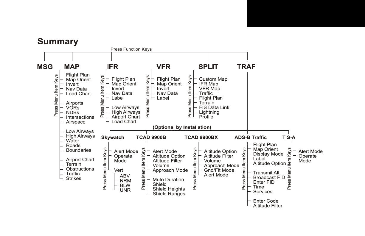
Functions
The MX20 contains thirteen major separate functions for the display of information. The function names are
shown as “smart” keys at the bottom of the display. The “smart” key is the combination of a label above a triangle key at the bottom of the display. The labels above the triangle keys change to reflect the choices available
to you for each function. Press the FN key to show the available functions. Press the “smart” key below the
function label to go to the desired function. While in each function, press the MENU/ENTER key to show the
options for each function. The options are shown on the right side of the display. Press the MENU ITEM key
to manipulate the options. Some options toggle on/off, while some are tri-state (three choices).
Getting Started
Functions
MX20 Functions
• MSG - Message Log
• MAP - Custom Map
• IFR - IFR Chart
• VFR - VFR Chart
• Split - Split Screen
• Traffic - Skywatch/TCAD/IHAS (TAS)
• Traffic - ADS-B TRAF
• Traffic - TIS-A
• FPL - Flight Plan
• TER - Internal/TAWS Terrain
• FIS-B - Flight Information Service
(GDL 90 UAT)
• FIS - Flight Information Service
(WSI InFlight)
• FIS - Flight Information Service
(GDL 69/69A)
• XM - XM Satellite Radio
• LT - Lightning Strikes
• CHART - Chart View
• RADAR - Weather Radar
• SYS - System Information
1

Getting Started
Functions
The Message Log displays information from the MX20 or reported to the MX20 by its external sensors. A
flashing MSG annunciator notifies you of a new message that should be viewed.
The Custom Map function allows you to completely customize the displayed map by overlaying selected
information. The Custom Map can become “cluttered” if you choose every option, so use discretion.
The IFR Chart function provides an IFR en route style map on the display.
The VFR Chart function provides a VFR sectional style map for the display.
The Split Screen function allows up to two of the other functions to be displayed side by side and an optional
vertical profile across the bottom of the display.
The Traffic function (when installed) shows nearby traffic and details about each target.
The Flight Plan function provides details about your flight plan and each waypoint.
The Terrain function shows a color coded map of terrain elevation in relation to your altitude.
The Flight Information Services (FIS) function, when installed, is capable of displaying text and graphic
weather information with GDL 90 and GDL 69/69A installations.
The Lightning (LT) function, when connected to the Goodrich WX500 Stormscope, controls the overlay of
lightning strike information on the map displays.
The Chart View feature provides the capability to view Jeppesen Sanderson Inc. electronic charts. Two basic
types of charts can be viewed: Approach charts and airport surface charts.
The XM function allows the reception of XM Satellite Radio entertainment broadcasts when the GDL 69A is
installed and a subscription to the XM Radio service is activated.
The Radar Function allows weather radar from the ART2000, ART2100, or RS-181A to be displayed.
The System Information function lets you set general preferences, show software version information, and test
the display.
2

Controls
Power/Brightness
Two variations of the Power/Brightness control exist, a rotary knob or a rocker switch. Both are described here.
The power switch is located in the upper right corner of the MX20. Turn the power rotary knob clockwise past
the detent to turn the power on. Turn the power knob fully counterclockwise to turn the power off. With the
power knob pushed in, the brightness is set automatically according to ambient light by a photo sensor. Pull
the knob out and turn the knob to adjust the display brightness manually.
The power switch is located in the upper right corner of the MX20. Press the “+” rocker switch to turn the
power on. Press both the “-” and “+” rocker switches and hold them down to turn the power off. Press the “-”
and “+” rocker switches individually to adjust the display brightness manually. Press the “-” and “+” rocker
switches at the same time until the keys flash, then release to set the brightness automatically.
Function (FN)
The Function keys are made up of one dedicated key on the lower left side of the display and the four “smart”
keys to the right of it. Press the function (FN) key repeatedly to scroll through the available functions. The
functions will appear above the “smart” function keys in turquoise.
Use the FN key to display a list of the main functions, such as Map, IFR, Terrain, etc. Each time you press
the FN key you will step through the list of functions. After you press one of the function “smart” keys at the
bottom of the display, the function keys change to provide options to control the display related to the current
function.
Change the function keys back to the function list by pressing the FN key.
Getting Started
Controls
Power Rotary Switch
Power Rocker Switch
Menu/Enter
The MENU/ENTER key is located on the bottom right corner of the MX20. Press the MENU/ENTER key to
show a menu of options to modify the display of the current function. Press the MENU/ENTER key to hide
the menu. If no action is taken, the menu will automatically extinguish in a few seconds.
3

Getting Started
Data Card
Menu Item Key Layout
Menu Item
The Menu Item keys are on the right side of the MX20. Press the MENU/ENTER key to see the options for the
current function. Press the MENU ITEM key next to each option to scroll through the choices for each option.
Some options support tri-state choices, such as in Map mode. When you select a tri-state option, the option label
will change with each key press between completely filled, partially filled, and empty.
Data Card
The Map database and other information is stored on a data card. The use of a data card allows you to easily
update information.
Only change the data card when the power is turned off.
Handle your data card carefully. Do not touch the connector edge of the data card. To eject the card, use a soft
blunt object to press the data card ejector. Gently pull the card straight out of the slot. Insert a data card by
pushing the card straight into the slot. When fully inserted, the data card and eject button will be flush and
slightly recessed into the bezel.
When contacting your dealer or the Garmin customer service department, eject the data card and write down
the information shown on the label.
Front View of Data Card Slot
4
Data Card Label

Display
MX20
Power/Dimming
Graphic Display
Menu Item
Smart Keys
Menu/Enter Key
Data Card Ejector
Data CardFunction Smart Keys
Function Key
Function Smart
Key Labels
Currently Selected FunctionMounting Screw
Advisory Flags
Message Flag
Zoom
(Map Scale)
TO Waypoint
Identifier
Bearing to
Destination (TO) Wpt
Menu Item Labels
Data Flags
Photosensor
Ownship
Traffic
Traffic Thumbnail
Obstruction
The MX20 display provides text and graphic information to give a “picture” of your flight and surroundings.
The display brightness may be set manually or allowed to automatically adjust to ambient light conditions. At
the bottom of the display, labels above the function keys change to show the different choices for each function
to allow access to commonly used actions. A typical Custom Map function display is shown below.
MX20s with a rotary Power/Dimming knob will go into a pre-heat mode for a short period of time on start-up.
During the pre-heat mode, the display will remain dark. The pre-heat mode is designed to extend the life of
the LCD backlight.
Getting Started
Display
5

Getting Started
Annunciations
Annunciations
Advisory flags, data flags, and messages appear on the display to give information about the status of the MX20
or to provide operating information.
Advisory Flags
Annunciations will appear on the upper left side of the display to provide advisories for Traffic, Terrain, and
Lightning. Advisory information is monitored and displayed regardless of the selected function. Advisory flags
will flash for approximately 10 seconds when they first appear and then turn solid while they are still valid.
Advisory icons will reduce in size if more than two advisory conditions exist.
Advisory Flags
ADS-B Traffic
The Traffic advisory flag will appear on the left side of the display when traffic is reported to be within ±2000
feet of your altitude and 5 nm of your location. This Traffic advisory is only available when the ADS-B system
with a UAT data link is installed and operational. Refer to the TIS Traffic section for a description of TIS-A and
TIS-B.
Skywatch/TCAD/TIS-A Traffic
The Traffic Advisory/Alert will appear in amber on the left side of the display when the traffic sensor indicates
an alerting condition. Refer to the TIS Traffic section for a description of TIS-A and TIS-B.
Terrain
The Terrain advisory flag will appear on the left side of the display when the terrain surface or obstacle altitude
is within approximately 500 feet of your altitude and within approximately two minutes of flight in any direction.
Lightning
The Lightning advisory flag will show on the left side of the display when the WX500 sends an indication that
lightning has been detected within 50 nm of your location. See the WX500 manual for details about range and
other capabilities.
6

Data Flags
Data flags appear on the left side of the display to notify you when there is a loss of reported information.
The data usually displayed, such as lightning or nearby terrain, may still exist, but may not be displayed for
technical reasons. For instance, when the amber TRAF data flag appears it means that the MX20 is not receiving
Traffic information from the sensor. So, traffic may exist in your vicinity, but will not be displayed on the MX20.
All flags are amber unless otherwise indicated.
Data Flag Description
No valid position information is available from the
source. Do not expect a valid position representation
on the maps. The Ownship symbol will have an “X”
through it.
No valid route (flight plan) is available from the external navigation source. Route (flight plan) information
will not be shown on the maps.
No valid altitude information is available from the
external source. Altitude related functions will not
operate, such as terrain awareness.
No traffic information is received from the optional
traffic sensor. Traffic will not be displayed. Your position information may not be broadcast in ADS-B
capable systems.
The GPS receiver in the GDL 90 UAT is not reporting
a valid position. ADS-B broadcast will not include a
position report.
No valid lightning detection information is being
received from the optional Stormscope sensor. Strike
and cell information will not be displayed.
Getting Started
Data Flags
Message Flag
The Message flag will appear on the
lower left side of the display when a new message
is posted. Go to the Message function to view the
information about the operation or status of the
MX20.
ADS-B Status Annunciation
When the MX20 Code Edit option is
enabled, an annunciation will appear
in the top left portion of the display
to indicate the Flight ID broadcast
status and the current transponder
code.
The top half will indicate the operation being
used: Broadcast FID (FID), Broadcast VFR (VFR),
or Stand-By (STBY). The bottom half will show
the transponder code that is being used. When a
transponder code has not been selected, the code
in the bottom half will be replaced by dashes.
7

Getting Started
Data Flags
Data Flag Description
Terrain coverage is not available for some part of the
terrain advisory coverage area. Terrain advisories may
not be provided.
When connected to the SL30, indicates the SL30 is not available or valid. ILS, OBS, and VORs will not be highlighted.
No valid traffic information is being received from the
optional Ryan TCAD sensor. Traffic information will
not be displayed.
Indicates that radar status information is not available
from the optional external radar transmitter head.
Radar related functionality may not be available.
(Green)
(Green Flashing)
(Green)
Indicates that the radar is ON and transmitting RF
energy. Appropriate precautions should be taken.
Indicates that the radar is in Hold and is transmitting
RF energy. Appropriate precautions should be taken.
Displayed when the GDL 90 is in Ident mode.
No valid datalink information is available from the
optional external source.
No valid terrain information is available from the
optional external source.
No valid datalink information is available from the
optional external source.
No valid TIS-A information is available from the
optional external source.
8

Basic Operation
Use the following items to get a basic feel for the operation of the MX20. The basic steps for using any of the
separate functions of the MX20 are:
• Turn the power on.
• Adjust the brightness or set it to automatic.
• Check that all tests pass on the Start Up screen.
• Press the FN key to view available functions. Each press of the FN key will step through the lists of
functions.
• Press the key below the function label to select the desired function.
• Confirm or enter the current barometric pressure
• Press the MENU/ENTER key to display available options.
• Press the MENU ITEM key next to the displayed option to choose desired capabilities. Some options
use multiple key presses for different states for the option. Press the MENU/ENTER key again to
extinguish the option display.
• Refer to the Detailed Operation section for more details on each function.
Brightness
Rotary Knob Model
With the Power knob pulled out, turn the knob in each direction to adjust the display brightness manually.
Manual brightness mode may be selected to adjust the display for difficult lighting conditions. Push the knob
in, and the brightness is adjusted automatically according to the ambient light. When the brightness is set
automatically, the display will not dim below a pre-defined level.
Getting Started
Basic Operation
Power On
Turn the power rotary knob clockwise past the
detent to turn the power on OR press the “+”
rocker switch to turn the power on. The MX20
will progress through a series of startup screens.
The final startup screen shows System Information and the results of the Self-Test.
Pre-Heat Mode
MX20s with the rotary power/dimmer knob will
go into a pre-heat mode for a short period of
time on start-up. During the pre-heat mode, the
display will remain dark. The pre-heat mode is
designed to extend the life of the LCD backlight.
Rocker Switch Model
Press the “-” and “+” rocker switches at the same time briefly to set the brightness automatically according to
ambient light by the photo sensor. Press the “-” and “+” rocker switches alone to adjust the display brightness
manually. When the brightness is set automatically, the display will not dim below a pre-defined level.
9

Getting Started
Start Up and Baro Correction
Start Up Screen After Passing Tests
Start Up Screen
The Start Up screen is displayed while the MX20 goes through its initialization and testing routines. System
information is shown that provides the MX20 software and database versions. The results of the self test are
shown. A check mark shows that the test passed. If any of the Self-Tests fail (red “x”), contact your dealer or
the factory.
Confirm Current Baro Correction
A window may appear at startup, and then every 30 minutes, that displays the current barometric value. You
must verify the current value or enter a new value. Press BARO + to increase the value. Press BARO - to
decrease the value. Press OK to confirm the existing values or to accept changes you have just entered.
Barometric Pressure Confirmation
10

Function Selection
Press the FN key to view the different Functions. The functions are shown above the function “smart” keys on
the lower part of the display in blue. Press the function key under the function label to activate that function.
The labels above the function key will change to reflect the custom “smart” controls for that function. All of the
described functions may not be available in each installation.
Function Description
MSG Message Log Function
MAP Custom Map Function
IFR IFR En Route Map
VFR VFR Sectional Map
SPLIT Split Screen (Displays Two Functions)
TRAF Traffic Display
FPL Flight Plan Information
TER Terrain Depiction
FIS Flight Information Service - Graphic and Text Weather
XM XM Satellite Radio Audio
LT Lightning Detection and Reporting
CHART Chart View
RADAR Weather Radar Function
SYS System Information
Getting Started
Function Selection
11

Getting Started
Advisory Hot Key
Advisory Hot Key
The “Advisory Hot Key” feature allows advisory conditions to be quickly viewed with minimal effort by the
pilot. This feature is comprised of three components:
1) An advisory condition is indicated by a white advisory flag on the left side of the screen and the
corresponding Function label will also be highlighted in white when selecting a new Function with
the FN key. This feature allows any Function with a pending advisory to be quickly recognized in the
Function menu.
2) When a function is entered that has an advisory posted, the zoom level will be adjusted to show the
advisory causing object (terrain for example), and the map orientation will be forced to “Track Up 360”
to get a good view of what is around the aircraft.
3) When returning to the previous Function after viewing a Function with an advisory, the original zoom
and map mode will be restored.
This feature is designed to allow the pilot to establish a preferred “cruise” map setup and quickly view an
advisory, then return back to the previous setting. For example:
Normal Cruise Condition
Custom Map Function is being viewed at 5 nm in the ARC mode.
Terrain Advisory occurs at 10 nm in front of aircraft: The Terrain Advisory Indicator flashes then goes steady
on the left side of the display.
Viewing the Advisory
The pilot presses the FN key and sees the TER Function highlighted in white, indicating it has an advisory
condition. Pressing the TER key to enter the Terrain Function at this point will automatically adjust the zoom
level to 10 nm and place the unit in full “360” mode to show overall situational awareness.
Returning To Normal Condition
After evaluating the advisory, to return to normal viewing simply select the original Function that was being
viewed before the advisory was viewed. When this is done, the zoom level will be set back to 5 nm and the
display mode will be returned to ARC mode.
12

Alert Hot Key
Traffic alerts go one step further than the Advisory hot key feature and will automatically bring up the Function Menu showing the Traffic function. This is called the “prompt” mode. A single key press can then be used
to switch the display to the Traffic function. The Alert hot key feature will automatically clear when the traffic
alert condition no longer exists.
Also note that a “pop-up” mode can be enabled on the Traffic function, which makes the Traffic page “pop-up”
when a Traffic Advisory occurs. The “prompt” or “pop-up” mode is selected in the Traffic function.
Options Menu
Most functions have a number of options available. Press the MENU/ENTER key to see the options for the
current function. You change an option by pressing one of the Menu Item keys that are to the right of the displayed option. Many options have more than two choices. Press the same MENU ITEM key repeatedly to view
or select the available choices. Some functions have several pages of options. The lower MENU ITEM key will
allow you to reach the Next Page when multiple pages are available. Press the MENU/ENTER key a second
time to remove the menu from view or wait a few seconds for the options to automatically extinguish.
Thumbnail Feature
The Thumbnail feature provides a small map depiction that is overlaid in the upper left corner of the MX20
display. It provides for enhanced traffic and terrain situational awareness when not specifically viewing traffic
or terrain related functions. For example, both traffic and terrain situational awareness can be maintained
while viewing the Flight Plan Function.
The Thumbnail is shown in both a small and large format, depending on the function currently being viewed.
The Thumbnail is typically presented in the larger format when overlaid on a map. However, on some functions where the Thumbnail would overlay critical information, the smaller format is utilized.
The Thumbnail provides a fixed 5 nm range view of conflicting traffic and terrain. The range depicted by the
Thumbnail is not affected by the current zoom scale set on the main map functions.
Getting Started
Alert Hot Key, Options, Thumbnail
13

Getting Started
Thumbnail and TIS
Thumbnail view of conflicting terrain and traffic
14
Traffic on Thumbnail
TIS, TAS, TCAS, or ADS-B traffic is shown on the Thumbnail in the same symbology used within the Traffic Function. Any traffic within sensor range and 5 nm is shown, in addition to traffic causing an amber Traffic Alert (TA)
traffic. Note that the MX20 supports one traffic sensor in any installation.
Terrain on the Thumbnail
Only “Red” terrain within the 5 nm range is presented on the Thumbnail. This correlates directly to terrain that
is rendered in red on the normal Terrain Function based on the internal terrain database. External TAWS-based
terrain from the Goodrich Landmark is not shown on the Thumbnail.
Obstructions on the Thumbnail
Only “Red” obstructions within the 5 nm range are presented on the Thumbnail. This correlates directly to
obstructions that are rendered in red on the other functions.
Thumbnail Activation
The Thumbnail incorporates logic that will either show or hide the thumbnail from view. It will only be shown
when there is data to be presented and will be removed if not. For example, if there is no “Red” terrain or traffic
within 5 nm, the Thumbnail will be hidden from view. The Thumbnail will not appear on the Traffic Function page if only traffic is presented in the Thumbnail. Correspondingly, it is not shown on the Terrain page if
only terrain is presented in the Thumbnail. This logic eliminates redundant views that would be created by the
Thumbnail and normal views of traffic and terrain. Additionally, the Thumbnail is disabled while operating on
the ground. This state is determined by the “En Route/Ground Transition Speed” set in the System Function
page and is based on GPS ground speed.
Traffic Information Services (TIS)
There are two versions of TIS: TIS-A and TIS-B. Both are described below.
In the TIS-A system, ground radar sensors collect target information. The ground radar sensor then determines
the targets in the vicinity of your aircraft and their bearing relative to your track. Up to eight of the targets are
transmitted by the ground radar sensor the next time it communicates with your TIS-A enabled transponder.
In the TIS-B system, the ground radar sensors collect target information much the same as in the TIS-A system.
However, with TIS-B, all targets collected by the ground radar sensor are broadcast to all aircraft equipped with
UAT data link radios and that are within coverage of UAT ground broadcast stations.
Getting Started
Function Summary
15

Getting Started
Function Summary
16

Getting Started
Function Summary
17

Detailed Operation
Message Log
Message Log Function Display
Message Log (MSG)
The Message function displays information about the status of the MX20. Messages may be logged by either
the MX20 internal system or by one of the external sensors. The amber MSG flag will flash until the message is
viewed. The MSG flag will remain in view while any messages remain in the message log. New messages that
have not been viewed will be highlighted as bold text.
1. Press FN until you see the MSG function key.
2. Press the MSG key.
3. Use the UP/DOWN arrow “smart” keys to move to additional messages, if more than one page of
messages exist.
4. Press CLEAR to remove the stored messages.
18
 Loading...