

Page 1
Reactor™ 40 Kicker Mercury EFI
Installation Examples
You can use these photographic examples to help when following the
instructions included with your Reactor 40 Kicker and Mercury EFI motor.
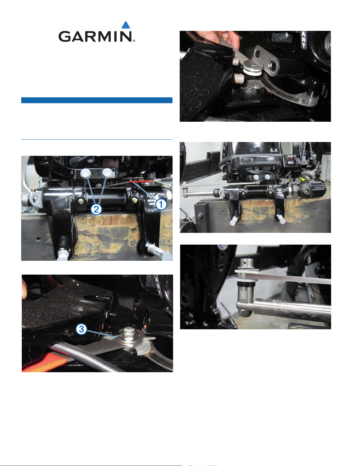
Removing the Tiller Lock
You must use caution when disassembling the motor to remove the tiller
lock and installing the steering and throttle actuators. The provided photos
are examples, and may not accurately represent your motor. For further
information, you may need to consult your motor manufacturer for guidance.
Garmin is not responsible for damage caused to your motor when removing
the tiller lock or installing this product.
NOTE: If your motor has a tiller lock
the steering actuator. Remove the bolts
NOTICE:
➊➊, it must be removed before installing
➋➋ to access the tiller lock assembly.
Steering Actuator Installation Examples
Installing the Steering Actuator Bracket Between the Tiller Arm and Motor
Tiller Lock
Removing the Tiller Lock
Remove the tiller lock assembly ➌➌ before installing the linkage arm assembly.
Complete Steering Actuator Installation
Steering Actuator Spacer Stack Order
April 2020 190-02451-25_0A Printed in Taiwan
© 2020 Garmin Ltd. or its subsidiaries
Page 2
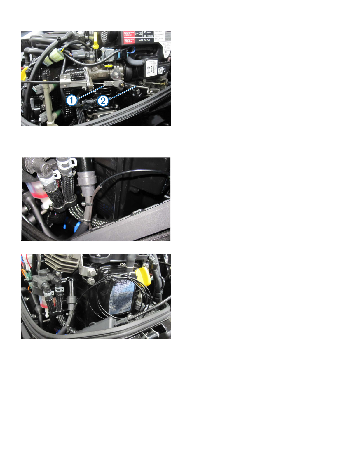
Throttle Actuator Installation Examples
RPM Cable Installed on Spark Plug Cable Exterior
Complete Throttle Installation
NOTE: The existing linkage must be replaced with linkage from bag A ➊➊. The
existing tiller throttle linkage rod must be replaced with the new linkage rod
in parts bag 4.
➋ ➋
Complete RPM Cable Installation
RPM Cable
NOTE: The RPM cable cannot be shortened. Excess RPM cable must be
secured inside the cowling in a location that does not interfere with moving
parts.
April 2020 190-02451-25_0A Printed in Taiwan
© 2020 Garmin Ltd. or its subsidiaries
 Loading...