

Garmin GPS 40 Owner's Manual & Reference
Owner’s
Manual
&
Reference
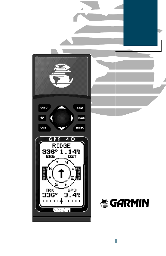
GPS 40
Personal
Navigator
TM
®

Software Version 3.0 or above
© 1996 GARMINCorporation
1200 E. 151st Street, Olathe, KS USA 66062
GARMIN (Europe) LTD
Unit 5, The Quadrangle, Abbey Park Industrial Estate, Romsey, UK SO51 9AQ
All rights reserved. No part of this manual may be reproduced or transmitted in any
form or by any means, electronic or manual, including photocopying and recording, for
any purpose without the express written permission of GARMIN.
Information in this document is subject to change without notice. GARMIN reserves
the right to change or improve its products and to make changes in the content without
obligation to notify any person or organization of such changes or improvements.
GARMIN™, GPS 40 ™, Personal Navigator™, AutoLocate™, TracBack™ and
MultiTrac8™ are all trademarks of GARMIN Corporation, and may not be used without
the expressed permission of GARMIN.
May 1996 Part #190-00124-00 Rev. A Printed in Taiwan.

Introduction
GPS 40 XL
Preface
TM
Personal Navigator
OWNER’S MANUAL
Welcome to the smallest, easiest-to-use GPS navigator for recreational use!
The GPS 40 represents GARMIN’s continuing commitment to provide outdoors sports enthusiasts with quality navigation information in a versatile,
accurate and user-friendly design you’ll enjoy for years to come. To get the
most of your new GPS unit, it is important that you take the time to read
through this owner’s manual to understand the operating features of the GPS
40. The manual is organized into three sections for your convenience:
Section One takes you through step-by-step instructions to initialize the
receiver for first-time use.
Section Two introduces you to the basic features of the unit and provides
a quick-start orientation to the GPS 40. This section has been designed to
acquaint you with the unit and provide a basic working knowledge necessary
to use the unit in typical conditions.
Section Three provides a detailed reference to the advanced features and
operations of the GPS 40 in a topical format. This allows you to concentrate
on a specific topic quickly, without reading through entire sections of text that
you may not need.
Packing List
Before getting started with your GPS receiver, check to see that your
GARMIN GPS 40 package includes the following items. If you are missing any
parts, please contact your dealer immediately.
Standard Package:
• GPS 40 Receiver • Carrying Case and Wrist Strap
• Owner’s Manual • Quick Reference Card
• Instructional Video • 4 AA Batteries
Thanks for choosing the GARMINGPS 40. We hope it will help you get
the most out of your outdoor recreation adventures.
i

Introduction
Cautions
CAUTION
The GPS system is operated by the government of the United States,
which is solely responsible for its accuracy and maintenance. The system is
subject to changes which could affect the accuracy and performance of all
GPS equipment. Although the GPS 40 is a precision electronic NAVigation
AID (NAVAID), any NAVAID can be misused or misinterpreted and therefore,
become unsafe.
Use the GPS 40 at your own risk. To reduce the risk of unsafe operation,
carefully review and understand all aspects of this Owner’s Manual and thoroughly practice operation using the simulator mode prior to actual use. When
in actual use, carefully compare indications from the GPS 40 to all available
navigation sources including the information from other NAVAIDs, visual
sightings, charts, etc. For safety, always resolve any discrepancies before continuing navigation.
NOTE:This device complies with Part 15 of the FCC limits for Class B
digital devices. This equipment generates, uses, and can radiate radio frequency energy, and if not installed and used in accordance with the instructions,
may cause harmful interference to radio communications. However, there is
no guarantee that interference will not occur in a particular installation. If this
equipment does cause harmful interference to other equipment, which can be
determined by turning the equipment off and on, the user is encouraged to
try and correct the interference by relocating the equipment or connecting the
equipment to a different circuit than the affected equipment. Consult an
authorized dealer or other qualified service technician for additional help if
these remedies do not correct the problem. Operation is subject to the following conditions: (1) This device cannot cause harmful interference, and (2) this
device must accept any interference received, including interference that may
cause undesired operation. The GPS 40 does not contain any user-serviceable
parts. Repairs should only be made by an authorized GARMIN service center.
Unauthorized repairs or modifications could void your warranty and your
authority to operate this device under Part 15 regulations.
ii

Introduction
Table of
Contents
SECTION ONE Introduction
GPS Definitions/Navigation Basics . . . . . . . . . . . . . . . . . . . . . . . . . . .2-4
Initializing the Receive/Remote Antenna and Wrist Strap Usage . . . . .5-8
SECTION TWO Getting Started
Power On/Satellite Status Page . . . . . . . . . . . . . . . . . . . . . . . . . . . . . . .9
Sky View/Position Page . . . . . . . . . . . . . . . . . . . . . . . . . . . . . . . . . . .10
Marking a Position . . . . . . . . . . . . . . . . . . . . . . . . . . . . . . . . . . . . . .11
Position and Moving Map Basics . . . . . . . . . . . . . . . . . . . . . . . . . . . .12
GOTO and Steering Guidance . . . . . . . . . . . . . . . . . . . . . . . . . . .13-14
Page Sequence and Menu Page . . . . . . . . . . . . . . . . . . . . . . . . . . . . . .15
Clearing the Track Log/Power Off . . . . . . . . . . . . . . . . . . . . . . . . . . . .16
SECTION THREE Reference
Satellite Status Page . . . . . . . . . . . . . . . . . . . . . . . . . . . . . . . . . . .17-19
Position Page . . . . . . . . . . . . . . . . . . . . . . . . . . . . . . . . . . . . . . . . . . .20
Creating and Using Waypoints . . . . . . . . . . . . . . . . . . . . . . . . . . .21-27
GOTO and MOB Mode . . . . . . . . . . . . . . . . . . . . . . . . . . . . . . . . . . .28
TracBack Navigation . . . . . . . . . . . . . . . . . . . . . . . . . . . . . . . . . . .29-30
Creating and Using Routes . . . . . . . . . . . . . . . . . . . . . . . . . . . . . .31-36
Compass and Highway Page Steering Guidance . . . . . . . . . . . . . . .37-39
Moving Map Plotting . . . . . . . . . . . . . . . . . . . . . . . . . . . . . . . . . .40-43
Menu Page and Auxiliary Functions . . . . . . . . . . . . . . . . . . . . . . .44-52
Simulator Mode . . . . . . . . . . . . . . . . . . . . . . . . . . . . . . . . . . . . . . . .53
Appendix A—Messages/Time Offsets . . . . . . . . . . . . . . . . . . . . . . .54-55
Appendix B—Map Datums . . . . . . . . . . . . . . . . . . . . . . . . . . . . . .56-57
Appendix C—Specifications, Wiring, and Battery Replacement . . .58-59
Appendix D—Accessories . . . . . . . . . . . . . . . . . . . . . . . . . . . . . . . . .60
Appendix E—Index . . . . . . . . . . . . . . . . . . . . . . . . . . . . . . . . . . .61-62
1

Introduction
GPS
Definitions
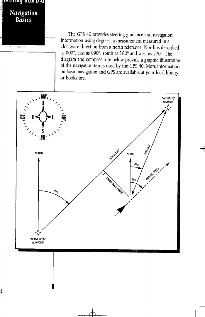
The GPS 40 is a powerful navigation tool that can guide you anywhere in
the world. To better understand its operation and capabilities, it may be helpful to review the basic terms and concepts briefly explained below.
Other navigation and GPS definitions used in the manual are defined in the
appropriate reference sections of the manual.
Almanac Data
Satellite constellation information (including location and health of satellites) that is transmitted to your receiver from every GPS satellite. Almanac data
must be acquired before GPS navigation can begin.
Bearing
The compass direction from your position to a destination.
Course Made Good (CMG)
The bearing from the ‘active from’ position (your starting point) to your present position.
Crosstrack Error (XTE)
The distance you are off a desired course in either direction.
Desired Track (DTK)
The compass course between the ‘from’ and ‘to’ waypoints.
Differential GPS (DGPS)
An extension of the GPS system that uses land-based radio beacons to transmit position corrections to GPS receivers.
Estimated Time of Arrival (ETA)
The time of day of your arrival at a destination.
Estimated Time Enroute (ETE)
The time left to your destination at your present speed.
2

Introduction
GPS
Definitions
Grid
A coordinate system that projects the earth on a flat surface, using
square zones for position measurements. UTM/UPS and Maidenhead
formats are grid systems.
Ground Speed
The velocity you are traveling relative to a ground position.
Latitude
A north/south measurement of position perpendicular to the earth’s
polar axis.
Longitude
An east/west measurement of position in relation to the Prime
Meridian, an imaginary circle that passes through the north and south
poles.
Navigation
The process of travelling from one place to another and knowing
where you are in relation to your desired course.
Position
An exact, unique location based on a geographic coordinate system.
Track (TRK)
The direction of movement relative to a ground position.
Universal Transverse Mercator(UTM)
A grid coordinate system that projects global sections onto a flat sur-
face to measure position in specific zones.
Velocity Made Good (VMG)
The speed you are traveling in the direction of the destination.
Waypoint
A specific location saved in the receiver’s memory.
3
Getting Started
Getting Started with your GPS
Welcome to the exciting world of GARMINGPS! The
GPS 40 represents GARMIN’s continuing commitment to
provide outdoor enthusiasts with quality navigation information in a versatile, user-friendly design they will enjoy
for years to come. To get the most out of your GPS 40, be
sure to read through the initialization and Getting-Started
sections of this manual, and refer to the reference section
for complete details on the GPS 40’s advanced features.
Initializing Your GPS for First-Time Use
The GPS 40 calculates your position and movement by
tracking signals sent from GPS satellites. Each of the 24
GPS satellites circle the earth twice a day in a very precise
orbit, and transmit information back to earth. In order to
determine a position fix, your GPS receiver needs to continuously “see” at least three satellites.
Because a GPS receiver can only see satellites above the
horizon, it needs to know what satellites to look for at any
given time. By using an almanac (a timetable of satellite
numbers and their orbits) stored in the receiver’s memory,
the GPS 40 can determine the distance and position of any
GPS satellite.
To use this almanac data, your GPS receiver needs to
know where you are, or be given the opportunity to “find
itself”. Once you initialize the unit to this position, the GPS
40 will usually compute a fix within a few minutes.
Remember, this process is only necessary under the
following conditions:
• First-time use from the factory.
• The receiver has been moved over 500 miles from
the last calculated position with power off.
• The receiver’s memory has been cleared and all
stored data has been lost.
Initialization
&
Wrist Strap
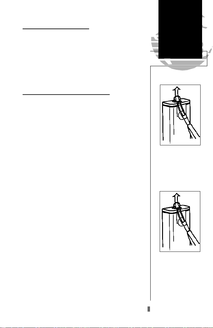
Wrist Strap
To attach the GPS 40’s wrist
strap, thread the strap
through the D-ring on the
battery compartment cover.
Take the solid end of the
strap and thread it through
the slot at the other end of
the strap and tighten.
5
Getting Started
Acquiring
Satellites&
Remote
Antenna
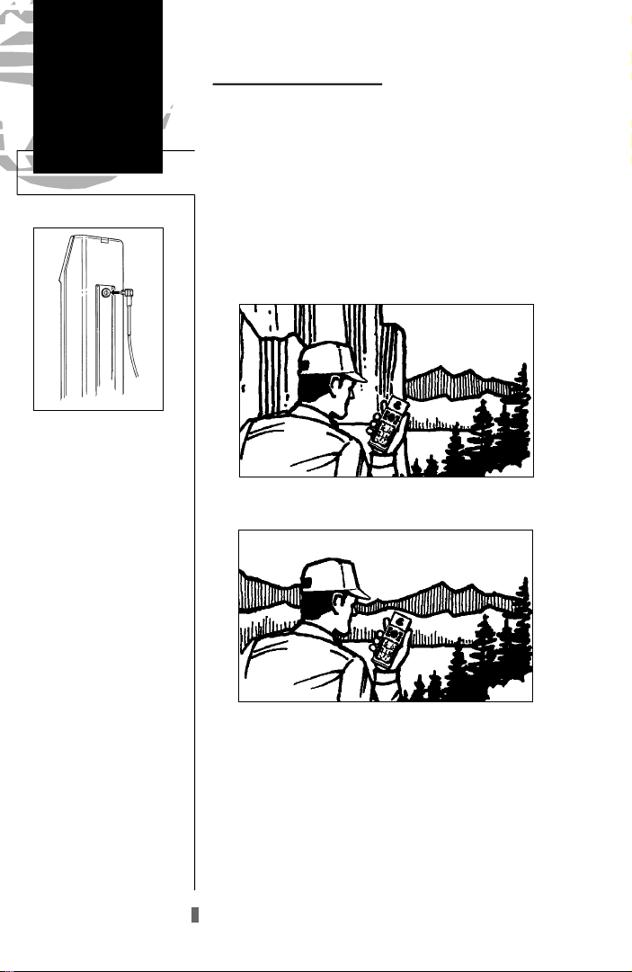
Remote Antenna
An optional remote
antenna may be used with
the GPS 40. The remote
antenna will improve the
receiving capabilities of the
unit by magnifying weaker
signals which the built-in
antenna may not be able to
use.
The remote antenna is
attached by plugging it into
the outlet on the back of the
receiver (see above).
To order an antenna use
the order form in Appendix
B or contact your local
GARMIN dealer for more
information.
Acquiring Satellite Signals
Because the GPS 40 relies on satellite signals to provide
you with navigation guidance, the receiver needs to have an
unobstructed, clear view of the sky for best performance.
What exactly does this mean? In a nutshell, the GPS receiver’s view of the sky will generally determine how fast you
get a position fix, or if you get a fix at all. GPS signals are
relatively weak and do not travel through rocks, buildings,
people, mountains and other significant structures, so you
need to make sure that you’re not standing next to a tall
building or a wall of cliffs when acquiring satellites.
Obstructed View of the Sky
Clear View of the Sky
Once the GPS has calculated a position fix, you’ll usually have anywhere from four to eight satellites in view. The
GPS 40 will now continuously select the best satellites in
view to update your position. If some of the satellites in
view get blocked or “shaded” the receiver can simply use an
alternate satellite to maintain the position fix. Although a
GPS receiver needs four satellites to provide a 3D fix, the
GPS 40 can maintain a 2D fix with only three satellites.
6
Before You Initialize
Take the GPS 40 outside and find a large, open area (try
a nearby park) that has a clear view of the sky from horizon
to horizon. Hold the receiver at a comfortable height, at
arm’s length from your body, with the unit parallel to the
ground.
Do your best to stay away from buildings or other
!
structures that could block the path of signals to the
#
receiver. GPS signals do not travel through rocks,
mountains, buildings, metal surfaces or other significant structures.
To turn the GPS 40 on:
1. Hold the unit so the built-in antenna (the flat area above
the display) is parallel to the ground.
2. Press and hold Buntil the receiver turns on.
The welcome page will be displayed while the unit conducts a self test. Once testing is complete, the welcome
page will be replaced by the status page, with the EZinit
prompt ready for you to select one of two initialization
methods:
• Select Country— allows you to initialize the receiver
by selecting your present position from a list of countries in the GPS 40’s internal database. This usually
provides a position fix in 3-5 minutes.
• AutoLocateTM— allows the GPS 40 to initialize itself
and calculate a position fix without knowing your
present position. This usually provides a position fix
in 7.5-15 minutes.
If the EZinit prompt has not automatically appeared
on the status page:
1. Press the Ekey.
If you’ve already initialized the GPS 40 and the EZinit
prompt appears, highlight the ‘no re-init’ selection with the
arrow keypad and press E. The EZinit prompt may
appear if you’ve had the unit on in normal mode while
indoors, or if the antenna is shaded while acquiring satellites in normal or battery saver mode.
Getting Started
Powering Up
Hold the receiver so the
built-in antenna is parallel
to the ground.
Welcome Page
7
Getting Started
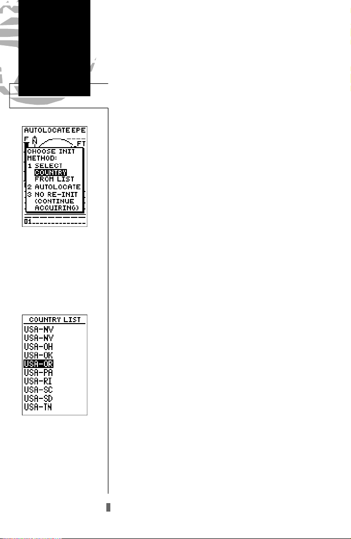
EZinit
The EZinit prompt will
automatically appear if the
receiver needs to be initialized. The prompt may also
appear during normal use if
the antenna is shaded or the
unit is indoors.
Use the arrow keypad to
highlight the country and
region or state (if necessary)
of your present po sition
f rom the l ist and pre s s
ENTER. If the country is
not listed, select the closest
country instead.
To initialize the receiver:
1. If the ‘country’ option is not highlighted, press theDkey
repeatedly to move the field highlight to the ‘country’
option.
2. Press the Ekey.
3. Use theDkey to scroll through the list options until the
country of your present position appears.
4. Use theU key to highlight the country/state/region
you’re in. If the country you’re in is not listed, select another country within 500 miles of your present position.
5. Press Eto finish.
The GPS 40 will now begin searching for the appropriate satellites for your position and should acquire a fix
within 3-5 minutes. You can verify that you have acquired a
fix by watching the status page transition to the position
page (provided you haven’t pressed any other buttons) or
looking for a 2D or 3D NAV status at the top left corner of
the status page. To prevent accidental battery power loss,
the GPS 40 will automatically shut off 10 minutes after the
last keystroke if the unit is not tracking at least one satellite
and has never acquired a position fix.
If you have trouble initializing the receiver or getting a
position fix, check the following:
• Does the receiver have a clear view of the sky?
If there are large buildings, rocks, or mountains or if
there is heavy tree cover, the receiver may not be receiv-
ing enough satellite signals to calculate a fix.
• Have you selected the right country/state/region
from the EZinit list?
Check for the correct approximate lat/lon on the position page or reselect the appropriate country from the
list to restart the initialization.
• Have you moved more than 500 miles from the last
calculated position with the receiver off?
Reinitialize the receiver, selecting the
country/state/region of your new location from the
EZinit list.
8

Getting Started
Getting-Started Tour
Now that your GPS 40 has been initialized, it’s time to
take a tour through the it’s basic features and functions. The
tour assumes that you have initialized the receiver and have
not changed any of the factory settings (units of measure,
selectable fields, etc). If you have changed any of the
default settings, the pictures and descriptions may not
match your unit’s configuration.
Powering Up and Taking a Fix
Take the GPS 40 outside and find an open area where
the receiver will have a clear view of the sky. Hold the
receiver at a comfortable height, at arm’s length from your
body, with the internal antenna parallel to the ground.
To turn the unit on:
1. Press and hold Buntil the receiver turns on.
A welcome page will be displayed while the unit conducts a self test. Once testing is complete, the welcome
page will be replaced by the satellite status page and the
GPS 40 will begin acquiring satellites.
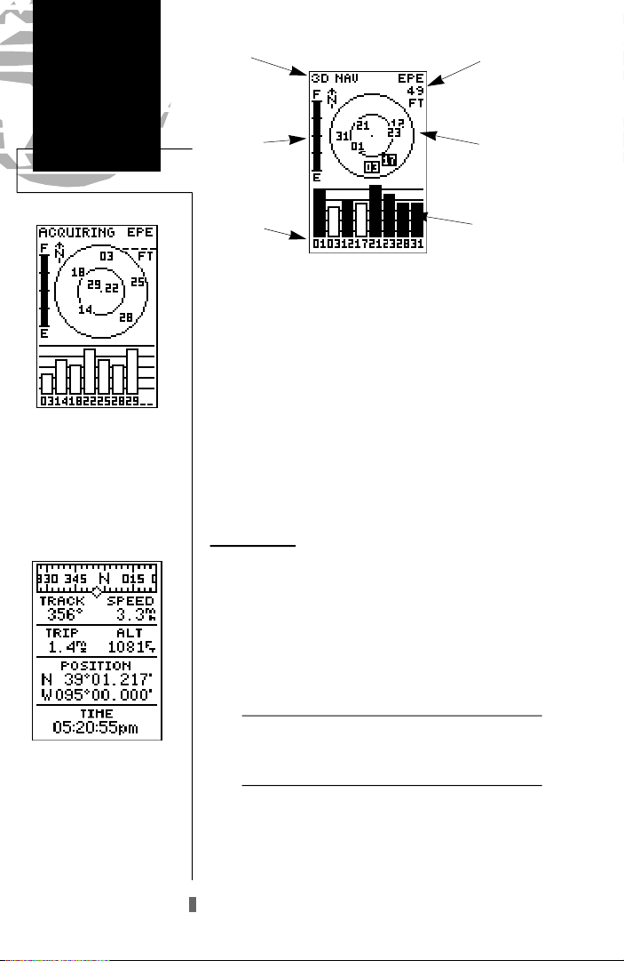
Satellite Status Page
The GPS 40’s satellite status page provides a visual reference of satellite acquisition and position. As the receiver
locks onto satellites, a signal strength bar will appear for
each satellite in view, with the appropriate satellite number
(1-32) underneath each bar. The progress of satellite acquisition is shown in three stages:
• No signal strength bars— the GPS 40 is looking
for the satellites indicated.
• Hollow signal strength bars— the GPS 40 has
found the satellite(s) and is collecting data.
• Solid signal strength bars— the GPS 40 has col-
lected the necessary data and the satellite(s) is
ready for use.
Note that each satellite has a 30-second data transmission that must be collected (hollow bar status) before the
satellite may be used for navigation (solid bar status). Once
a fix has been calculated, the GPS 40 can take on the easier
task of updating your position, track and speed by selecting
and using the best satellites in view.
Power On/
Satellite Status
Welcome Page
Status Page
The signal strength bars at
the bottom of the page will
not appear until the GPS 40
has f ound the satellites
indicated at the bottom of
the screen.
9
Getting Started
Sky View/
Position Page
Status
Horizontal
Accuracy
Once satellites have been
found, hollow signal strength
bars will be displayed while
data is being collected. The
hollow bars can be used to
help determine if satellites
are being shaded.
Battery
Indicator
Satellite
Number
Satellite
Sky View
Signal Strength
Indicators
The satellite sky view shows a bird’s-eye view of the
position of each satellite relative to the unit’s last known
position. The outer circle represents the horizon (north up);
the inner circle 45º above the horizon; and the center point
directly overhead. You can use the sky view to help determine if any satellites are being blocked, and whether you
have a current position fix (indicated by a ‘2D NAV’ or ‘3D
NAV’ in the status field.
Once sufficient signals have been acquired, the status
page will be replaced with the position page, provided you
have not pressed any other buttons.
Position Page
The second page in the GPS 40’s main page sequence is
the position page. The position page shows where you are,
what direction you’re heading and how fast you’re going,
and is particularly helpful when you do not have an active
destination selected. The graphic display at the top of the
page indicates your cardinal heading (while you’re moving)
with the track and speed indicated below.
Position Page
In addition to dis playing
your position coord i n a t e s ,
the position page shows
your track and speed over
the ground. Speed and altitude data may fluctuate due
to Selective Availability.
10
The graphic compass display is designed to show
!
#
your current track and does not serve as a true
magnetic compass while you’re standing still.
The rest of the page shows your current position in
three dimensions: latitude, longitude and altitude. The
GPS 40 uses this basic information to mark exact positions
as waypoints, which help guide you from one place to
another. A trip odometer and 12/24 hour clock are also
provided.
Getting Started
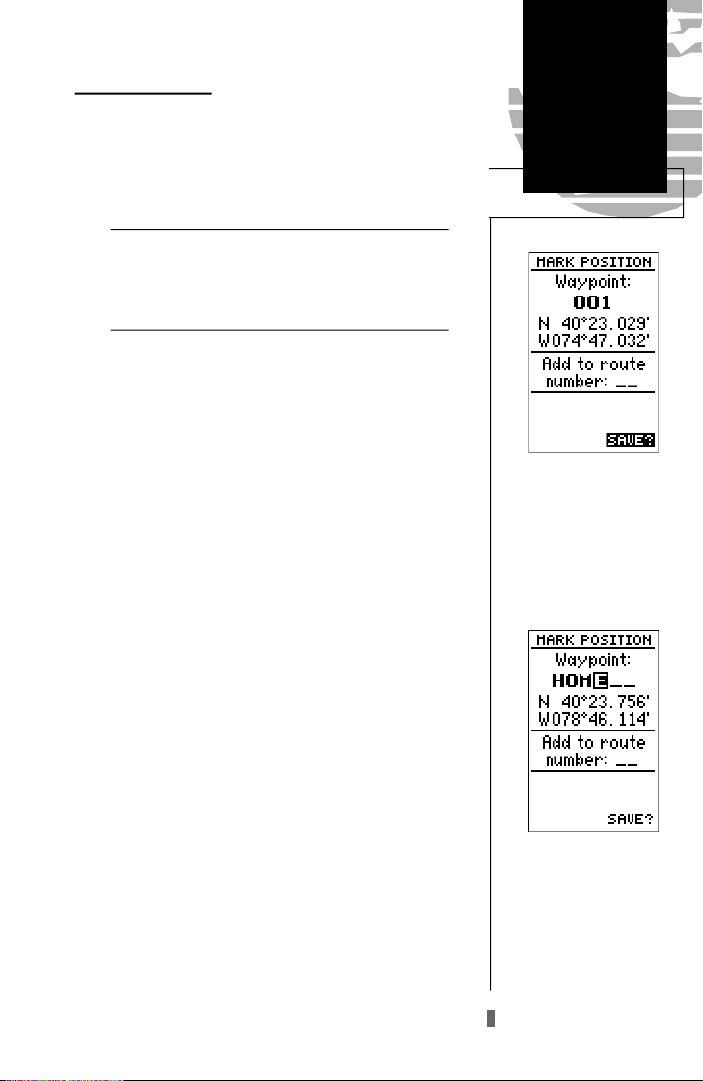
Marking a Position
Now that you’ve acquired a position, let’s mark it as a
waypoint for future reference.
1. Press the Mkey to capture and hold your position.
To mark a position, you must have obtained a 2D or
!
#
3D fix, or have the receiver in simulator mode. If
you try to mark a position without a position fix, you
will be alerted with a ‘No GPS Position’ message.
The mark position page will appear, showing the captured position and a default 3-digit waypoint name. Let’s
change the default name to something a little more meaningful, like ‘HOME’.
1. Press theUkey twice to move the field highlight from
the ‘save’ field to the name field.
2. Press Eand Lto clear the default waypoint name.
3. Press and hold theUkey to scroll through the alphabet
until the letter ‘H’ appears.
4. Press the Rkey once to move the character highlight to
the next character space.
Marking a
Position
To save a waypoint with the
default three-digit name,
simply press the ENTER
key. The GPS 40 will return
to the page previously
displayed.
5. Repeat steps 3 and 4 until the word ‘HOME’ is displayed.
6. Press Eto complete entry of the name.
7. Press the Dkey once to return the field highlight to the
‘save’ field.
8. Press the Ekey to confirm that you want to save the
position as a waypoint named ‘HOME’.
The mark position page will now be replaced by the
position page (the page displayed prior to pressing the
key). The ‘HOME’ waypoint is now stored in the GPS
M
40’s memory, and will remain there until you manually
remove it or clear the receiver’s memory. For more on waypoint management, see pages 21-27.
The arrow keypad is used
for all data entry. Use the
UP and DOWN keys to
select letters, numbers or
menu options; use the LEFT
and RIGHT keys to move
the cursor forward or backward along the line.
11
Getting Started
Position Page/
Map Page
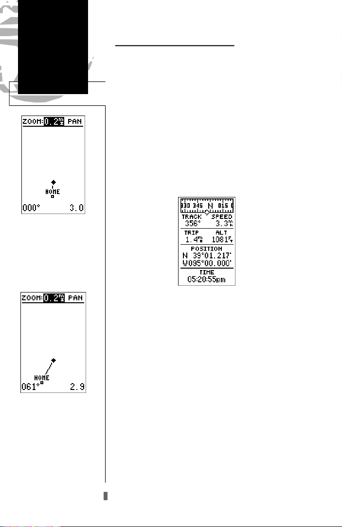
Map Page
The map page displays your
present position as a diamond icon and provides a
real time graphic ‘bre a dcrumb’ display of your track
right on screen.
Using the Position and Map Pages
Now that you’ve marked a position, it’s time to take a
brisk walk using the position and moving map pages to
watch your every move. To get the most from this tutorial,
you will need to walk for at least the time stated in the
below steps. Since the GPS system has a margin of error of
15 meters, this will ensure you travel far enough to register
useful information. You’ll also get a much better indication
of how the GPS 40’s steering guidance and mapping features work to guide you wherever you go.
1. Walk in a straight line for 3-4 minutes at a fast pace and
watch the position page. You can time your distance with
the on-screen clock.
The direction you are moving (your track) and your
speed are displayed on the upper part of the screen, just
below the graphic compass display. The latitude, longitude
and approximate altitude of your position--along with a
resettable trip odometer--are continuously displayed in the
middle of the page, with the time of day displayed below.
Now let’s change the display to the moving map page
and watch the track log of our walk:
The moving map’s default
setting is track up orientation. “Track up” means that
your current direction of
travel is always up (or
t o w a rds the top of) the
screen. It can also be set for
north up, or desired track
up orientation through the
map setup page.
12
1. Press the Pkey to change from the position page to
the map page.
Your current position is shown as the diamond in the
middle of the screen. The dark circle below the diamond
represents the position you created, with the line between
the two showing your track.
1. Turn 90º to your right and continue walking at a fast pace
for another 2-3 minutes. Notice how the display changes,
always keeping the direction you are moving at the top of
the map.
Getting Started
Going To a Waypoint
Once you’ve stored a waypoint in memory, you can use
the GPS 40 to guide you to it by performing a simple
GOTO. A GOTO is really nothing more than the receiver
drawing a straight-line course from your present position to
the destination you’ve selected. To see how it works, let’s
try navigating back to our starting position, the HOME
waypoint.
To select a GOTO destination:
1. Press the Gkey.
2. The GOTO waypoint page will appear, displaying all the
waypoints in memory in alphabetical order.
3. Use Uor Dto highlight the ‘HOME’ waypoint.
4. Press the Ekey to confirm that you want to navigate
to the displayed waypoint.
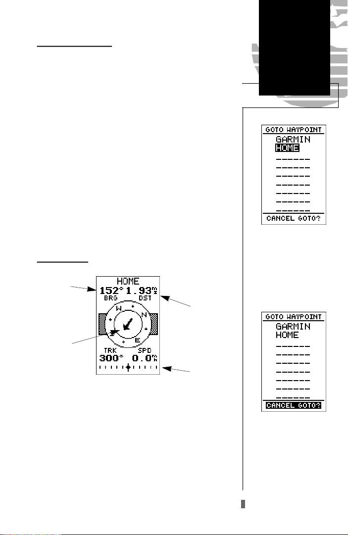
Compass Page
Bearing to
Waypoint
Distance to
Waypoint
GOTO/
Compass Page
The GOTOwaypoint page
allows you to select your
destination from a list of all
available waypoints in the
GPS 40’s memory.
Pointer to
Waypoint
CDIScale
Whenever you select a destination waypoint, the GPS
40 will provide graphic steering guidance with the compass
page. As you begin walking again, the compass page will
display nav data and graphic steering guidance to the destination. The bearing (BRG) and distance (DST) to the waypoint are displayed at the top of the page, below the destination waypoint field. The distance displayed is always the
straight-line-distance from your present position to the destination waypoint. The bearing indicates the exact compass
heading from you to the destination.
Once a GOTO is activated,
the GPS 40 will pro v i d e
steering guidance to the destination until the GOTO is
cancelled. To cancel a
GOTO, highlight the cancel
prompt at the bottom of the
page and press ENTER.
13
Getting Started
Steering
Guidance
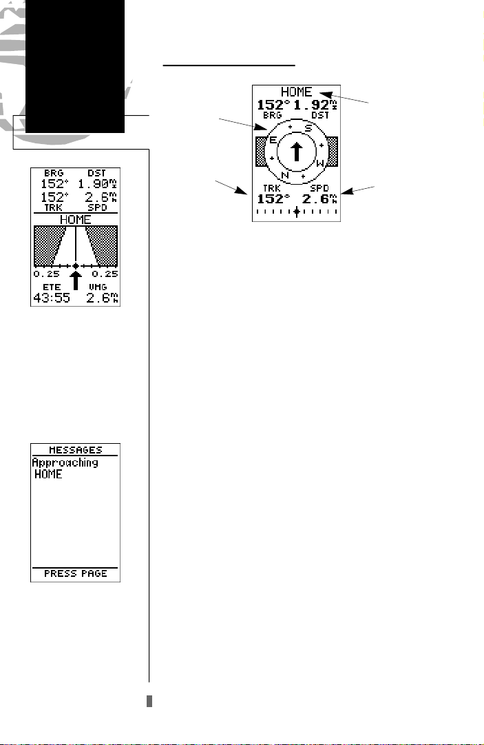
Highway Page
The GPS 40 will also provide steering guidance with
a graphic highway page. To
change the display from the
compas s to the highway
page, press ENTER twice.
Message Page
Once you are one minute
from the destination (based
on your present speed and
course), an arrival message
will be appear on the message page.
14
Compass Page (continued)
Destination
Graphic
Compass
Track Over
Ground
Waypoint
Speed Over
Ground
The middle of the compass page features a rotating “compass” which shows your current cardinal heading while you’re
moving (track up), with a pointer- a rrow in the center to indicate the direction of the destination relative to the dire c t i o n
you are moving. The compass and pointer- a rrow work
together to provide a picture of the direction you are moving
and the direction of the destination at a glance.
The bottom of the compass page displays your curre n t
track (TRK) and speed (SPD) over the ground, while the CDI
(course deviation indicator) scale shows how far you are off
course. The diamond in the center of the CDI scale re p re s e n t s
your present position, while the d-bar (the moving vert i c a l
line on the scale) indicates the direction and distance you are
o ff the desired straight line course.
To stay on course, simply steer toward the d-bar until it is
c e n t e red on the position diamond. The default setting of the
CDI scale is +/- 0.25 miles, with each mark re p resenting 0.05
miles of course deviation. If you do get off course by more
than the selected scale, an arrow prompt will appear at the
end of the scale to indicate the direction you are off course.
For more information on setting the CDI scale, see page 47.
When you are one minute away from the destination
(based on current speed and track over the ground), the GPS
40 will alert you with a flashing on-screen message box.
To view a message:
1. Press the Pkey when the message box appears.
2. Press Pagain to return to the previous page.
When the DST field displays a distance of 0.00 miles,
you’ve reached your destination!
Getting Stared
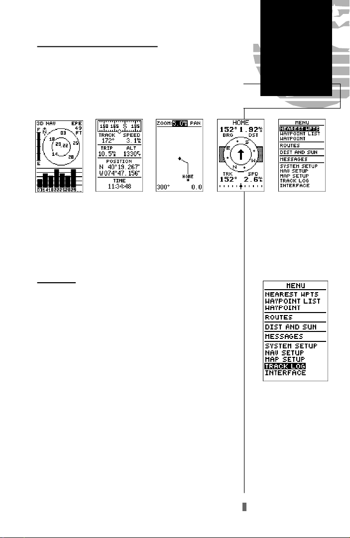
Scrolling Through the Main Pages
Now that you’ve arrived ‘HOME’, let’s take a minute to
see how the GPS 40’s main pages work together. The GPS
40 features five main pages, which are linked together in a
chain. You can quickly scroll through the pages in either
d i rection using the Pand Qkeys.
1. Press the Pkey to scroll through the five main pages
in sequence.
2. Press the Qkey to scroll through pages in the opposite direction.
Menu Page
You’ve already seen the first four pages in action by
acquiring satellites, marking a position and navigating to a
destination. The last page available from the main page
sequence is the menu page, which provides access to the
GPS 40’s waypoint management, route, track log and setup
features. The 11 submenus are divided into categories by
function.
Page Sequence/
Menu Page
To select a submenu from the menu page:
1. Press Por Quntil the menu page appears.
2. Use the Uor Dkeys to highlight the submenu you
want to view.
3. Press Eto access the submenu.
Menu Page
Use the UP and DOWN
keys to select a submenu
from the menu page. Press
ENTER to access the selected submenu.
15

Getting Started
Track Log/
Power Off
Highlight the CLEARLOG?
prompt and press ENTERto
clear the track log. Once all
768 points are used, the oldest point will be continuously deleted to make room for
the latest track log point.
Clearing the Track Log
After you’ve used the GPS40 for a few trips, you may
find that your map display has become a bit messy from
keeping track of your every move. To get a feel for how the
menu page works, let’s clear the track log (the plot points
left on the map page) we’ve just created during the Getting
Started tour.
1. Press Por Quntil the menu page appears.
2. Use theDkey to move the field highlight to the
‘TRACKLOG’ option.
3. Press Eto access the track log page.
4. Press theUkey twice to highlight the ‘CLEARLOG?’
option. The clear log confirmation page will appear.
5. Use the Lkey to highlight the ‘Yes’ prompt.
6. Press Eto finish.
Turning the Receiver Of f
You’ve now gone through the basic operation of your
new GPS 40 and probably know a little more than you
think about how it works. We encourage you to experiment
with the GPS 40 until it becomes an extension of your own
navigation skills. If you encounter any problems using the
unit or want to take advantage of the GPS 40’s more
advanced features, refer to the reference section.
To turn the GPS 40 off:
Confirm the track log warning page to clear the log.
16
1. Press and hold the Bkey for 3 seconds.
Thank you for choosing the GPS 40. We hope it will be
a valuable tool for you wherever you travel.
Reference
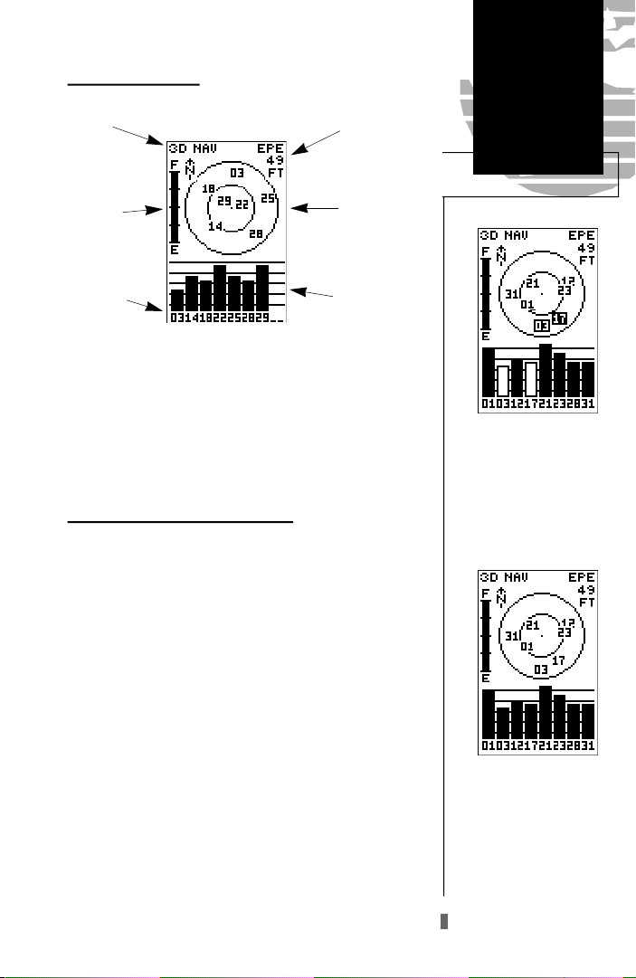
Satellite Status Page
Status
Battery
Indicator
Satellite
Number
Horizontal
Accuracy
Satellite
Sky View
Signal Strength
Indicators
The GPS 40 satellite status page displays the status of
various receiver functions. The status information will help
you understand what the GPS is doing at any given time,
and tell you whether or not the receiver has calculated a
position fix.
Sky View and Signal Strength Bars
The sky view and signal strength bars give you an indication of what satellites are visible to the receiver, whether
or not they are being used to calculate a position fix, and
the signal quality. The sky view in the center of the page
shows a bird’s-eye view of the position of each satellite relative to the receiver’s last known position. The outer circle
represents the horizon (north up); the inner circle 45º
above the horizon; and the center point a position directly
overhead.
When the receiver is looking for a particular satellite,
the corresponding signal strength bar will be blank and the
sky view indicator will remain highlighted in reverse video.
Once the receiver has found the satellite, a hollow signal
strength bar will appear, indicating that the satellite has
been found and the receiver is collecting data from it. The
satellite number in the sky view will also change from
reverse video to normal presentation. As soon as the GPS
40 has collected the necessary data to use the satellite for
positioning, the hollow bar will become solid.
Satellite
Status Page
Satellites in view but not
currently in use (03 & 17)
will be displayed in reverse
video, with the corresponding signal strength bar
‘hollow’.
Once a satellite in view is
usable for positioning, the
satellite number will change
from reverse video and the
signal strength bar will
become solid.
17
 Loading...