

Garmin echoMAP CHIRP 95sv, echoMAP CHIRP 94sv, echoMAP CHIRP 93sv, echoMAP CHIRP 92sv, echoMAP CHIRP 75sv Installation Instructions
...Page 1
echoMAP™ CHIRP
70/90 Series
Installation Instructions
Important Safety Information
WARNING
See the Important Safety and Product Information guide in the
product box for product warnings and other important
information.
When connecting the power cable, do not remove the in-line
fuse holder. To prevent the possibility of injury or product
damage caused by fire or overheating, the appropriate fuse
must be in place as indicated in the product specifications. In
addition, connecting the power cable without the appropriate
fuse in place voids the product warranty.
CAUTION
Always wear safety goggles, ear protection, and a dust mask
when drilling, cutting, or sanding.
NOTICE
When drilling or cutting, always check what is on the opposite
side of the surface.
To obtain the best performance and to avoid damage to your
boat, install the device according to these instructions.
Read all installation instructions before proceeding with the
installation. If you experience difficulty during the installation,
contact Garmin® Product Support.
Software Update
You may need to update the device software when you install
the device or add an accessory to the device.
Loading the New Software on a Memory Card
You must copy the software update to a memory card using a
computer that is running Windows® software.
NOTE: You can contact Garmin customer support to order a
preloaded software update card if you do not have a computer
with Windows software.
Insert a memory card into the card slot on the computer.
1
Go to www.garmin.com/support/software/marine.html.
2
Select Download next to the software bundle that
3
corresponds with your device.
Read and agree to the terms.
4
Select Download.
5
If necessary, select Run.
6
If necessary, select the drive associated with the memory
7
card, and select Next > Finish.
Updating the Device Software
Before you can update the software, you must obtain a
software-update memory card or load the latest software onto a
memory card.
Turn on the chartplotter.
1
After the home screen appears, insert the memory card into
2
the card slot.
NOTE: In order for the software update instructions to
appear, the device must be fully booted before the card is
inserted.
Follow the on-screen instructions.
3
Wait several minutes while the software update process
4
completes.
When prompted, leave the memory card in place and restart
5
the chartplotter manually.
Remove the memory card.
6
NOTE: If the memory card is removed before the device
restarts fully, the software update is not complete.
Registering Your Device
Help us better support you by completing our online registration
today.
• Go to http://my.garmin.com.
• Keep the original sales receipt, or a photocopy, in a safe
place.
Contacting Garmin Product Support
• Go to www.garmin.com/support for in-country support
information.
• In the USA, call 913-397-8200 or 1-800-800-1020.
• In the UK, call 0808 238 0000.
• In Europe, call +44 (0) 870 850 1241.
Tools Needed
• Drill and drill bits
• #2 Phillips screwdriver
• Jigsaw or rotary tool
• File and sandpaper
• Marine sealant (optional)
Mounting Considerations
The device can be mounted using the included bracket, or it can
be mounted flush with the dashboard using a flush-mount kit
(may be sold separately).
Before permanently installing any part of your device, you
should plan the installation by determining the location of the
various components.
• The mounting location must provide a clear view of the
screen and access to the keys on the device.
• The mounting location must be sturdy enough to support the
device and the mount.
• The cables must be long enough to connect the components
to each other and to power.
• The cables can be routed under the bail mount or behind the
device.
• To avoid interference with a magnetic compass, the device
should not be installed closer to a compass than the
compass-safe distance value listed in the product
specifications.
December 2015
Printed in Taiwan 190-01952-02_0A
Page 2
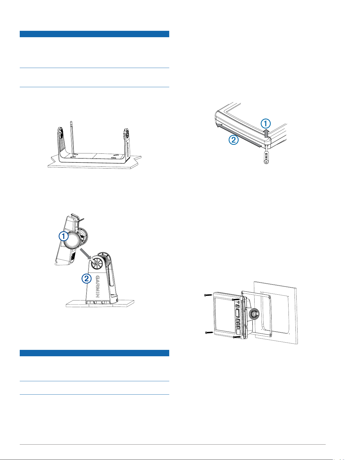
Bail Mounting the Device
NOTICE
If you are mounting the bracket on fiberglass with screws, it is
recommended to use a countersink bit to drill a clearance
counterbore through only the top gel-coat layer. This will help to
avoid any cracking in the gel-coat layer when the screws are
tightened.
Stainless-steel screws may bind when screwed into fiberglass
and overtightened. Garmin recommends applying an anti-seize
lubricant to the screws before installing them.
Select the mounting hardware appropriate for your mounting
1
surface and for the bail-mount bracket.
Using the bail-mount bracket as a template, mark the pilot
2
holes through the screw holes.
Using a drill bit appropriate for the mounting hardware, drill
3
the four pilot holes.
Using the selected mounting hardware, secure the bail-mount
4
bracket to the mounting surface.
Install the bail-mount knobs À on the sides of the device.
5
Using a 9.5 mm (3/8 in.) drill bit, drill one or more of the holes
3
inside the corners of the solid line on the template to prepare
the mounting surface for cutting.
Using a jigsaw or rotary cutting tool, cut the mounting surface
4
along the inside of the solid line indicated on the template.
Place the device into the cutout to test the fit.
5
If necessary, use a file and sandpaper to refine the size of
6
the hole.
If your device has trim caps, use a pry tool, such as a flat
7
piece of plastic or a screwdriver, to carefully pry up the
corners of the trim caps À, slide the pry tool to the center Á,
and remove the trim caps.
Ensure the mounting holes on the device line up with the pilot
8
holes on the template.
If the mounting holes on the device do not line up with the
9
pilot holes on the template, mark the new pilot-hole locations
on your template.
Using a 3.2 mm (1/8 in.) drill bit, drill the pilot holes.
10
Remove the template from the mounting surface.
11
If you will not have access to the back of the device after you
12
mount it, connect all necessary cables to the device before
placing it into the cutout.
NOTE: To prevent corrosion of the metal contacts, cover
unused connectors with weather caps.
Install the rubber gasket pieces on the back of the device.
13
The pieces of the rubber gasket have adhesive on the back.
Make sure you remove the protective liner before installing
them on the device.
Place the device into the cradle Á.
6
Place the cradle in the bail-mount bracket and tighten the
7
bail-mount knobs.
Flush Mounting the Device
NOTICE
Be careful when cutting the hole to flush mount the device.
There is only a small amount of clearance between the case and
the mounting holes, and cutting the hole too large could
compromise the stability of the device after it is mounted.
Using a metal pry tool such as a screwdriver can damage the
trim caps and the device. Use a plastic pry tool when possible.
You can mount the device in your dashboard using the flushmount template and appropriate hardware.
Trim the template and make sure it fits in the location where
1
you want to mount the device.
Secure the template to the mounting location.
2
2
Securely connect each cable to a port on the cradle.
14
Place the device into the cutout.
15
Secure the device to the mounting surface using the included
16
screws.
Install the trim caps by snapping them in place around the
17
edges of the device.
Installing the Cables and Connectors
Wiring to Power
Route the power cable from the swivel mount to the boat
1
battery or fuse block.
Page 3

If necessary, extend the wires using 0.82 mm2 (18 AWG) or
2
larger wire.
Connect the red wire to the positive terminal on the battery or
3
fuse block, and connect the black wire to the negative
terminal.
Connecting the Device to a Transducer
Go to www.garmin.com or contact your local Garmin dealer to
determine the appropriate type of transducer for your needs.
Follow the instructions provided with your transducer to
1
correctly install it on your boat.
Route the transducer cable to the back of your device, away
2
from sources of electrical interference.
Connect the transducer cable to the appropriate port on your
3
device.
Connecting the Cables to the Cradle
The connectors on the cables are keyed to fit only in the correct
ports on the device or cradle.
Compare the divots À on each cable connector to the keying
1
on each port to determine which cable corresponds to each
port.
NMEA 2000® Considerations
NOTICE
If you have an existing NMEA 2000 network on your boat, it
should already be connected to power. Do not connect the
NMEA 2000 power cable to an existing NMEA 2000 network,
because only one power source should be connected to a
NMEA 2000 network.
If you are installing a NMEA 2000 power cable, you must
connect it to the boat ignition switch or through another in-line
switch. NMEA 2000 devices will drain your battery if the NMEA
2000 power cable is connected to the battery directly.
NMEA 2000 compatible models can connect to a NMEA 2000
network on your boat to share data from NMEA 2000 compatible
devices such as sensors or a VHF radio. The necessary NMEA
2000 cables and connectors are sold separately.
If you are unfamiliar with NMEA 2000, you should read the
“NMEA 2000 Network Fundamentals” chapter of the Technical
Reference for NMEA 2000 Products. To download this
document, go to www.garmin.com and select Manuals on the
product page for your device.
The port labeled NMEA 2000 on the back of the device is used
to connect it to a standard NMEA 2000 network.
NOTE: Models that are not directly NMEA 2000 compatible
require the included 4-pin adapter cable to connect to the NMEA
2000 network.
Securely connect each cable to a port.
2
Installing the Device in the Cradle
If your device uses a cradle and you have connected the cables
to the cradle, you can quickly place the device in the cradle
without plugging in any cables.
Place the base of the device in the bottom of the cradle.
1
Tilt the device toward the cradle until it fastens in place.
2
There is an audible click when the device is secured in the
cradle.
Removing the Device from the Cradle
Press the release lever À on the cradle until the device is
1
released.
Tilt the device forward, and lift it out of the cradle.
2
Item Description
À
Á
Â
Ã
Ä
Å
Æ
Ç
NMEA 2000 compatible Garmin device
NMEA 2000 drop cable
NMEA 2000 power cable
Ignition or in-line switch
12 Vdc power source
NMEA 2000 terminator or backbone cable
NMEA 2000 T-connector
NMEA 2000 terminator or backbone cable
Wiring Harness
• The wiring harness connects the device to power and NMEA
0183 devices.
• The device has one internal NMEA 0183 port that is used to
connect to NMEA 0183 compliant devices.
• If it is necessary to extend the power and ground wires, you
must use 0.82 mm2 (18 AWG) or larger wire.
• If it is necessary to extend the NMEA 0183 or alarm wires,
you must use .33 mm2 (22 AWG) wire.
®
3
Page 4

Item Wire Function Wire Color
+
-
NMEA 0183 internal port Rx (in) Brown
À
NMEA 0183 internal port Tx (out) Blue
Á
Ground (power and NMEA 0183) Black
Â
Power Red
Ã
Connecting the Wiring Harness to Power
Route the wiring harness to the power source and to the
1
device.
Connect the red wire to the positive (+) battery terminal, and
2
connect the black wire to the negative (-) battery terminal.
NMEA 0183 Connection Considerations
• The installation instructions provided with your NMEA 0183
compatible device should contain the information you need to
identify the transmitting (Tx) and receiving (Rx) A (+) and B
(-) wires.
• When the device is mounted in a location that prevents the
internal antenna from acquiring a satellite signal, you can
connect an external GPS19x antenna through a NMEA 0183
connection. For more information, see the GPS 19x NMEA
0183 Installation Instructions.
NMEA 0183 Connection Diagram
Item Description
À
Á
Â
Item Garmin Wire
Ê
Ë
Ì
Í
Î
12 Vdc power source
Wiring harness
NMEA 0183 compliant device
Function
Power Red Power
Ground Black Data ground
Tx/Rx Tx/Rx/B (-)
Tx Blue Rx/A (+)
Rx Brown Tx/A (+)
Garmin Wire
Color
NMEA 0183 Device Wire
Function
Specifications
Device Specification Measurement
echoMAP CHIRP 70Dimensions (W x H x D)25 x 13.9 x 5.1 cm (9.8 x
Display size (W x H) 15.2 x 9.1 cm (6.0 x
Weight 0.77 kg (1.7 lbs.)
Power input From 9 to 18 Vdc
Max. power usage 17 W
Compass-safe distance 65 cm (25.6 in.)
echoMAP CHIRP 90Dimensions (W x H x D)28.8 x 16.3 x 5.1 cm (11.3
Display size (W x H) 19.8 x 11.2 cm (4.4 x
Weight 1 kg (2.3 lbs.)
Power input From 9 to 18 Vdc
Max. power usage 20 W
Compass-safe distance 65 cm (25.6 in.)
All Models Temperature range From -15 to 55°C (from 5
Material Polycarbonate plastic
5.5 x 2 in.)
3.6 in.)
x 6.4 x 2 in.)
7.8 in.)
to 131°F)
Device Specification Measurement
Water rating* IEC 60529 IPX7
Transmit power
(RMS)**
Maximum depth*** 701 m (2,300 ft) at 77 kHz
Frequencies**** • Traditional: 50, 77, 83,
500 W
or 200 kHz
• CHIRP DownVü: 260,
455, or 800 kHz
• CHIRP SideVü: 260,
455, or 800 kHz
*The device withstands incidental exposure to water of up to 1 m
for up to 30 min. For more information, go to www.garmin.com
/waterrating.
**Dependent upon transducer rating and depth.
***Maximum depth, dependent upon transducer, water salinity,
bottom type, and other water conditions.
****Dependent upon echoMAP model.
NMEA 2000 PGN Information
Type PGN Description
Transmit and receive 059392 ISO acknowledgment
059904 ISO request
060928 ISO address claim
126208 NMEA: Command, request, and
126996 Product information
127250 Vessel heading
128259 Speed: Water referenced
128267 Water depth
129539 GNSS DOPs
129799 Radio frequency, mode, and power
130306 Wind data
130312 Temperature
Transmit 126464 Transmit and receive PGN list group
127258 Magnetic Variance
129025 Position: Rapid update
129026 COG and SOG: Rapid update
129029 GNSS position data
129283 Cross track error
129284 Navigation data
129285 Navigation route and waypoint info
129540 GNSS satellites in view
Receive 127245 Rudder
127250 Vessel heading
127488 Engine parameters: Rapid update
127489 Engine parameters: Dynamic
127493 Transmission parameters: Dynamic
127498 Engine parameters: Static
127505 Fluid level
129038 AIS class A position report
129039 AIS class B position report
129040 AIS class B extended position report
129794 AIS class A static and voyage related
129798 AIS SAR aircraft position report
129802 AIS safety-related broadcast message
129808 DSC call information
130310 Environmental parameters
130311 Environmental parameters (obsolete)
acknowledge group function
function
data
4
Page 5

Type PGN Description
130313 Humidity
130314 Actual pressure
130576 Small craft status
This data applies only to NMEA 2000-compatible products.
NMEA 0183 Information
Type Sentence Description
Transmit GPAPB APB: Heading or track controller
GPBOD BOD: Bearing (origin to
GPBWC BWC: Bearing and distance to
GPGGA GGA: Global positioning system
GPGLL GLL: Geographic position
GPGSA GSA: GNSS DOP and active
GPGSV GSV: GNSS satellites in view
GPRMB RMB: Recommended minimum
GPRMC RMC: Recommended minimum
GPRTE RTE: Routes
GPVTG VTG: Course over ground and
GPWPL WPL: Waypoint location
GPXTE XTE: Cross track error
PGRME E: Estimated error
PGRMM M: Map datum
PGRMZ Z: Altitude
SDDBT DBT: Depth below transducer
SDDPT DPT: Depth
SDMTW MTW: Water temperature
SDVHW VHW: Water speed and heading
Receive DPT Depth
DBT Depth below transducer
MTW Water temperature
RMC/GGA/GLL GPS position
VHW Water speed and heading
WPL Waypoint location
DSC Digital selective calling
DSE Expanded digital selective calling
HDG Heading, deviation, and variation
HDM Heading, magnetic
MWD Wind direction and speed
MDA Meteorological composite
MWV Wind speed and angle
VDM AIS VHF data-link message
You can purchase complete information about National Marine
Electronics Association (NMEA) format and sentences from: NMEA,
Seven Riggs Avenue, Severna Park, MD 21146 USA (www.nmea.org)
(autopilot) sentence "B"
destination)
waypoint
fix data
(latitude and longitude)
satellites
navigation information
specific GNSS data
ground speed
information
Garmin® and the Garmin logo are trademarks of Garmin Ltd. or its subsidiaries, registered
in the USA and other countries. echoMAP™ is a trademark of Garmin Ltd. or its
subsidiaries. These trademarks may not be used without the express permission of
Garmin.
NMEA® and NMEA 2000® are registered trademarks of the National Marine Electronics
Association. The microSD™ logo is a trademark of SD-3C, LLC.
5
Page 6

© 2015 Garmin Ltd. or its subsidiaries www.garmin.com/support
 Loading...