

Garmin 50 User Manual

GPS 50
PERSONAL NAVIGATOR
OWNER'S MANUAL
TM
GARMIN International, Inc.

GPS 50
Personal Navigator
OWNER'S MANUAL
(for Software Version 2.0 or above)
TM

© 1991-1992 GARMIN, 9875 Widmer Road, Lenexa, KS 66215
Printed in Taiwan.
All rights reserved. No part of this manual may be reproduced or transmitted
in any form or by any means, electronic or mechanical, including photocopying
and recording, for any purpose without the express written permission of
GARMIN.
Information in this document is subject to change without notice. GARMIN
reserves the right to change or improve their products and to make changes
in the content without obligation to notify any person or organization of such
changes or improvements.
October, 1992 190-00015-01 Rev. B

PREFACE
GARMIN thanks you for selecting our high performance, full featured
Personal NavigatorTM. The GPS 50 represents our continued commitment to
provide you with a portable navigation unit that is versatile, extremely
accurate, and easy to use. We are confident you will enjoy using your unit
for many years to come.
The GPS 50's rugged construction and quality components offer the reliability
demanded by the harshest operating environments. It may be used in marine
and land vehicles, as well as by hunters, hikers, and military forces. The unit
may be operated portably using its own battery pack, or it may use a 5-40 volt
DC external power source for fixed mounted applications. You can even use
a 115- or 230-volt battery charger for planning trips at home.
This manual and accompanying quick reference card provide complete
information on safely operating the GPS 50 to its full potential. Two exciting
practice voyages have been planned for you to practice your navigation skills
using the built-in simulator. Afterwards, try a trip of your own to realize the
value of the GPS 50 as your Personal NavigatorTM. If you have any questions
or comments, our Customer Support Department is eager to serve you.
GARMIN is fully committed to your satisfaction as a customer.
GARMIN International, Inc.
9875 Widmer Road
Lenexa, KS 66215
i

CAUTION
The GPS system is operated by the government of the United States which
is solely responsible for its accuracy and maintenance. The system is under
development and is subject to changes which could affect the accuracy and
performance of all GPS equipment. Although the GPS 50 is a precision
electronic NAVigation AID (NAVAID), any NAVAID can be misused or
misinterpreted, and therefore become unsafe. Use the GPS 50 at your own
risk. To reduce the risk, carefully review and understand all aspects of this
Owner's Manual and thoroughly practice operation using the simulator mode
prior to actual use. When in actual use, carefully compare indications from
the GPS 50 to all available navigation sources including the information from
other NAVAIDs, visual sightings, charts, etc. For safety, always resolve any
discrepancies before continuing navigation.
NOTE: This device complies with Part 15 of the FCC Rules. Operation is
subject to the following two conditions: (1) This device may not cause
harmful interference, and (2) this device must accept any interference
received, including interference that may cause undesired operation.
ii

TABLE OF CONTENTS
CHAPTER PAGE
BASIC FEATURES
1 INTRODUCING THE GARMIN GPS 50 1-1
1.1 Capabilities 1-1
1.2 Operations 1-2
2 GETTING STARTED 2-1
2.1 Front Panel 2-1
2.2 Banners 2-1
2.3 Cursor and Fields 2-3
2.4 Keypad Operation 2-3
2.5 Entering Data 2-5
2.6 Viewing Messages 2-5
2.7 Operating Modes 2-6
3 BASIC OPERATION 3-1
3.1 Power On 3-1
3.2 Satellite Status 3-1
3.3 Present Position 3-2
3.4 AutoStore
3.5 CDI and Navigation Summary 3-4
3.6 Waypoints 3-5
3.7 Nearest Waypoints 3-7
3.8 Navigate to a Waypoint 3-8
3.9 Man Overboard 3-9
3.10 Sample Trip 3-9
TM
3-4
4 UNIT CUSTOMIZATION 4-1
4.1 Setup Menu 4-1
4.2 Operating Mode 4-2
4.3 User Selectable Alarms 4-2
4.4 Backlighting Timeout 4-3
4.5 Audio Settings 4-4
4.6 Navigation Units 4-4
4.7 CDI Scale 4-5
4.8 Magnetic Variation 4-5
iii

4.9 Filter Settings 4-6
4.10 Output 4-7
4.11 Map Datum 4-7
ADVANCED FEATURES
5 NAVIGATION PLANNING 5-1
5.1 Navigation Menu 5-1
5.2 Date and Time 5-1
5.3 Event Timer 5-2
5.4 Trip Planning 5-4
5.5 Sunrise/Sunset 5-4
5.6 Alarm Clock 5-5
6 ROUTES 6-1
6.1 Navigating Using Routes 6-1
6.2 Route Catalog 6-2
6.3 Editing Routes 6-3
6.4 Activating Routes 6-5
6.5 Building Routes Using AutoStore
7 SAMPLE SIMULATED TRIP 7-1
TM
6-7
APPENDICES
A MESSAGES A-1
B NAVIGATION TERMS B-1
B.1 Definitions B-1
B.2 Course To Steer (CTS) B-3
C INSTALLATION AND MAINTENANCE C-1
C.1 Specifications C-1
C.2 Electrical Wiring C-3
C.3 Universal Mount Installation C-4
C.4 Universal Mount Operation C-7
C.5 Battery Pack Operation C-9
C.6 Maintenance C-10
C.7 Customer Support C-11
D MAP DATUMS D-1
E INDEX E-1
iv

CHAPTER 1
INTRODUCING THE GARMIN GPS 50
1.1 CAPABILITIES
The GPS 50 provides a host of powerful capabilities which were previously
found only in much larger systems:
· Performance: State-of-the-art MultiTracTM receiver tracks up to eight
satellites while providing high receiver sensitivity, fast first fix, and
continuous navigation updates.
· Portability: Goes where you go - on sea or land. The built-in simulator
allows you to plan your next trip or hone your navigation skills at home
or in your office.
· Navigation: Illuminated keypad and display provide the navigation
information you need at a glance. Store up to 250 alphanumeric
waypoints and 10 reversible routes. The GOTO function sets an
instantaneous course to the waypoint of your choice. The AutoStore
function helps you build routes as you go. A flashing Message
Annunciator and an audible message tone keep you fully informed of
your navigation status.
· Personalized: Configure your unit the way you like by selecting
nautical units, Course Deviation Indicator (CDI) sensitivity, keypad
and display features, map datums, and interface options.
TM
· Low Power Consumption: Battery Saver operation, which draws
less than 1.1 watts, provides up to ten hours of continuous operation
with four AA size alkaline batteries.
· Man Overboard: The Man Overboard function sets an instantaneous
course to the captured position, providing rapid response to an
emergency situation.
· Trip Planning: Analyze distance and time requirements for your trip.
Compute the time of sunrise and sunset at your destination.
· Alarms: An alarm clock and timer allow the GPS 50 to watch the clock
for you. Arrival, anchor drag, and CDI alerts help you safely navigate
your craft.
· Interfaces: Interface with marine autopilots and graphical plotters.
1-1

We encourage you to read through this manual and experiment using the
built-in simulator. This will help you quickly master the power of the GPS 50.
1.2 OPERATIONS
You may use your GPS 50 for both portable and fixed operations. The unit
may be operated from external AC power using a battery charger, external
5-40 volt DC power using the power/data cable or cigarette lighter adapter,
or using a battery pack.
Handheld Operation:
For handheld operation, the GPS 50 is powered by a AA battery pack which
should be filled with four high quality alkaline batteries commonly found at
retail stores. A rechargeable nicad battery pack is also available for handheld
operation.
In order to track GPS satellites, the unit must be situated with the antenna
pointed straight up and should not be blocked by objects or people (signal
reception through thin fabric such as canvas may be adequate but degraded).
A lanyard is provided to prevent accidental dropping of your GPS 50.
(Connect the lanyard to the eyelet on the back of the unit.)
Fixed Mount Operation:
A universal mount is supplied for swivel or surface mount installation in a
boat. The unit may be operated using vehicle power through the power/data
cable or it may be operated using the battery pack. While using vehicle
power, you may wish to leave the battery pack in the unit. In the event of
vehicle power failure, the GPS 50 will automatically switch to battery power.
In addition to supplying power to the unit, the power/data cable allows you to
interface your GPS 50 with other marine electronic devices such as plotters
or autopilots.
A Marine/RV Remote Antenna is available for installations which require an
external antenna for an unobstructed view of the sky. This weather-proof
antenna includes 30 feet of low-loss antenna cable. The remote antenna has
been constructed to thread onto a standard 1" antenna mount. Antenna
mounts, commonly used to attach VHF radio antennas and Loran-C couplers,
are readily available from your local marine accessories dealer.
A Magnetic Mount Antenna is also available for attaching a remote antenna
to a metallic surface. This weather-proof antenna includes 10 feet of low-loss
antenna cable. A cigarette lighter adapter cable may be used to power the
unit in vehicle applications.
1-2
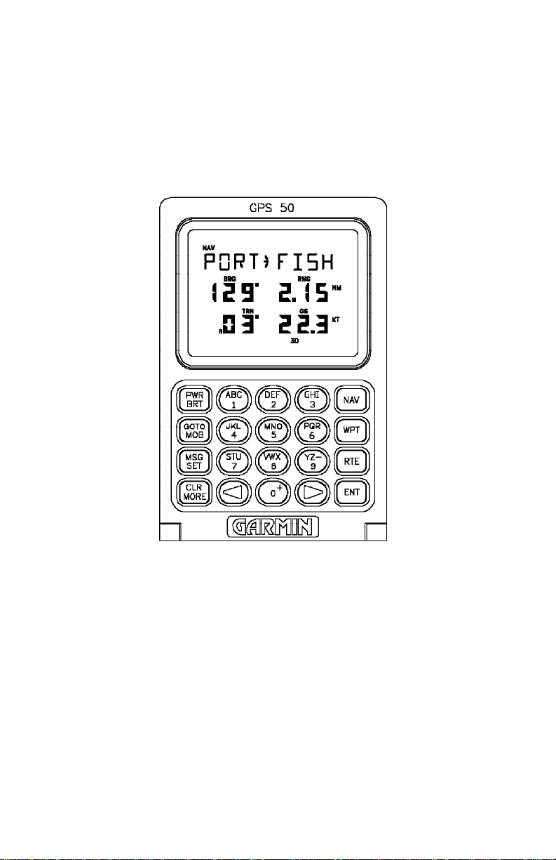
2.1 FRONT PANEL
CHAPTER 2
GETTING STARTED
The front panel consists of a 20-key keypad and a LCD display which
includes three lines of information and various banners. Both the display and
keypad are illuminated for operating in darkness.
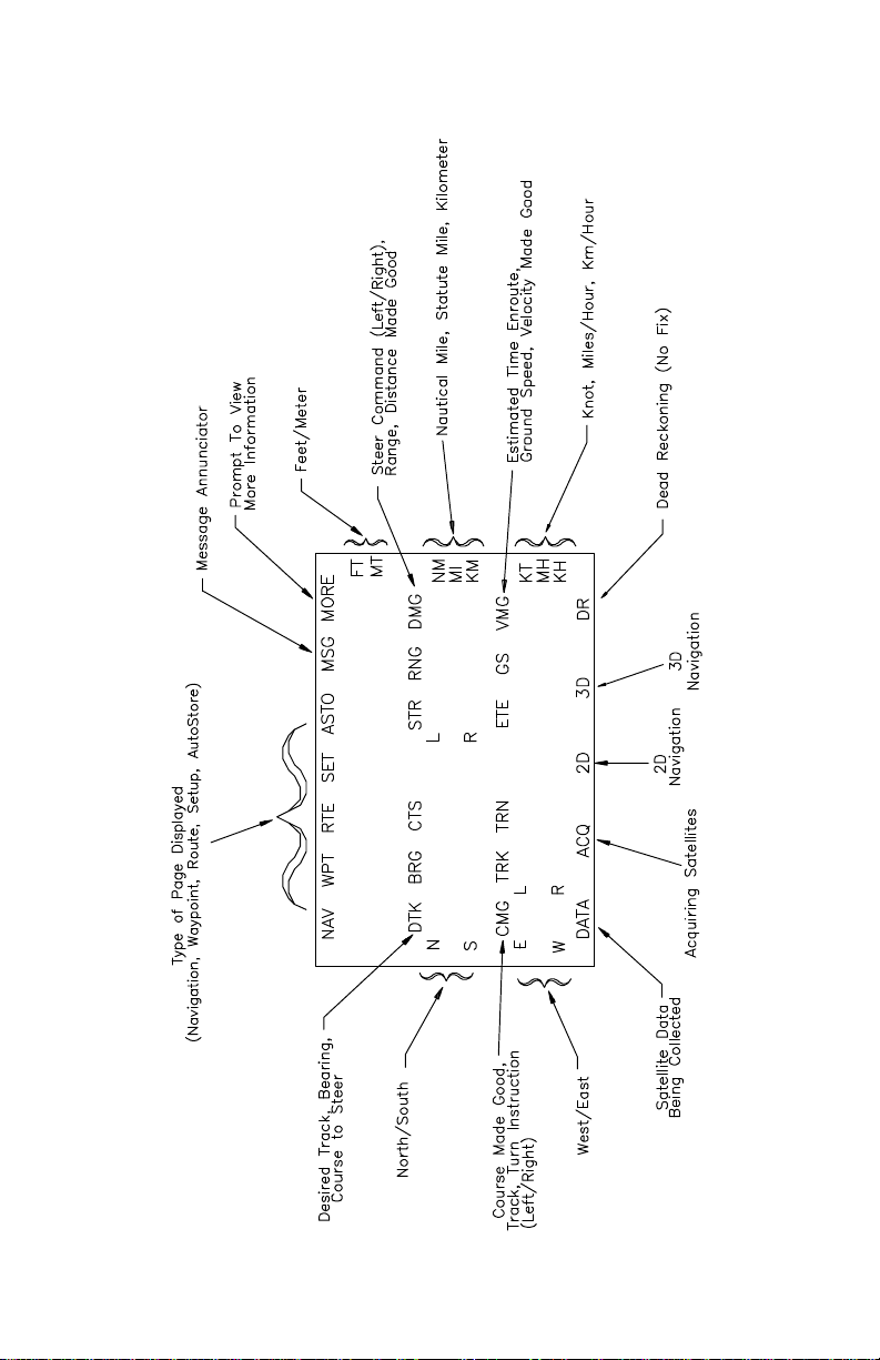
2.2 BANNERS
Information displayed on the LCD is commonly referred to as a “page”. A
page consists of alphanumeric information and banners. Banners, illustrated
below, are used to indicate the type of page, navigation units, and data
displayed (see Appendix B). They also indicate navigation fix type, satellite
tracking, and provide user prompting.
2-1
2-2
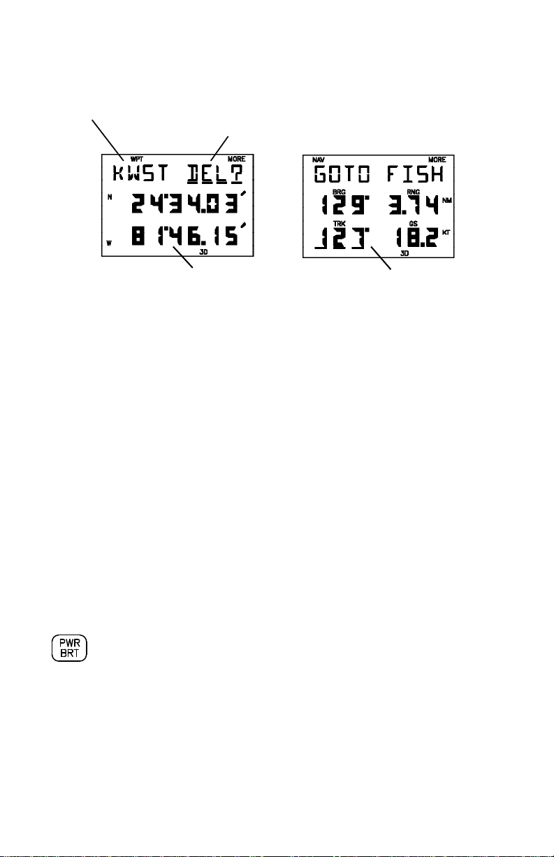
2.3 CURSOR AND FIELDS
Alphanumeric Field Cursor on
Confirmation Field
Numeric Field Cursor on Cyclic Field
The area of the page which is underlined is called the cursor. The cursor
may be moved to locations on the page called fields which allow you to enter
data. You will encounter four types of fields.
· Numeric fields accept numbers. For example, you will enter a
waypoint's latitude in a numeric field.
· Alphanumeric fields accept numbers as well as letters. For example,
you will enter a waypoint's name in an alphanumeric field.
· Cyclic fields allow you to select from one of several available options.
For example, you may select between DTK (desired track), BRG
(bearing to waypoint), or CTS (course to steer) using a cyclic field.
Cyclic fields are indicated on the display by the “MORE” banner.
· Confirmation fields allow you to indicate your approval. For example,
you will be asked to confirm that you want to delete a waypoint.
Confirmation fields always end with a “?” character.
2.4 KEYPAD OPERATION
The PWR/BRT key is a dual function key that controls unit power
and panel backlighting.
When the unit is on, pressing the PWR/BRT key will turn on the
panel backlighting. Pressing the PWR/BRT key again will turn off
the backlighting.
To turn the unit off, press and hold the PWR/BRT key for three
seconds until the display is blank.
2-3
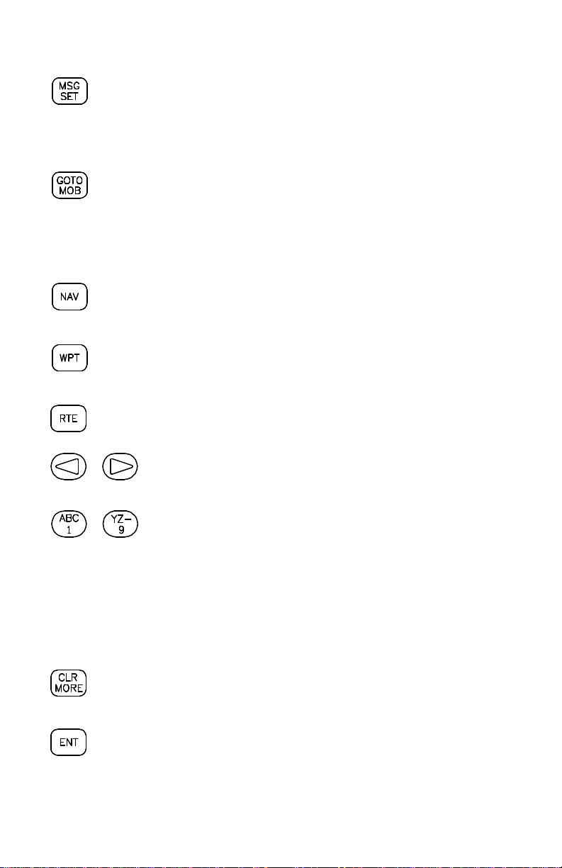
Pressing the MSG/SET key allows you to view new messages
when the "MSG" banner is flashing. (See Section 2.6 and Appendix
A.) Pressing the MSG/SET key also selects the Setup Pages which
allow you to view satellite tracking status and customize the unit as
you like. (See Section 3.2 and Chapter 4.)
Pressing the GOTO/MOB key once allows you to initiate the GOTO
function, which will set an instantaneous course to any waypoint.
(See Section 3.8.) Pressing the GOTO/MOB key twice in succession
allows you to initiate the Man Overboard function, which will set an
instantaneous course to the captured position. (See Section 3.9.)
Pressing the NAV key selects the Navigation Pages which allow
you to view navigation information and perform planning functions.
(See Sections 3.3 and 3.5 and Chapter 5.)
Pressing the WPT key selects the Waypoint Pages which allow you
to create, edit, delete, and rename waypoints. In addition, you may
view your nearest waypoints. (See Sections 3.6 and 3.7.)
Pressing the RTE key selects the Route Pages which allow you to
edit, review, activate, and delete routes. (See Chapter 6.)
Pressing either of the arrow keys allows you to move the
cursor, scroll through information lists, and enter letters of
the alphabet.
2-4
The alphanumeric keys allow you to enter letters and
numbers into the GPS 50.
If you want to enter a number in a numeric field, for instance
“1”, simply press the 1 key. If you want to enter a letter in
an alphanumeric field, for example “A”, press the 1 key to
display B, then press the left arrow key once to select “A”
(you may also press the right arrow key three times to
display the “A”).
Pressing the CLR/MORE key erases information in the
cursor field. If the cursor is over a cyclic field, pressing the CLR/
MORE key will toggle through several available options.
Pressing the ENT key completes the process of data entry. If the
cursor is over a confirmation field, pressing the ENT key indicates
your approval.

2.5 ENTERING DATA
To enter data you must first move the cursor under the desired field by
pressing the right or left arrow key.
To enter a number...
· Press the key that is labeled with the desired number. The numbers
will fill in from the left side of the field similar to a typewriter. You must
enter any leading zeros in the field. For example, if you wish to enter
“51” in a three space field, you must press the 0, 5, and 1 keys in that
order.
· Press the CLR key if you enter an incorrect number.
· Press the ENT key when you have filled all significant digits of the field
with numbers (trailing zeros are automatically filled in by the GPS 50).
To enter a letter...
· Press the key that is labeled with the desired letter.
· Press the right or left arrow key until the desired letter is displayed.
· Press the CLR key if you enter an incorrect letter.
· Press the ENT key when all the characters are entered.
The GPS 50 features a keypad feedback tone which will sound each time you
press a key. If you enter data which is not appropriate for the field, the
feedback tone will quickly sound three times indicating an error. The keypad
feedback tone can be turned off if you wish (see Section 4.5).
2.6 VIEWING MESSAGES
From time to time, the GPS 50 will use a message to tell you of conditions
that need your attention. When the GPS 50 has a new message for you, the
MSG banner will flash. When this occurs, press the MSG key to view new
message(s). Continue to press the MSG key until the page you were viewing
prior to pressing the MSG key is displayed.
While the MSG banner is flashing, the GPS 50 will also generate an audible
tone to alert you of the message (if your unit is connected to an external
alarm, it will also be activated). Messages that demand immediate attention
such as an arrival alarm generate a quick tone that will not stop until you view
the message. All other messages generate a slow tone that will cease after
15 seconds. The message tone may be turned off if you wish (see Section
4.5).
2-5

Important messages will remain on the Message Page after being viewed.
If this occurs, the MSG banner will be in view but will not flash (if no messages
exist, the MSG banner will not be visible). To review these messages, press
the MSG key until the “MESSAGES” title is displayed. Then, press the
MORE key until the “END MSGS” title is displayed.
Refer to Appendix A for a complete list of GPS 50 messages.
2.7 OPERATING MODES
Three modes are available which will allow you to operate your GPS 50 in the
way which best suits your needs (see Section 4.2).
Normal mode is most suitable for high dynamics applications. The GPS 50
will typically operate up to six hours on a single pack of batteries.
Battery Saver mode is suitable for most applications and will extend the
battery life to as much as ten hours.
Simulator mode allows you to simulate the operation of the GPS 50 while
at home or in your office. The simulator mode can be used while learning to
use your GPS 50 and is ideal for planning routes and entering waypoints.
Keep in mind that the GPS 50 is not tracking satellites in the simulator mode.
You should never attempt to use the simulator mode for actual navigation.
If you are using your GPS 50 for the first time, we encourage you to review
Chapter 3 which introduces the GPS 50's basic features. Additionally, you
may wish to review Chapter 4 on custom setups. Afterward, you may want
to read through the rest of this manual and make further use of the built-in
simulator to practice with the advanced features.
2-6

CHAPTER 3
BASIC OPERATION
3.1 POWER ON
After you turn your GPS 50 on, it will conduct a series of self tests and display
the following notices: “VER x.xx”, “COPYRIGHT”, “1991-1992”, and
“GARMIN”. Following completion of the tests, the GPS 50 will begin
acquiring satellites that will typically take two minutes to obtain a position fix.
Initially, the GPS 50 will display the “ACQ” banner; it will inform you when a
position fix is obtained by transitioning to either the “2D” or “3D” banner.
When four or more satellites with good geometry are available, the GPS 50
will automatically operate in the 3D mode in which latitude, longitude, and
altitude are computed. If only three satellites are available, the unit will
operate in 2D mode in which only latitude and longitude are computed. When
operating in the 2D mode, the unit will use the last computed altitude or your
last entered altitude (Section 3.3 describes how you may enter the altitude).
If less than three satellites with acceptable geometry are available, the “DR”
banner will be displayed.
Your GPS 50 will automatically update satellite orbital data as it operates. If
you have not operated your unit for a period of six months or longer, it will take
approximately 12.5 minutes to search the sky and collect new orbital data.
You will be informed when your unit is searching the sky with the message
“SRCH SKY”. Additionally, the “DATA” banner will be displayed. Once
satellite orbital data is collected, it will be stored in battery backed up memory.
This means the data will not be lost when you turn your GPS 50 off.
3.2 SATELLITE STATUS
Satellite DOP
Identifier
Azimuth Elevation Signal Quality
SATELLITE STATUS PAGE
Satellites EPE
Tracked/Visible
3-1

The Satellite Status Page may be displayed by pressing the SET key. This
page shows the number of satellites tracked and visible, dilution of precision
(DOP), and estimated position error (EPE). DOP is a measure of the satellite
geometry quality and hence the relative accuracy of your position (1 meaning
the best and 10 meaning poor). EPE, which is computed using the satellite
geometry (DOP), signal, and data quality, receiver tracking status and other
factors, is an overall measure of your position accuracy. DOP and EPE are
advisory information only.
The Satellite Status Page also shows the identifier (1-32), azimuth, elevation,
and signal quality of up to eight visible satellites. The azimuth is an angle from
000° to 359° which indicates the bearing from the present position to the
satellite, with 000° representing true north. The elevation is an angle from 00°
to 90° which indicates the height of the satellite above the horizon, where 00°
indicates the horizon and 90° indicates a satellite is directly overhead. The
azimuth and elevation are useful for determining whether a satellite signal is
blocked by buildings, mountains, or other obstructions. The signal quality is
a number from 1 through 9, with 9 indicating the strongest signal. If a satellite
is visible but not tracked, the signal quality will be blank.
The Satellite Status Page will automatically display each satellite’s information
for three seconds. You may also manually scroll through the list of visible
satellites.
To manually scroll through the visible satellite list...
· Use an arrow key to move the cursor under the satellite identifier.
· Press MORE to view each visible satellite’s information.
· Press ENT to remove the cursor and return to automatic mode.
3.3 PRESENT POSITION
Altitude
Latitude
Longitude
POSITION PAGE
3-2

The Position Page may be displayed by pressing the NAV key. This page
displays your latitude and longitude relative to the selected earth datum (see
Section 4.11), as well as the altitude above mean sea level (MSL).
When the GPS 50 is performing 2D navigation, the last known altitude will be
used in the latitude/longitude computation. If the altitude is not accurate
within a few hundred feet, you should manually enter your altitude.
To change the altitude...
· Use an arrow key to move the cursor under the altitude.
· Enter the altitude. If your antenna is mounted on a high mast, make
sure you add the mast height. (Remember to complete the data entry
by pressing ENT.)
During initial satellite acquisition, the displayed position is the last computed
position stored in the GPS 50. If your position has moved more than 1000
nautical miles with the power off, you may wish to enter a more accurate initial
position to speed up the acquisition process. (You may also change the
position at any time when you are operating in simulator mode.)
To change the latitude/longitude...
· Use an arrow key to place the cursor under the latitude field.
· Check the hemispheric designation (“N” or “S”) of the latitude. If it is
correct, go to the next step. If it is incorrect, press the CLR key until
the correct hemispheric designation is displayed.
· Enter the latitude (remember to complete the data entry by pressing
ENT).
· Check the hemispheric designation (“E” or “W”) of the longitude. If it
is correct, go to the next step. If it is incorrect, press the CLR key until
the correct hemispheric designation is displayed.
· Enter the longitude (remember to complete the data entry by pressing
ENT).
3-3
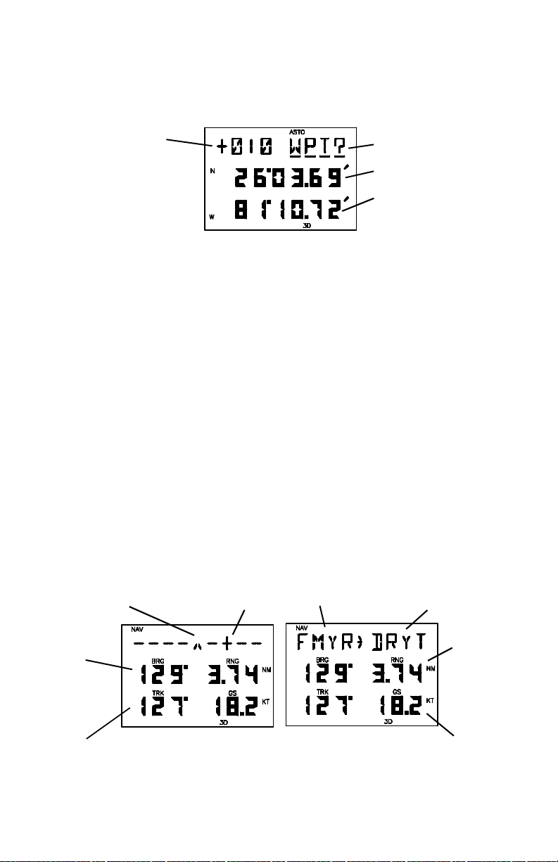
3.4 AUTOSTORE
Waypoint
Name Storage Selection
Latitude
Longitude
AUTOSTORE
TM
PAGE
The AutoStoreTM Page is displayed by pressing the ENT key while viewing
the Position Page. This page allows you to capture your position at the touch
of a button so that you may easily return later. Additionally, you may record
your navigation path by inserting the captured waypoints into a route (see
Section 6.5).
To capture your present position...
· Press NAV until the Position Page is displayed.
· Press ENT. The AutoStoreTM Page will be displayed with the default
waypoint name on line one. The waypoint name begins with a “+”
character followed by a 3-digit number, for example “+010”.
· If you wish to give the waypoint a name of your own, move the cursor
under the waypoint name and enter the name of your choice.
· With the cursor under “WPT?” (the storage selection field), press ENT.
3.5 CDI AND NAVIGATION SUMMARY
Desired Course Your Position “From Waypoint” “To Waypoint”
Direction Distance
(DTK, (STR,
BRG, RNG,
CTS) DMG)
Direction Speed
(CMG, (ETE,
TRK, GS,
TRN) VMG)
(CDI on line 1) (Active leg on line 1)
CDI PAGE
3-4

The CDI Page may be displayed by pressing the NAV key. This page
displays virtually all the information you need to guide your craft.
The CDI (Course Deviation Indicator) is oriented so that the center represents
your desired course and the CDI hash represents your position. You must
steer toward the center of the CDI to eliminate cross track error and stay on
course. The to/from arrow in the center of the CDI indicates if you are
navigating to the waypoint (up arrow) or if you have passed the waypoint
(down arrow). You may set the CDI alarm and CDI scale from the Setup
Pages (see Sections 4.3 and 4.7).
You may select the type of information you wish to see on each line. To make
a change, place the cursor under the field and press the MORE key until the
appropriate information is displayed. (See Appendix B for an illustration and
further explanation of the selectable navigation information on lines two and
three.)
On line one, you may elect to display a CDI or the active leg (see Chapter 6).
On line two, you may select one of three direction options (desired track,
bearing, or course to steer). You may also select one of three distance
options (steer direction and distance, range, or distance made good).
On line three, you may select one of three direction options (course made
good, track, or turn instruction). You may also select estimated time enroute
or one of two velocity options (ground speed or velocity made good).
During the process of acquiring satellites, the GPS 50 will not provide
navigation data. The CDI Page will indicate this condition by displaying “NO
POSN” on line 1 and all navigation data on lines 2 and 3 will be blank. If the
GPS 50 is not navigating to a waypoint, the CDI will indicate this condition by
displaying “NO ACT WP” (no active waypoint) and all navigation data except
speed and track will be blank.
3.6 WAYPOINTS
The GPS 50 allows you to create, store, and use 250 alphanumeric
waypoints. A waypoint consists of a name (up to four letters or numbers), and
its latitude/longitude location. You will have the opportunity to use waypoints
extensively while operating the GPS 50. For example, you can navigate to
a waypoint, build a route using waypoints, and perform trip planning using
waypoints.
3-5
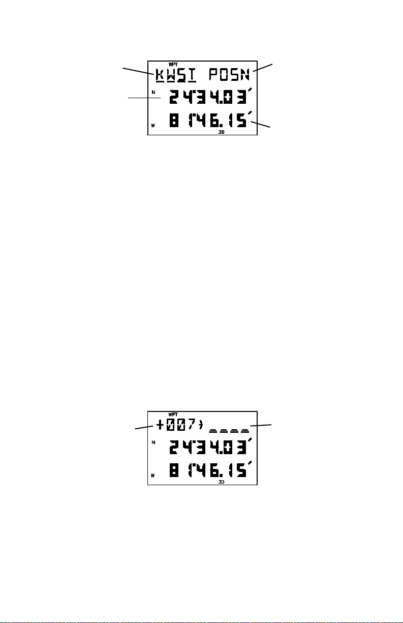
Waypoint View/Action
Name Selection
(POSN, REN, DEL)
Latitude
Longitude
WAYPOINT DEFINITION PAGE
The Waypoint Definition Page may be displayed by pressing the WPT key.
It allows you to review, create, modify, delete, and rename waypoints.
To create, modify, or review a waypoint
· With the cursor under the waypoint name field, enter the desired
waypoint name. (Press the MORE key until “POSN” is displayed if it
is not already displayed under the view/action field.)
· To create or modify position, enter the waypoint latitude and longitude
as described in Section 3.3. (NOTE: If a waypoint is being used for
navigation, its position cannot be modified. An attempt to modify the
position of such a waypoint will result in the message “ACTV WPT”.)
To rename a waypoint...
· With the cursor under the waypoint name field, enter the name of the
waypoint to be renamed.
· Press MORE until “REN?” is displayed.
· Press ENT, the following page will be displayed.
Old New
Waypoint Waypoint
Name Name
· Enter the new waypoint name.
To delete a waypoint from memory...
· With the cursor under the waypoint name field, enter the name of the
waypoint to be deleted.
· Press MORE until “DEL?” is displayed.
3-6

· Press ENT, the waypoint is now deleted from memory. (NOTE: If you
wish to delete a waypoint that is used in a route, first remove it from all
routes before attempting to delete the waypoint. An attempt to delete
a waypoint used in a route will result in the message “ROUTE WPT”.)
A stored waypoint is used by entering its alphanumeric name on a waypoint
name field. (When a waypoint name which does not exist is entered, the error
tone will sound.) As an alternative, the GPS 50 provides a scanning feature
that allows you to select a waypoint by quickly scanning through the entire
list of waypoints in alphabetical order (numbers are ordered before the letters
of the alphabet).
To select a waypoint by scanning...
· With the cursor under a waypoint name field, press WPT. The first
alphanumeric waypoint will be displayed in the waypoint field. (Each
time the Waypoint Definition Page is selected, the scanning mode will
automatically be activated with the first alphanumeric waypoint
displayed. There is no need to press WPT.)
· Use the arrow keys to scan through the entire list of waypoints.
· With the desired waypoint shown, press ENT to select the waypoint
(press CLR to cancel the scanning operation at any time).
Variable rate scanning is implemented to allow you to quickly go through the
list. When the arrow keys are pressed briefly, you step through the waypoints
one at a time. As the arrow keys are held for a longer period of time, the
waypoint list scrolls more rapidly; the longer the arrow keys are held, the
larger the step through the list.
3.7 NEAREST WAYPOINTS
An important feature of the GPS 50 is the ability to display up to nine
waypoints nearest to your position (but not further than 100 nautical miles).
In an emergency, you may use the nearest waypoint feature to find the
closest point of safety in your area.
Rank Waypoint Name
(NR1..NR9)
Bearing From Range From
Present Position Present Position
Estimated Time
Enroute
NEAREST WAYPOINT PAGE
3-7
The Nearest Waypoint Page may be displayed by pressing the WPT key. It
provides the waypoint name and bearing/range/estimated time enroute from
present position. Entire lists of your nearest waypoints (indicated by NR1
through NR9) may be viewed by pressing the MORE key while the cursor is
under the waypoint name.
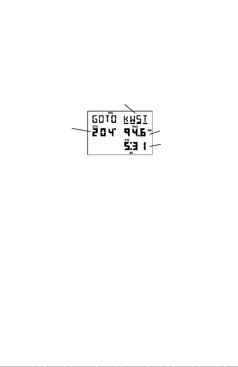
3.8 NAVIGATE TO A WAYPOINT
The GOTO function allows you to quickly set a course from your position to
any waypoint.
GOTO Waypoint
Desired
Track Range
Estimated
Time Enroute
ACTIVE ROUTE PAGE (GOTO MODE)
To activate the GOTO function...
· Press GOTO. The Active Route Page will be displayed with the cursor
under the GOTO waypoint field. If the GPS 50 is currently navigating
to a waypoint, that waypoint will be offered as the default GOTO
waypoint.
· Confirm the default GOTO waypoint by pressing the ENT key (this will
re-center CDI on the CDI page) or enter the desired GOTO waypoint
name. The CDI Page will be displayed.
Alternatively, the GOTO function may be quickly activated from any page
(e.g. the Nearest Waypoint Page) by placing the cursor under the desired
waypoint name and pressing the GOTO key. The Active Route Page will be
displayed with the cursor under the GOTO waypoint name. The GOTO
function will be activated when the ENT key is pressed.
To cancel the GOTO function...
· Press GOTO.
· Press CLR, the GOTO waypoint name will become blank.
· Press ENT. The GPS 50 will start to navigate using the active route,
if it has been programmed (see Chapter 6). Otherwise, the GPS 50 will
cease the computation of all waypoint navigation data.
3-8
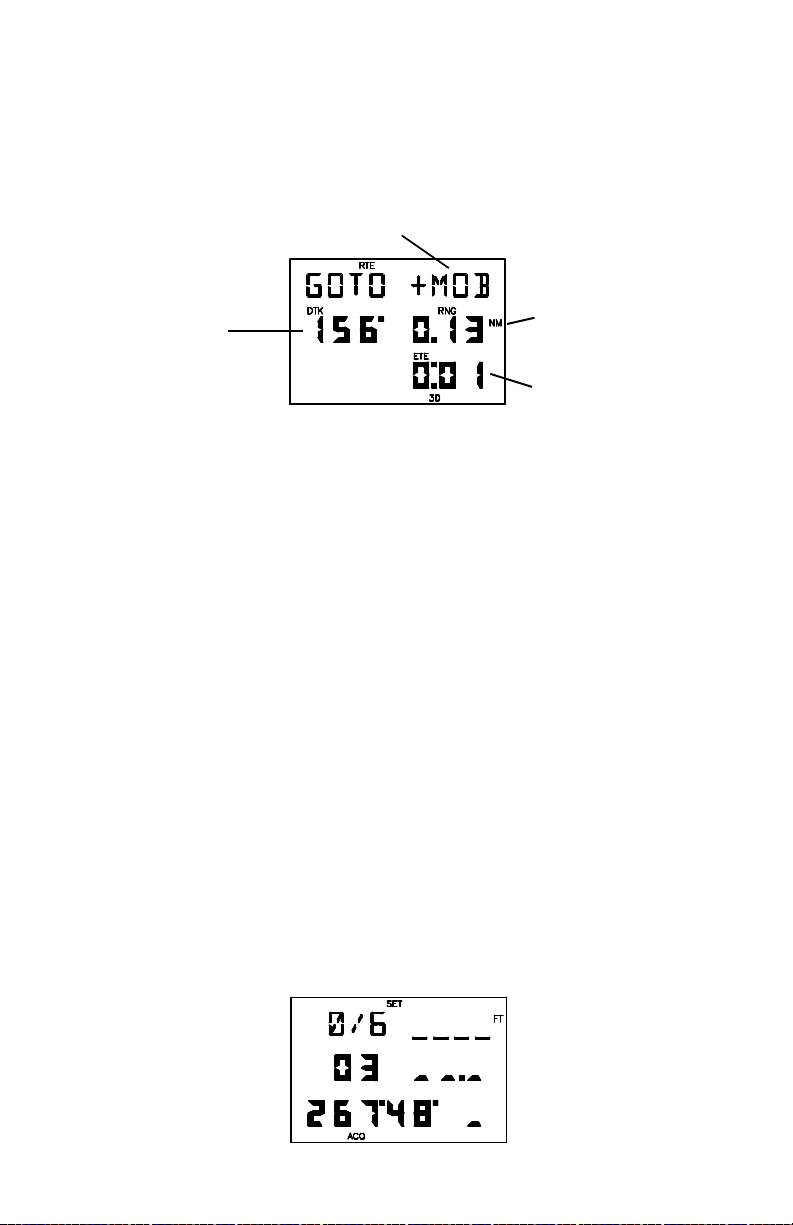
3.9 MAN OVERBOARD
The Man Overboard function allows you to set an instantaneous course to
a captured position, providing rapid response to an emergency situation.
Man Overboard Waypoint
Desired Range
Track
Estimated
Time Enroute
ACTIVE ROUTE PAGE (MAN OVERBOARD MODE)
To activate the Man Overboard function...
· Press MOB twice. The Active Route Page will be displayed and the
present position will be captured in a waypoint named “+MOB”.
· Press ENT to navigate to the Man Overboard waypoint. The CDI Page
with navigation information to “+MOB” will be displayed.
3.10 SAMPLE TRIP
Now that you have gained a basic understanding of the GPS 50, you are
ready to embark on a sample trip! (The sample illustrations in this section
assume that the factory default settings have not been changed. If you have
changed these parameters, the unit may display slightly different data than
presented here.)
Your GPS 50 is factory initialized with a position of N39°, W095°. A waypoint
named GRMN, located at GARMIN’s Lenexa, Kansas facilities, is also
provided (GARMIN is located 109°, 11.8 nautical miles from the initial
position).
Just for fun, let’s go to GARMIN! Turn on your GPS 50. The power on notices
will be displayed followed by the Satellite Status Page as illustrated below.
3-9
 Loading...