

Garmin 155XL, GPS 155XL Maintenance Manual
*36;/
0$,17(1$1&(0$18$/
Garmin International
1200 E. 151
Olathe, KS 66062 USA
190-00067-25 (Rev D) April 1999
st
Street

© Copyright 1999
GARMIN Corporation
All Rights Reserved
Except as expressly provided herein, no part of this manual may be reproduced, copied, transmitted, disseminated, downloaded
or stored in any storage medium, for any purpose without the express prior written consent of GARMIN Corporation. GARMIN
Corporation hereby grants permission to download a single copy of this manual and of any revision to this manual onto a hard
drive or other electronic storage medium to be viewed and to print one copy of this manual or of any revision hereto, provided
that such electronic or printed copy of this manual or revision must contain the complete text of this copyright notice and
provided further that any unauthorized commercial distribution of this manual or any revision hereto is strictly prohibited.
GARMIN
1200 E. 151st Street
Olathe, KS 66062 USA
Telephone: 913-397-8200
Dealer Line: 1-800-800-1420
Website Address: www.garmin.com
REVISION RECORD
REVISION REVISION
DATE
A 06/30/98 INITIAL RELEASE
B 09/15/98 CORRECT TO/FROM FLAG VOLTAGE
C 10/20/98 CORRECT TESTING PARAMETERS
D 04/30/99 REDRAW
DESCRIPTION
ECO #
-----
9396
9871
10935
A 190-00067-25 Rev D

TABLE OF CONTENTS
Section 1
DESCRIPTION AND OPERATION
Paragraph Page
1.1 INTRODUCTION.......................................................................................................1-1
1.2 GENERAL DESCRIPTION.........................................................................................1-1
1.3 DETAILED DESCRIPTION.........................................................................................1-2
1.3.1 Control Display Unit—CDU........................................................................................1-3
1.3.2 Main Board Assembly................................................................................................1-3
1.3.2.1CPU Board.................................................................................................................1-3
1.3.2.2CPU Power Supply Circuits........................................................................................1-4
1.3.3 GPS Receiver............................................................................................................1-5
1.3.4 Interface Board and Data Cards.................................................................................1-6
1.3.5 Altitude Decoder Board..............................................................................................1-6
Section 2
SPECIAL TOOLS AND TEST EQUIPMENT
2.1INTRODUCTION.............................................................................................................2-1
2.2SPECIAL TOOLS AND TEST EQUIPMENT....................................................................2-1
2.3TEST PANEL/TEST HARNESS.......................................................................................2-1
Section 3
TROUBLESHOOTING
3.1 INTRODUCTION.......................................................................................................3-1
3.2 TROUBLESHOOTING EQUIPMENT.........................................................................3-1
3.3 SELF-TEST FAILURES.............................................................................................3-1
3.4 INITIAL TROUBLESHOOTING..................................................................................3-3
3.4.1 Power Supply Check..................................................................................................3-3
3.4.2 Internal Clock Check..................................................................................................3-3
190-00067-25 Rev D i

TABLE OF CONTENTS
(Continued)
3.5 TROUBLESHOOTING............................................................................................... 3-6
3.5.1 Table Notes............................................................................................................... 3-7
3.6 EXTERNAL CONNECTORS...................................................................................... 3-8
3.7 INTERCONNECT DIAGRAM................................................................................... 3-10
Section 4
DISASSEMBLY AND REASSEMBLY
4.1 INTRODUCTION ....................................................................................................... 4-1
4.2 REQUIRED TOOLS................................................................................................... 4-1
4.3 DISASSEMBLING THE UNIT .................................................................................... 4-1
4.3.1 Removing the Covers................................................................................................. 4-1
4.3.2 Control/Display Unit................................................................................................... 4-2
4.3.3 Removing the Altitude Decoder Chassis Subassembly.............................................. 4-2
4.3.4 Interface Board Removal ........................................................................................... 4-2
4.3.5 CPU Board Removal.................................................................................................. 4-3
4.3.6 GPS Receiver Assembly Removal and Disassembly................................................. 4-3
4.3.7 Power Switch Assembly Removal.............................................................................. 4-4
4.3.8 Rotary Switch Assembly Removal ............................................................................. 4-4
4.3.9 Display Module Assembly.......................................................................................... 4-4
4.3.10 Remote Battery Pack and Charger Disassembly ....................................................... 4-5
4.4 REASSEMBLY........................................................................................................... 4-5
Section 5
TESTING
5.1 INTRODUCTION ....................................................................................................... 5-1
5.2 TEST EQUIPMENT.................................................................................................... 5-1
5.3 MEMORY BATTERY REPLACEMENT...................................................................... 5-2
5.4 TESTING...................................................................................................................5-3
5.4.1 Test Setup.................................................................................................................5-3
5.4.2 Test Procedure .......................................................................................................... 5-3
ii
190-00067-25 Rev D

TABLE OF CONTENTS
(Continued)
Section 6
REPLACEABLE PARTS
6.1 INTRODUCTION............................................................................................................. 6-1
Section 7
ASSEMBLY DRAWINGS
7.1 INTRODUCTION............................................................................................................. 7-1
190-00067-25 Rev D iii

LIST OF ILLUSTRATIONS
Figure Page
1-1 GPS 155XL BLOCK DIAGRAM ................................................................................... 1-2
1-2 GPS 155XL CONTROL/DISPLAY UNIT BLOCK DIAGRAM......................................... 1-3
1-3 GPS 155XL MAIN BOARD ASSEMBLY BLOCK DIAGRAM......................................... 1-4
1-4 GPS 155 XL GPS RECEIVER BLOCK DIAGRAM........................................................ 1-5
2-1 TEST HARNESS/TEST SETUP J2............................................................................... 2-2
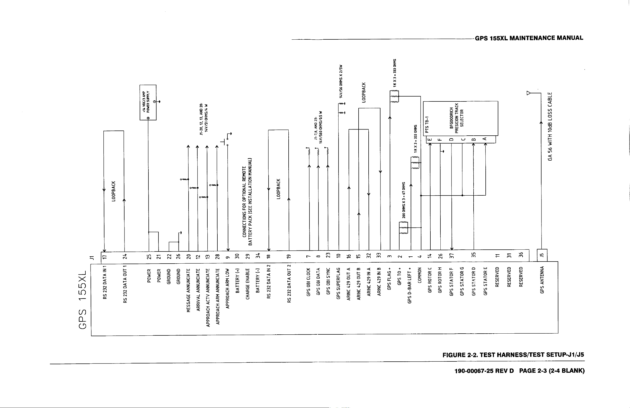
2-2 TEST HARNESS/TEST SETUP J1/J5..........................................................................2-3
3-1 CPU BOARD POWER SUPPLY TEST POINTS (TOP VIEW) ...................................... 3-4
3-2 CPU BOARD TEST POINTS (BOTTOM VIEW)............................................................ 3-5
3-3 GPS 155XL INTERCONNECT DIAGRAM.................................................................. 3-10
5-1 CDI DEFLECTION TEST PAGE...................................................................................5-3
5-2 OBI TEST PAGE .......................................................................................................... 5-5
5-3 I/O TEST PAGE............................................................................................................ 5-6
5-4 ANNUNCIATOR TEST PAGE....................................................................................... 5-6
5-5 EXTERNAL SWITCHES TEST PAGE .......................................................................... 5-7
5-6 ALTITUDE DECODER TEST PAGE............................................................................. 5-8
5-7 OBS SELECTED COURSE TEST PAGE ..................................................................... 5-9
5-8 EXTERNAL POWER/BATTERY TEST PAGE .............................................................. 5-9
5-9 DISPLAY INTENSITY TEST PAGE............................................................................5-10
5-10 GPS RECEIVER TEST PAGE.................................................................................... 5-10
7-1 GPS 155XL ASSEMBLY............................................................................................... 7-3
7-2 GPS 155XL GPS RECEIVER ASSEMBLY................................................................... 7-5
7-3 GPS 155XL MAIN CHASSIS ASSEMBLY .................................................................... 7-7
7-4 GPS 155XL CDU ASSEMBLY...................................................................................... 7-9
7-5 GPS 155XL REMOTE BATTERY PACK..................................................................... 7-11
LIST OF TABLES
Table Page
3-1 SELF-TEST FAILURES ............................................................................................... 3-2
3-2 TROUBLESHOOTING CHART..................................................................................... 3-6
3-3 J1 PINOUT INFORMATION .........................................................................................3-8
3-4 J2 PINOUT INFORMATION..........................................................................................3-9
6-1 REPLACEABLE PARTS............................................................................................... 6-1
iv
190-00067-25 Rev D

SECTION 1
DESCRIPTION AND OPERATION
1.1 INTRODUCTION
This manual provides assembly-level repair information for the GARMIN GPS 155XL. If necessary, the GPS
155XL can be returned to GARMIN for all service work. Contact GARMIN at the following address for further
service information:
GARMIN
1200 E. 151st Street
Olathe, KS 66062 USA
Telephone: 913-397-8200
Dealer Line: 1-800-800-1420
Website Address: www.garmin.com
1.2 GENERAL DESCRIPTION
The GPS 155XL is an aircraft rack-mounted GPS receiver that meets TSO-C129a (Al) requirements for
Instrument Flight Rules (IFR) enroute, terminal, and non-precision approach operations. The unit features a 12
parallel-channel receiver for tracking up to twelve satellites simultaneously. The GPS 155XL provides Course
Deviation Indication (CDI) on an 80 x 240 double supertwisted nematic (DSTN) display. The display also
features automatic contrast adjustment with reverse mode. An optional, remote-mounted recharging battery is
available which provides up to two hours of navigation (with screen time-out enabled) in the event of an aircraft
electrical system failure.
The unit is constructed from high-quality materials and uses the latest techniques in manufacturing technology.
In order to achieve the desired reliability, size and power requirements, surface mount components are used
extensively. Specialized equipment and procedures are required to repair circuit boards using surface-mount
components. GARMIN does not authorize the repair of GPS 155XL circuit boards. All circuit boards and
assemblies for the GPS 155XL can be affordably replaced through the GARMIN board exchange program, if
necessary. The following assemblies and printed circuit boards are field replaceable:
Altitude Decoder Board—Printed circuit board which contains the altitude decoder circuits and interface
circuitry.
Display Board Assembly—Contains the LCD, backlight and display circuit boards.
Rotary Switch Assembly—Contains dual concentric switch and its assembled wiring harness.
Control/Display Unit—Contains bezel, buttons, lens, keypad board, light pipes, front insert, plus the LCD
display assembly and rotary switch assembly.
Main Board—Printed circuit board which contains the microprocessor, LSI, and power supply circuitry.
GPS Receiver Assembly—A module containing the GPS receiver and high precision crystal oscillator.
Interface Board—Printed circuit board that connects the Main Board to the front loading NavData® card.
External Battery Pack—A module containing rechargeable cells, fuse and charging circuits.
190-00067-25 Rev D 1-1
1.3 DETAILED DESCRIPTION
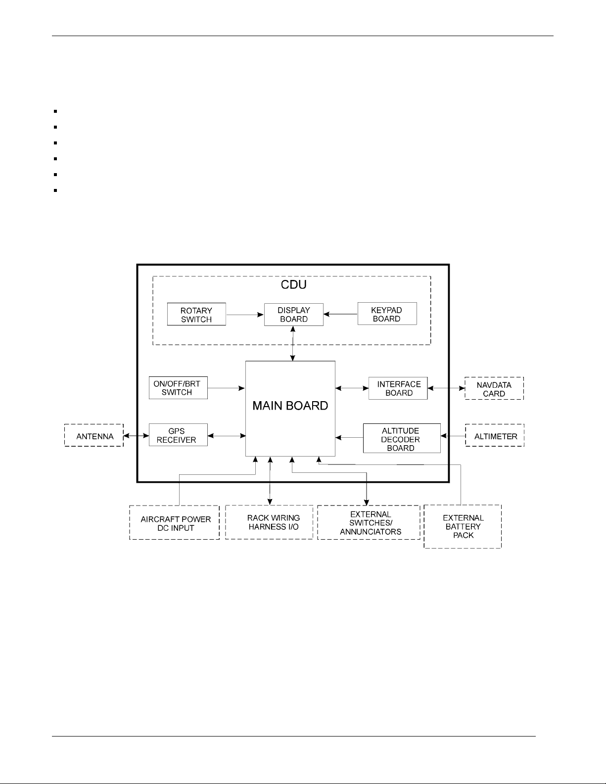
Internally, the GPS 155XL is divided into six printed circuit boards:
Main
GPS Receiver
Altitude Decoder
Interface
Display
Keypad Circuit
Figure 1-1 shows the block diagram for the GPS 155XL.
Figure 1-1. GPS 155XL Block Diagram
1-2 190-00067-25 Rev D
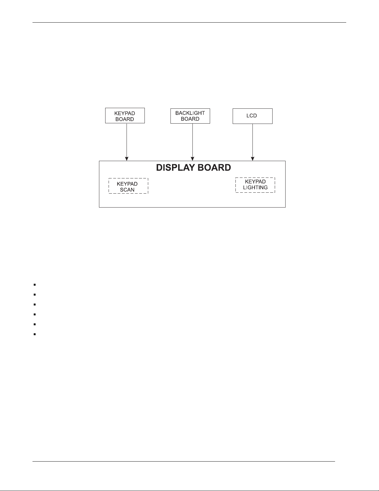
1.3.1 Control Display Uni t
The Control/Display Unit (CDU) is an assembly consisting of eleven keycaps, keypad board, optical lens, liquid
crystal display and board with heat sealed drivers, photocell and screws. All components are housed in a die cast
bezel with a dual concentric rotary switch and knobs. There are two LED’s behind each keycap, providing
backlighting for nighttime use.
Figure 1-2. GPS 155XL Control/Display Unit Block Diagram
1.3.2 Main Board Assembly
The Main Board Assembly consists of the following:
Central Processing Unit (CPU)
Operating system Read-Only Memory (ROM)
System memory
Discrete Input/Output (I/O)
Serial communication drivers and receivers
Power supply
These items are discussed in detail in the following paragraphs. Figure 1-3 shows the Main Board Assembly
block diagram.
1.3.2.1 CPU Board
The CPU Board is a microprocessor-based computer board. This board contains an Intel 80L186EB
microprocessor running at 16 MHz, a plug-in read only memory chip (ROM) and random access memory chips
(RAM). Data stored in RAM is maintained by a 3-V lithium battery when the unit is switched off and by the
regulated 5-V supply when the unit is powered on. A custom large scale integrated circuit (LSI) is used to
decode signals from the GPS satellites. A real time clock Integrated Circuit (IC) is used to keep track of the date
and time.
190-00067-25 Rev D 1-3
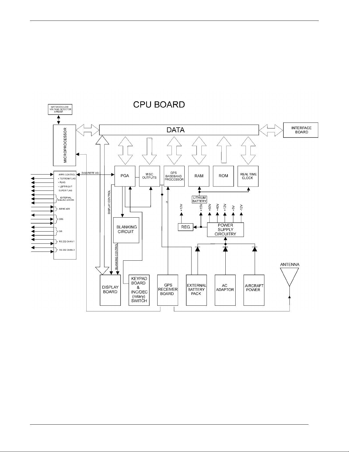
Other circuits on the Main Board are used for I/O functions such as controlling the display, reading the keypad,
and controlling the receiver. Discrete I/O lines are provided for CDI course deviation, CDI to/from flag, CDI
NAV flag, Super Flag, external annunciators, omni bearing selector (OBS) course, and to activate the Approach
mode. Serial communication lines for omni bearing indication (OBI) (clock/data/sync), ARINC 429, and RS-232
(two channels) are also included. Figure 1-3 shows the Main Board block diagram.
Figure 1-3. GPS 155XL Main Board Assembly Block Diagram
1.3.2.2 CPU Power Supply Circuits
The power supply section of the CPU board outputs +14 to +29 V for the LCD display, ± 12 V, + 15 V, and +5
V (V
). In addition, the CPU board contains comparator circuits for detecting low Ni-Cad battery level, low
CC
memory battery voltage, and external power. The external power input is through the rear connector (J1) and
from the AC adapter through a DC power jack located near the rear connector.
1-4 190-00067-25 Rev D
External battery pack power is also applied to the rear connector (J1). All of these sources are diode isolated to
prevent parallel sourcing. The unit is turned on and off by a digital latch circuit operated by a knob located on
the front panel adjacent to the data card opening. The switching circuit is a fly-back design and operates at a
frequency of approximately 128 kHz. The +15 V output is post regulated to provide 11.75 to 12.25-V. The +5 V
output is regulated at 4.8-V. All other voltages are ±20%.
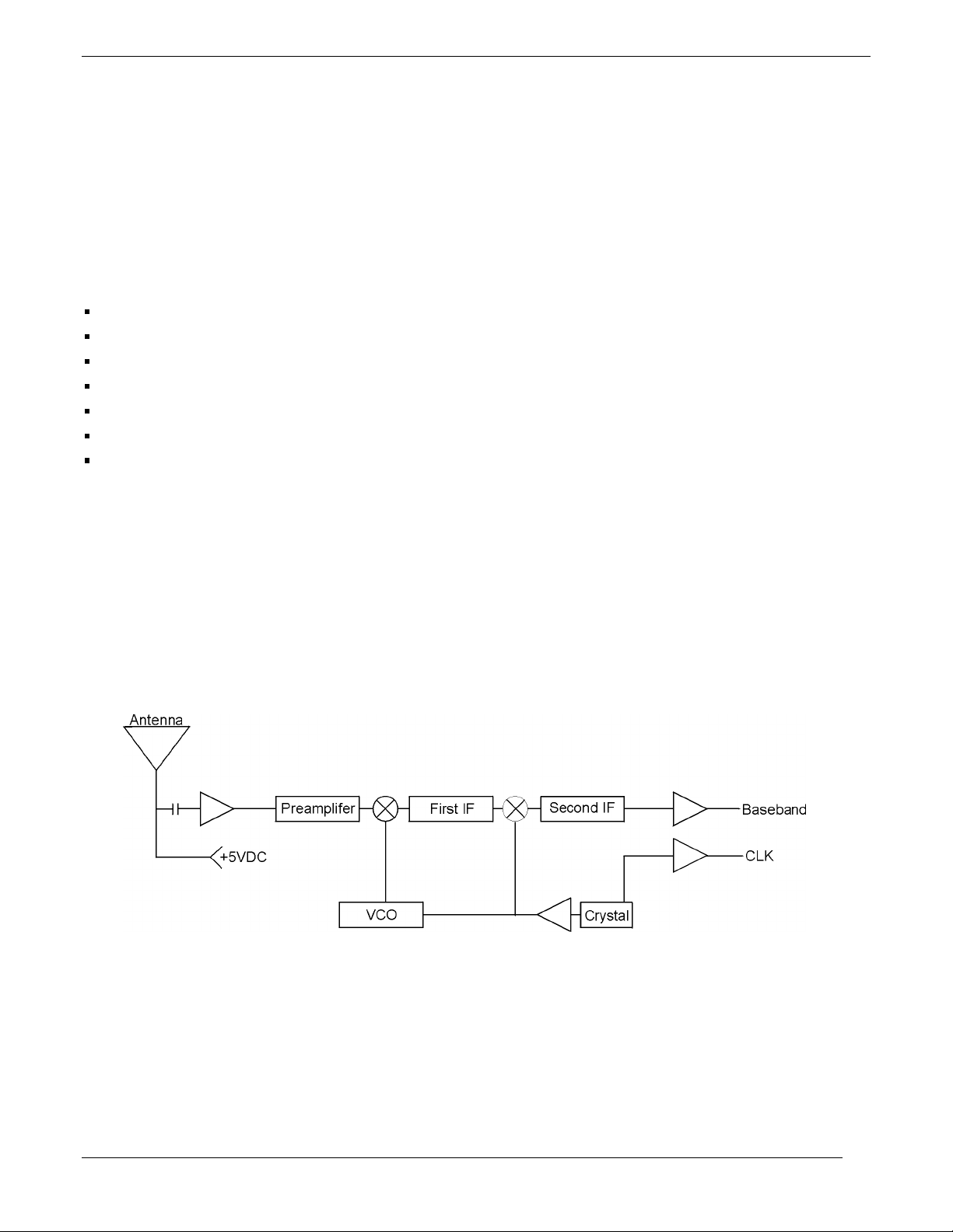
1.3.3 G PS Recei ver
The GPS Receiver (Figure 1-4) consists of the following circuitry:
Dual conversion receiver
Frequency synthesizer
High precision crystal oscillator
Ceramic RF filter
RF and IF amplifiers
Mixers
IF filter
The frequency synthesizer uses the high-precision oscillator as a reference frequency for the phase detector in the
synthesizer. The resultant frequency is used in the mixer section to product the first intermediate frequency (IF).
After further amplification and mixing with a product of the crystal oscillator, the baseband IF is passed to the
CPU Board for processing. The crystal output is also used for the system clock pulse. The GPS assembly is
contained within a shielding fence/cover and connection to the antenna is made via a BNC connector. The GPS
supplies +5 V to the antenna’s preamplifier through this BNC connector. The block diagram in Figure 1-4 shows
the interaction between components on the GPS Assembly.
Figure 1-4. GPS 155XL GPS Receiver Block Diagram
190-00067-25 Rev D 1-5

1.3.4 Int erface Board and Data Cards
When servicing the GPS 155XL, user-defined waypoints, routes, settings, etc.,
may be saved on a user data card (768 kilobytes of Flash Memory; P/N 010-
10032-03). Refer to the GPS 155XL Pilot’s Guide for additional information on
using the data card.
The Interface Board provides two-way data transfer capability between the CPU board and a Data Card. Address
and data lines from the CPU board route through the Interface Board to the data card. A plastic race secures the
Interface Board at the front of the unit and serves to guide the data card onto a 40-pin connector.
1.3.5 Altitude Decoder Board
The Altitude Decoder Board contains the 26-pin rear connector (J2), discrete/parallel inputs and
Gillham/Greycode decoder circuitry. Encoded pressure altitude data from a parallel altimeter device is received
as a 10-bit data word at the 26-pin rear connector. Diode isolation on these input lines prevents damage to the
unit. The data is then decoded and output to the Main Board. The Altitude Decoder Board also provides a
discrete input for the GPS SEQ switch. When grounded, this line activates the unit’s HOLD mode.
1-6 190-00067-25 Rev D

SECTION 2
SPECIAL TOOLS AND TEST EQUIPMENT
2.1 INTRODUCTION
This section identifies the special tools and test equipment necessary to repair the GPS 155XL. Standard
equipment is not listed. For any questions regarding special tools and test equipment, contact the GARMIN
Customer Service Department listed on Page 1-1.
2.2 SPECIAL TOOLS AND TEST EQUIPMENT
Test Harness—User Supplied
Test Panel—User Supplied
2.3 TEST PANEL/TEST HARNESS
Test Fixtures/Test Harnesses are User Supplied. Load and signal information given in Figures 2-1 and 2-2 can
aid in the fabrication of any Test Fixtures or Panels.
190-00067-25 Rev D 2-1
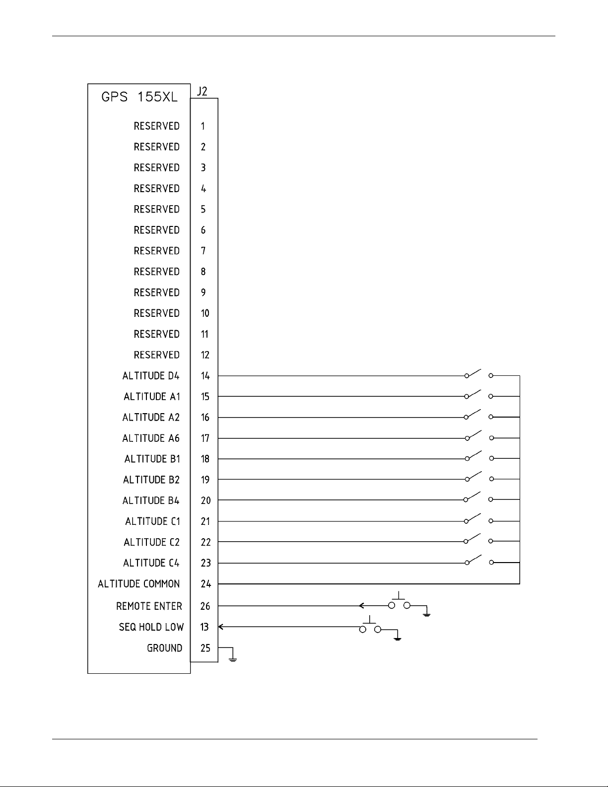
Figure 2-1. J2 Test Setup/Test Harness Diagram
2-2 190-00067-25 Rev D
SECTION 3
TROUBLESHOOTING
The GPS 155XL contains static sensitive components. Observe proper anti-static
procedures when troubleshooting the unit.
3.1 INTRODUCTION
This section contains information to aid in troubleshooting the GPS 155XL to the assembly level.
3.2 TROUBLESHOOTING EQUI PMENT
Test Fixtures/Test Harnesses are User Supplied. Load and signal information
given in Figures 2-1 and 2-2 can aid in the fabrication of any Test Fixtures or
Panels.
The following equipment (or a suitable substitute) is necessary to perform troubleshooting:
1. Power Supply Capable of 10-33 Volts @ 6 Amps
2. Digital DVM—Fluke 8000A
3. BFGoodrich Precision Track Selector
4. GPS Antenna—Garmin GA56 (P/N 010-10040-01)
5. Male to Male BNC Cable 10 ±1dB attenuation (P/N 320-00088-00)
6. Red and Black Cables with Banana Plugs (3 ft. recommended)
7. 60 MHz Oscilloscope
3.3 SELF-TEST FAILURES
The GPS 155XL monitors many of its internal functions and displays a message to alert the user if a failure
occurs. Table 3-1 shows the recommended repair for each self-test failure message. When multiple repair
actions are listed, the most probable failure is listed first.
190-00067-25 Rev D 3-1
 Loading...