

Page 1
quick
start
guide
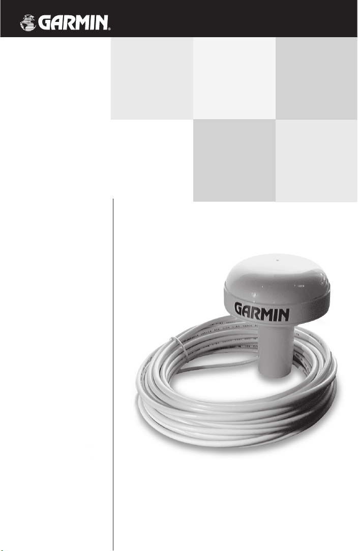
GPS 17
GPS receiver/antenna
Page 2

© 2004 Garmin Corporation
Garmin International, Inc.
1200 East 151st Street, Olathe, Kansas 66062, U.S.A.
Tel. 913/397.8200 or 800/800.1020
Fax 913/397.8282
Garmin (Europe) Ltd.
Unit 5, The Quadrangle, Abbey Park Industrial Estate, Romsey, SO51 9DL, U.K.
Tel. 44/0870.8501241
Fax 44/0870.8501251
Garmin Corporation
No. 68, Jangshu 2nd Rd., Shijr, Taipei County, Taiwan
Tel. 886/02.2642.9199
Fax 886/02.2642.9099
All rights reserved. Except as expressly provided herein, no part of this manual may
be reproduced, copied, transmitted, disseminated, downloaded or stored in any
storage medium, for any purpose without prior written consent of Garmin Corporation. Garmin Corporation hereby grants permission to download a single copy of
this manual onto a hard drive or other electronic storage medium to be viewed for
personal use, provided that such electronic or printed copy of this manual contains
the complete text of this copyright notice and provided further that any unauthorized commercial distribution of this manual is strictly prohibited.
Information in this manual is subject to change without notice. Garmin
Corporation reserves the right to change or improve its products and to make
changes in the content without obligation to notify any person or organization of
such changes. Visit the Garmin web site (www.garmin.com) for current updates
and supplemental information concerning the use and operation of this and other
Garmin products.
Garmin® and AutoLocate® are registered trademarks of Garmin Corporation and
may not be used without the express permission of Garmin Corporation.
October 2004 Part Number 190-00228-10 Rev. C Printed in Taiwan
Page 3
1
Introduction
Limited Warranty
Garmin Corporation warrants this product to be free
from defects in materials and workmanship for one year from
the date of purchase. Garmin will, at its sole option, repair or
replace any components that fail in normal use. Such repairs
or replacement will be made at no charge to the customer for
parts or labor. The customer is, however, responsible for any
transportation costs. This warranty does not cover failures
due to abuse, misuse, accident, or unauthorized alteration or
repairs.
THE WARRANTIES AND REMEDIES CONTAINED
HEREIN ARE EXCLUSIVE AND IN LIEU OF ALL OTHER
WARRANTIES EXPRESS OR IMPLIED OR STATUTORY,
INCLUDING ANY LIABILITY ARISING UNDER ANY WARRANTY OF MERCHANTABILITY OR FITNESS FOR A
PARTICULAR PURPOSE, STATUTORY OR OTHERWISE.
THIS WARRANTY GIVES YOU SPECIFIC LEGAL RIGHTS,
WHICH MAY VARY FROM STATE TO STATE.
IN NO EVENT SHALL Garmin BE LIABLE FOR ANY
INCIDENTAL, SPECIAL, INDIRECT OR CONSEQUENTIAL DAMAGES, WHETHER RESULTING FROM THE
USE, MISUSE, OR INABILITY TO USE THIS PRODUCT
OR FROM DEFECTS IN THE PRODUCT. SOME STATES
DO NOT ALLOW THE EXCLUSION OF INCIDENTAL OR
CONSEQUENTIAL DAMAGES, SO THE ABOVE
LIMITATIONS MAY NOT APPLY TO YOU.
To obtain warranty service, contact your Garmin dealer
or call the Garmin’s Produce Support department (913-397-
8200) for a returned merchandise tracking number. The
unit should be securely packaged with the tracking number
clearly marked on the outside of the package and sent
freight prepaid and insured to a Garmin warranty service
station. A copy of the original sales receipt is required as the
proof of purchase for warranty repairs. Garmin retains the
exclusive right to repair or replace the unit or software or
offer a full refund of the purchase price at its sole discretion.
SUCH REMEDY SHALL BE YOUR SOLE AND EXCLUSIVE
REMEDY FOR ANY BREACH OF WARRANTY.
The Garmin GPS 17 has no
user-serviceable parts. Should
you ever encounter a problem
with your receiver, please
contact your Garmin dealer or
the Garmin’s Product Support
department (913-397-8200 or
800-800-1020) for repairs.
Any attempt to open the case
to change or modify the unit
in any way will void your warranty and may result in per
-
manent damage to the equipment.
Serial Number
Use this area to record the
serial number (8-digit number
located on the bottom of the
antenna) in case it is lost,
stolen, or needs service. Be
sure to keep your original sales
receipt in a safe place or attach
a photocopy inside the manual.
Serial Number:
I
Page 4

2
Introduction
Cautions
The GPS system is operated by the government of the
United States which is solely responsible for their accuracy
and maintenance. The Global Positioning System and the
Differential Global Positioning System are under development and are subject to changes which could affect accuracy
and performance of all GPS equipment. Although a GPS
system is a precision electronic NAVigation AID (NAVAID),
any NAVAID can be misused or misinterpreted, and therefore
become unsafe. Use the GPS system at your own risk. To
reduce this risk, carefully review and understand all aspects
of this Quick Start Guide and carefully compare indications
from your display to all available navigation sources including the information from other NAVAIDs, visual sightings,
charts, etc. For safety, always resolve any discrepancies before
continuing navigation.
NOTE: This device complies with Part 15 of the FCC
rules. Operation of this device is subject to the following
conditions: (1) This device may not cause harmful interference, and (2) this device must accept any interference
received, including interference that may cause undesired
operation.
Page 5

3
Introduction
Table of
Contents
Introduction
Limited Warranty................................................1
Cautions ............................................................2
Table of Contents ...............................................3
Overview
Capabilities & Package Contents........................4
Specifications..................................................5
Installation
Mounting the GPS 17..............................6-8
Wiring the GPS 17......................................9-10
Operation
Using the GPS 17 ................................11-12
Page 6

4
Introduction
Capabilities
The GPS 17 offers a host of powerful capabilities for
enhanced performance and accuracy:
• Performance— WAAS enabled, 12-channel GPS
receiver tracks and uses up to 12 satellites for fast,
accurate positioning.
• Ease of Use—
Once installed, unit will automatically
transmit navigation data.
• Convenience— May be remotely mounted in an outof-the-way location. Receiver status information is displayed directly on the chartplotter or PC.
• Low Power Consumption— Draws approximately
65 milliamps during normal operation.
• GPS Accuracy
Position: < 15 meters, 95% (typical)*
Velocity: .1 knot RMS steady state
• DGPS (USCG) Accuracy
Position: 3-5 meters, 95% (typical)
Velocity: .1 knot RMS steady state
• DGPS (WAAS) Accuracy
Position: < 3 meters, 95% (typical)
Velocity: .1 knot RMS steady state
Package Contents
Your Garmin GPS 17 package includes:
• GPS 17 unit
• 30’ Power/Data Cable
• Quick Start Guide
If any parts are missing or damaged, please contact
your Garmin dealer immediately.
* Subject to accuracy degradation to 100m 2DRMS under the U.S.
Department of Defense imposed Selective Availability Program.
Capabilities &
Package Contents
Page 7

5
Overview
Physical
Size: 3.58”D x 4.25”H
(91mm x 108mm)
Weight: 1.0 pound (0.373 kg)
Operating Range: -40°F to +176°F
(-40°C to +80°C)
Waterproof: -1 meter submersion for 30 minutes
IPX7 rating for IEC529
Mount Thread Size: 1” diameter at 14 threads/inch
Cable: Foil-shielded 8 conductor 28 AWG
GPS 17- RJ-45 Connector
GPS 17- Bare wire leads
Dynamics: 999 knots, 6g’s
Power
Voltage: 8 - 40 Vdc unregulated
Current Drain: 65 mA @ 12 Vdc
28 mA @ 40 Vdc
Sensitivity: -165 dBW minimum
Interfaces
Serial Port 1: Selectable between NMEA and Garmin.
NMEA 0183 v2.0 (ASCII), GPALM,
GPGGA, GPGLL, GPGSA, GPGSV,
GPRMC, GPVTG, PGRME, PGRMF,
PGRMT and PGRMV output.
Serial Port 2: RTCM Input Only. RTCM SC-104 differ
ential input message types 1, 2, 3, 7
and 9
Baud Rates: 300 -19200
GPS 17
Specifications
Complete information concerning NMEA & RTCM formats
and sentences is available for
purchase at:
National Marine Electronics
Association (NMEA)
PO Box 3435
New Bern, NC 28564-3435
USA
252-638-2626
252-638-4885 FAX.
www.nmea.org
Radio Technical Commission
For Maritime Services (RTCM)
1800 Diagonal Road, Suite
600
Alexandria, VA 22314-2480,
USA
703-684-4481 (Info Only)
703-836-4229 FAX
www.rtcm.org
F
Page 8
6
Mounting the Receiver
Please read through these instructions thoroughly before
attempting installation. Make sure you completely understand
these instructions before you begin. When in doubt, seek professional assistance.
The following additional items are needed or optional to
complete the installation of your GPS 17:
• Antenna mount— Since antenna mounting locations
and methods vary, you will need to obtain an antenna mount
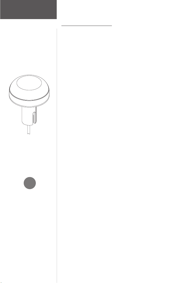
to install the GPS 17. The receiver base fits a standard 1inch, 14 threads-per-inch marine mount. Check with your
Garmin dealer or a marine supply retailer for this item.
• On/Off switch (optional)— Power to the receiver
may be controlled by an on/off switch, such as an accessory
switch on the control console. Check with your Garmin
dealer or a marine/electric supply retailer for this item.
It is recommended that the system be temporarily
hooked up with the wiring and the unit placed at the desired
installation location. Then, check operation with potential
interfering equipment turned on and off. (For example, other
electronic equipment, fan motors, engine ignition, alternators, generators, radars, and VHF radio transmissions can be
sources of interference.)
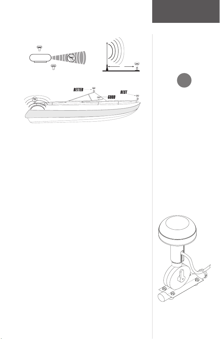
Position the receiver so that the clearest possible view
of the sky and horizon in all directions is obtained. Avoid
mounting the antenna next to large areas of conductive
material (metal, aluminum, etc.) as this may cause poor
signal reception. It is not recommended that the GPS 17 be
mounted high on a mast, as the top of the mast travels more
than the boat. The unit will provide more stable readings if
it is located nearer to the water level. The GPS 17 is supplied
with a 30 feet power/data cable. When routing the wiring to
the GPS 17, avoid routing the cable near the vessel’s alternator or ignition system components or parallel to other power
lines.
Installation
Mounting the
GPS 17
Note: As a general rule, mount
the receiver at least three
feet from all other antennas
and the vessel’s electrical
system components
(alternator/ignition system).
I
Page 9
7
Installation
If a problem is found, try altering the location of the unit
or wiring. Often moving the antenna a few feet away from the
source of interference will solve the problem. When a suitable
configuration is found, a permanent installation should be
made. Select the mounting location according to your preferences. Keep in mind that from this mounting location cables
will be routed to the NMEA listening device.
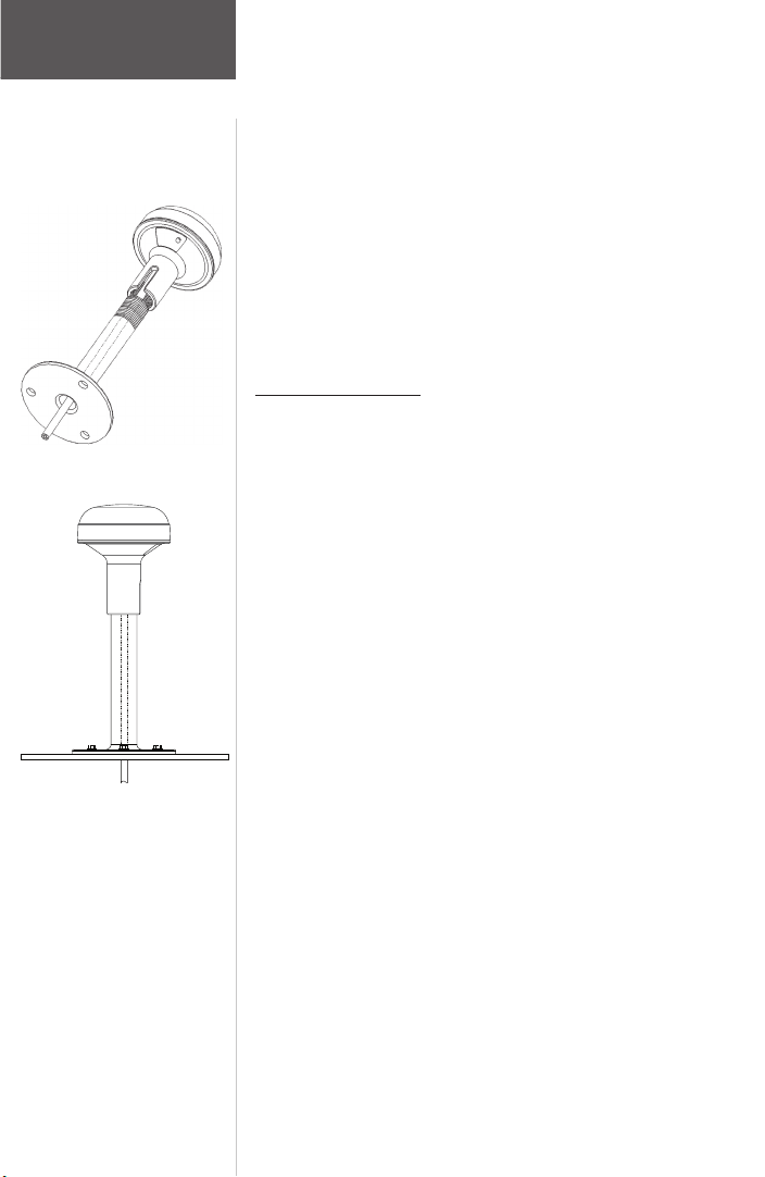
Mounting the GPS 17 with cable outside mount:
1. Place the cable in the vertical slot along the side of the
base of the unit.
2. Screw the GPS 17 onto the mount. Make sure that you
do not overtighten the head. It is possible to tighten the
unit to the point that the cable may be cut in two.
3. With the GPS 17 and mount installed, fill the remaining
gap in the cable exit on the with a marine sealant.
4. Route the power/data cable from the GPS 17 to the
desired device. Excess cable may be shortened or coiled
together and secured in an inconspicuous location.
Three common sources of interference for GPS units are:
Radar
ABOVE- O
K
BELOW- O
K
EMI
SS JA
YHA
WK
3'
VHF Radio Antenna
Radar
EMI (Electromagnetic Interference) from engine components
When routing the power/data
cable, try to avoid:
• Sharp edges which may cut
the cable.
• Routing the cable parallel to
other power lines.
• Excessively twisting, straining
or bending the cable.
Mounting the
GPS 17
I
Page 10
8
Installation
Mounting the
GPS 17
Wiring the GPS 17
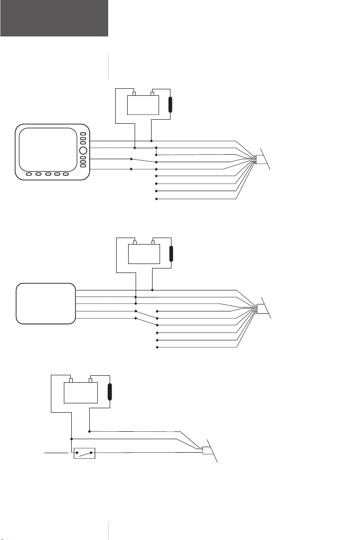
The final step in installing the GPS 17 is to connect the
receiver’s Port 1 DATA IN, DATA OUT, REMOTE ON/OFF,
and GROUND (Return) lines to your NMEA device or PC.
Port 2 is used for RTCM input only. The GPS 17 may be
plugged directly into a RJ-45 receptacle, which accepts
NMEA data. It is recommended that a 1A fuse be installed
on the power (+) line of the receiving RJ-45 receptacle or
equivalent device. Color coding of the wires is the same on
both the GPS 17 and GPS 17 (see wiring diagrams on following pages). If necessary, the wire coloring on the GPS 17 may
be seen through the clear RJ-45 connector.
For reliable communication, it is essential that the GPS
17 and the receiving device share the same ground. This
ground connection acts as the (signal) Return line. It is
recommended to wire the unit to its own circuit to avoid
interference from other electronics.
Mounting the GPS 17 with cable through mount:
1. Position the mount in the desire location and mark the
approximate center of the mount
2. Drill a hole large enough for the cable (or RJ-45 con
-
nector) to pass through at the marked location.
3. Slide the cable through the mount and screw the GPS
17 onto the mount.
4. Fasten the mount to the boat
5. When running the cable, attempt to keep the cable
away from sources of electronic interference.
Wire Coloring:
RED- Power (+) 8-40 Vdc
BLACK- Ground (Power (-) and Data Signal Return)
YELLOW- Remote power On/Off
BLUE- Port 1 NMEA Data Input
WHITE- Port 1 NMEA Data Output
GREEN- Port 2 RTCM Data Input
VIOLET- Port 2 RTCM Data Output
(Reserved for Future Use)
GRAY- Pulse Per Second Output
(See Technical Specifications)
Page 11
9
Installation
Wiring
the GPS 17
I
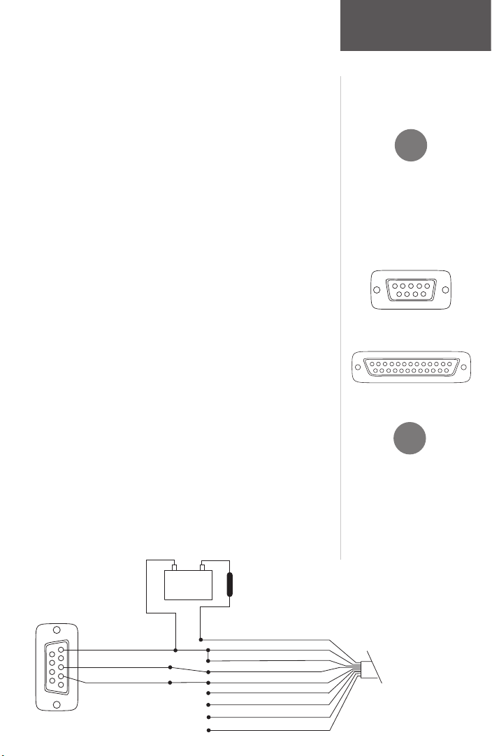
If the GPS 17 is being connected to a PC, a DB9 or
DB25 serial connector (normally female) will be needed.
Check with a PC or electronics
supplier for this item.
Some non-Garmin devices
may have a separate data line
labeled “RETURN”, “DATA
GROUND” or “DATA -”. If
one of these lines exist, connect
the BLACK wire from the
power/data cable to it.
14
7
25
13
123
F
DB9 Female Serial Connector
DB25 Female Serial Connector
1
4
6789
2
3
5
Wiring the GPS 17 to a NMEA Device or PC Connector:
1. You may reference the following diagrams for the
wiring: Connect the WHITE (Port 1 Data Out) wire from
the GPS 17’s power/data cable to the DATA INPUT line
of the NMEA device or to pin 2 on a DB9 (pin 3 on
DB25). You may output data to no more than three
NMEA devices.
2. Connect the BLUE (Port 1 Data In) wire to the DATA
OUTPUT line of the NMEA device or pin 3 on the DB9
(pin 2 on DB25).
3. Connect the BLACK (-) wire to the GROUND wire of the
NMEA device and/or pin 5 on the DB9 (pin 7 on DB25).
If connecting to a PC, the BLACK (-) wire must also
be run to a ground. If the BLACK wire is connected
to the same ground terminal as the NMEA device,
no additional connection is required, unless a separate
data return line is required by the NMEA device).
4. Connect the RED (+) wire from the power/data cable to
a 8-40 Vdc power source.
5. If a remote power switch is being installed, reference
the following page for wiring a switch. This will allow
the GPS 17 to remain connected to a power source,
but manually powered on (pull down to less than 0.5
volts) and off (open). Otherwise, if the receiver is being
wired to a circuit which is already switched, (with the
NMEA device for example) connect the YELLOW wire
to the same place as the BLACK wire. When the BLACK
and YELLOW wires are combined, the GPS 17 will turn
on/off when power is applied/removed to the RED (+)
wire.
GPS 17
Power/Data Cable &
D B-9 Serial Co nnection
GPS 17
PIN 5: GROUN D
PIN
3: D ATA OU T
PIN 2: D ATA IN
1
4
6
7
8
9
Power/Data Cabl
e
Power Source
(-)
(+)
D B-9
Serial Co nnector
Fuse
1A
VIOLET: POR T 2 D ATA OU T (n/c)
G R EEN : POR T 2 DATA IN (n/c)
YELLO W : RE M O TE ON /OFF
BLAC K: GROUN
D
BLU E
: POR T 1 DATA IN
W H
ITE : POR T 1 DATA OU T
G R AY: PPS
(n/c)
RE D : 6-40 VDC
BAR E W IRE: D R AIN (n/c)
Page 12
10
Installation
Wiring
the GPS 17
GPS 17
NMEA Device Connection
GPS 17
VIOLET: PORT 2 DATA OUT (n/c)
G REEN : PORT 2 DA TA IN (n/c)
YELLO W :
R EM OT E ON /OFF
BLAC K: GROU ND
BLUE
: PORT 1 DATA IN
G ROU ND
W HITE: PORT 1 DA TA
OUT
DA TA
OUT
DA TA IN
Pow er/D ata C able
Power Source
(-)
(+)
NMEA Device
Fuse
1A
Pow er/D ata C able &
G RA Y: PPS (n/c)
RED : 6-40 V DC
PO W E
R
BAR E W IRE: D R AIN (n/c)
GPS 17
NMEA Device Connection
GPS 17
VIOLET: PORT 2 DATA OUT (n/c)
G REEN
: PORT 2 DA TA IN
YELLO W :
R EM OT E ON /OFF
BLAC K: GROU ND
BLUE : PORT 1 DA TA IN (n/c)
W HITE: PORT 1 DA TA OUT
Pow er/D ata C able
(-)
(+)
Fuse
1A
Pow er/D ata C able &
G RA Y: PPS (n/c)
RED :
6-40 VDC
G A R M IN D GPS
G B R 21/23
W HITE: R EM OT E O N /OFF
BLAC K: GROU ND
BRO W N:
DA T A IN
BLUE
: DA TA OUT
RED :
6-40 VDC
(Rem ote Pow er 23 O nly)
Power Source
BAR E W IRE: D R AIN (n/c)
GPS 17
6-40 VDC
(5) YELLOW : REMOTE ON/OFF*
(1) RE D :
6-40 VDC
(2) BLAC K: GRO UN D
Switch
Pow e
r/D ata C able
R em o
te Pow er Switch
Closed- ON
O pen- OFF
(-) (+)
GPS 17
Pow er/D ata C abl
e
Fuse
1A
Page 13

11
First Time Fix
The first time you power up your new GPS 17, the
receiver must be given an opportunity to collect satellite data
and establish its present position. To ensure proper initialization, the GPS 17 is shipped from the factory in AutoLocate
mode, which will allow the receiver to “find itself” anywhere
in the world.
Once the GPS17 is installed and powered on, it will
begin to search for satellites.The GPS 17 will output naviga
tion data once it has calculated an initial position fix. By
default, the following data will be output in NMEA 0183,
Version 2.0 format:
• Latitude/Longitude/Altitude (GPGGA, GPRMC)
• Velocity (GPRMC)
• Date/Time (GPRMC)
• Error Estimates (PGRME)
• Satellite and Receiver Status (GPGSA, GPGSV,
PGRMB, PGRMT)
WAAS Capability
The GPS 17 is capable of receiving WAAS (Wide Area
Augmentation System) satellite signals. WAAS is an FAA
(Federal Aviation Administration) funded project to improve
the overall accuracy and integrity of the GPS signal for aviation use, but land/sea based users may also benefit from this
system. At this time, the system is still in the development
stage and is not fully operational.
There are currently two WAAS satellites that can be
received in the U.S.A., one over the Atlantic Ocean and
one over the Pacific Ocean, in a geo-stationary orbit over the
equator. Effective use of the WAAS satellite signal may be
limited by your geographic location in relation to those satel
lites, now in developmental service. WAAS satellite signal
reception requires an absolute clear view of the sky and
works best when there are no nearby obstructions such as
buildings, mountains, etc. WAAS satellites will be numbered
33 or higher on the sky view on your NMEA device.
Operation
Using the
GPS 17
Page 14

12
Operation
Using the
GPS 17
Initial reception of the WAAS signal may take up to
15-20 minutes, then 1-2 minutes afterwards. When the GPS
satellites are receiving WAAS differential correction, a ‘D’ will
appear in the signal bar of the sky view and ‘2D or 3D Differential’ will appear in the receiver status. To learn more about
the WAAS system, its satellite positions and current state of
development, visit the FAA web site (http://gps.faa.gov).
Interfaces
The GPS 17 serial Port 1 interface protocol design is
based on the National Marine Electronics Association’s
(NMEA) 0183 ASCII interface specification, which is fully
defined in “NMEA 0183, Version 2.0” and the Radio Technical Commission for Maritime Services “RTCM Recommended
Standards For Differential Navstar GPS Service, Version 2.1,
RTCM Special Committee No. 104”. Contact information to
obtain copies of the NMEA and RTCM specifications may be
found on page 5.
Port 2 is designated for RTCM data input only. Output
on Port 2 is reserved for future use.
The GPS 17 interface protocol also transmits additional
information using the convention of Garmin proprietary
sentences ($PGxxx). Complete information on GPS 17 capabilities, data transfer, NMEA sentence formats and descriptions can be found in the “GPS 17 Technical Specifications”
(190-00228-20). You may order a copy of these specifications from Garmin or your Garmin dealer, or you may also
download a copy from the manuals section of the Garmin
web site at www.garmin.com/support/userManual.html.
The GPS 17 Port 1 is capable of transmitting the following NMEA data sentences:
GPALM, GPGGA, GPGSA, GPGSV, GPRMC, GPVTG,
GPGLL, PGRME, PGRMF, PGRMT, PGRMV, and PGRMB
The GPS 17 Port 1 is capable of receiving the following
NMEA data sentences:
GPALM, PGRMI, PGRMC, PGRMC1, PGRMO, and PSLIB.
The following NMEA transmitted sentences are enabled at
the factory: GPGGA, GPGSA,
GPGSV, GPRMC, PGRMB,
PGRME, PGRMT, and PSLIB
F
Page 15

Page 16

© 2004 GARMIN Corporation
GARMIN International, Inc.
1200 East 151st Street, Olathe, Kansas 66062, U.S.A.
GARMIN (Europe) Ltd.
Unit 5, The Quadrangle, Abbey Park Industrial Estate, Romsey, SO51 9DL, U.K.
GARMIN Corporation
No. 68, Jangshu 2nd Rd., Shijr, Taipei County, Taiwan
www.garmin.com
Part Number 190-00228-10 Rev. C
 Loading...