

Page 1

Pub. 42004-669L2E
GAI-TRONICS® CORPORATION
A HUBBELL COMPANY
SSM110 Card Rack Assembly Installation,
Operation, Mai ntenance Manual
TABLE OF C ONTENTS
Confidentiality Notice.................................................................................................................1
System Overview.........................................................................................................................1
System Design Considerations ...................................................................................................2
Capacities/Limitations.......................................................................................................................2
Station and Access Panel Power........................................................................................................2
Installation.................................................................................................................................3
Installing the Card Rack................................................................................................................... 3
Attaching Field Wiring......................................................................................................................4
Installing Plug-in PC Boards.............................................................................................................6
Power .................................................................................................................................................6
Installing SmartSeries Amplifiers..................................................................................................... 7
Setting the Amplifier Address........................................................................................................................7
Operation .................................................................................................................................10
Page Line Priorities......................................................................................................................... 10
Access Panel Operator..................................................................................................................... 10
Paging......................................................................................................................................................... 10
Lamp Te s t Featu re....................................................................................................................................... 10
Field Station User............................................................................................................................ 11
Page Line and Party Line Operation............................................................................................................. 11
Optional Ancillary Equipment.................................................................................................12
Audio Messenger Interface..............................................................................................................12
Building Entrance Protection Barrier.............................................................................................12
System Status and Status Reporting......................................................................................... 13
Status Messages............................................................................................................................... 13
Display History Buffer.....................................................................................................................13
Access Panel Display........................................................................................................................14
System Printer.................................................................................................................................14
Contents of a Status Message.......................................................................................................... 14
Device Fault Messages................................................................................................................................. 15
Device Restore Messages ........................................................................................................ ..................... 15
Page Messages............................................................................................................................................. 15
GAI-Tronics Corporation P.O. Box 1060, Reading, PA 19607-1060 USA
610-777-1374 800-492-1212 Fax: 610-796-5954
ISIT WWW.GAI-TRONICS.COM FOR PRODUCT LITERATURE AND MANUALS
V
Page 2

Table of Contents Pub. 42004-669L2E
System Startup and Shutdown..................................................................................................16
Cold Starting the System.................................................................................................................16
Warm Starting the System.............................................................................................................. 16
System Shutdown.............................................................................................................................16
The Programming Process.......................................................................................................17
ADVANCE System Files ................................................................................................................. 18
The .hot File................................................................................................................................................ 18
The .cfg File................................................................................................................................................ 18
Process Flow ....................................................................................................................................19
Maintenance.............................................................................................................................20
General Information........................................................................................................................20
Troubleshooting Guide.................................................................................................................... 20
System Hum or Buzz................................................................................................................................... 20
Static Charges.............................................................................................................................................. 20
Audio Voltage..............................................................................................................................................20
Troubleshooting the Card Rack.................................................................................................................... 21
Master Control Unit (MCU) Status Indicators............................................................................................... 21
Troubles hooting t he MC U............................................................................................................................22
Access Panel Interface (API) Card Status Indicators..................................................................................... 22
Troubles hooting t he AP I C ard...................................................................................................................... 22
Page/Party® Interface Card (PPI) Status Indicators........................................................................................ 24
Troubleshooting the PPI Card.......................................................................................................................24
Access Panel with Display........................................................................................................................... 25
Recommended Spare Parts........................................................................................................................... 26
Reference Material...................................................................................................................26
Specifications...........................................................................................................................26
Electrical..................................................................................................................................................... 26
Environmental............................................................................................................................................. 26
Mechanical.................................................................................................................................................. 26
GAI-Tronics Corporation P.O. Box 1060, Reading, PA 19607-1060 USA
610-777-1374 800-492-1212 Fax: 610-796-5954
ISIT WWW.GAI-TRONICS.COM FOR PRODUCT LITERATURE AND MANUALS
V
Page 3
Pub. 42004-669L2E
GAI-TRONICS® CORPORATION
A HUBBELL COMPANY
SSM110 Card Rack Assembly Installation,
Operation, Mai ntenance Manual
Confidentiality Notice
This manual is p rovided s olely as an operationa l, insta l lation, and ma int e nance gui de and c ontains sens itiv e
business and technical information that is confidential and proprietary to GAI-Tronics. GAI-Tronics
retains all intellectual property and other rights in or to the information contained herein, and such
information may only be used in connection with the operation of your GAI-Tronics product or system.
This manual may not be dis closed i n any f orm, in who le or in part, directly or indirectly, to a ny third part y.
System Ov erview
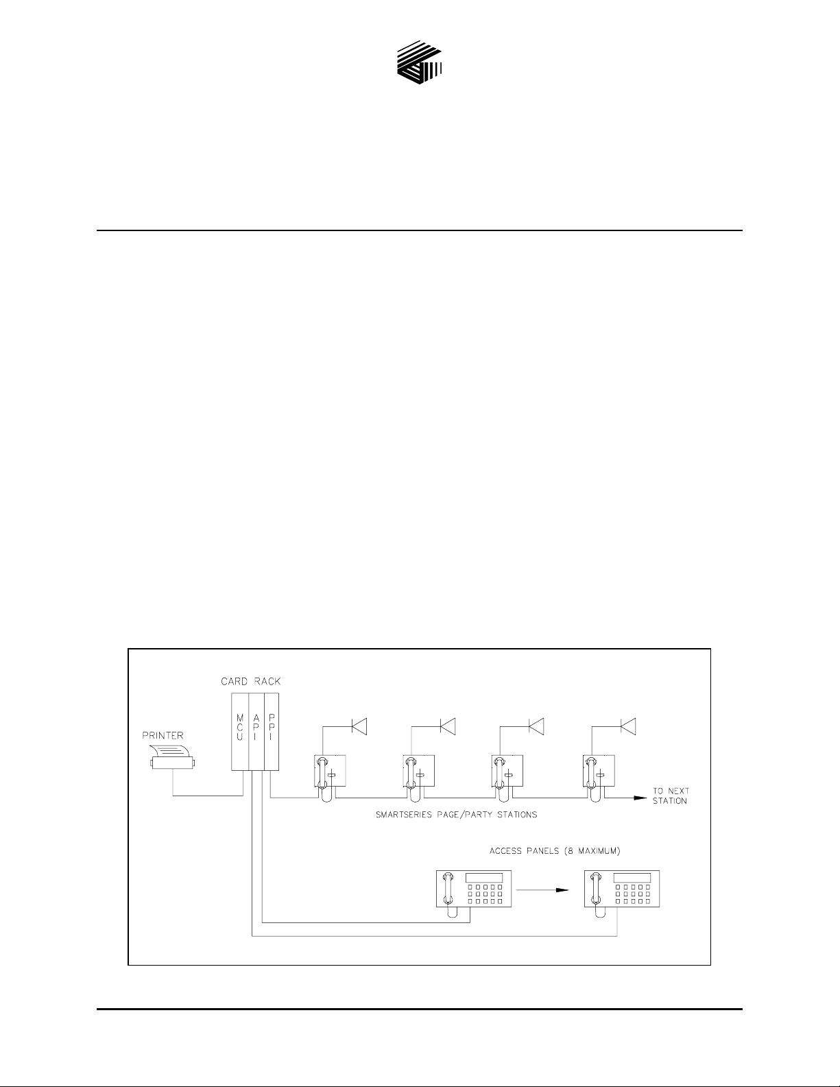
The SSM110 Card Rack Assembly is the central control device of a SmartSeries system. The SSM110
Card Rack is designed to control a single-zone SmartSeries system and up to eight access panels. This
system configuration provides health checking (supervision) for the system’s page line and party line 1
cable, handset/speaker amplifiers, and speakers and access panels. Should a fault be detected, the event
may be displayed on the access panel and a printer prints a record of the event.
SmartSeries handset stations and access panels allow personnel to page individuals throughout the
system. Additionally, two-way (telephone type) conversation can occur between stations on a party line.
Single party line systems and five party line systems are available. Refer to Figure 1 for typical system
diagram.
Figure 1. Typical System Diagram
GAI-Tronics Corporation P.O. Box 1060, Reading, PA 19607-1060 USA
610-777-1374 800-492-1212 Fax: 610-796-5954
ISIT WWW.GAI-TRONICS.COM FOR PRODUCT LITERATURE AND MANUALS
V
Page 4

Pub. 42004-669L2E
SSM110 Card Rack Assembly Installation, Oper ation, Maintenance Manual Page: 2 of 26
System Design Considera tions
Carefully plan the system layout before installation. Install handset stations in locations that allow for
convenience, accessibility, and personnel safety. For comprehensive speaker sound coverage, consider
the quantity and location of the loudspeakers—particularly in areas of high ambient noise or
reverberation.
Also, careful ly plan th e layout to mini mize the am ou nt of c abl e requ ired for ea ch ins tallati on. This is
especially important because all SmartSeries stations are wired in a branch configuration. GAI-Tronics
can supply multi-conductor cable designed specifically for this system. GAI-Tronics standard cable has
600 V insulation and is Underwriters Laboratory (UL) rated for power cable tray use.
If you need assistance in speaker layout, refer to GAI-Tronics Speaker/Horn Installation Manual
(Pub. 42004-135) for layout and speaker placement information.
Capacities/Limi tations
SmartSerie s Sta t ions—A maximum of 200 SmartSeries stations may be connected to the PPI card in the
SSM110 Card Rack.
Access Pane ls— A maximum of eight access panels may be connect ed to th e API card of the SSM1 1 0
Card Rack.
Speakers—O nly one speaker can be connected to a SmartSeries station if the station is supervising the
speaker. If speaker supervision is not being used, up to four speakers can be connected to a single station
in low noise areas. We recommend a maximum of two speakers be connected to a single station in high
noise areas.
Access Pane l Cabl e— The recommended maximum cable distance from the card rack to an access panel
is 6,560 feet (2000 meters).
GAI-Tronics System Cable—The recommended maximum cable distance from the card rack to a
SmartSeries station is 5,250 feet (1600 meters).
GAI-Tronics S peaker Cable—The recommended maximum cable distance from a SmartSeries station
to an 8-ohm speaker is 75 feet (22.86 meters). The maximum cable distance from a SmartSeries station to
a 16-ohm speaker is 150 feet (45.72 meters).
Station and A ccess Panel P ower
SmartSeries stations require 120 V ac power. GAI-Tronics system cable contains a No. 14 AWG wire
triplet for distributing ac power to the SmartSeries stations. This wire can carry a maximum of 15 amps.
Each station requires approximately 0.5 amps maximum; therefore, up to 30 SmartSeries stations can be
connected to a single power circuit. Additional stations must be powered by additional power circuits.
Access panels are supplied with a modular ac power cord. Plug one end of the cord into the mating
receptacle on the rear of the access panel the other end into a standard 15A power receptacle.
\\s_eng\gtc proddoc s \st andard iom s - current release\42004 instr. m anuals \ 42004-669l2e. doc
07/07
Page 5
Pub. 42004-669L2E
SSM110 Card Rack Assembly Installation, Oper ation, Maintenance Manual Page: 3 of 26
Installation
Installing the C ard Rack
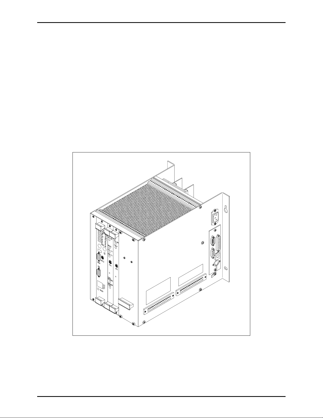
The SSM110 Card Rack is designed for wall or surface mounting. Refer to Figure 2 for the card rack
outline. Consider the following when deciding on a mounting location:
1. Is adequate space to the right side of the card rack for access to the terminal blocks, ac power cable
and printer ca b l e co nnections pr ovi ded ?
2. Can the mounting surface support the weight of the field cable when it is connected to the card rack?
3. Is a 120 V ac power receptacle located within 6 feet of the card rack? A modular line cord is supplied
with the card rack.
4. If connecting a printer, make sure there is a suitable location to install the printer so that the printer
ca ble will eas il y reach the car d rack.
Figure 2. Card Rack Outline
To mount the card rack, secure the card rack to the mounting surface using the four slotted mounting
holes on the rear flanges. Use 0.25-inch diameter screws or bolts to support the weight of the card rack,
which is approximately 10 pounds when the plug-in cards are installed.
\\s_eng\gtc proddoc s \st andard iom s - current release\42004 instr. m anuals \ 42004-669l2e. doc
07/07
Page 6

Pub. 42004-669L2E
SSM110 Card Rack Assembly Installation, Oper ation, Maintenance Manual Page: 4 of 26
Attaching Fiel d Wiring
A 16-terminal plug is provided on the side of the card rack for connecting the GAI-Tronics standard
Page/Party
®
system cable. Remove the plug from the mating receptacle to make cable termination easier.
The locking screws at either end of the plug may need to be unscrewed to remove the plug.
The conductors of the GAI-Tronics standard system cable are terminated as outlined in the following
table. The receptacle on the card rack is labeled to indicate the function of each terminal.
Figure 3. Term inal Detail
\\s_eng\gtc proddoc s \st andard iom s - current release\42004 instr. m anuals \ 42004-669l2e. doc
07/07
Page 7
Pub. 42004-669L2E
SSM110 Card Rack Assembly Installation, Oper ation, Maintenance Manual Page: 5 of 26
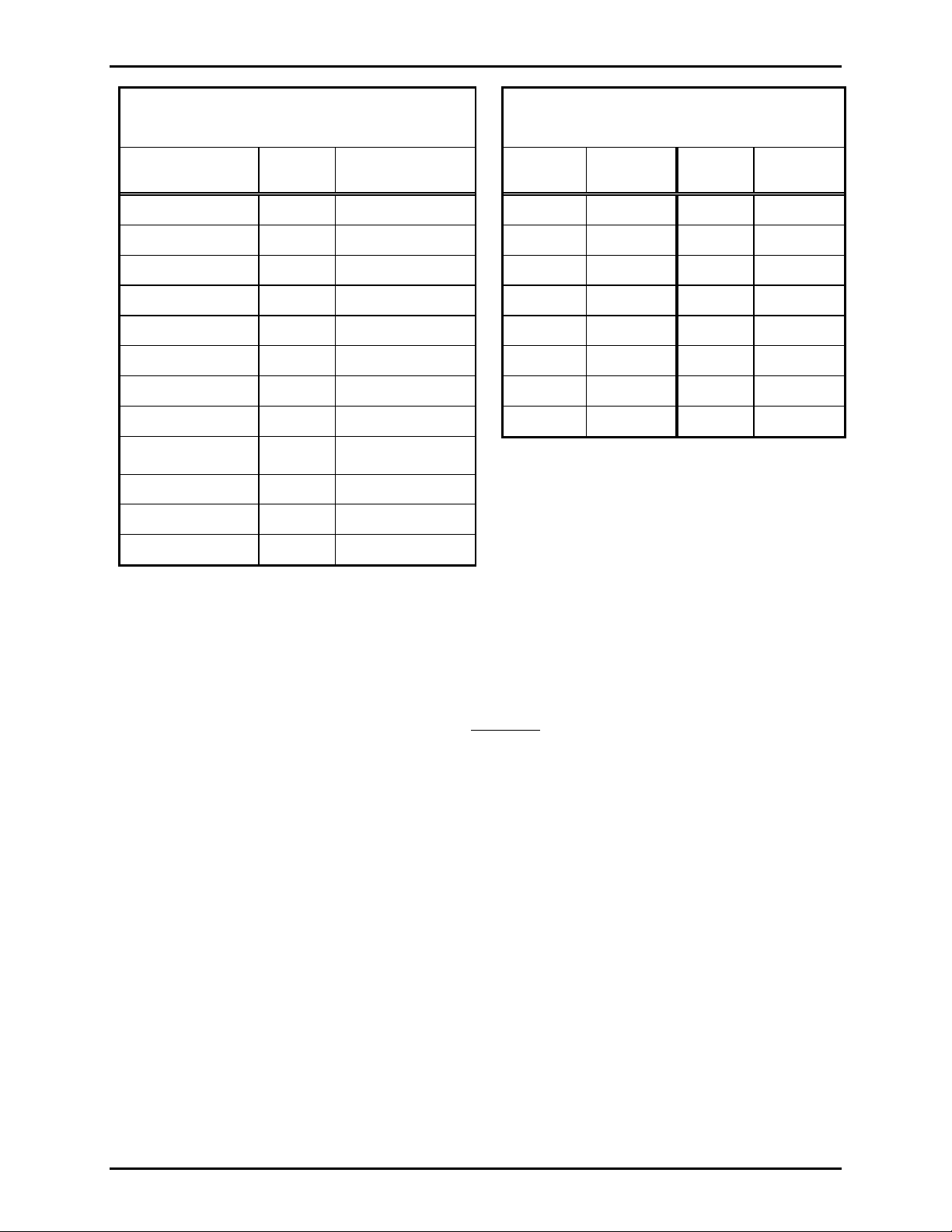
Table 1. Connections Wiring
®
Page/Party
Audio Line
System Cable
Terminal
System Cable
Color Code
Page Line (L1) 1 Red/blue
Page Line (L2) 2 Blue/red
Party Line 1 (L1) 3 Red
Party Line 1 (L2) 4 Tan/red
Party Line 2 (L1) 5 Violet
Party Line 2 (L2) 6 Tan/violet
Party Line 3 (L1) 11 Blue
Party Line 3 (L2) 12 Tan/blue
Party Line 4 (L1) 13 Brown
Party Line 4 (L2) 14 Tan/brown
Party Line 5 (L1) 15 Yellow
Party Line 5 (L2) 16 Tan/yellow
GAI-Tronics 8- or 16-conductor cable is
required.
To attach the wires to the plug:
Table 2. Wiring
Access Panel Connections
Access
Panel
#1 (+) 1 #5 (+) 9
#1 (-) 2 #5 (-) 10
#2 (+) 3 #6 (+) 11
#2 (-) 4 #6 (-) 12
#3 (+) 5 #7 (+) 13
#3 (-) 6 #7 (-) 14
#4 (+) 7 #8 (+) 15
#4 (-) 8 #8 (-) 16
One No. 18 AWG twisted pair cable is required for
Terminal
Access
Panel Terminal
each access panel.
1. Turn the plug screws counterclockwise several times to open the terminal.
2. For optimum wire connection, crimp a ferrule on the end of each wire, then insert the ferrule into the
plug. If not using a ferrule, verify that there are no strands
of wire extruding from the plug after the
wire is inserted.
3. Secure the wire by turning the screw clockwise.
4. Gently pull on the wire to verify that the wire is secured tightly in the plug.
5. After all wires are terminated, insert the plug into the receptacle and then tighten the screws on either
end of the pl ug.
\\s_eng\gtc proddoc s \st andard iom s - current release\42004 instr. m anuals \ 42004-669l2e. doc
07/07
Page 8

Pub. 42004-669L2E
SSM110 Card Rack Assembly Installation, Oper ation, Maintenance Manual Page: 6 of 26
Installing Pl ug-in PC Boards
WARNING
Remove power before i nse rting or remov i ng t he pl ug -i n printed cir cuit
boards. Failure to adhere to t his war ni ng wi ll r esult in equip me nt d a mage.
Insert each PC board into the card rack by aligning the edge of the board with the card rack guides and
pushing the card into the rack until the board’s front bezel is flush with the front of the card rack. Do not
force the card into the rack if the card is not aligned properly when pushed into the card rack. Move the
card slightly from side to side or up and down until the rear connector is aligned, and then press the card
until it is properly seated. Tighten the screws on the top and bottom of each board’s front bezel to secure
the board in the card rack. Each board must be installed into the proper card slot as shown in Figure 2.
The following printed circuit boards are included:
Master Control U nit (MCU )—Contai ns th e centra l processing t hat c oord inates a ll operations as d efin e d
by its software configuration file. The MCU maintains communication with all other cards in the card
rack and with SmartSeries devices located throughout the system. See the MCU card’s publication for
additional in for ma tio n o n the MCU’s operatio n and capabilities. A list of publications is found in the
Reference Material Section.
Page/Party
card supports up to 200 SmartSeries stations and an unlimited number Page/Party
®
Interface (PPI)— Interfaces SmartSeries and Page/Party® stations to the system. Each PPI
®
stations. See the
Reference Material Section for additional information on the operation and capabilities of the PPI card.
Access Panel Interface (API)—I nt erfaces the access panels to the system. The API card supports up to
eight ac c es s pa nels. See th e Reference Materi al Sect ion for additi onal i nformat ion on the op eration and
capabilities of the AP I c ard.
Power
The card rack contains a plug-in power supply, which is installed in the far right card slot. Each power
supply is installed in the same fashion as the plug-in cards mentioned above. A 6-foot modular ac power
cord is provided with the card rack. Plug one end of the cord into the mating receptacle on the side of the
card rack and plug the other end into a standard 15A power receptacle.
\\s_eng\gtc proddoc s \st andard iom s - current release\42004 instr. m anuals \ 42004-669l2e. doc
07/07
Page 9

Pub. 42004-669L2E
SSM110 Card Rack Assembly Installation, Oper ation, Maintenance Manual Page: 7 of 26
Installing SmartSeries Amplifiers
Each SmartSeries station requires installation of a handset or a speaker amplifier. Prior to installing the
amplifier in the enclosure, set each amplifier’s address. A unique address must be set for each amplifier
within a zone. The installer should document each station’s amplifier address, the type of station
installed, a description of the station’s location and the speaker level needed. This information is needed
during system startup.
Address
Type
Description
Speaker Level
Speaker Level Noise Condition Approximate dB Level
Quiet Office Area 30-60
Normal Production Floor 60-90
Loud Turbine Room 90 & above*
No SPKR No Speaker Connected 0
The address is a unique hexadecimal number assigned to a SmartSeries station.
All stations connected to the same PPI card must have a unique address.
The type of stations being used at that location. The type could be a Model 701902 or 701-802 SmartSeries Handset or
a Model 751-901 or 751-801 SmartSeries
Amplifier.
This is a brief d es c ription of th e s tation’s locatio n. T his descript ion will appear on
the printer, to help locate the station. The description can be a maximum of 40
characters in length.
This will be used to program the speaker volume. The following is a description of
the volume level settings.
*NOTE: In extreme ly no isy a reas a visu al ind i c ator may be re quired.
Setting the Amp lifier Address
Two switches are used to set the station address: low address setting and high address setting. Each
switch contains 16 settings, labeled 0-F.
The amplifier address is determined by the high address setting followed by the low address setting. For
example, to assign an address of 05, the high station address is set to 0 and the low station address is set
to 5.
1. Locate the low station setting and the high station setting on the left side of the amplifier.
For Models 701-802, 701-804, and 751-801: Refer to designators 2 and 3 on Figure 4 for a speaker
ampl ifier or designators 7 a nd 8 on Figure 5 for a hands et amplifier.
For Models 701-902, 701-904, and 751-901: Refer to designators 2 and 3 on Figure 6 for a speaker
amp lifi er or Figure 7 desi gnators 2 and 3 f or a handset a mplif ier.
2. Rotate the high switch and the low switch to set the desired address. A small arrow on each switch
indicates the setting. Valid address settings are 05 to FE.
OTE: Do not adjust any ot her controls o n the amplifier. These controls are fac to ry s et a nd wi ll
N
affect station perfor manc e i f improperly adjusted.
\\s_eng\gtc proddoc s \st andard iom s - current release\42004 instr. m anuals \ 42004-669l2e. doc
07/07
Page 10

Pub. 42004-669L2E
SSM110 Card Rack Assembly Installation, Oper ation, Maintenance Manual Page: 8 of 26
Figure 4. Speaker Amplifier - Reference for Model 751-801
Figure 5. Handset Amplifier - Reference for Models 701-802 and 701-804
\\s_eng\gtc proddoc s \st andard iom s - current release\42004 instr. m anuals \ 42004-669l2e. doc
07/07
Page 11

Pub. 42004-669L2E
SSM110 Card Rack Assembly Installation, Oper ation, Maintenance Manual Page: 9 of 26
Figure 6. Speaker Amplifier - Reference for Model 751-901
Figure 7. Handset Amplifier - Reference for Models 701-902 and 701-904
\\s_eng\gtc proddoc s \st andard iom s - current release\42004 instr. m anuals \ 42004-669l2e. doc
07/07
Page 12

Pub. 42004-669L2E
SSM110 Card Rack Assembly Installation, Oper ation, Maintenance Manual Page: 10 of 26
Operation
Page Line Prioriti es
The Smar tSer ies system uses a p rior ity scheme to co ntrol au dio broadcasts from the system speakers if
multiple sources are attempting to access the paging speakers. This means that if a page is made from a
device with a higher priority, an in-progress page from a lower priority device is discontinued or muted.
The priorities, which are configurable, ensure that the most important messages gain access to the page
line first. All SmartSeries stations and access panels are assigned a page priority during the system
conf iguration process. The ADVANCE Console and WinSCP3 software packages available from GAITron ic s are use d to co nfigure and install thes e p aramet e rs.
Access P anel Operator
The access panels available from GAI-Tronics are versatile and allow the operator to communicate and
monitor the status of the syste m. The access panel i ncludes a handset for paging, a ser ies of l ighted p u sh
but tons, a buz zer, and a n op tio nal text dis play. The ha ndset is use d for pagin g and p ar ty line
communication. The buzzer sounds to alert the operator when new system information is received. The
information is listed on the text display (if present). The push-button switches are used by the operator to
perform the following functions:
• Initiate voice pages • Select and reset fault condition messages
• Route voice pages • Check access panel LEDs
• Acknowledge system status
Paging
Complete the following steps to make a page announcement from an access panel:
1. Lift the handset from the cradle.
2. Press and hold the handset pressbar.
3. Speak directly into the microphone to broadcast your announcement over the loudspeakers.
4. Release the handset pressbar and return the handset to the cradle.
Lamp Tes t Feature
The lamp test feature is used to verify that the access panel indicators and display are functioning
properly. Wh en th e L
the panel buzzer sounds. The
AMP TEST push button is pressed, the switch indicators and display illuminate and
LAMP TEST, ACK/NEXT and PREVIOUS push buttons may not include an
indicator, depending on the model.
\\s_eng\gtc proddoc s \st andard iom s - current release\42004 instr. m anuals \ 42004-669l2e. doc
07/07
Page 13

Pub. 42004-669L2E
SSM110 Card Rack Assembly Installation, Oper ation, Maintenance Manual Page: 11 of 26
Field Stati on User
GAI-Tronics offers a full product line of stations designed to allow personnel to communicate throughout
the facility. By using one of the many available models of field stations, personnel can make a voice page
and provide instructions to their co-workers. Personnel can also request communication on the party line.
Party line conversations are private in the sense that they are not broadcast over the system speakers;
however, anyone may join the conversation by picking up the handset and selecting the same party line.
Page Line and Part y Line Operation
Complete the following steps to make a page announcement from a field station.
1. Lift the handset from the cradle.
2. If party line conversation is desired, rotate the selector switch to an unoccupied party line.
3. Press and hold the handset pressbar.
4. Speak directly into the microphone to broadcast your announcement over the loudspeakers.
5. Rel ease the hands et pressb ar , and if requested, wait for a r esponse.
The paged individual(s) responds by picking up a station handset and turning the selector switch to the
requested part y line. Par ty line c ommunicatio n, wh ich is f ull du plex , is n ot broadcast over the syste m
speakers. Other individual(s) can also pick up a handset and join the conversation at any time. Always
return the handset to the cradle following a page or a party line conversation.
\\s_eng\gtc proddoc s \st andard iom s - current release\42004 instr. m anuals \ 42004-669l2e. doc
07/07
Page 14

Pub. 42004-669L2E
SSM110 Card Rack Assembly Installation, Oper ation, Maintenance Manual Page: 12 of 26
Optional Ancillary Equipment
Incorp ora ting t he optional equipment dis c ussed be low can expand the standard featu res of the S SM1 10
Card Rac k. The c onfigur ation of the SS M Card Ra c k ( quantit y/t ypes of int erfa ce cards) and de sired
system features are the determining factors when selecting ancillary equipment to be used to with the
SSM Card Rack. Refer to drawing No.73158 listed in the Reference Material section for typical
interconnections between ancillary equipment and the SSM110 Card Rack. For additional information
and to purchase ancillary equipment please contact a GAI-Tronics representative.
Audio Mes senger Interface
The Audio Messenger Interface (AMI) tone/speech generator broadcasts live pages, pre-recorded alarm
tones, and pr e-recorded sp eech mes s a g es. T he Audi o Messenger Interface Confi guration Tool (ACT)
software is used to define and change configurations for the AMI, and is included with all models of
AMI. To retrieve configurations and play audio messages, the AMI accesses a digital card preprogra mme d with th e AMI F act ory Def ault configuratio n. All audio is i n MP3 f ormat and cust om sp e e ch
messages can be recorded and configured for use with the AMI.
The AMI includes eight configurable inputs and outputs. Typically, the inputs are configured to activate
alarm/process tones and/or pre-recorded speech messages, mute audio playback, and reset alarms. The
outputs are typically used to activate remote alarm systems, interface to automated processes, interface to
paging equipment, etc.
The Model 10959-103 AMI provides the ability to perform live speech pages from a telephone. For this
feature to function, the AMI must be connected to an analog station port of a PBX type telephone system,
or directly to a Central Office telephone line on the public switched telephone network (PSTN). To
prevent feedback, the AMI includes a built-in feedback eliminator. With this feature enabled, incoming
telephone pages are recorded and stored until the telephone connection is terminated. After the
connection is terminated, the AMI broadcasts the page. The delay between the recording and playback of
the page eliminates any possibility of feedback.
®
The Model 10959-103 includes a Page/Party
cap ability to broadcast any a udio g e n erated by th e AM I on a G AI - Tronics Page/Par ty
coupled with a telephone interface card, the Page/Party
duplex line communications. Additionally, AMI models that include the 33-ohm Page/Party
system interface card. This interface card provides the
®
card provides telephone callers access to full-
®
system. When
®
interface
card allow a telephone caller to direct the telephone call to a specific party line.
Building Entrance Protection B arrier
The Model 10434-202NA Building Entrance Protection Barrier provides secondary protection from
signal line transients and over-voltage conditions that may cause serious damage to indoor
equipment or injury to personnel.
\\s_eng\gtc proddoc s \st andard iom s - current release\42004 instr. m anuals \ 42004-669l2e. doc
07/07
Page 15

Pub. 42004-669L2E
SSM110 Card Rack Assembly Installation, Oper ation, Maintenance Manual Page: 13 of 26
System Status and Status R eporting
The syste m s tatus indicators notif y the oper ator of system e vents an d troubl e conditi ons. S ystem status
can be presented in several ways, depending on the system configuration. The following methods are
available:
• Text messages on the access panel display (if equipped with a display)
• Access panel indicators that turn on and off
• Access panel buzzers that start and stop
• Lights on cards in the card rack that turn on and off
• Text messages that print on a printer
• Device fault and restore events
• Operational events (page line activity)
Status Mess ages
NOTE: Not all access panels are equipped with displays. The following section pertains to access panels
that are equipped with d isplays.
The system sends status messages to the operator. Status messages are text messages that are indicated on
the access panel display and printed on the printer. The system configuration specifies which messages
ar e s ent to t he op erator and whether th e y ar e repor ted o n the system pr inter , a n access panel dis play, or
both. The configuration further specifies which types of messages sent to access panels require the
operator to acknowledge them. The actual configuration of the status messages will be determined at
system startup.
Display History Buffer
The system puts messages in a queue called the History Buffer. Messages that require status message
reporting are sent from the history buffer to the access panels. The system can accommodate a maximum
of two history buffers, and each can store up to 100 messages. Each history buffer is associated with one
specific acc ess p anel that contai ns any of the follo wing : a display, a buzzer i ndicator, a buzzer flas h
indi c ator, or a history le vel status indica tor.
Messages ar e arranged with in a history buf fer accordi ng to a priority sch e me.
Group 1 messages are messages that are waiting for acknowledgment. The messages are arranged by
type in descending order of priority. Within each type, the messages are arranged oldest to newest.
1. Trouble messages
2. Restore messages
Group 2 consists of messages that do not require acknowledgment and messages that have been
acknowledged, but the condition persists. Messages are arranged by the following types in descending
order of p riority.
1. Trouble messages
2. Operatio nal messa ges (page a ctivity)
3. Restore messages
\\s_eng\gtc proddoc s \st andard iom s - current release\42004 instr. m anuals \ 42004-669l2e. doc
07/07
Page 16

Pub. 42004-669L2E
SSM110 Card Rack Assembly Installation, Oper ation, Maintenance Manual Page: 14 of 26
When a Group 1 message is acknowledged, it moves to Group 2. Messages are acknowledged by using a
switch on the access panel. Acknowledging a message on one access panel does not affect messages on
other access panels.
Messages lea ve the hist ory bu ffer whe n any of the f ollo wing occu r:
• The condition restores
• An access panel operator presses the trouble remove switch (Group 2 messages only)
• The history buffer reaches its maximum capacity
NOTE
If the history buffer reaches its maximum capacity, the system first discards Group 2 messages starting
with the lowest priority type messages, oldest to newest. The system proceeds to the next higher priority
type, again discarding messages from oldest to newest. When there are no Group 2 messages, the system
discards Group 1 messages starting with the lowest priority type, from oldest to newest.
Access P anel Display
An access p anel may have on e d isp lay, w ith a ma ximum of two displays per s ys tem. E ach display must
be configured with a history buffer. The system will display one text message at a time. The message is
displayed unless a higher priority message preempts it. The operator can scroll through Group 2
messages if there are no Group 1 messages.
There are t w o swit ch es u sed for s cro l li ng: PREVIOUS
acknowledges Group 1 messages. If there are no Group 1 messages, the A
throug h any Group 2 messages in t he histor y buffer. A
and ACK/NEXT. The ACK/NEXT switch
CK/NEXT switch w ill scroll
CK/NEXT displays the next message downward in
the buffer within the Group 2 priority scheme (the oldest message in the next level down). PREVIOUS
moves to the prior message within Group 2 messages.
System Printer
There is a maximum of one printer per system. The system sends messages to the printer when certain
conditions occur. The types of messages to print are configurable. This allows the operator to have a
chronological record of events that occur in the system. If the operator acknowledges a message, the
acknowledgment message prints.
Contents of a Status Message
The system displays or prints one status message at a time. The types of messages displayed are
dependent upon your configuration; however, the messages could include the following:
• Device fault and restore events
• Operatio nal events ( pag e or pa r ty lin e acti vity)
\\s_eng\gtc proddoc s \st andard iom s - current release\42004 instr. m anuals \ 42004-669l2e. doc
07/07
Page 17

Pub. 42004-669L2E
SSM110 Card Rack Assembly Installation, Oper ation, Maintenance Manual Page: 15 of 26
Device Fault Messages
When a trouble condition is detected in the system, a Device Fault message is printe d. The follo w ing is
an example of a device fault message.
****************** Device Fault ********************
01-Jan-07 10:30.00 AM
Warehouse Zo ne
Handset Stat ion in Office
(This table is shown as an example only)
The information provided on the device fault message includes the following:
• 01-Jan-07 10:30.00 AM - Date and time of event
• Warehouse Zone - Indicates the zo ne where the trouble exists
• Handset Stat ion in Office - Description of device that is faulted
Device Restore Messages
When a trouble condition is corrected, a Device Restore mess age is printed. The fol lowing is an example
of a d e vice restore mes sa ge.
**************** Device Restore********************
01-Jan-07 10:31.00 AM
Warehouse Zo ne
Handset Stat ion in Office
(This table is shown as an example only)
Page Message s
When a page is generated from a SmartSeries handset station, a Page Start messa ge is p rint e d. The
following is an example of a page start message.
****************** Page Start ********************
01-Jan-07 10:30.00 AM
Warehouse Zo ne
Supervisor’s O ffi ce Handset
(This table is shown as example only)
The information provided on the Page Start message includes the following:
• 01-Jan-07 10:30.00 AM - Date and time of event
• Warehouse Zo ne - Indicates the zone where the page was generated
• Supervisor’s O ffi ce H a nds et - D escription of device that generated the page
\\s_eng\gtc proddoc s \st andard iom s - current release\42004 instr. m anuals \ 42004-669l2e. doc
07/07
Page 18

Pub. 42004-669L2E
SSM110 Card Rack Assembly Installation, Oper ation, Maintenance Manual Page: 16 of 26
System Startup and Shutdown
The system administrator can start, configure, restart, and stop the system. System startup includes cold
start and warm start.
Cold Starting the System
Cold start the system from the power-off state. Complete the following steps to cold start the system:
1. App ly power to all fi e ld st ations. W hen stations a re powere d they are operational alth ough they do
not communicate with the card rack until the cold start completes.
2. Apply power to the card rack. The visual indicators on the MCU card illuminate. The O
indi c ators on t he PP I c ar d illuminat es when t he sys tem is ru nnin g.
NLINE
Warm Starting the System
Warm start the system from the power-on state by pressing the RESET button on the MCU bezel in the
card ra c k. Field st ations re main oper ational during t he warm start.
System Shutdown
The system is shutdown by removing power from the card rack. Field stations continue limited operation
until their power is removed.
\\s_eng\gtc proddoc s \st andard iom s - current release\42004 instr. m anuals \ 42004-669l2e. doc
07/07
Page 19

Pub. 42004-669L2E
SSM110 Card Rack Assembly Installation, Oper ation, Maintenance Manual Page: 17 of 26
The Programming Process
NOTE: This section is intended to give a general overview of the system programming process. Due to
the critical nature of the system sof tware confi guration and it s effect on re liabl e and proper s yste m
operation, the configuration process should be coordinated by GAI-Tronics technical personnel or
performed by a certified system administrator. Contact GAI-Tronics Service at 1-800-492-1212 for
technical assistance relating to system configuration or certification training.
The Master C ontr ol Unit ( MCU) c ar d c ontains t he system oper ating s of tware and th e system
configuration file. The configuration file c ontains the data that defi nes the sys tem’s physi c al and
operational characteristics. During system startup, the MCU initializes and automatically reads the
configuration file, and then sets the system operation to match the parameters.
The System Manger can change configuration by using the ADVANCE Console and WinSCP3 software
packages. The ADVANCE Console creates and maintains the software configuration file by
methodically setting data values. Graphical representations of the system components are used along
with various data entry forms and settings.
Using t he ADVANCE Console doe s not requ ire a connection to the MCU. The System M ana ger can
work on a configuratio n at a ny pace on a PC . There is no need to set a ll of the p ar ameter’s data values in
one session. The System Manager is simply working on a configuration that is independent of any other
conf igurat ion that may exis t or be act i v e in an operating system.
When the Syst em Manag er is fi n ish ed entering all th e da ta , t he ADVANCE C o nsol e fi le is translat ed (or
compiled). The resulting file is called the system configuration file. To save the configuration file onto
the MCU, the System Manager’s computer is connected to the MCU using an Ethernet network
connect ion. The c onne c tio n can be made loc ally us ing a network c rossover patch c able.
The file is loaded onto the MCU using the WinSCP3 application. The purpose of the WinSCP3 program
is to provide a means of accessing the MCU’s hard drive for file transfer from the System Manager’s
computer. The WinSCP3 program does not have the configuration capabilities of the ADVANCE
Console.
The system software must be re-configured when any changes are required such as the following:
• Changes in system operation that relates to voice paging.
• Changes to alarms act ivation/ res et meth ods or ala rm annunciat ion parameters.
• Adding or re moving SmartSeries stations, access panels , or I/O dev ices.
• Changes to equipment or location identifications.
• Changes in system status reporting.
OTE: The programming process described above is one-way only. It is not possible to retrieve the
N
conf iguration data fil e from the M CU in a for mat, which can b e v iewe d and e dit e d.
\\s_eng\gtc proddoc s \st andard iom s - current release\42004 instr. m anuals \ 42004-669l2e. doc
07/07
Page 20

Pub. 42004-669L2E
SSM110 Card Rack Assembly Installation, Oper ation, Maintenance Manual Page: 18 of 26
ADV ANCE System Files
As stated earlier in this manual, the ADVANCE Console program is used for software programming of
the system. There are two important file types used with the ADVANCE Console program:
The .hot F ile
The file that is created, opened, or saved by the ADVANCE Console program uses the file extension .hot.
The file name preceding the .hot extension can contain any characters recognized by Windows as a valid
file name. Generally the <filename>.hot is a descriptive name identifying the system or systems that it is
being used for. The .hot file cont ains the data of a ll syst e m a ttribu tes and parameters that ar e entered
using the various user screens in the ADVANCE Console program.
The .hot file ca n onl y be op e ned, edited, and saved usi ng ADVANC E Console. Wh e n cha nges are made,
the file must be sa ved or the chang es are lost. The f ile can be save d to an y f old er, rena me d, or deleted
usin g windows ex pl orer aft er it is in itially s aved using ADVANCE Console. The fi le size obviou sly
depe nds on th e content of the syst e m bein g configured but generally is less than 1 Mb making it sma ll
enough t o be e- mail e d or tra nsferred t o any read ily a vailabl e storag e d e vice.
The .cfg Fil e
The .hot file described above is not directly used by the MCU to operate the system. It must first be
compiled using ADVANCE Console. The resultant file, after compiling, is named advance.cfg. This file
is stored on th e M CU hard drive and is us e d by t he MCU oper ating syst e m t o exec ut e all th e system
functions.
The MCU only recognizes the file name advance.cfg. If the file is misspelled in any way the system will
not function.
OTE: The filename is case sensitive and must be all lower case.
N
\\s_eng\gtc proddoc s \st andard iom s - current release\42004 instr. m anuals \ 42004-669l2e. doc
07/07
Page 21

Pub. 42004-669L2E
SSM110 Card Rack Assembly Installation, Oper ation, Maintenance Manual Page: 19 of 26
Process Flow
The following is an overview showing the typical steps in programming an ADVANCE System.
Action Description
1. Gather information.
2. Run the ADVANCE Console.
Software program.
3. When completed, s ave the
conf iguration da tabas e fi le.
4. Compile the <filename>.hot file
5. Connect the programming PC to
the MCU.
6. Run W in SCP3 Progr am.
7. View the har d drive contents of
the MCU.
Collect hardware and operation details that apply to the new or
cha nged s yst e m c onfigurat ion.
The System Administrator defines all system hardware and sets
all sys tem operating pa r ameters for th e s ys tem using graphical
interface screens.
All changes are saved in <filename>.hot.
The console program generates a file folder for each system
defi ned in the configur ation. The fol ders ar e s aved a t the
specified file location. Each folder contains a file named
advance.cfg.
The System Administrator attaches an Ethernet crossover cable
from the PC to the MCU.
The Syst e m A dmin istrat or sta rts the Win S CP3 Progr am an d
opens a session to the MCU. If the system contains more than
one MCU, a differ ent s ession is opened wit h each MC U.
Multiple sessions can be open at the same time.
Navigate to the root/home/advance direc tory on t he MCU.
This is where the configuration file must be saved.
8. On the programming PC,
navigate to the folder containing
the new configuration file
(created above).
9. Eith er re name or del ete t he
existing advance.cfg file on the
MCU.
10. C opy co nfiguration file onto the
MCU har d dri ve.
11. The system will automatically re-
start a nd execute the new system
configuration.
Navigate to the d irectory created b y the ADVAN CE C ons ole
program. This is where the new configuration file is saved.
The System Administrator removes the advance.cfg file from
the MCU hard driv e. It can be also saved as an ar chi ve in cas e
of a p roble m wit h the n e w configu ra tion.
The System Admin i st rato r c opi es t he advance.cfg file to MCU.
\\s_eng\gtc proddoc s \st andard iom s - current release\42004 instr. m anuals \ 42004-669l2e. doc
07/07
Page 22

Pub. 42004-669L2E
SSM110 Card Rack Assembly Installation, Oper ation, Maintenance Manual Page: 20 of 26
Maintenance
General Information
Contact GAI-Tronics Service at 1-800-492-1212 for technical assistance.
Troubl eshooting Guide
System Hum or Buzz
Hum or buzz on the paging speakers is usually due to a short circuit to ground on one of the two page line
conductors in the system cable. This condition is indicated on the access panel display and the PPI card
in the card rack.
To correct the problem, locate the source of the ground. Using an ohmmeter, check various junction
point s of the syst e m w i ring to de termine in which direction the grou nd ca n be located. L oc ate t he gr ound
by going from one junction point to another and disconnecting the affected circuit. The fault could be
within a plug-in amplifier. However, most ground circuits occur in improper terminations or are caused
by small strands protruding from an improperly lugged wire.
Another sour c e of grounds or near-grounded c ircui ts is junctio n b oxes filled or partially f illed wit h wat er.
In many cases, there are deposits in the boxes, which, when combined with water, produce conductive or
corrosive solutions. These deposits cause leakage between circuits and can corrode the wire and
terminals.
Isolation of f ield wir ing ma y be necess ar y f or tes t purposes. W hen is olating a por tion of the system fr o m
the card rack, a 33-ohm 1/2-watt resistor must be connected across L1 and L2 of the page and party lines
to provide the proper audio line balance resistance. Remove this resistor after completion of the tests.
OTE: The same tests also apply to the party lines.
N
Static Charges
In many normal installations, a static ac voltage may be read from the conductors of the page line circuits
to ground. In many cases this voltage may be as high as 50 volts or more. This voltage is induced into
the circuits by capacitance to the ac power circuit (generally carried in the same cable, and also from
power cables paralleling communication cables). This voltage is inconsequential and can be ignored.
Problems would only occur if one side of the page circuit becomes grounded.
Audio Voltag e
In a properly operating system, audio voltage read across the page and party line circuits (L1 and L2) will
be 1 to 1.5 V
when an audio signal is present. The voltage will be proportional to the loudness of the
RMS
person’s voice using the handset.
\\s_eng\gtc proddoc s \st andard iom s - current release\42004 instr. m anuals \ 42004-669l2e. doc
07/07
Page 23

Pub. 42004-669L2E
SSM110 Card Rack Assembly Installation, Oper ation, Maintenance Manual Page: 21 of 26
Troubleshoo ting the Card Rack
Symptom Action
Power LEDs on MCU card
do not illuminate.
Verify proper connection of ac power cord. Verify ac power is applied.
Verify the MCU is fully seated in the card rack.
Call for service of the power supply.
Plug-in cards do not operate
in one of the slots.
Check slot with a known good plug-in card.
Call for service of the card rack backplane.
Master Control Unit (MCU) Status Indicators
LED Description (When ON)
-12V
+12V
+5V
The card rack is providing –12 volts dc to the MCU.
The card rack is providing +12 volts dc to the MCU.
The card rac k is provid ing +5 volt s dc to the MCU.
BEEP (red) This LED simulates the CPU module speaker function. The LED emits light instead of a
speaker emitting sound.
N
OTE 1: The LE D may f lash O N brie f ly when th e PC beg ins b ooti n g, otherwise, this
LED is OFF. If applicable, your system manual lists situations where this LED should
be ON.
OTE 2: If the CPU Module detects an error during boot-up, this LED will flash more
N
than once. In this error condition, the CPU Module generates, a one-time “beep code” to
aid in diagnosing the fault. Momentarily pressing the reset button will cause the beep
code to repeat.
LINK Shows Ethernet network status. The MCU has established a communications link with
another Ethernet network device.
ACT Shows Ethernet network status. The MCU detects activity on the attached Ethernet
cable.
BP (red) The MCU is using the data bus in the card rack.
The ca rd rack is s ometimes re ferred to as “b ackplane,” w hich g ives t his LE D its
abbrevia tio n ( B P).
SPD This LED operates in conjunction with LINK LED to indicate the speed of the Ethernet
network connection.
LINK
(On) SPD (Off) = 10 Mb Ethernet connection
LINK
(On) SPD (On) = 100 Mb Ethernet connection
LINK
(Off) SPD (On/Off) = no network connection established
SEC (red)
The MCU is accessing the CompactFlash
®
card connected to the secondary IDE
controller.
PRI (red) The MCU is accessing the hard disk drive connected to the primary IDE controller.
B7, B6, B5,
B4,
B3, B2,
or B0
B1,
These LEDS are referred t o as the Port 80 LEDs. They are used to show diagnostic
inf orma tion t hat can be u sed b y f act ory tra i n ed techni c ians as a troub leshoot ing aid.
\\s_eng\gtc proddoc s \st andard iom s - current release\42004 instr. m anuals \ 42004-669l2e. doc
07/07
Page 24

Pub. 42004-669L2E
SSM110 Card Rack Assembly Installation, Oper ation, Maintenance Manual Page: 22 of 26
Troubleshoo ting the MCU
Symptom Action
The LEDs on front
bezel do not illuminate.
Check to ensure that the MCU is inserted correctly into the card rack. Check
that power is applied to the card rack.
Call for service for the MCU and/or the card rack.
System does not boot. Call for service of the MCU.
Date and time settings
do not stay current after
Check the battery connection on the MCU. MCU battery may need to be
replaced.
a period of system
power interruption.
Access Pan el Interfac e (API) Ca rd Status Indi cators
LED Status Description
ON LINE On
The MCU is running and is configured to recognize the
API.
Off
The API is not receiving power from the card rack or the
MCU is not properly configured to recognize the API.
FAULT On
The MCU has detected at least one failure in any of the
access panels a ttached to the API.
Off
No failures are detected in any configured access panel.
Troubleshoo ting the API Card
Status/Message Meaning Suggested Action
ON LINE LED
does not
illuminate.
1. Power is not applied
to the card.
• Verify power is applied to the card rack.
• Verify the API card is properly seated in the card
rack.
• Call f or service.
2. A component failure
has oc cur red.
3. Card is not in the
configuration.
• Replace the API Card with a spare.
• Call f or service.
• Verify the proper card address and board ID settings
on the API.
• Veri fy proper MC U c onfigur ation as listed in s ystem
manual.
• Call f or service.
\\s_eng\gtc proddoc s \st andard iom s - current release\42004 instr. m anuals \ 42004-669l2e. doc
07/07
Page 25

Pub. 42004-669L2E
SSM110 Card Rack Assembly Installation, Oper ation, Maintenance Manual Page: 23 of 26
Status/Message Meaning Suggested Action
FAULT LED is
illuminated.
No audio on a
page resource.
Audio low on
page line
1. No data
communication.
2. A component failure
has oc cur red.
3. MCU c onfiguration
is not correct.
1. The audio path is
impaired.
2. A component failure
has oc cur red.
3. Problem with access
panel microphone or
pre-amp section.
1. The volume levels at
the access panels are
improperly set.
• Verify cable integrity from API to all associated
access panels.
• Call f or service.
• Replace the API card.
• Call f or service.
• Veri fy the proper MCU configu ra tion as listed in
system manual.
• Call f or service.
• Verify the API card is properly seated in the card
rack.
• Verify exter na l equ ipment connected properly.
• Call f or service.
• Replace the API card.
• Call f or service.
• Replace access panel.
• Call f or service.
• Incr ease t he volume of the acces s panels in the
affected a rea (via system configuration).
• Call f or service.
No audio on a
party line
Audio l ow on a
party line
2. A component failure
has oc cur red.
3. Problem with access
panel microphone or
pre-amp section.
1. The audio path is
impaired
2. A component failure
has oc cur red
3. Problem with access
panel microphone or
pre-amp section.
1. A component failure
has oc cur red.
2. Problem with access
panel microphone or
pre-amp section.
• Replace the API card.
• Call f or service.
• Replace access panel.
• Call f or service.
• Verify the API card is properly seated in the card
rack.
• Verify exter na l equ ipment connected properly.
• Call f or service.
• Replace the API card.
• Call f or service.
• Replace access panel.
• Call f or service.
• Replace the API card.
• Call f or service.
• Replace access panel with spare.
• Call f or service.
\\s_eng\gtc proddoc s \st andard iom s - current release\42004 instr. m anuals \ 42004-669l2e. doc
07/07
Page 26

Pub. 42004-669L2E
SSM110 Card Rack Assembly Installation, Oper ation, Maintenance Manual Page: 24 of 26
Page/Par ty® Inte rface Card (P PI) S tatus In dica tors
LED Status Description
On Line (green) On Card is configur ed an d has p ow er.
Off
Card is not configured properly, the po wer is off, or the card
has f aile d.
RTS (yellow) Blinking System is polling SmartSeries stations.
On Th ere are no Sma rtSeries stations c onfigu red i n the zone.
Off Card is either not configured or the power is off.
EOL FLT (red) On
There is no response from one or more SmartSeries stations
configured as a page line EOL device for this zone.
Off
There are no EOL devices, or all EOL devices configured in
this zone are operating properly.
GND FLT (red) On
Ground fault detection is enabled and a ground is detected on
eith er the page lin e o r the party line.
Off
Ground fault detection is disabled, or no ground fault is
detected.
Troubleshoo ting the PPI Card
Status/
Message
Meaning
Suggested Ac tion
On-Line LED
does not
illuminate.
RTS LED does
not flash.
1. Power is not
applied to the
card.
2. A component
failu re ha s
occurred.
3. C a rd is not in
the
configuration.
1. No external
devices are
configured.
2. A component
failu re ha s
occurred.
• Verify power is applied to the card rack.
• Verify the PPI Card is properly seated in the card rack.
• Call f or service.
• Replace the PPI card with a spare.
• Call f or service.
• Verify the proper card address and PCBA ID settings on
the PPI.
• Veri fy proper MCU configu ra tion.
• Call f or service.
• Veri fy proper MCU configu ra tion.
• Call f or service.
• Replace the PPI card with a spare.
• Call f or service.
\\s_eng\gtc proddoc s \st andard iom s - current release\42004 instr. m anuals \ 42004-669l2e. doc
07/07
Page 27

Pub. 42004-669L2E
SSM110 Card Rack Assembly Installation, Oper ation, Maintenance Manual Page: 25 of 26
Status/
Message
EOL Fault LED
is illuminat e d.
GND Fault LED
is illuminat e d.
No audio i n the
Page/Party
®
zone.
Station receiver
sidetone is high.
Meaning
The EOL station is
not reporting.
A conductor on
the page line or
party line 1 is
grounded.
1. The audio
path is
impaired.
2. MCU
configuration
is not correct.
The page line
balance needs
adjustment.
Suggested Ac tion
• Verify the proper wire connections on terminal block.
• Verify power is applied to the EOL station.
• Verify the EOL station is installed.
• Veri fy the pr oper MCU configuratio n.
• Call f or service.
• Identify which conductor is grounded, by measuring the
resistance to ground of each conductor. Then, remove
ground from the associated conductor.
• Call f or service.
• Verify the proper wire connections on terminal block.
• Call f or service.
• Veri fy the pr oper MCU configuratio n.
• Call f or service.
• Adjust the page balance.
• Call f or service.
Acce ss Panel wit h Display
1. Notify plant personnel of a system shutdown prior to servicing the unit.
2. Disconnect power before connecting external wiring or installing or removing the access panel.
Symptom Action
All access panel indicators are flashing and
the buzzer is sounding.
• Verify that the twisted-pair data cable is properly
connect ed bet ween the access panel and the car d r ack.
• Verify that the card rack is on-line.
Push buttons are not operative.
Verify that the access panel push buttons are properly
configured by the system software configuration.
Switch lamps do n ot illumina te.
• Press the lamp test and replace lamps in any switches
that do not illuminate.
• Verify that the access panel lamps are properly
configured by the system software configuration.
Buzzer d oes not function.
• Press the lamp test and if the buzzer does not sound,
replace the buzzer.
• Verify that the buzzer is properly configured and
recognized by the system software configuration.
Disp lay d oes not func tio n.
Press the lamp test and if the display does not illuminate,
check internal wir ing c o n nect ions.
\\s_eng\gtc proddoc s \st andard iom s - current release\42004 instr. m anuals \ 42004-669l2e. doc
07/07
Page 28

Pub. 42004-669L2E
SSM110 Card Rack Assembly Installation, Oper ation, Maintenance Manual Page: 26 of 26
Recommende d Spare P arts
Model No. Description
69440-101 Ma ster Control Unit PCBA
69255-001 Page/Party® Interface PCBA
69257-101 Access Panel Interface PCBA
RFP8055-001 DC P ower Supply, 70 watt
Ref erence Material
Publication # Model # Description
42004-702L2 69440-101 Master Control Unit Card
42004-608L2 69255-001 Page/Party
42004-680L2 69257-101 Access Panel Interface Card
®
Interface Card
Drawing # Description
72487 SSM110 Card Rack Outline Drawing
73158 SSM110 Maintenance Card Rack Assembly Interconnection Diagram
Specification s
Electrical
Power supply............................................................................Fused at 2 A, 250 V (not user-serviceable)
Input voltage ............................................................................................................... 120 V ac/240 V ac
Total power consumed......................................................................................... 50 VA, 25 W maximum
Input frequency range ................................................................................................................ 50/60 Hz
Input surge current (cold start)....................................................................Less than 25 A peak maximum
AC input power connector (side) .............................................................................. IEC 320-style, 3-pin
Environmen tal
Temperature operating ....................................................................... +32° F to +122° F (0° C to +50° C)
Temperature storage....................................................................................................... -40° C to +85° C
Relative humidity................................................................................................ Non-condensing, 5–85%
Mechanical
Unit dimensions .................................... 10.47 H × 8.55 W × 12.34 D inches (265.9 × 217.2 × 313.5 mm)
Unit weight ................................................................................................................... 10 lbs. maximum
\\s_eng\gtc proddoc s \st andard iom s - current release\42004 instr. m anuals \ 42004-669l2e. doc
07/07
Page 29

Warranty
Equipment. GAI-Tronics warrants for a period of one (1) year from the date of shipment, that any
GAI-Tronics equipment supplied hereunder shall be free of defects in material and workmanship, shall
comply with the then-current product specifications and product literature, and if applicable, shall be fit
for the purpose specified in the agreed-upon quotation or proposal document. If (a) Seller’s goods prove
to be defective in workmanship and/or material under normal and proper usage, or unfit for the purpose
specified and agreed upon, and (b) Buyer’s claim is made within the warranty period set forth above,
Buyer may return such goods to GAI-Tronics’ nearest depot repair facility, freight prepaid, at which time
they will be repaired or replaced, at Seller’s option, without charge to Buyer. Repair or replacement shall
be Buyer’s sole and exclusive remedy. The warranty period on any repaired or replacement equipment
shall be the greater of the ninety (90) day repair warranty or one (1) year from the date the original
equipment was shipped. In no event shall GAI-Tronics warranty obligations with respect to equipment
exceed 100% of the total cost of the equipment supplied hereunder. Buyer may also be entitled to the
manufacturer’s warranty on any third-party goods supplied by GAI-Tronics hereunder. The applicability
of any such third-party warranty will be determined by GAI-Tronics.
Services. Any services GAI-Tronics provides hereunder, whether directly or through subcontractors,
shall be performed in accordance with the standard of care with which such services are normally
provided in the industry. If the services fail to meet the applicable industry standard, GAI-Tronics will
re-perform such services at no cost to buyer to correct said deficiency to Company's satisfaction provided
any and all issues are identified prior to the demobilization of the Contractor’s personnel from the work
site. Re-performance of services shall be Buyer’s sole and exclusive remedy, and in no event shall GAITronics warranty obligations with respect to services exceed 100% of the total cost of the services
provided hereunder.
Warranty Periods. Every claim by Buyer alleging a defect in the goods and/or services provided
hereunder shall be deemed waived unless such claim is made in writing within the applicable warranty
periods as set forth above. Provided, however, that if the defect complained of is latent and not
discoverable within the above warranty periods, every claim arising on account of such latent defect shall
be deemed waived unless it is made in writing within a reasonable time after such latent defect is or
should have been discovered by Buyer.
Limitations / Exclusions. The warranties herein shall not apply to, and GAI-Tronics shall not be
responsible for, any damage to the goods or failure of the services supplied hereunder, to the extent
caused by Buyer’s neglect, failure to follow operational and maintenance procedures provided with the
equipment, or the use of technicians not specifically authorized by GAI-Tronics to maintain or service the
equipment. THE WARRANTIES AND REMEDIES CONTAINED HEREIN ARE IN LIEU OF AND
EXCLUDE ALL OTHER WARRANTIES AND REMEDIES, WHETHER EXPRESS OR IMPLIED BY
OPERATION OF LAW OR OTHERWISE, INCLUDING ANY WARRANTIES OF
MERCHANTABILITY OR FITNESS FOR A PARTICULAR PURPOSE.
Return Policy
If the equipment requires service, contact your Regional Service Center for a return authorization number
(RA#). Equipment should be shipped prepaid to GAI-Tronics with a return authorization number and a
purchase order number. If the equipment is under warranty, repairs or a replacement will be made in
accordance with the warranty policy set forth above. Please include a written explanation of all defects to
assist our technicians in their troubleshooting efforts.
Call 800-492-1212 (inside the USA) or 610-777-1374 (outside the USA) for help identifying the
Regional Service Center closest to you.
(Rev. 10/06)
 Loading...