

Page 1

Pub. 42004-135H
GAI-TRONICS® CORPORATION
A HUBBELL COMPANY
Speaker/Horn Installation for
GAI-Tronics Communication Systems
Confidential ity Notice
This manual is provided solely as an operational, installation, and maintenance guide and contains
sensitive business and technical information that is confidential and proprietary to GAI-Tronics.
GAI-Tronics retains all intellectual property and other rights in or to the information contained herein,
and such information may only be used in connection with the operation of your GAI-Tronics product or
system. This manual may not be disclosed in any form, in whole or in part, directly or indirectly, to any
third party.
General Information
Correct mounting and orientation of speakers are critical to the performance of GAI-Tronics
communication systems. Paging speakers used in these systems fall into one of three categories:
Horns supplied with separate drivers and separate, optional mounting assemblies (for the most
accurate orientation)
Horns with internal drivers and optional mounting assemblies
Cone speaker assemblies for wall or ceiling mounting
Speak er Mounting and Wiring
Correct speaker location and orientat ion are cru cia l to ensur e com prehe nsiv e soun d distr ibu tio n in
operating areas. The following are some guidelines:
1. Mount horn-type speakers approximately 8 to 10 feet (2.5 to 3 meters) above the floor and fasten to a
suitable support structure.
2. Do not position speakers so that they are facing each other unless they are more than 50 feet apart.
3. Orient the speaker so that a person standing in the center of the coverage area can sight directly along
its axis of projection. Adjust the orientation of horn-type speakers installed with GAI-Tronics
speaker mounting assemblies vertically and horizontally after the entire assembly is permanently
mounted and wired. Adjust the vertical orientation using the two locking nuts on the U-bracket of the
speaker. Adjust the horizontal orientation using the locknut on the pipe nipple assembly supporting
the mounting bracket adapter.
4. If two speakers are connected to GAI-Tronics SmartSeries and ICS SmartSeries stations, the speakers
should be located in areas with the same ambient nois e level.
GAI-Tronics Corporation 400 E. Wyomissing Ave. Mohnton, PA 19540 USA
610-777-1374 800-492-1212 Fax: 610-796-5954
V
ISIT WWW.GAI-TRONICS.COM FOR PRODUCT LITERATURE AND MANUALS
Page 2

Pub. 42004-135H
Speaker/Horn Installation for GAI-Tronics Communications Systems Page 2 of 8
5. Adjust the speaker output to be 6 to 10 dB louder than the surrounding noise level. It is critical that
the speaker be placed as close as possible to the noise source for the following reasons:
As you move away from a sound source, the sound pressure level drops (attenuates)
approximately 6 dB each time you double your distance from the source. Therefore, if the
loudspeaker and the noise source are close together, both loudspeaker output and noise source
will attenuate at the same rate, maintaining the proportional signal-to-noise ratio.
If the loudspeaker is mounted in an area away from the noise source, the audio will be too loud
near the loudspeaker but not loud enough near the noise source.
GAI-Tronics drivers and mounting assemblies are shipped separately from the horns. See the
accompanying Figure 1, Figure 2, and Figure 3 for mounting assembly details. Also refer to Table 2,
“Mounting Assembly Application Chart” for the correct assembly to be used with each GAI-Tronics
speaker horn.
General Wiring Guidelines
GAI-Tronics recommends its 60021-301 cable where No. 18 AWG wire is acceptable for speaker wiring.
With a maximum outside diameter of 0.285 inches (7.3 mm), it is suitable for conduit, duct, and cable
tray use. It contains a BK/W insulated conductor for the (common) connection and a W/BK insulated
conductor for the 8- or 16-ohm connection.
The 60028-101 3-conductor cable is recommended where the Model 13314 series speaker driver is used
in order to take advantage of the driver’s ground connection.
Positive voltage applied on the positive loudspeaker terminal will move the diaphragm forward. Wire all
speakers in a system so that all diaphragms move in the same direction. To simplify wiring, each
loudspeaker terminal is labeled. Some speakers are labeled 8
COM or 16 COM. These labels
correspond to the labels inside the speaker amplifiers. For those loudspeaker terminals labeled
differently, use the following wiring guideline:
If marked with L1 and L2: L1 is the common terminal. L2 is positive and is connected to either 8 or
16, depending on the speaker rating.
If the loudspeaker has attached cables: The white conductor is common. The black conductor is
positive and is connected to either 8 or 16, depending on the speaker rating.
®
Normally, only one high power horn-type speaker is connected to a GAI-Tronics Page/Party
amplifier.
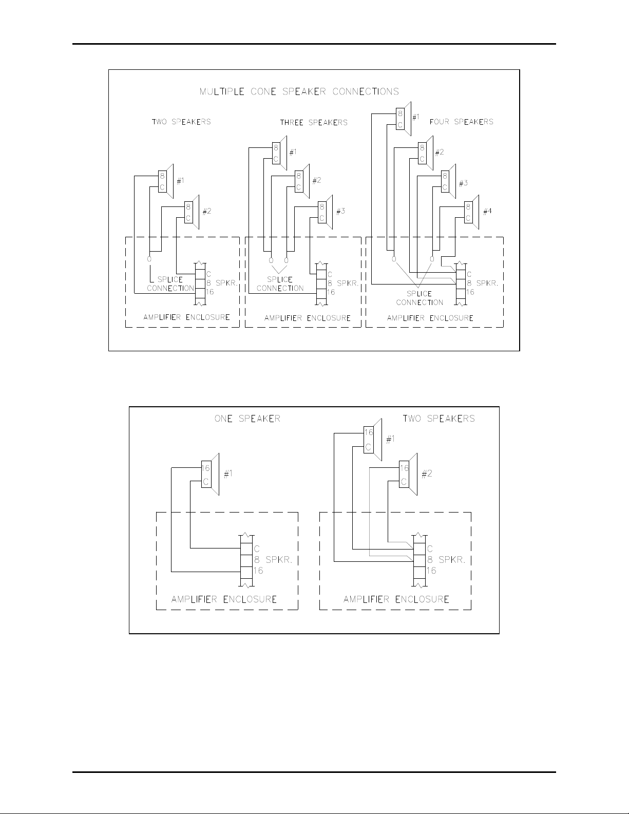
If two 16-ohm speakers are to be operated from one amplifier, wire them in parallel and connect them to
the 8-ohm output.
In many applications, multiple cone-type or smaller horn-type speakers may be driven from one GAITronics Page/Party
®
amplifier. Figure 1 illustrates how two, three, or four 8-ohm units may be wired to
one amplifier. Figure 2 illustrates 16-ohm unit connections to one amplifier.
Do not connect loudspeakers in series when installing them in critical broadcast areas as the failure of one
speaker renders the remaining speakers inoperable. Parallel speaker wiring installations are preferred
ensuring that if a single speaker fails, the remaining speakers connected to that amplifier will continue to
operate.
f:\standard ioms - current release\42004 instr. man uals\42004-135h.doc
03/15
Page 3
Pub. 42004-135H
Speaker/Horn Installation for GAI-Tronics Communications Systems Page 3 of 8
Figure 1. Cone Speaker Connections
Figure 2. 16-ohm Speaker Connections
f:\standard ioms - current release\42004 instr. man uals\42004-135h.doc
03/15
Page 4

Pub. 42004-135H
Speaker/Horn Installation for GAI-Tronics Communications Systems Page 4 of 8
Distributed Amplifier Systems
GAI-Tronics Page/Party® and SmartSeries systems do not use speakers with line matching transformers.
The voltage on the wiring between the speaker(s) and the associated amplifiers is less than 15 V
, which
RMS
qualifies as National Electrical Code Class II wiring. Therefore, conduit is not required except for
physical protection. Cable distance should be as short as possible to reduce power loss. GAI-Tronics
recommends that the cable distance between a speaker and its associated amplifier not exceed 30 feet
(9.14 meters).
Indoor Cone Spea kers
Depending on the amplifier and speaker combination used, an indoor cone speaker’s volume control and
speaker can be damaged due to the application of excessive power. In order to minimize the possibility of
such an occurrence, use the following set-up procedure:
1. Turn the amplifier
the speaker
volume control (if applicable) to its maximum output position.
volume control to its lowest output lev el be fo re applying power to the system. Set
2. Measure the dc resistance of the speaker using a volt-ohm meter. Read the wattage rating of the
speaker and perform the following calculation:
Multiply the resistance of the speaker (Rspkr) by the speaker’s wattage rating (Wspkr), and find the
square root.
This number is the voltage (rms) limit from the amplifier to the speaker that should not be exceeded.
VrmsWspkrRspkr limit
3. Apply power to the unit, and connect a 1 kHz @ 1.5 Vrms signal into the amplifier via the page line
with a voltmeter across the speaker terminals. Adjust the amplifier
volume control until the voltage
limit is reached.
4. The speaker volume control may then be used to reduce the speaker level to the proper liste ning level
as changing conditions warrant.
OTE: Using this procedure does not guarantee that damage will not occur to the volume control or
N
speaker since there are other variables, but it does minimize the possibility.
Central Amplifier Systems
Central or power amplifier systems are generally designed to use a driver with a 70 or 100 volt, line
matching transformer. The speaker’s power level is determined by the tap settings on the transformer.
Use of these transformers allows the speakers to be placed at long distances from the amplifier without
significant power loss (see Tab le 1 below).
The number of speakers connected to a central amplifier system is limited by the power available from
the central amplifier. The sum of the speaker power settings must not exceed the total available from the
amplifier. For example, a 250-watt central amplifier can drive 30 speakers tapped at 7.5 watts.
Table 1 illustrates the correlation between the wire size and the distance that speakers with integral
drivers or horns with separate drivers can be placed from a central amplifier.
f:\standard ioms - current release\42004 instr. man uals\42004-135h.doc
03/15
Page 5

Pub. 42004-135H
Speaker/Horn Installation for GAI-Tronics Communications Systems Page 5 of 8
Table 1.
Typical Central Amplifier @ 20% Loss
Wire size 70.7 V Line
No. 18 AWG (0.82 mm2) 6250 feet (1903 m)
No. 16 AWG (1.31 mm2) 9900 feet (3017 m)
No. 14 AWG (2.08 mm2) 15,800 feet (4816 m)
Table 2.
Mounting Assembly Application Chart
Speaker Drivers
Speaker Horns 13310 (Note 1 ) 13314
13302-002 415A 411A
13304-002 415A 411A
13305-101 413A 413A
13306-101 (See Note 2) 415A 411A
13340 415A 411A
HP15-8 Has integral driver—use 412B
13328-001 Has integral driver—use 412-002
NOTES:
1. When using any Division 1 speaker or driver unit, the speaker mounting assembly may be used only
to support and orient the speaker. Division 1 fittings must be used for electrical connections.
2. When mounting the GAI-Tronics part # 13306-101 speaker horn in an upright orientation, the 411A
mounting assembly can be used with either the 13310 or 13314 Driver. See Figure 5.
f:\standard ioms - current release\42004 instr. man uals\42004-135h.doc
03/15
Page 6

Pub. 42004-135H
Speaker/Horn Installation for GAI-Tronics Communications Systems Page 6 of 8
Figure 3. Wall Mounting Bracket
f:\standard ioms - current release\42004 instr. man uals\42004-135h.doc
03/15
Page 7

Pub. 42004-135H
Speaker/Horn Installation for GAI-Tronics Communications Systems Page 7 of 8
f:\standard ioms - current release\42004 instr. man uals\42004-135h.doc
03/15
Figure 4.
Page 8

Pub. 42004-135H
Speaker/Horn Installation for GAI-Tronics Communications Systems Page 8 of 8
f:\standard ioms - current release\42004 instr. man uals\42004-135h.doc
03/15
Figure 5.
 Loading...