

Page 1

Pub. 42003-188A
GAI-TRONICS® CORPORATION
A HUBBELL COMPANY
Pole Cap Assembly Kit
Model RFP7783-003
Confidentiality Notice
This manua l is provide d sole ly as an operatio nal, installation, and ma inte nance guide and conta ins
sensitive business and t e chnic al infor ma tion w hich is conf ident ial and pr op riet ary to GAI-Tro nics.
GAI-Tronics retains all intellectual property and other rights in or to the information contained herein,
and such information may only be used in connection with the operation of your GAI-Tronics product or
system. This manu al may not be dis clos e d in any form, in whole or in pa rt, direct ly or i ndir ectly, to a ny
third pa r ty.
General Information
The Model RFP7783-003 Pole Cap Assembly Kit provides a platform for securing a solar panel array,
cellular antenna, and external ringer onto the top of a 4.0-inch O.D. steel pole. The assembly is designed
to seal the interior of the pole against moisture. The kit includes the following components:
Qty Description
1 Pole cap assembly with adjustable bracket
2 Wa ter-tight hub (for solar panel and external ringer f e ed-through)
1 Siemens solar panel, 20 watt
Installation
Refer to Figure 1 while completing the following steps to install the Pole Cap Assembly.
Tools and Equip ment Required
• Model RFP7791-001 External Ringer Kit with Stainless Steel Ringer Bracket
• Model RFP7783-002 Antenna Kit
• Integrity Loop Cable Assembly (Part No. 61504-101)
• Protractor
• Compass
• Specialized tamper-resistant Allen wrench
• 2/C AWG 20 wire, 15 feet (minimum jacket O.D. = 0.25 in.)
GAI-Tronics Corporation P.O. Box 1060, Readi ng, PA 19607-1060 USA
610-777-1374 800-492-1212 Fax: 610-796-5954
ISIT WWW.GAI-TRONICS.COM FOR PRODUCT LITERATURE AND MANUALS
V
Page 2
Pub. 42003-188A
M
ODEL RFP7783-003 POLE CAP ASSEMBLY KIT Page: 2 of 3
Pole Cap Assembly Instructions
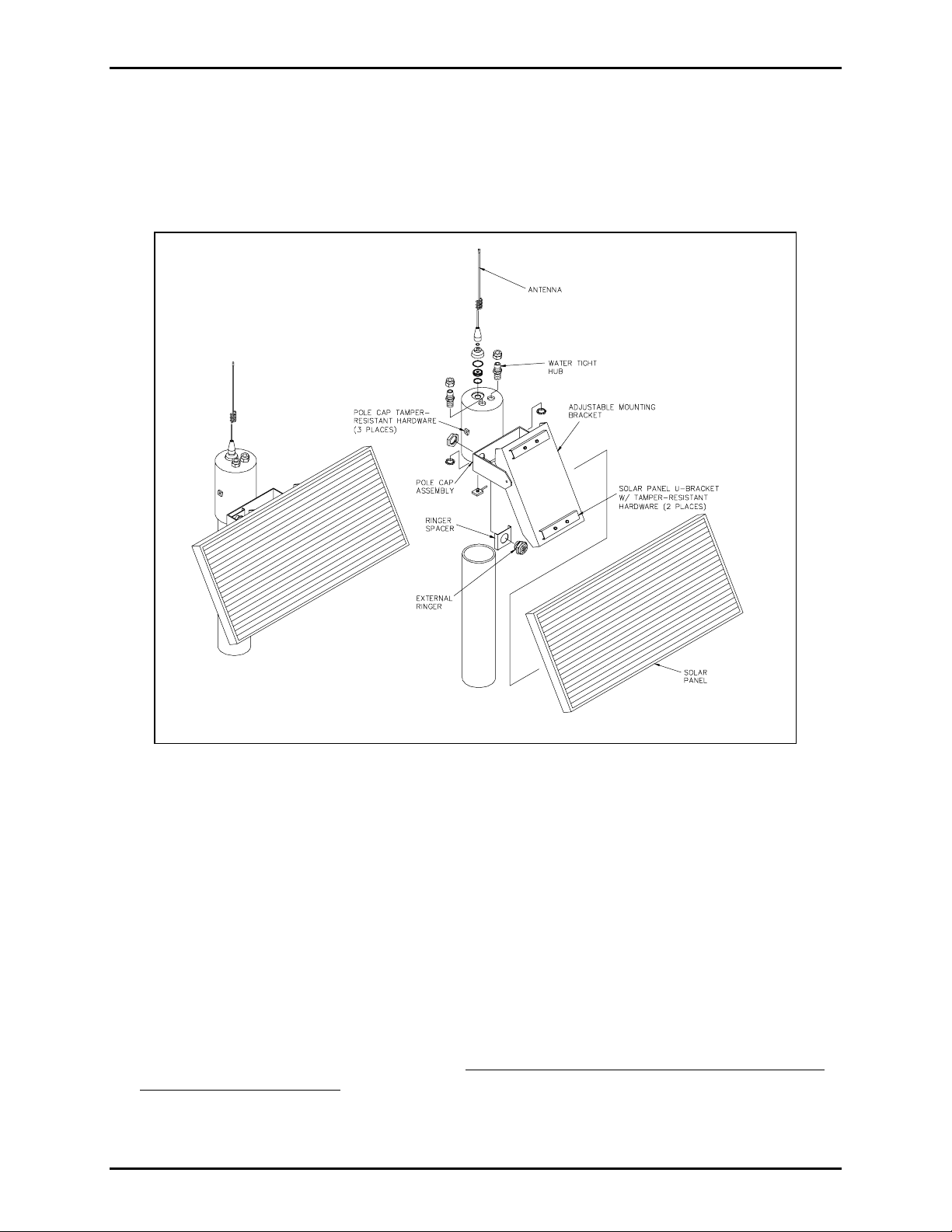
The pole cap housing contains three holes: a 0.75-inch hole for the antenna coaxial cable, a 0.875-inch
hole for the external ringer cable, and another 0.875-inch hole for the solar panel cable entry. The
attached adjustable mounting bracket is used to mount the Siemens solar panel. Refer to Figure 1 below
whi le completing the steps to instal l the pole ca p a sse m bly onto the po le.
Figure 1. Pole Cap Assembly with Exploded View
Install the antenna, external ringer, and solar panel to the pole cap housing while on the ground:
1. Assemble cellular antenna onto pole cap housing through the 0.75-inch hole using installation
directions and hardware supplied with Model RFP7783-002 Antenna Kit.
2. Secure the Siemens solar panel onto the pole cap housing’s adjustable mounting bracket using two U-
bracket with the tamper-resistant hardware to clamp down on the inside lip of the solar panel. See
Figure 1.
3. Secure Model RFP7791-001 External Ringer onto the pole cap housing’s horizontal bracket
(1.14-inch (32mm) through hole) using the supplied ringer spacer bracket and ringer nut.
4. Double up the length of the integrity loop wire and tape or apply heat shrink tubing to join the solar
panel cable to the closed end of integrity loop. Be sure to install integrity loop right up to the potted
modu le on r ear of solar panel. Feed the combined solar panel cable/integrity loop wire through one
of the 0.875-inch water-tight hubs. Hand tighten the locking hub to seal.
\\s_eng\gtc proddoc s \st andard iom s - current release\42003 kit manuals \ 42003-188a.doc
12/00
Page 3

Pub. 42003-188A
M
ODEL RFP7783-003 POLE CAP ASSEMBLY KIT Page: 3 of 3
5. Feed external ringer cable through the other 0.875-inch hole. Use a wrench to tighten the locking hub
to seal.
6. At the top of the pole: Feed solar panel cable/integrity loop wire , external ringer cable, and the
antenna RG-58 coax cable down through top of pole. Seat pole cap assembly onto pole top.
7. Orient the pole cap assembly for a southern exposure in the northern hemisphere or a northern
exposure in the southern hemisphere as determined by the compass bearing. Secure the assembly by
using the 3 installed tamper-resistant Allen socket-head screws.
8. Adjust th e s olar panel el e vation. S et the pa nel in accordance with the foll owin g chart usin g
installation site latitude and corresponding tilt angles:
Latitude of
Instal latio n Site
Tilt Angle
0°to 15° 15°
15°to 25° Angle is same as latitude
25°to 30° Latitude plus 5°
30°to 35° Latitude plus 10°
35°to 40° Latitude plus 15°
Plus 40° Latitude plus 20°
9. Secure solar panel at the proper angle using tamper-resistant hardware supplied.
\\s_eng\gtc proddoc s \st andard iom s - current release\42003 kit manuals \ 42003-188a.doc
12/00
Page 4

Warranty
Equipment. GAI-Tronics warrants for a period of one (1) year from the date of shipment, that any
GAI-Tronics equipment supplied hereunder shall be free of defects in material and workmanship, shall
comply with the then-current product specifications and product literature, and if applicable, shall be fit
for the purpose specified in the agreed-upon quotation or proposal document. If (a) Seller’s goods prove
to be defective in workmanship and/or material under normal and proper usage, or unfit for the purpose
specified and agreed upon, and (b) Buyer’s claim is made within the warranty period set forth above,
Buyer may return such goods to GAI-Tronics’ nearest depot repair facility, freight prepaid, at which time
they will be repaired or replaced, at Seller’s option, without charge to Buyer. Repair or replacement shall
be Buyer’s sole and exclusive remedy. The warranty period on any repaired or replacement equipment
shall be the greater of the ninety (90) day repair warranty or one (1) year from the date the original
equipment was shipped. In no event shall GAI-Tronics warranty obligations with respect to equipment
exceed 100% of the total cost of the equipment supplied hereunder. Buyer may also be entitled to the
manufacturer’s warranty on any third-party goods supplied by GAI-Tronics hereunder. The applicability
of any such third-party warranty will be determined by GAI-Tronics.
Services. Any services GAI-Tronics provides hereunder, whether directly or through subcontractors,
shall be performed in accordance with the standard of care with which such services are normally
provided in the industry. If the services fail to meet the applicable industry standard, GAI-Tronics will
re-perform such services at no cost to buyer to correct said deficiency to Company's satisfaction provided
any and all issues are identified prior to the demobilization of the Contractor’s personnel from the work
site. Re-performance of services shall be Buyer’s sole and exclusive remedy, and in no event shall GAITronics warranty obligations with respect to services exceed 100% of the total cost of the services
provided hereunder.
Warranty Periods. Every claim by Buyer alleging a defect in the goods and/or services provided
hereunder shall be deemed waived unless such claim is made in writing within the applicable warranty
periods as set forth above. Provided, however, that if the defect complained of is latent and not
discoverable within the above warranty periods, every claim arising on account of such latent defect shall
be deemed waived unless it is made in writing within a reasonable time after such latent defect is or
should have been discovered by Buyer.
Limitations / Exclusions. The warranties herein shall not apply to, and GAI-Tronics shall not be
responsible for, any damage to the goods or failure of the services supplied hereunder, to the extent
caused by Buyer’s neglect, failure to follow operational and maintenance procedures provided with the
equipment, or the use of technicians not specifically authorized by GAI-Tronics to maintain or service the
equipment. THE WARRANTIES AND REMEDIES CONTAINED HEREIN ARE IN LIEU OF AND
EXCLUDE ALL OTHER WARRANTIES AND REMEDIES, WHETHER EXPRESS OR IMPLIED BY
OPERATION OF LAW OR OTHERWISE, INCLUDING ANY WARRANTIES OF
MERCHANTABILITY OR FITNESS FOR A PARTICULAR PURPOSE.
Return Policy
If the equipment requires service, contact your Regional Service Center for a return authorization number
(RA#). Equipment should be shipped prepaid to GAI-Tronics with a return authorization number and a
purchase order number. If the equipment is under warranty, repairs or a replacement will be made in
accordance with the warranty policy set forth above. Please include a written explanation of all defects to
assist our technicians in their troubleshooting efforts.
Call 800-492-1212 (inside the USA) or 610-777-1374 (outside the USA) for help identifying the
Regional Service Center closest to you.
(Rev. 10/06)
 Loading...