

Page 1
480
en
Installation Instructions
please keep
nl
Installatievoorschrift
a.u.b. bewaren
1
de
fr
it
es
pt
Einbauanleitung
bitte aufbewahren
Notice de montage
veuillez conserver
Istruzioni di Montaggio
Siete pregati di conservarle
Instrucciones de Montaje
por favor, guardar
Instruçoes de Montagem
por favor, guardar
min.60
min.30
tr
sv
no
da
fi
Montaj talimatları
Lütfen saklayınız
Monteringsanvisning
förvara p säkert ställe
å
Monteringsanvisning
oppbevar informasjonen
Montagevejledning
b r opbevares
ø
Asennusohjeet
säilytä huolella
min.30
5
2
150
A
3
85
62,5
710
1
/2” ISO 228
1
/2” ISO 7-1 Rc
oder
44,5
55
Page 2
4
2
a
85
710
60
3a
Page 3
4
5
a
4b
5
5
6
6a
7
Ø max.
12,4
Page 4
8
9
9a
9b
9c
Page 5
10
11
12
Page 6

en
Ú Installation instructions
Instructions for the installer
All operations relating to installation, regulation and
conversion to other types of gas must be carried out by
an authorised installation engineer, respecting
applicable regulations, standards and the specifications
of the gas and electricity providers.
Before you begin, turn off the appliance' s electricity
and gas supply.
You are recommended to contact the Technical
Assistance Service to convert to another type of gas.
This appliance has been designed for home use only, not
for commercial or professional use. This appliance cannot
be installed on yachts or in caravans. The warranty will
only be valid if the appliance is used for the purpose for
which it was designed.
Before connecting the appliance to the supply, check that
it is prepared for the type of gas in question (see table I).
Our hobs leave the factory set for the gas type indicated
on the characteristics plate.
This appliance must be installed in a place with the
proper level of ventilation. The gases produced during
combustion must be released to the outside.
Check the size of the hob and the size of the opening to
be made on the kitchen unit.
The work surface must be level and horizontal. The
stability of the work surface must still be guaranteed after
the cut-out has been made. The work surface must be
sealed with the wall to protect against damp.
If it is to be installed over an oven, you must check that
the oven is suffiently well ventilated and check the
dimensions as given in the installation manual.
The panelling on the work surface in the immediate
vicinity of the hob must be made of non-flammable
material. Both stratified coatings and the adhesive used
to fix them in place must be heat resistant. Otherwise,
they may be damaged.
Electric wiring must not come into contact with hot areas.
The mains supply cable must be fixed to the kitchen unit
to prevent it from coming into contact with hot parts on
the oven or hob.
Appliances with electric components must be earthed.
Handle the appliance with care throughout the entire
installation process. Avoid knocking the appliance.
This appliance shall be installed in accordance with the
regulations in force and only used in a well ventilated
location. Read the instructions before installing or
using this appliance.
SHOULD THE RELEVANT CONDITIONS NOT BE
PROPERLY SATISFIED, THE INSTALLER, AND NOT
THE MANUFACTURER, SHALL HELD LIABLE.
Installing the hob in the kitchen unit
The positioning of a hob in a kitchen unit is Class 3
according to the standard for gas appliances EN 30-1-1.
The wood fibres used in the manufacture of kitchen work
surfaces are liable to swell when they come into contact
with moisture. You are recommended, therefore, to coat
cut edges with a special adhesive to protect them from
steam or condensed water which could deposit beneath
the work surface on the kitchen unit.
The fixtures and the watertight seal (lower edge of the
hob) come factory-fitted. Do not under any circumstances
remove them. The seal keeps the entire work surface
watertight and prevents leakage.
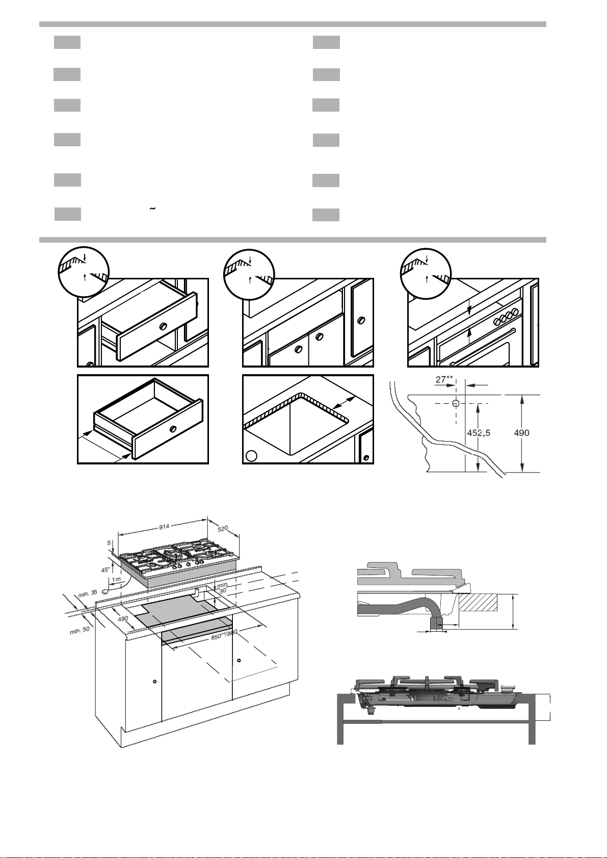
It is necessary place a separator of non-flammable
material e.g. plywood or metal at a distance of 10 mm.
from the bottom of the hob to prevent access to the lower
part of the hob. Fig. 2-2a.
In the event that a drawer is located beneath
please make sure that the drawer contains no
heat-sensitive or easily combustible objects, such as
shoe polish. Use a heat-resistant utility drawerspray cans or
only.
If the cooking hob is to be installed above an oven, check
that the oven is fitted with power ventilation, and check the
dimensions according to the assembly manual.
Once the hob is fitted you should turn the clipand tighten
the screw as shown in Fig. 4. For disassembly, unscrew
the clip and proceed in the reverse manner.
the appliance,
A- Normal installation method
1- Minimum Distances (mm). Cut a hole of the necessary
size in the work surface, Fig. 2.
Centre the hob in the hole on the work surface.
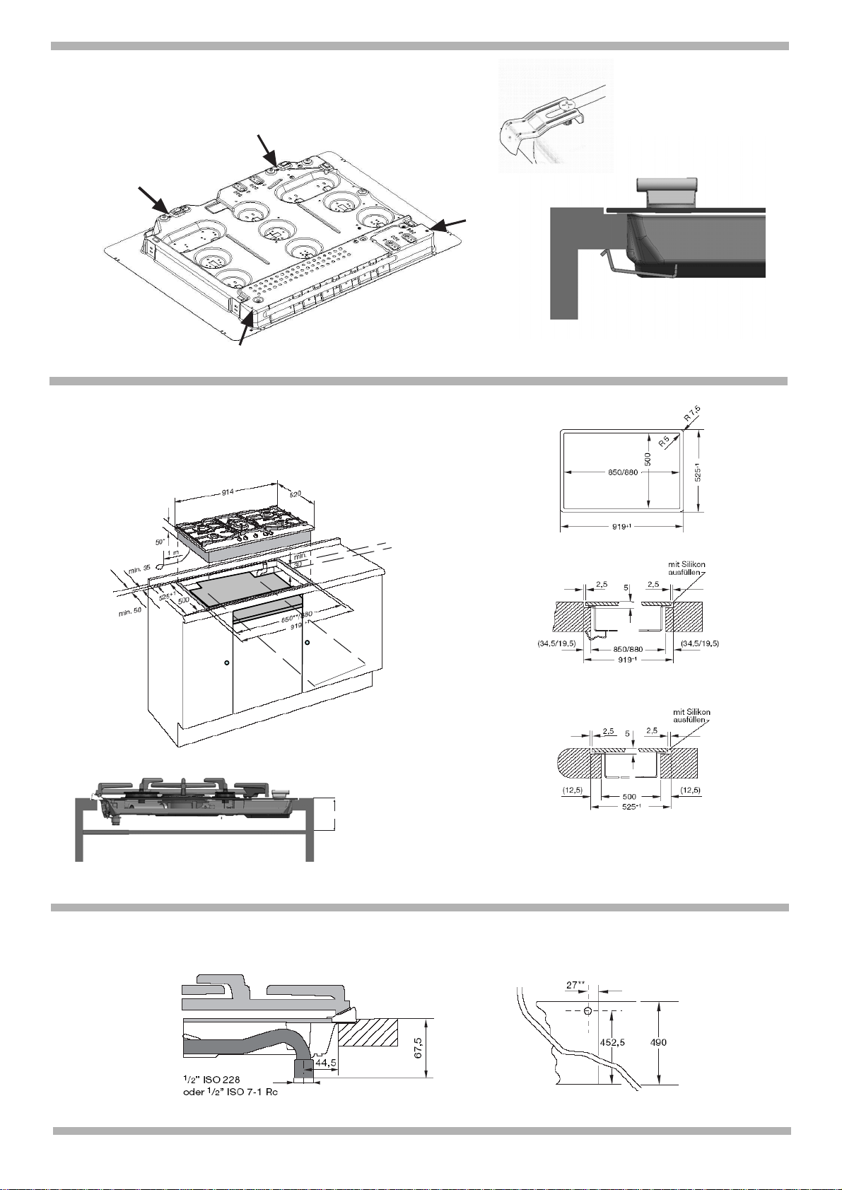
B- Flush installation method
Important note:
All cut-outs in the work surface are to be carried out at
a specialist workshop.
The cut must be clean and precise, since the cut edge
is visible on the surface. The stability of furniture being
worked on must be ensured following the cut-outs.
Use special heat and water-resistant work surface (e.g.
natural stone or tiled work surfaces).
See the diagram for the cutting dimensions. Fig. 2a.
The units into which the cooker is fitted must be heatresistant up to 90ºC.
On tiled worktops:
If necessary, raise the height of the surfaces by fitting heat
and water-resistant strips all the way round. Fig. 5
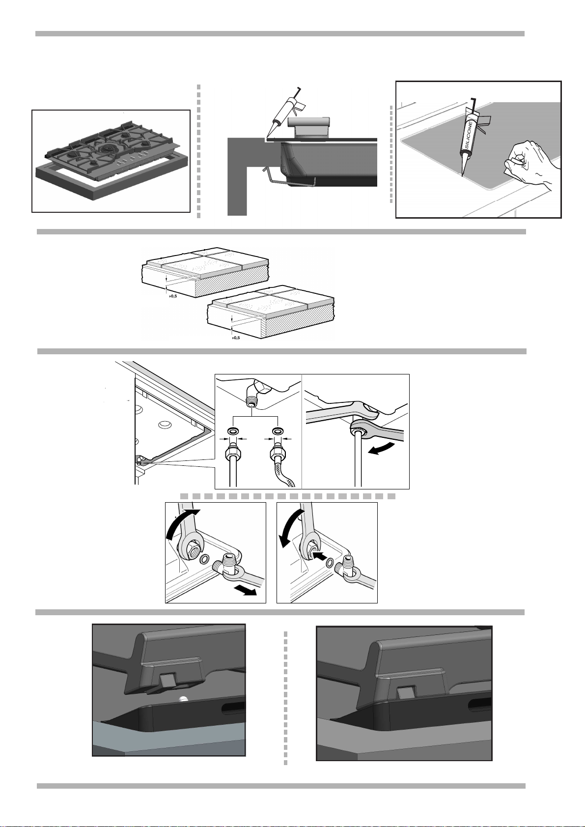
Place the hob horizontally into the cut-out and align it,
ensuring that the join is even on all sides, Fig. 4a. The hob
should be positioned just below the work surface.
1- Check the function and location of the appliances.
2- Fill in the gap between the worktop and the ceramic hob
using a suitable commercial silicone bonding agent in a
colour of your choice. Fig. 4b.
Caution. Use of unsuitable silicone bonding agents on
natural stone worktops can cause permanent
discoloration.
Please observe the manufacturer´s instructions for use.
Apply the silicone bonding agent in the joints.
Before the silicone bonding agent stars to form a skin,
moisten a blade or your finger with a soapy solution and
smooth it over.
The hob should only be used once the silicone bonding
agent has hardened.
Hotplates connection
3- The end of the input collector on gas hobs comes with a
1/2” (20.955 mm) threaded L-tube, Fig. 3a. This caters for:
Rigid connection.
Connection to a flexible metal tube (L min. 1 m - max. 3 m):
If this method is used, avoid both contact between this
tube and moving parts on the housing (e.g. drawers) and
passing the tube through spaces liable to get blocked.
In either of the cases, do not move or twist the L-tube from
its factory-set position, Fig. 6.
To use this appliance in France, it is necessary to
remove the L-tube mounted in the factory and assemble
the one supplied in the accessory bag. Fig. 6a. Do not
forget to insert the seal. If, for some reason, the L-tube
should be twisted, it is necessary to make sure that this
area is properly sealed. Make sure that all connections
performed are free of leakage.
The manufacturer does not accept any liability for leakage
on connections performed by the installer or if the L-tube is
moved or twisted.
Page 7

4- Check the voltage and total power on the
characteristics plate. The appliance must be EARTHED.
Make sure that connection has been performed in
accordance with legal regulations in force for the country
in question and complies fully with the conditions laid
down by the local electricity company.
In order to meet normal safety standards, the installer must
supply an all-pole circuit breaker with a contact aperture of
at least 3 mm. This is not necessary when connection is
made via a socket, so long as this is accessible to the user.
Appliances equipped with plugs should only be connected
to sockets which are duly earthed.
The appliance is type "Y". This means that the input supply
cable cannot be changed by the user. Only the brand's
service technicians are qualified to replace this cable. Use
the right cable type and section.
Do not tamper inside the appliance. If necessary, call our
Service Centre.
Hobs with control knobs are supplied with a plugged or
unplugged power cable.
TYPES OF CABLE
Power cable: Hob:
All gas 3 x 0.5 mm
2
5- In order to complete the installation process, you must
place the diffusers and the tops of the burners on their
corresponding burners. Also you must place the grids
correctly on their supporting elements. Fig. 7.
Changing the type of gas
All operations relating to installation, regulation and
conversion to other types of gas must be carried out by
an authorised installation engineer, respecting
applicable regulations, standards and the specifications
of the gas and electricity providers.
Before you begin, turn off the appliance' s electricity
and gas supply.
You are recommended to contact the Technical
Assistance Service to convert to another type of gas.
Before connecting up the appliance to the installation, first
check that it has been adjusted for the type of gas with
which it is to be supplied. Our cooking hobs leave the
factory designed to function with the type of gas that is
indicated on the specifications plate.
Provided that national laws so permit, this cooking hob
may be adapted to function with other types of gas. To do
so, all the following steps should be carried out:
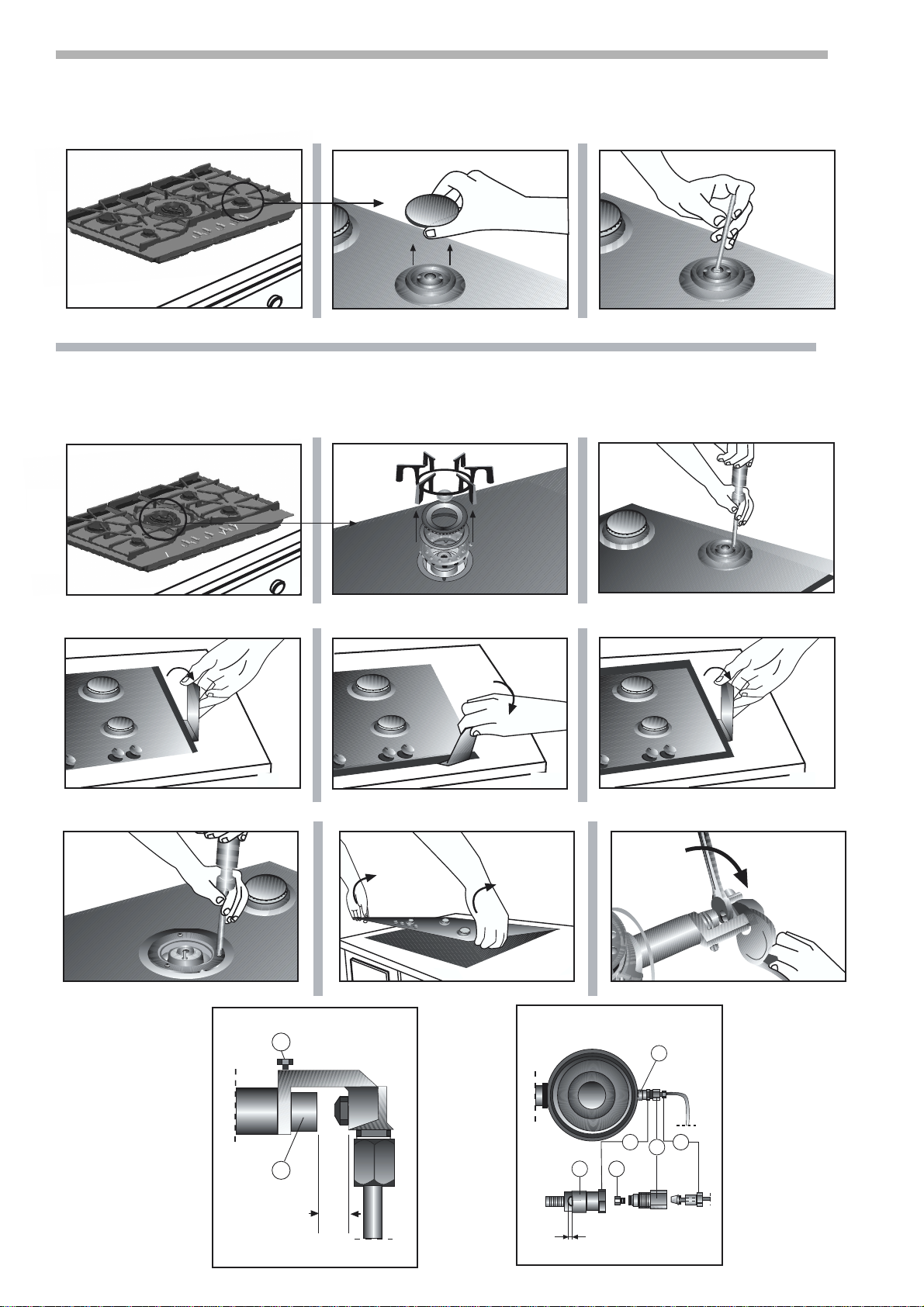
A ) Change of rapid, semi-rapid and aux iliary burner tips
(see table II).
1- R emove the pan supports, the cover and the main body
of the burner.
2- Change the burner tip using the spanner provided by
our technical services department (code 424699) taking
special care to ensure that the burner tip does not fall
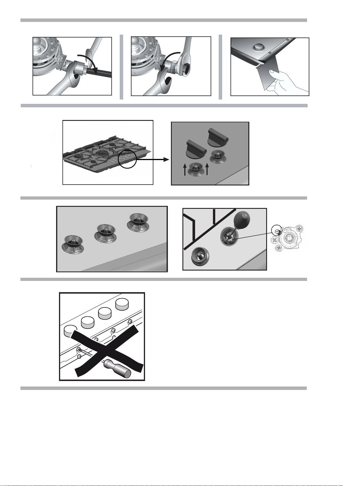
when you remove it from the burner or replace it.
Ensure that it is completely tightened in order to guarantee
the seal. Fig. 8.
W ith these burners the air does not have to be adjusted.
B) Changing the tips on the upper large double flame
flame burner.
The glass panel and the frame are fixed to the rest of the
cooking hob by means of clips. The following steps must
be taken to remove both the glass panel and frames:
1- Remove all the burners, caps, diffusers, etc. Fig. 9a.
2- Loosen the two screws on the rapid, semi-rapid and
auxiliary burners. Fig. 9b.
3- Loosen the three screws on the large double flame
burner Fig. 9c.
4- Use the disassembly lever 483196 available from o
ur
technical assistance service. To release the front clips,
apply the lever in the area shown in figures X1, X2, X3,
depending on the hob model.
Never use the lever on glass edges which have no trim
or frame!
Before putting the glass back, check that the watertight
seals are properly adjusted.
5- To release the rear clips, carefully raise the entire glass
unit along with the frame, as in Fig. X4.
6- Changing the outer flame burner tip.
Take out the main burner tip turning it to the left with a 10 mm
spanner. At the same time, hold the burner tip casing in
the opposite direction with a 13 mm spanner. Fig. K.
Screw in the new main burner tip, pushing the burner tip
casing in the opposite direction with a 13 mm spanner.
Loosen the holding screw Fig. L1 and set the regulating
bushing of the air flow to the value indicated in the burner
tip table. -Z Tighten the locking screw.
7- Changing the inner flame burner tip.
Using an 8 mm spanner, unscrew the connector Fig. M3
from the threaded component Fig. M2. To do this, hold
the threaded component firmly in the opposite direction
using a 12 mm spanner. See Fig. N.
Then, using a 12 mm spanner, unscrew the threaded
component Fig. M2 from the component Fig. M1, holding
the latter firmly in the opposite direction with a 12 mm
spanner. See Fig. O.
Unscrew the burner tip Fig. M4 from component Fig. M2
and replace it with the appropriate burner tip as indicated
in the burner tip table, and adjust the regulating bushing
of the air flow M5 in line with the value indicated in the
burner tip table. -Y If the appliance is not firmly fixed or the clipping system
*
is too rigid, it may cause the entire appliance to lift up.
In this case follow this procedure:
1- Loosen the fixing clips of the appliance to the kitchen
unit.
2- Loosen the main gas connection and take the appliance
out of its seating.
3- Apply the disassembly lever 483196 as shown in
Fig. W .
C) Adjusting the reduced consumption of taps and
burners and of the cooking hob
1- Set the taps to minimum.
2- Remove the control knobs from the taps. Fig. 10
3- It has a flexible rubber seal. Simply apply pressure with
the tip of the screwdriver to release the thread toward
the tap's adjusting screw. Fig. 11.
Do not remove the disc seal.
4- Adjust the By-pass screw.
Depending on the type of gas you wish to change the
appliance to, you must perform one of the following
processes, marked A, B, C and D:
A) The By-pass screws must be fully done up.
B) The By-pass screws must be loosened until the
correct flame is achieved.
C) The By-pass screws that are fitted on the appliance
must be substituted for the ones that are supplied in the
transformation kit.
D) In this case, you must not alter the By-pass screws.
In all cases, after the gas changeover has been carried
out, make sure that the burner flames are correct by
ensuring that when you go from the maximum setting to
the minimum they do not go out and there is no flame
backdraught.
Consult Table III in order to find out which case applies
to you: A, B, C or D.
5- It is important that all the reinforcement rings are in
place in order to ensure that the electrics are sealed to
protect against any liquids that may spill from the hob.
6- Replace the control knobs on the taps.
Do not dismantle the tap shaft, Fig. 12: In the event of a
malfunction, change the whole tap.
D) Place the sticker indicating that the appliance's gas
supply has been changed next to the specifications plate.
Page 8

de
Þ Notice de montage
Anleitungen für den Installateur
Alle Installations-, Regelungs- und
Umstellungsarbeiten auf eine andere Gasart müssen
vom einem autorisierten Fachmann und unter
Beachtung der jeweils anwendbaren Regelungen und
gesetzlichen Vorgaben sowie der Vorschriften der
örtlichen Strom- und Gasversorger vorgenommen
werden.
Für Umstellungsarbeiten auf eine andere Gasart
empfehlen wir, den Kundendienst zu rufen.
Stellen Sie vor der Durchführung
die Strom- und Gaszufuhr ab.
Dieses Gerät wurde ausschließlich für die Verwendung in
Privathaushalten entworfen; eine kommerzielle oder
gewerbliche Nutzung ist nicht gestattet. Dieses Gerät darf
nicht auf Jachten oder in Wohnwagen eingebaut werden.
Die Garantie gilt nur dann, wenn das Gerät
für seinen vorgesehenen Zweck genutzt wird.
Vor dem Anschluss des Geräts an die Installation muss
sichergestellt werden, dass das Gerät für die zugeleitete
Gasart geeignet ist (siehe Tabelle I). Unsere Kochfelder
sind werksseitig für den Betrieb mit dem auf dem
Typenschild angegebenen Gastyp eingestellt. Der Ort,
an dem das Gerät installiert werden soll, muss über die
vorschriftsmäßige Belüftung verfügen. Daher müssen
die Verbrennungsgase ins Freie ausgeleitet werden. Die
Abmessungen des Kochfelds sowie die Abmessungen
der Öffnung, die im Möbel angefertigt werden muss,
überprüfen. Die Arbeitsplatte muss eben und horizontal
sein. Die Stabilität muss garantiert sein, wenn der Schnitt
einmal durchgeführt wurde. Die Arbeitsplatte muss zur
Wand hin hermetisch versiegelt sein, um dem Eindringen
von Feuchtigkeit vorzubeugen.
Für die Installation auf einem Herd muss nachgeprüft
werden, ob dieser eine verstärkte Abluft besitzt und man
muss ebenfalls die Abmessungen überprüfen, die laut
dem Montagehandbuch angegeben sind. Die Platten
auf der Arbeitsfläche in der direkten Umgebung des
Kochfelds müssen aus nicht brennbarem Material
bestehen. Sowohl die Schichtwerkstoffe als auch
der Bindeleim müssen hitzebeständig sein, damit kein
Verschleiß auftritt. Die elektrischen Leitungen dürfen
keine Berührung zu den Hitzebereichen haben. Die
Stromnetzleitung muss am Küchenmöbel befestigt
werden, damit es keine heißen Teile des Ofens oder
des Kochfelds berühren kann. Geräte mit elektrischen
Bauteilen müssen vorschriftsgemäß mit der Erdableitung
verbunden werden. Gehen Sie bitte, während des
gesamten Einbauprozesses mit dem Gerät sorgfältig um.
Nicht auf das Gerät einhämmern. Dieses Gerät muss
gemäß der geltenden Richtlinien und ausschließlich an
einem gut belüfteten Ort eingebaut werden. Lesen Sie
vor dem Einbau und vor dem Gebrauch dieses Gerätes
die Bedienungsanleitung.
WERDEN DIE DIESBEZÜGLICHEN BESTIMMUNGEN
NICHT EINGEHALTEN, LIEGT DIE HAFTUNG BEIM
INSTALLATEUR, UND DER HERSTELLER IST VON
DER HAFTUNG BEFREIT.
Die Montage des Kochfeldes in dem
Möbelstück
Die Möglichkeit der Lage des Kochfeldes, entspricht der
Klasse 3 gemäss der Norm für Gasgeräte EN 30-1-1.
Die Holzfaserplatten, die für die Herstellung des
Möbelstückes
quellen bei Kontakt mit Feuchtigkeit ziemlich schnell auf.
Daher sollten die Schnittflächen mit einem Spezialleim
behandelt werden,
Kondenswasser, das sich unter der Arbeitsplatte des
Küchenmöbels bilden
für das Kochfeld verwendet werden,
um diese Flächen vor Dampf und vor
kann, zu schützen. Die Schellen
jeglicher Arbeiten
ausschließlich
und die Dichtungsringe (am inneren Rand des Kochfeldes)
werden in schon in der Fabrik angebracht.
Bauen Sie eine Trennplatte aus nicht entflammbarem
Material, z.B. Sperrholz oder Metall, im Abstand von
10 mm von der Unterseite der Kochmulde ein, um zu
verhindern, dass die Kochmulde von unten berührt werden
kann. Abb. 2-2a.
Wenn unter dem Gerät eine Schublade eingebaut wird,
stellen Sie sicher, dass sich in der Schublade keine
hitzeempfindlichen oder leicht entflammbaren
Gegenstände wie Spraydosen oder Schuhcreme befinden.
Verwenden Sie nur hitzebeständige Schubladen.
Man muss, wenn das Kochfeld einmal eingebaut ist, die
Schellen drehen und mit Kraft anziehen, so wie es in
Abbildung 4 angezeigt ist.
Wenn Ihre Demontage genau sein soll, dann müssen Sie
die Schellen entfernen und in der Umgekehrten Weise
fortfahren.
A. Verfahrensweise beim normalen Einbau.
1- Mindestabstände in (mm). In der Arbeitsplatte einen
Ausschnitt mit den erforderlichen Abmessungen
ausführen. Abb. 2.
Das Kochfeld in seiner Einbauöffnung im Küchenmöbel
zentrieren.
B. Verfahrensweise des bündigen Einbaus
Wichtiger Hinweis:
Alle Ausschnittarbeiten an der Arbeitsplatte müssen in
einem Spezialgeschäft durchgeführt werden.
Die Schnittstellen müssen sauber und genau sein, da
man die Kanten an der Oberfläche sieht. Die Stabilität
der Möbel muss auch nach den Schnittarbeiten
garantiert sein.
Es dürfen einzig und allein Spezialarbeitsplatten verwendet
werden, die gegen Temperatur und Wasser resistent sind
(z.B. Naturstein oder geflieste Arbeitsplatten).
Schnittmasse, siehe Abb. 2a.
Die Einbaumöbel müssen gegen Temperaturen bis 90 ºC
beständig sein.
Die gefliesten Arbeitsplatten:
wenn es notwendig sein sollte, die Auflageflächen mit
Temperatur-und Wasserwiderstandsfähigen Leisten
anheben Abb. 5.
Setzen Sie das Kochfeld horizontal in das Loch und achten
Sie darauf, dass um das Gerät eine gleichmässige Nut
bleibt, Abb. 4a. Das Kochfeld muss leicht unter der
Arbeitsoberfläche bleiben.
1-Überprüfen Sie die Funktion und die Position der Geräte.
2-Füllen Sie Nut zwischen der Arbeitsplatte und der
Keramikplatte mit herkömmlichen Silikonleim, entsprechend
der gewünschten Farbe aus. Abb. 4b. Achtung: Wenn
man bei den Arbeitsplatten aus Naturstein ungeeignetes
Silikon verwendet, können Verfärbungen entstehen, die
dann nicht entfernt werden können.
Füllen Sie den Silikonleim in die Nut ein. Streichen Sie den
Silikonleim mit einem Abstreichmesser oder mit dem mit
Seife angefeuchteten Finger glatt, bevor sich eine Schicht
bildet.
Benutzen Sie das Gerät, wenn der Silikonleim getrocknet ist.
Anschluss des Kochfeldes
3-Das äusserste Ende des Gasrohres des Kochfeldes ist
mit einem Winkelstück mit Gewinde von 1/2” (20,955 mm)
versehen,
- Die Verbindung ist starr.
- Die Verbindung mit einem flexiblen, metallischem Rohr
(L min. 1 m - max. 3 m):
In diesem Fall, muss der Kontakt mit den beweglichen
Teilen der Einbaueinheit (z.B. ein Karton) und der Zugang
Abb. 3a. Dieses Bogenstück erlaubt:
Page 9

über freien Raum der verstopft werden könnte, vermieden
werden.
Bei allen Anschlussarten darf das Bogenstück in seiner
werkseitigen Position weder bewegt noch verdreht
werden, Abb. 6. Für die Benutzung dieses Gerätes in
Frankreich,
anmontiert
montieren,
befindet, Abb.
Dichtung eingefügen
irgendeinem Grund
diesem Bereich
Dichtheit aller
lehnt jegliche
das
Bogenstück bewegt oder verdreht worden sein; sowie
muss man das Winkelstück, welches im Werk
wurde, entfernen, und das Winkelstück
welches sich in der Tüte mit dem Zubehör
6a, ohne zu vergessen, dass Sie die
müssen. Wird das Bogenstück aus
verdreht, muss die Dichtheit in
gewährleistet sein. Überprüfen Sie die
durchgeführter Anschlüsse. Der Hersteller
Verantwortung für eine Undichtheit ab, sollte
für die Anschlüsse, die durch den Einbauer selbst
durchgeführt wurden.
4-Folgende Punkte sind gemäß Typenschild zu prüfen:
Spannung und Gesamtleistung. Das Gerät muss an die
Erdableitung angeschlossen sein. Dabei muss geprüft
werden, dass dieser Anschluss entsprechend der
gesetzlichen Vorschriften des jeweiligen Landes
ausgeführt worden ist. Die Bestimmungen der örtlichen
Stromversorgungsgesellschaft müssen strikt eingehalten
werden. Um die normalen Sicherheitsbestimmungen
einhalten zu können, muss der Installateur einen allpoligen
Trennschalter einbauen, dessen Kontakte um mindestens
3 mm öffnen. Dies ist nicht erforderlich, wenn das Gerät
über eine Steckdose angeschlossen wird, die vom
Benutzer erreicht werden kann. Geräte mit Netzstecker
dürfen nur an korrekt installierte und geerdete Steckdosen
angeschlossen werden. Das Gerät entspricht der Klasse
“Y”, d.h., das Versorgungsstromkabel darf NICHT VOM
BENUTZER sondern nur vom Kundendienst der Marke
ausgewechselt werden. Der Querschnitt und die Art der
Leitung darf nicht verändert werden. Das Geräteinnere
nicht manipulieren. Wenden Sie sich ggf. an unseren
Kundendienst. Die Kochfelder werden mit einem Netzkabel
mit oder ohne Stecker geliefert.
K ABELARTEN:
K ochplatte: Netzkabel:
Alle Gase 3 x 0.5 mm
2
5-Zur Beendigung der Installation müssen die Verteiler
und die Brennerdeckel auf den entsprechenden
Kochstellen angebracht werden. Zudem müssen die Roste
korrekt in deren Halteelemente eingesetzt werden. Abb. 7.
Umstellung auf eine andere Gasart
Alle Installations-, Regelungs- und
Umstellungsarbeiten auf eine andere Gasart müssen
vom einem autorisierten Fachmann und unter
Beachtung der jeweils anwendbaren Regelungen und
gesetzlichen Vorgaben sowie der Vorschriften der
örtlichen Strom- und Gasversorger vorgenommen
werden.
Für Umstellungsarbeiten auf eine andere Gasart
empfehlen wir, den Kundendienst zu rufen.
Stellen Sie vor der Durchführung
die Strom- und Gaszufuhr ab.
Vor dem Anschluss des Geräts an die Installation muss
überprüft werden, ob das Gerät für den zugeleiteten
Gastyp geeignet ist. Unsere Kochfelder sind werkseitig
für den Betrieb mit der auf dem Typenschild
angegebenen Gasart eingestellt. Wenn dies
entsprechend der gültigen Vorschriften Ihres Landes
zulässig ist (siehe Typenschild), kann dieses Kochfeld
auf den Betrieb mit einer anderen Gasart umgestellt
werden.
Dazu sind folgende Maßnahmen erforderlich:
A) Austausch der Düsen der schnellen und
mittelschnellen Brenner, sowie der Hilfsbrenner des
Kochfeldes (siehe Tabelle II).
jeglicher Arbeiten
1- Die Roste, Deckel und Brennerkörper abnehmen.
2- Tauschen Sie die Düsen mit dem bei unserem
technischen Dienst erhältlichen Schlüssel mit der
Codenummer 424699 aus, wobei besonders darauf zu
achten ist, dass die Düse beim Abdrehen oder befestigen
im Brenner nicht abbricht.
Stellen Sie sicher, sie bis zum Anschlag eingedreht zu
haben, um eine gute Abdichtung zu erreichen. Abb. 8.
Bei diesen Brennern muss keine Einstellung der
Primärluft vorgenommen werden.
B) Austausch der Düsen für den oberen großen
Doppelbrenner.
Der Komplex Kristall plus Profile ist mit der restlichen
Arbeitsplatte über ein Klemmhalterungs-system befestigt.
Zum Abnehmen des Komplexes Glas und Profilleisten
wie folgt vorgehen:
1- Die Brenner, Deckel und Düsen usw. abnehmen,
Abb.9a.
2- Die beiden Schrauben an Starkbrenner,
Halbstarkbrenner und Hilfsbrenner entfernen. Abb. 9b.
3- Die drei Schrauben am großen Doppelbrenner lösen.
Abb.9c.
4-
Nehmen Sie den Demontagehebel 483196, der über
unseren Kundendienst erhältlich ist, zur Hilfe. Zur Lösung
der vorderen Verklammerung setzen Sie den Hebel an
den Punkten an, die in den Abbildungen X1,X2,X3, je
nach Modell der Arbeitsfläche, angezeigt sind.
Setzen Sie niemals den Hebel über Glaskanten an, die
keine P rofilleisten oder Rahmen haben!
Überprüfen und reparieren Sie vor dem Schließen der
Scheiben die Fugendichtungen.
5- Zur Lösung der hinteren Verklammerung heben Sie
vorsichtig das Glas mitsamt dem Profil an (Abb. X4).
6- Austausch Gasdüse äußere Flame.
Die Hauptdüse durch Drehen nach links mit einem 10er
Maulschlüssel abnehmen. Gleichzeitig die Düsenhalterung
in Gegenrichtung mit einem 13er Maulschlüssel festhalten.
Abb.K.
Die neue Hauptdüse einschrauben, dabei den Düsenträger
in Gegenrichtung mit einem 13er Maulschlüssel festhhalten.
Die Befestigungsschraube Abb. L1 lösen und in der
Luftstromregulierungsbuchse L2 den Wert einstellen
gemäß den aufgezeigten Werten in der Tabelle der
Gasdüsen. -Z-
Die Halteschraube festziehen.
7- Austausch Gasdüse innere Flamme.
Den Stutzen Abb. M3 mit einem 8er Maulschlüssel von
der Verschraubung Abb. M2 abschrauben, dazu die
Verschraubung in Gegenrichtung mit einem 12er
Maulschlüssel festhalten. Vgl. Abb.N.
Anschließend das Gewindestück M2 mit einem 12er
Maulschlüssel vom Stück Abb. M1 abschrauben, dieses
in Gegenrichtung mit einem 12er Maulschlüssel festhalten.
Vgl. Abb.O.
Die Düse Abb. M4 vom Teil Abb. M2 abschrauben und
durch eine passende Düse gemäß Tabelle der Düsen
ersetzen, und den Luftflussregler M5 einstellen gemäß dem
Wert, der in der Tabelle der Düsen unter Distanzeinstellung
aufgeführt wird. -Y Wenn das Gerät nicht richtig befestigt wurde oder das
*
Verklammerungssystem zu starr ist, kann es sein, dass
sich das gesamte Gerät anhebt. Die Vorgehensweise in
einem solchen Fall wird im Anschluss erklärt:
1- Lösen Sie die Halterungsklammern zwischen Gerät und
Möbel.
2- Lösen Sie den Hauptgasanschluss und ziehen Sie das
Gerät aus seiner Einbauöffnug.
3- Setzen Sie den Demontagehebel 483196 wie in
Abb. W gezeigt, an.
C) Einstellung des reduzierten Verbrauchs für die
Brennerhähne und die Kochplatten.
1- Die Hähne auf die Position für den niedrigsten
Verbrauch stellen.
Page 10

2- Die Schaltelemente von den Hähnen abnehmen. Abb.10.
3- Es wird ein innerer Dichtring aus flexiblem Gummi
sichtbar. Dieser muss lediglich mit der Spitze eines
Schraubendrehers weggedrückt werden, bis die
Regulierschraube für die Armatur erreichbar ist. Abb.11.
Die Dichtung niemals ausbauen.
4- Einstellung der Bypass-Schraube.
Je nach dem Gastyp, auf den Sie Ihr Gerät einstellen
möchten, müssen Sie eine der folgenden, mit A, B, C und
D markierten Vorgehensweisen durchführen:
A) Die Bypassschrauben müssen fest angezogen werden.
B) Die Bypassschrauben müssen gelockert werden, bis
ein korrekter Flammenaustrirr erreicht wird.
C) Die in Ihrem Gerät montierten Bypassschrauben müssen
durch die im Umbaubeutel befindlichen Schrauben
ersetzt werden.
D) In diesem Fall dürfen die Bypassschrauben nicht
verändert werden.
Überprüfen Sie in jedem Fall nach der Gasumstellung die
Brenner auf korrekte Flammenbildung: Wenn von der
maximalen auf die minimale Position gewechselt wird,
darf die Flamme nicht verlöschen und nicht zurückschlagen
Entnehmen Sie der Tabelle III, ob A, B, C oder D für
Ihr Gerät zutrifft.
5- Zur Gewährleistung der elektrischen Dichtheit und
Dichtheit gegen auslaufender Flüssigkeiten vom Kochfeld
müssen alle Dichtungen eingesetzt werden.
6- Die Schalter wieder auf die Armaturen montieren.
In keinem Fall die Welle des Hahns ausbauen, Abb.12:
Bei einer Störung den kompletten Hahn ersetzen.
D) Das Schild mit der Bezeichnung der Gasart, auf
die das Gerät umgestellt wurde, in der Nähe des
Typenschilds anbringen.
fr
Instructions pour l’installateur
Tous les travaux d'installation, de réglage et
d'adaptation à un autre type de gaz doivent être
réalisés par un technicien habilité qui doit respecter
les normes et la législation applicables, ainsi que les
prescriptions des sociétés locales fournisseuses
d'électricité et de gaz.
Il est recommandé d'appeler le Service Technique pour
l'adaptation à un autre type de gaz.
Avant toute action, coupez l'alimentation électrique et
de gaz de l'appareil.
Cet appareil n'a été conçu que pour un usage domestique;
son usage commercial ou professionnel n'est en aucun cas
permis. Cet appareil ne peut pas être installé dans des
yachts ou des caravanes. La garantie ne sera valable que
si l'usage pour lequel il a été conçu a été respecté.
Avant de connecter l' appareil à l' installation, il faut
vérifier qu’il s’adapte au type de gaz qui l' alimentera (voir
tableau I).
Nos tables de cuisson électriques sont préparées en
usine pour fonctionner avec le type de gaz indiqué sur
la plaque signalétique.
Il est indispensable que le lieu où va être installé
l’appareil dispose de la ventilation réglementaire. A cet
effet, il est nécessaire que les gaz de la combustion
soient évacués vers l’extérieur.
Révisez les dimensions de la table de cuisson ainsi que
les dimensions de l’ouverture à réaliser sur le meuble.
La plaque travail doit être nivelée et horizontale. La
stabilité des meubles doit également être garantie quand
la découpe a été réalisée. La plaque de travail doit être
hermétiquement mastiquée au mur pour éviter les
problèmes d’humidité.
Pour l’installer sur un four, vous devez vérifier qu’il
possède une ventilation forcée et vérifier aussi les
dimensions selon le manuel de montage.
Les panneaux se trouvant sur la surface de travail, à
proximité de la table de cuisson électrique, doivent
être faits dans un matériau non inflammable. Autant les
revêtements stratifiés que la colle qui les fixe doivent
être résistants à la chaleur pour éviter des détériorations.
Les câbles électriques ne doivent pas se trouver au contact
des zones de chaleur. Le câble d’alimentation doit être fixé
au meuble pour éviter d’être en contact avec des parties
chaudes du four ou de la table de cuisson.
Les appareils ayant un composant électrique doivent être
connectés, obligatoirement, à la terre.
Manipulez soigneusement l’appareil pendant tout le
processus d’installation. Ne cognez pas l’appareil.
Cet appareil doit être installé conformément à la
réglementation en vigueur et uniquement dans un lieu
bien aéré. Lisez les instructions avant de procéder à son
installation et à son utilisation.
SI LES DISPOSITIONS SUR CE SUJET NE SONT PAS
RESPECTÉES, LES RESPONSABILITÉS SERONT DE
L’INSTALLATEUR, LE FABRICANT ÉTANT ENTIÈREMENT
DÉGAGÉ DE CELLES-CI.
Installation de la table de cuisson dans le
meuble
La possibilité de mise en place de la plaque de cuisson
dans le meuble, selon la norme pour appareils à gaz EN
30-1-1, est de Classe 3.
Les fibres en bois utilisées pour la confection des plans de
travail, en entrant au contact de l’humidité, gonflent assez
rapidement. C’est pourquoi il est conseillé de vernir avec
une colle spéciale les surfaces de découpe, afin de les
protéger de la vapeur ou de l’eau condensée qui pourrait
se déposer sous la table de travail du meuble de cuisine.
Les agrafes et le joint d’étanchéité (bord inférieur de la
table de cuisson) sont placés d’usine. Ne les retirez sous
aucun prétexte. Le joint garantit l’étanchéité de toute la
surface de travail et évite les infiltrations.
Il est nécessaire de placer un séparateur en matériau
ininflammable, par exemple en contreplaqué ou métal à
une distance de 10 mm du bas de la table de cuisson pour
éviter daccéder à la partie inférieure de la table de cuisson.
Fig. 2-2a.
Si un tiroir est placé sous l'appareil, assurez tiroir ne contient pas dobjets sensibles à la chaleur ou
facilement
cirage. N'utilisez qu' un tiroir réalisé en matériaux résistant à
la chaleur.
Quand le plan de travail est encastré, vous devrez tourner
l’agrafe et visser à fond d’après les indications de la Fig. 4.
S’il est nécessaire de le démonter, dévissez l’agrafe puis
procédez aux étapes précédentes dans l’ordre inverse.
combustibles, tels que des aérosols ou du
vous que le
A. Mode d’installation normale
1-Écarts minimum (mm). Effectuez une découpe des
dimensions nécessaires sur la table de travail. Fig. 2.
Centrez la table de cuisson dans sa cavité
aveugle d’encastrement dans le meuble.
B. Mode d’installation à ras
Avertissement important :
Tous les travaux de découpe sur la plaque de travail
doivent être réalisés dans le magasin spécialisé.
Les découpes doivent être propres et précises, vu que
le chant de découpe est visible à la surface. La stabilité
des meubles doit également être garantie après les travaux
de découpe.
N’utilisez que des plaques de travail spéciales, résistantes
aux températures et à l’eau (p. ex. en pierre naturelle ou
plaque de travail carrelée).
Page 11

Mesures de découpe, consultez la Fig. 2a.
Les meubles encastrables doivent être résistants à des
températures allant jusqu’à 90 °C.
Pour des plans de travail en carreaux de faïence :
le cas échéant, montez les surfaces d’appui à l’aide de
baguettes résistantes aux températures et à l’eau, Fig. 5.
Placez la table de cuisson horizontalement dans le cadre
et assurez-vous qu’il y a autour de l’appareil une rainure
uniforme, Fig. 4a. La table de cuisson doit être légèrement
sous la surface de travail.
1- Vérifiez la fonction et la position des appareils.
2- Remplissez la rainure entre le plan de travail et la
vitrocéramique à l’aide de colle de silicone conventionnelle
appropriée dans la couleur souhaitée. Fig. 4 b.
Attention : le fait d’utiliser une colle de silicone non
appropriée sur des plans de travail en pierre naturelle peut
produire des colorations qui ne pourront plus être
éliminées.
Respectez les indications d’utilisation du fabricant.
Introduisez la colle de silicone dans les rainures. Lissez la
colle de silicone avant qu’elle forme une couche à l’aide
d’une raclette ou avec les doigts humidifiés de savon.
Utilisez l’appareil quand la colle de silicone est sèche.
Raccordement table de cuisson
3-L’extrémité du collecteur d’entrée de la table de cuisson
à gaz est dotée d’un coude fileté de 1/2" (20,955 mm),
Fig. 3a. Ce coude permet :
Le raccordement fixe.
Le raccordement avec un tuyau flexible métallique
(L min. 1 m - max. 3 m): Dans ce cas, il faut éviter que ce
tuyau touche des parties mobiles de l'unité
d’encastrement (par exemple un tiroir) et qu'il passe à
travers des espaces pouvant être obstrués.
Pour n’importe quel raccordement, ne bougez ni tournez le
coude de la position réalisée d’usine, Fig. 6.
Pour utiliser cet appareil en France, il faut retirer le coude
monté d’usine et placer celui qui se trouve dans la poche
des accessoires, Fig. 6a, sans oublier d’intercaler le joint.
Si pour quelque raison que ce soit, le coude est tourné, il
faudra garantir l’étanchéité de cette zone. Assurez-vous de
l’étanchéité de tous les raccordements réalisés.
Le fabricant décline toute responsabilité en cas de fuite si
le coude a été bougé ou tourné, ainsi que des connexions
réalisées par l’installateur.
4-Il faut vérifier sur la plaque signalétique : le voltage et la
puissance totale. L’appareil devra être raccordé à la terre.
Il faut vous assurer que le raccordement a été effectué
conformément aux dispositions légales du pays.
Respectez toutes les dispositions de la compagnie locale
fournissant l’électricité.
Pour respecter les dispositions habituelles de sécurité,
l’installateur doit prévoir un élément de coupure avec tous
les pôles avec une ouverture de contact d’au moins 3 mm.
Ceci n’est pas nécessaire si le raccordement est réalisé au
moyen d’une fiche mâle, si elle est accessible à
l’utilisateur. Les appareils munis d’une broche ne peuvent
être raccordés qu’à des boîtiers de fiche mâle dûment
installés.
L’appareil est de type « Y », ce qui signifie que le câble
d’entrée NE PEUT PAS ÊTRE CHANGÉ PAR
L’UTILISATEUR, il ne peut l’être que par le service
technique de la marque. La section et le type de câble
doivent être respectés.
Ne manipulez pas l’intérieur de l’appareil. Le cas échéant,
appelez notre service après-vente.
Les tables de cuisson sont fournies avec un câble
d’alimentation avec ou sans broche de fiche mâle.
TYPES DE CABLES
â C ble d'alimentation:Table de cuisson électrique:
Tout gaz 3 x 0.5 mm
2
5-Pour terminer l’installation, il faut placer les diffuseurs et
le clapet des brûleurs sur leurs feux correspondants. En
outre, il faudra placer de manière appropriée les grilles sur
leurs éléments de fixation. Fig. 7.
Changement du type de gaz
Tous les travaux d'installation, de réglage et
d'adaptation à un autre type de gaz doivent être
réalisés par un technicien habilité qui doit respecter
les normes et la législation applicables, ainsi que les
prescriptions des sociétés locales fournisseuses
d'électricité et de gaz.
Il est recommandé d'appeler le Service Technique pour
l'adaptation à un autre type de gaz.
Avant toute action, coupez l'alimentation électrique et
de gaz de l'appareil.
Avant de connecter l' appareil à l' installation, il faut vérifier
qu' il s' adapte au type de gaz qui l' alimentera. Nos tables
de cuisson électriques sont préparées en usine pour
fonctionner avec le type de gaz indiqué sur la plaque
signalétique.
Dans la mesure permise para la réglementation en vigueur
de votre pays (voir plaque signalétique), cette table de
cuisson électrique peut être adaptée pour fonctionner
avec d' autres gaz. A cet effet, il faut réaliser les opérations
suivantes:
A) Changement des injecteurs des brûleurs, rapide,
semi-rapide et auxiliaire de la table de cuisson (voir
tableau II):
1- Retirez les grilles, les clapets et le corps de brûleur.
2- Changez les injecteurs en utilisant la clé disponible par
notre service technique, réf. 424699, en faisant
particulièrement attention à ne pas déloger l injecteur en
le retirant ou le fixant au brûleur.
Assurez-vous de les serrer à fond pour garantir
l étanchéité. Fig. 8.
'
Il ne faut réaliser aucun réglage de l air primaire dans
ces brûleurs.
B) Remplacement des injecteurs pour le grand brûleur
supérieur à double flamme.
L' ensemble verre plus profilés est raccordé au reste de
la table de cuisson par un système de fixation par vis.
Pour retirer l' ensemble verre plus profilés, procédez de la
manière suivante:
1- Retirez tous les brûleurs, les couvercles, les
diffuseurs, etc. Fig. 9a.
2- Dévissez les deux vis des brûleurs rapide, semi-rapide
et auxiliaire. Fig. 9b.
3- Dévissez les trois vis du grand brûleur à double
flamme. Fig. 9c.
4- Utilisez le levier de démontage 483196 disponible chez
notre service technique. Pour libérer l ensemble de vis
avant, appliquez le levier sur la zone indiquée sur les
figures X1,X2,X3 selon le modèle de table de cuisson.
N'appliquez jamais le levier sur les bords de la plaque
en verre n'ayant pas de profilé ou de cadre!
Avant de fermer à nouveau le verre, vérifiez et réparez les
joints d'é tanché ité .
5- Pour libérer l ensemble de vis arrière, soulevez
soigneusement l'ensemble verre plus profilé selon la
Fig. X4.
6- Changement d' injecteur à flamme extérieure.
Retirez l injecteur principal en le tournant vers la gauche
avec une clé fixe de 10. Tenez le porte-injecteur en sens
contraire avec une clé à croche n 13. Fig. .
Posez le nouvel injecteur principal en tenant son support
dans le sens contraire avec une clé à croche nº13.
Retirez la vis de fixation L1 et réglez la douille régulatrice
le tableau des injecteurs. - Serrez la vis de fixation.
'
é é à édu d bit d'air L2 conform ment la valeur indiqu e sur
'
Z
'
º K
'
'
Page 12

7- Changement d' injecteur à flamme intérieure.
Dévissez le raccord Fig. M3, au moyen d' une clé à croche
ayant une largeur d' ouverture de 8, de la pièce filetée
Fig. M2, fixez à cet effet la pièce filetée dans le sens
'contraire à l aide d' une clé ayant une largeur d' ouverture
de 12. Consultez Fig. N.
Dé vissez ensuite la piè ce filetéee Fig. M2 à l'aide de la clé
à croche ayant une largeur d' ouverture de 12 de la
pièce Fig. M1, en fixant dans le sens contraire à l' aide
d' une clé à croche ayant une largeur d' ouverture de 12.
Consultez Fig. O.
Retirez l injecteur M4 de la pièce M2 et remplacez-le
par l' injecteur adéquat, selon le tableau des injecteurs puis
réglez la douille régulatrice du débit d air M5
conformément à la valeur indiquée sur le tableau des
injecteurs. -Y* ' '
Si l appareil n est pas bien fixé ou si le système de clips
est trop rigide, il est possible que tout l appareil se
soulève. La procédure, dans ce cas, est la suivante:
1- Retirez les agrafes de fixation appareil-meuble.
2- Retirez la prise de gaz principale puis retirez l appareil
de son creux d' encastrement.
3- Appliquez le levier de démontage 483196 selon la
Fig. W .
C) Réglage de consommation réduite des robinets des
brûleurs de la table de cuisson électrique.
1- Placez les robinets sur la position minimum.
2- Retirez les commandes des robinets. Fig. 10.
3- Vous trouverez alors une bague en caoutchouc
flexible. Il vous suffira de faire pression avec la pointe
du tournevis pour libérer le passage vers la vis de
réglage du robinet. Fig. 11.
Ne jamais démonter l'anneau.
4- Régulation de la vis By-pass.
Selon le type de gaz auquel vous voulez adapter votre
appareil, il faudra réaliser l' une des opérations
suivantes, désignées par A, B, C et D:
A) Les vis By-pass doivent être serrées à fond.
B) Les vis By-pass doivent être desserrées jusqu à
l' obtention d' une sortie de flamme correcte.
C) Vous devrez remplacer les vis By-pass de votre
appareil par celles qui sont fournies dans le sac de
transformation.
D) Dans ce cas, vous ne devrez pas manipuler les vis
By-pass.
Dans tous les cas, vérifiez qu' après avoir effectué la
transformation de gaz, la flamme des brûleurs est
correcte, de façon à ce qu'en passant de la position
maximale à la minimale il n' y ait pas d' extinction ni de
recul de la flamme.
Pour savoir quel est votre cas A, B, C ou D, consultez
le tableau III.
5- Il est important que tous les anneaux soient placés
pour pouvoir assurer l étanchéité électrique, contre les
versements de liquides de la table de cuisson.
6- Replacez les commandes sur les robinets.
Ne démontez jamais l'axe du robinet, Fig. 12:
En cas d'incidence, changez complètement le robinet.
D) Placez l'étiquette qui indique le gaz auquel a été
adapté l'appareil à un endroit proche de la plaque
signalétique.
it
é
'
'
'
'
'
'
Istruzioni per l'installatore
Tutte le operazioni di installazione, regolazione e
adattamento a un diverso tipo di gas devono essere
effettuate da un tecnico autorizzato, nel rispetto della
normativa e della legislazione applicabili, nonché delle
prescrizioni delle società locali di fornitura di gas ed
elettricità.
Per l'adattamento a un diverso tipo di gas, si consiglia
di rivolgersi al Servizio Tecnico.
Prima di effettuare qualsiasi operazione, staccare
l'alimentazione elettrica e chiudere il gas
dell'apparecchio.
Questo apparecchio è stato concepito esclusivamente per
esclusivamente per uso domestico, non è consentito l'uso
a scopi commerciali o professionali. Questo apparecchio
non può essere installato in yacht o camper. La garanzia
ha validità solo in caso venga rispettato l'utilizzo per cui è
stato concepito.
Prima di collegare l'apparecchio all'impianto è necessario
verificare che sia predisposto per il tipo di gas con il quale
dovrà funzionare (consultare la tabella I). I nostri piani di
cottura escono dalla fabbrica già pronti per funzionare
con il tipo di gas riportato sulla targa d'identificazione.
È indispensabile che il luogo in cui viene installato
l'apparecchio sia ventilato come da normativa. I gas di
combustione, pertanto, devono essere evacuati all'esterno.
Verificare le dimensioni del piano cottura, nonché le
dimensioni dell'apertura da effettuare nel mobile.
Il piano da lavoro deve essere piano e orizzontale. La
stabilità dei mobili deve essere garantita anche dopo
la realizzazione del taglio. Il piano da lavoro deve essere
sigillato ermeticamente alla parete per prevenire umidità.
Per l'installazione su un forno, verificare che quest'ultimo
abbia una ventilazione forzata e controllare le dimensioni
confrontandole con il manuale di montaggio. I pannelli
che si trovano sul piano di lavoro, nelle immediate
vicinanze del piano cottura, devono essere di un materiale
non infiammabile. Sia i rivestimenti stratificati sia la colla
che li fissa devono essere resistenti al calore per evitare
deterioramenti.
I cavi elettrici non devono essere a contatto con zone di
calore. Il cavo di alimentazione deve essere fissato al
mobile per evitare che tocchi parti calde del forno o del
piano cottura.
Gli apparecchi con componenti elettrici devono essere
collegati obbligatoriamente a terra. Per tutta la durata del
processo d'installazione, manipolare l'apparecchio con
cautela. Non colpire l'apparecchio. Questo apparecchio
deve essere installato in base alle normative vigenti e solo
ed esclusivamente in un ambiente ben ventilato. Leggere
attentamente le istruzioni prima di procedere
all'installazione e all'uso.
IN CASO DI INOSSERVANZA DELLE DISPOSIZIONI
IN MERITO, LE RESPONSABILITÀ RICADRANNO
SULL'INSTALLATORE, POICHÉ IN TAL CASO IL
FABBRICANTE DECLINA QUALSIASI RESPONSABILITÀ.
Installazione del piano cottura nel mobile
La possibilità di situare il piano cottura nel mobile, secondo
la normativa riferita ad apparecchi a gas EN 30-1-1 rientra
nella Clase 3.
Le fibre di legno utilizzate per la fabbricazione dei mobili del
piano cottura, poiché entrano in contatto con l'umidità, si
gonfiano con relativa rapidità. È pertanto opportuno
stendere una colla speciale sulle superfici di taglio, per
proteggerle dal vapore o dalla condensa che potrebbe
accumularsi sotto il piano di lavoro del mobile da cucina.
I ganci ed il giunto di tenuta (bordo inferiore del piano cottura)
sono montati di fabbrica. Non toglierli per nessun motivo.
La guarnizione garantisce l'impermeabilizzazione di tutta la
superficie di lavoro ed evita qualsiasi infiltrazione.
È necessario situare un separatore di materiale non
infiammabile, p. es. in compensato o in metallo, ad una
distanza di 10 mm dalla base del piano cottura per evitare il
contatto con la parte inferiore dello stesso. Fig. 2-2a.
Nel caso in cui sia situata una base di assemblaggio al
si sotto dell'apparecchio, si prega di assicurarsi che la
Page 13

base non contenga
termosensibili,
pulizia fuoco
per la base di assemblaggio.
delle scarpe. Usare solo utensili resistenti al
Dopo aver incastrato il piano cottura, si dovrà girare il
gancio e avvitare con forza come indica la Fig. 4. Se fosse
necessario smontarli, svitare il gancio e seguire il
procedimento inverso.
oggetti facilmente infiammabili o
come recipienti spray o prodotti per la
A - Modo di installazione normale
1 - Distanze Minime (mm). Effettuare un taglio delle
dimensioni necessarie sul piano di lavoro. Fig. 2.
Centrare il piano di cottura nel suo vano cieco d'incasso
nel mobile.
B - Modo di installazione a filo
Avvertenza importante:
Tutti i lavori di taglio del piano da lavoro devono essere
realizzati da un negozio specializzato.
I tagli devono essere puliti e precisi, perché l'angolo del
taglio si vede in tutta la superficie. Anche la stabilità dei
mobili deve essere garantita dopo i lavori di taglio.
Utilizzare unicamente piani da lavoro speciali, resistenti alla
temperatura e all'acqua (p. es. di pietra naturale o piano di
lavoro piastrellato).
Per le misure del taglio, vedere la Fig. 2a.
I mobili a incasso devono essere resistenti a temperature
fino a 90ºC.
Per piani cottura di piastrelle:
nel caso in cui sia necessario sollevare le superfici di
appoggio con listoni resistenti alla temperatura e all'acqua,
Fig. 5.
Situare il piano cottura orizzontalmente nel quadro e
controllare che intorno all'apparecchio resti uno spazio
uniforme, Fig. 4a. Il piano cottura deve restare
leggermente al di sotto della superficie di lavoro.
1 - Verificare la funzione e la posizione degli apparecchi.
2 - Riempire lo spazio tra il piano cottura ed il piano di
ceramica con colla al silicone convenzionale, adeguata al
colore che si desidera. Fig. 4 b.
Attenzione: se si utilizza colla al silicone non adeguata a piani
cottura in pietra naturale, potrebbero prodursi colorazioni
che non si potranno più eliminare.
Tenere in considerazione le indicazioni di uso del
fabbricante. Inserire la colla al silicone nelle fessure.
Spianare la colla al silicone prima che si formi uno strato
con un raschietto o con il dito inumiditi con sapone.
Utilizzare l'apparecchio dopo che la colla al silicone
si è asciugata.
Connessione di piani di cottura 3
3 - L'estremità del collettore di ingresso del gas del piano
cottura, è provvisto di un raccordo a gomito da 1/2",
(20,955 mm), Fig. 3a. Tale raccordo permette:
Il raccordo rigido.
L'attacco ad un tubo flessibile metallico
x
ma. 3 m). In questo caso si deve evitare il contatto di
questo tubo con parti mobili dell'unità a incasso (ad
esempio un cassetto) e il passaggio attraverso spazi
che potrebbero essere ostruiti. In qualsiasi connessione
non muovere né girare il gomito dalla posizione stabilita
in fabbrica, Fig. 6.
Per l'utilizzazione di questo apparecchio in Francia il
gomito montato in fabbrica dev'essere tolto e sostituito con
quello fornito con la busta degli accessori, Fig. 6a, senza
dimenticare di intercalare la giuntura. Se per qualsiasi
motivo il gomito dovesse essere girato, bisognerà
assicurarsi della tenuta stagna di questa zona. Assicurarsi
della tenuta di tutti gli attacchi realizzati.
(L min. 1 m -
Il fabbricante declina qualsiasi responsabilità su eventuali
fughe, se viene spostato o girato il raccordo a gomito; così
come sugli attacchi realizzati dall'installatore.
4 - Sulla targa di identificazione si devono verificare: la
tensione e la potenza totali. L'apparecchio deve essere
collegato a terra. Accertarsi che l'attacco sia stato effettuato
nel rispetto delle disposizioni di legge vigenti nel paese in
cui l'apparecchio viene installato. Rispettare integralmente
le disposizioni della compagnia elettrica locale.
Per rispettare le disposizioni di sicurezza abituali,
l'installatore deve prevedere un interruttore onnipolare con
una distanza di apertura dei contatti di almeno 3 mm.
Questo non è necessario in caso di connessione
attraverso una spina, se l'utente vi può accedere. Gli
apparecchi muniti di spina devono essere collegati soltanto
a cassette con presa di terra debitamente installata.
L'apparecchio è di tipo "Y", il che significa che il cavo
d'ingresso NON PUÒ ESSERE CAMBIATO
DALL'UTENTE ma soltanto dal servizio tecnico della
marca. Rispettare la sezione e il tipo di cavo.
Non manipolare l'apparecchio al suo interno. In caso di
necessità, chiamare il nostro servizio di assistenza tecnica.
I piani cottura vengono forniti con un cavo di alimentazione
con o senza spina.
TIPI DI CAV I:
Piano cottura: Cavo di alimentazione:
Tutto gas 3 x 0.5 mm
5 - Per completare l'installazione è necessario collocare i
diffusori e il coperchio dei bruciatori sui fornelli
corrispondenti. Si devono inoltre posizionare adeguatamente
le griglie sui loro elementi di sostegno. Fig. 7.
2
Variazione del tipo di gas
Tutte le operazioni di installazione, regolazione e
adattamento a un diverso tipo di gas devono essere
effettuate da un tecnico autorizzato, nel rispetto della
normativa e della legislazione applicabili, nonché delle
prescrizioni delle società locali di fornitura di gas ed
elettricità.
Per l'adattamento a un diverso tipo di gas, si consiglia
di rivolgersi al Servizio Tecnico.
Prima di effettuare qualsiasi operazione, staccare
l'alimentazione elettrica e chiudere il gas
dell'apparecchio.
Prima di collegare l'apparecchio all'impianto, verificare
che quest'ultimo sia stato predisposto per il tipo di gas che
verrà erogato. I nostri piani di cottura escono dalla
fabbrica già pronti per funzionare con il tipo di gas
riportato sulla targa d'identificazione.
Nella misura in cui ciò è permesso dalla regolamentazione
vigente nel vostro paese (vedi targa d'identificazione),
questo piano di cottura può essere adattato al
funzionamento con altri gas. A tale scopo si devono
effettuare le seguenti operazioni:
A) Sostituzione degli iniettori dei bruciatori, rapido,
semirapido ed ausiliare del piano di cottura (consultare
la tabella II):
1- Togliere le griglie, i coperchi e il corpo del bruciatore.
2- Sostituire gli iniettori usando la chiave disponibile
presso il nostro servizio tecnico, con codice 424699,
badando con particolare attenzione che l'iniettore non si
danneggi quando viene tolto o fissato al bruciatore.
Assicurarsi di serrarli a fondo per garantirne la tenuta.
Fig. 8.
In questi bruciatori non è necessario effettuare la
regolazione dell'aria primaria.
B) Sostituzione degli iniettori per il grande bruciatore a
doppia fiamma superiore.
L'insieme lastra di vetro più profili è fissato al resto del
piano cottura da un sistema di fissaggio a clip.
Page 14

Per togliere l'insieme del vetro più i profili procedere come
indicato di seguito:
1- Rimuovere tutti i bruciatori, i coperchi, i diffusori, ecc.
Fig. 9a.
2- Allentare le due viti dei bruciatori rapido, semirapido
e ausiliario. Fig. 9b.
3- Allentare le tre viti del bruciatore grande a doppia fiamma.
Fig. 9c.
4- Utilizzare la leva di smontaggio 483196 disponibile
presso il nostro servizio tecnico. Per liberare le clip
anteriori applicare la leva nella zona indicata nelle figure
X1,X2,X3 a seconda del modello del piano cottura.
Non applicare la leva sugli angoli del vetro sprovvisti
di profilo o cornice
!
Prima di chiudere nuovamente il vetro, controllare e
riparare le guarnizioni a tenuta.
5- Per liberare le clip posteriori sollevare con attenzione
l'insieme vetro più profilo come indicato nella Fig. X4.
6- Sostituzione iniettore fiamma esterna.
Estrarre l'iniettore principale girandolo verso sinistra con
una chiave fissa da 10. Mantenere intanto il porta-iniettore
in senso contrario con una chiave fissa da 13. Fig. K .
Avvitare l'iniettore principale nuovo, mantenendo il porta-
iniettore in senso contrario con una chiave fissa da 13.
Allentare la vite di fissaggio Fig. L1 e regolare nella boccola
di regolazione la portata di aria L2, in base al valore
indicato nella tabella degli iniettori. -Z Serrare la vite di fissaggio.
7- Sostituzione iniettore fiamma interna.
Svitare il raccordo Fig. M3 con una chiave fissa da 8 dal
pezzo avvitato Fig. M2. Mantenere a questo scopo il
pezzo avvitato in senso contrario con una chiave fissa da
12. Cfr. Fig. N.
Subito dopo svitare il pezzo avvitato Fig. M2 con la chiave
fissa da 12 del pezzo Fig. M1, mantenendo quest'ultimo
in senso contrario con una chiave da 12. Cfr. Fig. O.
Svitare l'iniettore della Fig. M4 del pezzo illustrato nella
Fig. M2 e sostituirlo con l' iniettore adatto, seguendo la
tabella degli iniettori: regolare inoltre la boccola di
regolazione della portata d aria M5 in base al valore
'
indicato nella tabella degli iniettori. -Y* '
Se l apparecchio non è ben fissato o il sistema a clip è
troppo rigido è possibile che si sollevi tutto l apparecchio.
'
Indichiamo qui di seguito il procedimento da seguire in
questo caso:
1- Allentare i morsetti di fissaggio dell' apparecchio-mobile.
2- Allentare la presa del gas principale e togliere
l' apparecchio dal suo foro di incastro.
3- Applicare la leva di smontaggio 483196 come
indicato nella Fig. W .
C) Regolazione del consumo ridotto delle manopole
dei bruciatori del piano cottura.
1- Collocare le chiavi sulla posizione del minimo.
2- Estrarre le manopole delle chiavi. Fig. 10.
3- Si troverà un dispositivo in gomma flessibile. Basta
premere con la punta del cacciavite per poter accedere
alla vite di regolazione della chiave. Fig. 11.
Non smontare mai la tenuta.
4- Regolazione della vite By-pass.
A seconda del tipo di gas al quale si desidera convertire
l' apparecchio, si dovrà effetuare una delle seguenti
operazioni contrassegnate dalle lettere A, B, C e D:
A) Le viti By-pass devono essere strette fino in fondo.
B) Le viti By-pass devono essere allentate fino ad ottenere
una corretta fuoriuscita della fiamma.
C) Si dovranno sostituire le viti By-pass di cui è dotato
l' apparecchio con quelle fornite nella busta di conversione.
D) In questo caso non si dovranno manipolare le viti By-pass.
In tutti i casi, dopo aver realizzato la modifica,
verificare che la fiamma dei bruciatori sia corretta, in modo
tale che passando dalla posizione massima a quella minima
non si spegna né si crei un ritorno di fiamma.
Per sapere se il proprio caso rientra nella categoria A, B, C
o D, consultare la tabella III.
È
5- importante che siano collocate tutte le tenute per
poter garantire la capacità di tenuta elettrica contro il
versamento di liquidi sul piano di cottura.
6- Collocare nuovamente le manopole nelle chiavi.
Non smontare mai l'asse della manopola, Fig. 12,
in caso di guasto, sostituire la chiave completa.
D) Applicare l'etichetta che indica il gas al quale è
passato l'apparecchio, vicino alla targa d'identificazione.
es
é
Instrucciones para el instalador
Todos los trabajos de instalación, regulación y
adaptación a otros tipos de gas deben ser efectuados
por un técnico de instalación autorizado, respetando
toda la normativa y legislación aplicables, y las
prescripciones de las compañías locales proveedoras
de gas y
Se recomienda llamar a nuestro Servicio Técnico para
la adaptación a otros tipos de gas.
Antes de cualquier actuación corte la alimentación
eléctrica y de gas del aparato.
Este aparato ha sido diseñado sólo para uso doméstico,
no estando permitido su uso comercial o profesional.
Este aparato no puede ser instalado en yates o caravanas.
La garantía únicamente tendrá validez en caso de que se
respete el uso para el que fue diseñ ado.
Antes de conectar el aparato a la instalación hay que
comprobar que está preparado para el tipo de gas que
se le va a suministrar (ver tabla I).
Nuestras placas de cocción salen de fábrica preparadas
para funcionar con el tipo de gas que indica la placa de
características.
Este aparato no debe conectarse a un conducto de
evacuación de los productos de combustión.
Su instalación y conexión se debe realizar de acuerdo con
las normas de instalación en vigor. Se debe prestar
especial atención a las disposiciones aplicables en cuanto
a la ventilación.
Revise las dimensiones de la placa de cocción así como
las dimensiones de la abertura a realizar en el mueble.
La placa de trabajo debe ser plana y horizontal.
La estabilidad de los muebles también debe estar
garantizada una vez realizado el corte.
La placa de trabajo debe sellarse herméticamente a la
pared para prevenir humedades.
Para la instalación sobre un horno debe verificar que éste
tiene ventilación forzada y comprobar las dimensiones
según su manual de montaje.
Los paneles que están sobre la superficie de trabajo, en
la proximidad inmediata de la placa de cocción, deben ser
de un material no inflamable. Tanto los revestimientos
estratificados como la cola que los fija, deben ser
resistentes al calor para evitar deterioros.
Los cables eléctricos no deben estar en contacto con
zonas de calor.
El cable de alimentación debe ser fijado al mueble para
evitar tocar partes calientes del horno, o de la placa de
cocción. Los aparatos con algún componente eléctrico
deben ser conectados obligatoriamente a tierra.
Durante todo el proceso de instalación manipule el
aparato con cuidado. No golpee el aparato.
Lea las instrucciones antes de proceder a su instalación
y uso.
EN CASO DE NO CUMPLIRSE LAS DISPOSICIONES AL
RESPECTO, LAS RESPONSABILIDADES SERÁN DEL
INSTALADOR, QUEDANDO EL FABRICANTE
EXENTO DE ELLAS.
electricidad.
Page 15

Instalación de la placa de cocción en el mueble
La posibilidad de ubicación de la placa de cocción en el
mueble, según la norma para aparatos a gas EN 30-1-1,
es Clase 3.
Las fibras de madera utilizadas para la confección de los
muebles encimera, al entrar en contacto con la humedad
se hinchan con relativa rapidez. Por ello es conveniente
barnizar con una cola especial las superficies de corte,
para protegerlas de vapor o del agua condensada que
podría depositarse debajo de la mesa de trabajo del
mueble de cocina.
Las grapas y la junta de estanquidad (borde inferior de la
placa de cocción) salen puestas de fábrica. No quitar bajo
ningún concepto.
La junta garantiza la impermeabilización de toda la
superficie de trabajo y evita cualquier filtración.
Es necesario colocar un separador de material no
inflamable, como por ejemplo madera contrachapada o
metal, a una distancia de 10 mm a partir de la base de la
placa de cocción (según Fig 2 y 2a).
En caso de que exista un cajón debajo del aparato,
asegúrese de que no contenga objetos sensibles a la
temperatura o fácilmente inflamables, como por ejemplo
aerosoles o abrillantadores para zapatos. Utilice
únicamente cajones termorresistentes.
Deberá, una vez encastrada la encimera, girar la grapa y
atornillar con fuerza según indica la Fig. 4.
Si fuera preciso su desmontaje desatornillar la grapa y
proceder de modo inverso.
A. Modo de instalación normal
1- Distancias Mínimas (mm). Efectúe un corte de las
dimensiones necesarias en la mesa de trabajo. Fig. 2.
Centre la placa de cocción en su hueco ciego de
encastramiento en el mueble.
B. Modo de instalación enrasado
Advertencia importante:
Todos los trabajos de recorte en la placa de trabajo deben
realizarse en la tienda especializada.
Los cortes deben ser limpios y precisos,ya que el canto de
corte se ve en la superficie. La estabilidad de los muebles
también debe estar garantizada después de los trabajos
de recorte.
Utilizar únicamente placas de trabajo especiales,
resistentes a la temperatura y al agua ( p. ej. de piedra
natural o placa de trabajo alicatada).
Medidas de corte, veáse Fig 2a.
Los muebles empotrables deben ser resistentes a
temperaturas de hasta 90ºC.
En encimeras de azulejos:
en caso necesario subir las superficies de apoyo con
listones resistentes a la temperatura y al agua, Fig 5.
Colocar la placa de cocción horizontalmente en el cuadro
y vigilar que alrededor del aparato quede una ranura
uniforme, Fig 4a. La placa de cocción debe quedar
ligeramente por debajo de la superficie de trabajo.
1- Comprobar la función y la posición de los aparatos.
2- Rellenar la ranura entre la encimera y la placa cerámica
con cola de silicona convencional adecuada en el color
que desee. Fig 4b.
Atención: si se utiliza cola de silicona inadecuada en
encimeras de piedra natural pueden producirse
coloraciones que ya no se podrán eliminar.
Considere las indicaciones de uso del fabricante.
Introduzca la cola de silicona en las ranuras. Alisar la cola
de silicona antes de que se forme una capa con una
rasqueta o el dedo humedecidos con jabón.
Utilizar el aparato una vez se haya secado la cola de
silicona.
Conexión placas de cocción
3- El extremo del colector de entrada de la placa de
cocción de gas esta provisto de un codo roscado de 1/2”
(20,955 mm), Fig. 3a.
Este codo permite:
-La conexión rígida.
-La conexión con un tubo flexible metálico
max. 3 m). En este caso hay que evitar el contacto de este
tubo con partes móviles de la unidad de encastramiento
(por ejemplo un cajón) y el a través de espacios que
pudieran ser obstruidos.
En cualquiera de las conexiones no mueva ni gire el codo
de la posición que sale de fábrica, Fig. 6.
Para la utilización de este aparato en Francia se debe
quitar el codo que viene montado de fábrica y poner el que
trae la bolsa de accesorios, Fig. 6a, sin olvidar intercalar
la junta.
Si por cualquier circunstancia el codo es girado, debe
asegurarse de la estanquidad en esa zona. Asegúrese de
la estanquidad de todas las conexiones realizadas.
El fabricante declina cualquier responsabilidad de fuga, si
se mueve o gira el codo; así como de las conexiones
realizadas por el instalador.
4 -Debe verificarse en la placa de características: el
voltaje y la potencia total. El aparato deberá estar
conectado a tierra.
Debe cerciorarse de que la conexión ha sido efectuada de
acuerdo con las prescripciones legales del país. Respeten
íntegramente las disposiciones de la empresa local de
abastecimiento de electricidad.
Para cumplir con las disposiciones de seguridad habituales
debe preverse, por parte del instalador, un interruptor de
corte omnipolar con abertura de contacto de por lo menos
3 mm. Esto no es necesario en caso de la conexión a
través de un enchufe, si éste es accesible para el usuario.
Los aparatos provistos de clavija sólo deben ser
conectados con cajas de enchufe con toma de tierra
debidamente instalada.
El aparato es de tipo “Y” lo cual quiere decir que el cable
de entrada NO PUEDE SER CAMBIADO POR EL
USUARIO, solo por el servicio técnico de la marca. Se
debe respetar la sección y el tipo de cable.
No manipule el aparato en su interior. En caso de ser
necesario, llame a nuestro servicio de asistencia técnica.
Las placas de cocción, se suministran con un cable de
alimentación con o sin clavija de enchufe.
TIPOS DE CABLES
Placa de cocci n: Cable de alimentaci n:
Todo gas 3 x 0.5 mm
5 -Para finalizar la instalación, es necesario que coloque
los difusores y la tapa de los quemadores en sus
correspondientes fuegos.
Además deberá colocar adecuadamente las parrillas en
sus elementos de sujección. Fig. 7.
ó ó
(L min. 1 m -
2
Cambio del tipo de gas
Todos los trabajos de instalación, regulación y
adaptación a otros tipos de gas deben ser efectuados
por un técnico de instalación autorizado, respetando
toda la normativa y legislación aplicables, y las
prescripciones de las compañías locales proveedoras
de gas y
Se recomienda llamar a nuestro Servicio Técnico para
la adaptación a otros tipos de gas.
Antes de cualquier actuación corte la alimentación
eléctrica y de gas del aparato.
Antes de conectar el aparato a la instalación hay que
comprobar que está preparado para el tipo de gas que se
le va a suministrar.
electricidad.
Page 16

Nuestras placas de cocci n salen de f brica preparadas
para funcionar con el tipo de gas que indica la placa de
ó á
características.
En la medida que lo permita la reglamentación vigente de
su país (ver placa de características), esta placa de
cocción puede ser adaptada para que funcione con otros
gases. Para ello deben realizarse las siguientes
operaciones:
A) Cambio de in ectores de los quemadores, rápido,
y
semirápido y auxiliar de la placa de cocción (ver tabla II):
1- Retire las parrillas, tapas y cuerpo del quemador.
2- Cambie los inyectores usando la llave disponible por
nuestro servicio técnico, con código 424699, teniendo
especial cuidado en que no se desprenda el inyector al
retirarlo o fijarlo en el quemador.
Asegúrese de apretarlos a fondo para garantizar la
estanquidad. Fig. 8.
En estos quemadores no hay que realizar reglaje del aire
primario.
B) Cambio de inyectores para el gran quemador de
doble llama superior.
El conjunto cristal más perfiles está fijado al resto de la
encimera por un sistema fijaci n de clipaje. Para retirar el
conjunto cristal m s perfiles proceder del siguiente modo:
1- uitar todos los quemadores, las tapas, difusores, etc.
Q
á
ó
Fig. 9a.
Soltar los dos tornillos de los quemadores rápido,
2-
semirá pido y auxiliar. Fig. 9b.
3- Soltar los tres tornillos del gran quemador de doble
llama. Fig. 9c.
4- Utilizar la palanca de desmontaje 483196 disponible por
nuestro servicio técnico. Para liberar el clipaje delantero
aplicar la palanca en la zona señalada en figuras X1,X2,X3
segú n su modelo de encimera.
¡Nunca aplique la palanca sobre los cantos del cristal
que no llevan perfil o marco!
Antes de cerrar nuevamente el cristal, compruebe y repare
las juntas de estanquidad.
5- Para liberar el clipaje trasero levante con cuidado el
conjunto cristal má s perfil segú n Fig. X4.
6- Cambio inyector llama exterior.
Extraer el inyector principal girándolo hacia la izquierda
con una llave fija con ancho de boca 10.
Sujetar entretanto el porta-inyector en sentido contrario
con una llave fija con ancho de boca 13. Fig. .
K
Enroscar el inyector principal nuevo, sujetando el
porta-inyector en sentido contrario con una llave fija con
ancho de boca 13.
Soltar el tornillo de sujección Fig. L1 y ajustar en el
casquillo regulador del caudal de aire L2 de acuerdo al
valor reseñado en la tabla de inyectores. - -
Z
Apretar el tornillo de sujección.
7- Cambio inyector llama interior.
Desenroscar el racor Fig. M3 con una llave fija con ancho
de boca 8 de la pieza roscada Fig. M2. Sujetar para ello
la pieza roscada en sentido contrario con una llave fija con
ancho de boca 12. Ver Fig. N.
Desenroscar a continuació
n la pieza roscada, Fig. M2, con
la llave fija con ancho de boca 12 de la pieza Fig. M1,
sujetando en sentido contrario con una llave fija con
ancho de boca 12. Ver Fig. O.
Desenroscar el inyector Fig. M4 de la pieza Fig. M2 y
sustituirlo por el inyector adecuado, segú n tabla de
inyectores y ajustar el casquillo regulador del caudal del
aire M5 de acuerdo al valor reseñado en la tabla de
inyectores. -Y-
*
Si el aparato no está bien sujeto o el sistema de clipaje
íes demasiado r gido puede que se levante todo el aparato.
El procedimiento en ese caso se indica a continuaci n:
ó
1- Soltar las grapas de fijació n aparato-mueble.
2- Soltar la toma de gas principal y sacar el aparato de su
hueco de encastre.
3- Aplicar la palanca de desmontaje 483196 segú n
indica la Fig. .
C) Reglaje del consumo reducido de los grifos de los
W
quemadores y de la placa de cocción.
1- Coloque los grifos en la posición de mínimo.
2- Retire los mandos de los grifos. Fig. 10.
3- Se encontrar con un ret n de goma flexible. Bastar
á é á
con que se presione con la punta del destornillador para
que se libere el paso hacia el tornillo de regulación del grifo.
Fig. 11. Jamás desmonte el retén.
4- Regulación del tornillo By-pass.
Según el tipo de gas al que usted quiera transformar su
aparato deberá realizar una de las operaciones, marcadas
marcadas con A, B, C y D, siguientes:
A) Los tornillos By-pass, deben estar apretados a fondo.
B) Los tornillos By-pass, deben estar aflojados hasta
obtener una correcta salida de llama.
C) Deberá sustituir los tornillos By-pass que incorpora su
aparato por los suministrados en la bolsa de transformación.
D) En este caso, no deberá manipular los tornillos By-pass.
En todos los casos verifique que, después de haber
realizado la transformación de gas, la llama de los quemadores
es correcta, de tal forma que al pasar de la posición
máxima a la mínima no se apague ni se cree retroceso de
llama.
Para saber cual es su caso A, B, C ó D, consulte la tabla III.
5- Es importante que esté n colocados todos los retenes
para poder asegurar la estanquidad eléctrica, contra los
vertidos de líquidos de la placa de cocción.
6- uelva a colocar los mandos en los grifos.
V
Jamás desmonte el eje del grifo: en caso de avería,
cambie el grifo completo.
D) Coloque la etiqueta que indica el gas al que ha sido
transformado el aparato, en lugar cercano a la placa de
características.
pt
Instruções para a instalação
Todos os trabalhos de instalação, regulação e
adaptação a outro tipo de
um técnico autorizado, respeitando as
regulamentações e legislação
o estipulado pelas empresas locais de electricidade e
de gás.
Recomenda-se chamar o Serviço Técnico para a
adaptação a outro tipo de gás.
Antes de qualquer procedimento, corte a alimentação
eléctrica e de gás do aparelho.
Este aparelho foi unicamente concebido para utilização
doméstica, não podendo, por isso, ser utilizado para fins
comerciais ouprofissionais. Este aparelho não pode ser
instalado em iates ou caravanas. A garantia apenas será
válida caso o aparelho seja utilizado correctamente e para
os fins a que se destina.
Antes de ligar o aparelho à instalação, deve-se verificar
se o mesmo está preparado para o tipo de gás do
fornecimento. As nossas placas de cocção saem da
fábrica preparadas para funcionar com o tipo de gás
que se indica na placa de características (ver tabela I).
É indispensável que o lugar onde se pretende instalar
o aparelho tenha ventilação adequada que cumpra o
regulamento em vigor. Portanto, é necessário que os gases
da combustão sejam devidamente evacuados para o exterior.
Revise as dimensões da placa de cocção, bem como as
dimensões da abertura a realizar no móvel.
A placa de trabalho deve ser plana e estar colocada na
horizontal. A estabilidade dos móveis também deve ser
gás devem ser realizados por
aplicáveis, bem como
Page 17

garantida aquando da realização do corte. A placa de
trabalho deve estar unida à parede de forma hermética,
com vista a evitar a humidade.
Para a instalação sobre um forno, deve-se verificar
que o mesmo está equipado com ventilação forçada
e comprovar as dimensões segundo o seu manual
de montagem.
Os painéis que se instalem sobre a superfície de trabalho,
na proximidade imediata da placa de cocção, devem ser
de um material não inflamável. Tanto os revestimentos
estratificados como a cola que os fixa, devem ser
resistentes ao calor para evitar possíveis deteriorações.
Os cabos eléctricos não devem estar em contacto com
zonas de calor.
O cabo de alimentação deve ser fixo ao móvel para evitar
que entre em contacto com as partes quentes do forno
ou da placa de cocção.
Os aparelhos equipados com componentes eléctricos
devem ser obrigatoriamente ligados à terra.
Durante todo o processo de instalação manipule o
aparelho com cuidado.Não golpeie o aparelho.
Este aparelho deve ser instalado de acordo com os
regulamentos em vigor e unicamente num lugar bem
ventilado. Leia atentamente as instruções antes de
realizar a instalação e o uso.
EM CASO DE INCUMPRIMENTO DAS DISPOSIÇÕES
LEGAIS APLICÁVEIS À INSTALAÇÃO, AS
RESPONSABILIDADES SERÃO DO INSTALADOR,
FICANDO O FABRICANTE EXIMIDO DAS MESMAS.
Instalação da placa de cocção no móvel
A possibilidade de realizar a instalação da placa de
cocção no móvel, segundo a norma vigente para aparelhos
a gás EN 30-1-1, é da Classe 3.
Se as fibras de madeira utilizadas na fabricação dos
móveis da plataforma de trabalho entrarem em contacto
com humidade estas poderão inchar com relativa rapidez.
Portanto, recomenda-se envernizar com uma cola especial
as superfícies de corte com o fim de as proteger do
vapor ou da água condensada que poderia depositar-se
sob a plataforma de trabalho do móvel de cozinha.
Os grampos e a junta de estanquicidade (borda inferior da
placa de cocção) já vêm instalados de fábrica. Não retirar
sob nenhum conceito. A junta garante a impermeabilização
de toda a superfície de trabalho e evita qualquer filtração.
Deve colocar um separador de material não inflamável,
por exemplo contraplacado ou metal, a uma distância de
10mm do fundo da placa, com vista a impedir o
acesso à parte inferior da mesma. Fig. 2-2a.
No caso de haver uma gaveta sob o aparelho, por favor
certifique-se que a gaveta não contém
ao calor ou facilmente combustíveis, tais como latas de
spray ou
para objectos resistentes ao calor.
Uma vez encastrada a placa de cocção, deverá girar
o grampo e aparafusar com força, conforme indicado na
Fig. 4. Se for necessário proceder à desmontagem do
aparelho, desaparafuse o grampo e realize o mesmo
procedimento de forma inversa.
pomada para calçado. Utilize somente a gaveta
objectos sensíveis
A. Modo de instalação normal
1-Distâncias Mínimas (mm). Realize um corte das
dimensões necessárias na mesa de trabalho. Fig. 2.
Centre a placa de cocção na cavidade de embutir
realizada no móvel.
B. Modo de instalação nivelado
Indicação importante:
Todos os trabalhos de corte na placa de trabalho devem
ser realizados na loja especializada.
Os cortes devem ser limpos e precisos, já que a
extremidade do corte se vê na superfície. A estabilidade
dos móveis também deve ser garantida depois dos
trabalhos de corte terem sido efectuados.
Utilizar unicamente placas de trabalho especiais,
resistentes à temperatura e à água (por ex. de pedra
natural ou placa de trabalho com azulejos).
Medidas de corte, consultar a Fig. 2a.
Os móveis encastráveis devem ser resistentes a
temperaturas de até 90 °C.
Em bancadas de azulejos:
se necessário, subir as superfícies de apoio com ripas
resistentes à temperatura e à água, Fig. 5.
Colocar a placa de cocção, na horizontal, no quadro e
observar se em redor do aparelho fica uma ranhura
uniforme, Fig. 4a. A placa de cocção deve ficar
ligeiramente abaixo da superfície de trabalho.
1. Comprovar a função e a posição dos aparelhos.
2. Tapar a ranhura entre a bancada e a placa cerâmica
com cola de silicone convencional adequada, na cor que
desejar. Fig. 4 b.
Atenção: se se utilizar uma cola de silicone inadequada em
bancadas de pedra natural, poderão surgir colorações
que já não possam ser eliminadas.
Obedeça às instruções de utilização do fabricante.
Introduza a cola de silicone nas ranhuras.
Alisar a cola de silicone, antes que se forme uma camada,
com um raspador ou com o dedo humedecido com sabão.
Utilizar o aparelho após a cola de silicone ter secado.
Conexão de placas de cocção
3-A extremidade do colector de entrada da placa de
cocção a gás está equipada com um cotovelo roscado de
1/2" (20,955 mm) (Fig. 3a). Este cotovelo permite:
– Realizar uma conexão rígida.
– Realizar a conexão com um tubo flexível metálico.
(L min. 1 m - max. 3 m). Neste
contacto deste tubo com qualquer
onde se embutirá o aparelho (por
bem como a sua passagem por
ficar obstruídos.
Em qualquer uma das conexões não mova, nem gire, o
cotovelo da posição que vem de fábrica, Fig. 6.
Para a utilização deste aparelho em França, deve-se retirar
o cotovelo que vem instalado de fábrica e montar o que
vem incluído no conjunto de acessórios, Fig. 6a, sem
esquecer o intercalamento da junta. Se por qualquer razão
o cotovelo for girado, assegure-se da estanqueidade
dessa zona. Verifique a perfeita estanqueidade de todas
as uniões realizadas.
O fabricante não assume qualquer responsabilidade por
fugas no caso de que se tenha movido ou girado o
cotovelo indevidamente, bem como pelas conexões
realizadas pelo instalador.
4-Deve-se verificar na placa de características: a voltagem
e a potência total. O aparelho deverá dispor de ligação à
terra.
Deve-se garantir igualmente que a instalação se realize
cumprindo estritamente as normas em vigor do país.
Deve-se respeitar integralmente as disposições
da companhia local de fornecimento eléctrico.
Para cumprir as disposições de segurança básicas, o
instalador deve prever um interruptor de corte omnipolar
caso, deve-se evitar o
parte móvel da unidade
exemplo, uma gaveta),
espaços que pudessem
Page 18

com abertura de contacto de, pelo menos, 3 mm. Isto não
será necessário se a ligação se realizar através de uma
tomada de corrente convencional sempre e quando a
mesma seja acessível para o utente. Os aparelhos
fornecidos com ficha devem ser ligados em tomadas de
corrente ligadas à terra.
O aparelho é do tipo "Y". Isto significa que o cabo de
entrada NÃO PODE SER SUBSTITUÍDO PELO
PRÓPRIO UTENTE, somente podendo fazê-lo o serviço
de assistência técnica autorizado da marca. Deve-se
sempre respeitar a secção e o tipo de cabo. Não manipule
o interior do aparelho. Se necessário, contacte o nosso
serviço de assistência técnica.
As placas de cocção fornecem-se com um cabo de
alimentação com ou sem ficha.
TIPOS DE CABOS:
Placa de cozedura: Cabo de aliment
Tudo a gá s 3 x 0.5 mm
ão:
2
5-Para terminar a instalação, deve-se colocar os difusores
e a tampa dos queimadores nos seus respectivos lugares.
Além disso, deve-se colocar adequadamente as grelhas
nos seus elementos de fixação. Fig. 7.
Alteração do tipo de gás
Todos os trabalhos de instalação, regulação e
adaptação a outro tipo de
um técnico autorizado, respeitando as
regulamentações e legislação
o estipulado pelas empresas locais de electricidade e
de gás.
Recomenda-se chamar o Serviço Técnico para a
adaptação a outro tipo de gás.
Antes de qualquer procedimento, corte a alimentação
eléctrica e de gás do aparelho.
Antes de ligar o aparelho à instalação, deve-se verificar que
o mesmo está preparado para o tipo de gás do
fornecimento. As nossas placas de cocção saem da
fábrica preparadas para funcionar com o tipo de gás que
se indica na placa de características.
Sempre e quando o permita a legislação em vigor do seu
país (ver placa de características), esta placa de cocção
poderá ser adaptada para funcionar com outros tipos de
gás. Para isto, devem-se realizar as seguintes operações:
A) Substituição dos injectores dos queimadores, rápido,
semi-rápido e auxiliar da placa de cocção (ver tabela II).
1- Retire as grelhas, tampas e o corpo do queimador.
2- Substitua os injectores usando a chave disponibilizada
pelo nosso serviço técnico, com código 424699, tendo
especial atenção para que não se solte o injector ao retirá-lo
ou fixá-lo ao queimador.
Aperte bem os injectores para garantir a estanquicidade.
Fig. 8.
Nestes queimadores não é necessário realizar a regulação
do ar primário.
B) Substituição dos injectores do grande queimador de
dupla chama superior.
O conjunto vidro perfis fica fixo à bancada por meio de
+
um sistema de fixação por clips. Para retirar o conjunto
vidro + perfis, realize o seguinte procedimento:
1- Retire todos os queimadores, tampas, difusores, etc.
Fig. 9a.
2- Solte os dois parafusos dos queimadores rápido,
semi-rápido e auxiliar. Fig. 9b.
3- Solte os três parafusos do grande queimador de dupla
chama. Fig. 9c.
4- Utilize a alavanca de desmontagem 483196
disponibilizada pelo nosso serviço técnico. Para soltar o
clip frontal, introduza a alavanca na zona indicada nas
figuras X1, X2, X3, segundo o modelo da sua bancada.
gás devem ser realizados por
aplicáveis, bem como
Jamais introduza a alavanca nas esquinas do vidro
que incorporam perfil ou moldura!
Antes de fechar o vidro, verifique e repare as juntas de
estanquicidade.
5- Para soltar o clip traseiro, levante cuidadosamente o
conjunto vidro + perfil segundo indica a Fig. X4.
6- Substituição do injector de chama externo.
Retirar o injector principal fazendo-o girar para a esquerda
com uma chave fixa com boca de 10. Prender, enquanto
isso, o porta-injector no sentido contrário com uma chave
fixa com boca de 13. Fig. K.
Enroscar o novo injector principal, fixando o porta-injector
no sentido contrário com uma chave fixa com a boca de 13.
Solte o parafuso de fixação (Fig.L1) e ajuste-o no casquilho
de regulação do fluxo de ar L2, segundo o valor indicado
na tabela de injectores. -Z-
Apertar o parafuso de fixação.
7- Substituição do injector de chama interno.
Desenrosque o raccord Fig. M3, utilizando uma chave
fixa com boca de 8, da peça roscada Fig. M2. Para isso
prenda a peça roscada, utilizando uma chave fixa com
boca de 12, e gire-a no sentido contrário. Ver a Fig. N.
De seguida, desenrosque a peça roscada Fig. M2,
utilizando uma chave fixa com boca de 12, da peça Fig. M1,
prendendo-a no sentido contrario com uma chave fixa com
boca de 12. Ver a Fig O.
Desenrosque o injector Fig. M4 da peça Fig. M2 e
substitua-o pelo injector adequado, segundo se indica
na tabela de injectores, e ajuste o casquilho de regulação
do fluxo de ar M5, segundo o valor indicado na tabela
de injectores. -Y-
*
Se o aparelho não ficar bem fixo ou o sistema de clips
levantar-se. O procedimento, nesse caso, é o que,
seguidamente, se indica:
1- Afrouxe os grampos de fixação do aparelho-móvel.
2- Solte a torneira de gás principal e retire o aparelho da
sua cavidade de embutimento.
3- Introduza a alavanca de desmontagem 483196,
segundo se indica na Fig. W.
C) Ajuste do consumo reduzido das torneiras dos
queimadores e da placa de cocção.
1- Coloque as torneiras na sua posição mínima.
2- Retire os controlos das torneiras. Fig. 10.
3- Inclui uma anilha de borracha flexível. Basta fazer
pressão com a ponta da chave de fendas para libertar o
caminho até ao parafuso de regulação da armação da
torneira. Fig. 11.
Nunca desmonte o anel.
4- Regulação do parafuso By-pass.
Segundo o tipo de gás para o qual se pretenda adaptar
o aparelho, deve-se realizar uma das seguintes operações
marcadas com A, B, C e D:
A) Os parafusos By-pass, devem estar totalmente apertados.
B) Os parafusos By-pass devem ser afrouxados até que
se obtenha uma correcta saída da chama.
C) Deverá substituir os parafusos By-pass do seu
aparelho pelos fornecidos com o saco de transformação.
D) Neste caso, não deverá manipular os parafusos
By-pass.
Em todos os casos, deve-se verificar que, depois de
realizar a alteração do tipo de gás, a chama dos
queimadores é efectivamente correcta, de tal forma que,
ao passar da posição máxima para a mínima, a chama
não se apague nem diminua o fluxo contínuo da mesma.
Para saber qual é seu caso A, B, C ou D, veja a
tabela III.
5- É importante que todos os retentores estejam
devidamente colocados para garantir a estanquicidade
eléctrica, contra possíveis derrames de líquidos sobre
a placa de cocção.
Page 19

6- Coloque novamente o controlos nas torneiras.
Jamais desmonte o eixo da torneira, Fig. 12: em caso
de avaria, deve-se substituir todo o conjunto que conforma
a torneira.
D) Coloque a etiqueta que indica o tipo de gás para o
qual se adaptou o aparelho, num lugar próximo da
placa de características.
nl
ì
Voorschriften voor de installateur
Alle werkzaamheden inzake installatie, afstelling en
aanpassing aan een ander gastype moeten uitgevoerd
worden door een geautoriseerde vakman, waarbij de
toepasbare normen en wetgeving nageleefd moeten
worden en ook de voorschriften van de lokale
elektriciteits- en gasmaatschappijen.
Het wordt aanbevolen de Technische Dienst te
telefoneren voor de aanpassing aan een ander type gas.
Sluit, voor elke handeling de stroom- en gastoevoer van
het apparaat af.
Dit apparaat is enkel ontworpen voor
commercieel of professioneel gebruik hiervan is niet
toegelaten. Dit apparaat mag niet worden geïnstalleerd in
jachten of caravans. De garantie zal enkel geldig zijn
wanneer het gebruik nageleefd werd waarvoor deze
ontworpen werd.
Alvorens het apparaat aan te sluiten op de installatie,
moet worden gecontroleerd of het geschikt is voor de
gassoort die wordt geleverd (zie tabel I).
Wanneer onze kookplaten uit de fabriek komen, zijn deze
geschikt voor de op het typeplaatje weergegeven gassoort.
Op de plaats waar het apparaat komt te staan, moet een
perfect werkende ventilatie-inrichting aanwezig zijn.
De verbrandingsgassen worden naar buiten afgevoerd.
Controleer of de afmetingen van de kookplaat
overeenkomen met die van de opening in het meubelstuk.
De werkplaat dient vlak en horizontaal te zijn. De
stabiliteit van de meubelen dient ook gegarandeerd te
worden wanneer de snede uitgevoerd is. De werkplaat
dient hermetisch aan de wand te worden afgesloten om
vocht te voorkomen.
Voor de montage op een oven dient te worden
gecontroleerd dat deze gedwongen ventilatie heeft en
dienen de afmetingen volgen de montagehandleiding te
worden gecontroleerd. Panelen die zich op het werkblad,
in onmiddellijke nabijheid van de kookplaat bevinden,
moeten van niet brandbaar materiaal zijn. Zowel de deklaag
als de lijm waarmee deze is vastgemaakt, moeten
hittebestendig zijn, om beschadiging te voorkomen.
Elektriciteitssnoeren mogen niet in aanraking komen met
de zones die warm worden. De voedingskabel moet
worden vastgemaakt in het meubelstuk, om te voorkomen
dat deze contact maakt met de gedeeltes van de oven of
van de kookplaat die warm worden.
Apparaten met elektrische onderdelen, dienen verplicht
geaard te zijn. Tijdens het hele installatieproces moet er
voorzichtig met het apparaat worden omgesprongen.
Sla op stoot niet tegen het apparaat. Dit apparaat moet
geïnstalleerd worden overeenkomstig de geldende
reglementen en enkel in een goed geventileerde ruimte.
Lees de voorschriften alvorens de kookplaat te installeren
en te gebruiken.
INDIEN NIET AAN DEZE VOORSCHRIFTEN WORDT
VOLDAAN, IS DE INSTALLATEUR VERANTWOORDELIJT.
DE FABRIKANT STELT ZICH IN DAT GEVAL NIET
AANSPRAKELIJK.
Montage van de kookplaat in het meubel
De mogelijkheid tot plaatsing van de kookplaat in het
meubel, volgens de norm voor gasapparaten EN 30-1-1
is Klasse 3.
huishoudelijk, het
Als de houtvezels die worden gebruikt voor het maken van
meubelstukken voor kookplaten in contact komen met
vocht, kunnen deze vrij snel uitzetten. Daarom is het
raadzaam om de zaagsneden met een speciale lijm in te
smeren, zodat deze beschermd zijn tegen water dat door
condensatie of stoom onder het werkblad van het
meubelstuk zou kunnen doordringen. De klemmen en y la
dichte pakking (onderrand van de kookplaat) worden in
productie geplaatst. Onder geen enkelbeding verwijderen.
De pakking garandeert de waterdichtheid van het hele
werkoppervlak en voorkomt infiltraties.
Het is nodig een scheidstuk te plaatsen in een
onontvlambaar materiaal, zoals bijvoorbeeld gelaagd hout
metaal, op een afstand van 10 mm vanaf deof basis van
de kookplaat, om toegang tot de onderzijde hiervan te
vermijden. Afb 2-2a.
Indien zich een lade bevindt onder het toestel,zorg dan dat
deze geen voorwerpen bevat die gevoelig aan de
temperatuur of licht ontvlambaar zijn, zoals bijvoorbeeld
sprays of schoensmeer. Gebruik enkel
temperatuurbestendige lades.
U dient, nadat de kookplaat ingebouwd is, de klem draaien
en krachtig vastdraaien zoals aangeduid op Afb. 4. Indien
de demontage vereist zou zijn, de klem losdraaien en op
omgekeerde wijze te werk gaan.
A - Normale installatiewijze
1 - Minimale Afstanden (mm). Snijd in het werkblad de
nodige afmetingen uit. Afb. 2.
Plaats de kookplaat midden op de uitsparing in
het werkblad.
B - Verzonken installatiewijze
Belangrijke waarschuwing:
Alle snijwerkzaamheden in de werkplaat dienen te worden
uitgevoerd in de gespecialiseerde winkel.
De sneden dienen zuiver en precies te zijn, aangezien de
gesneden rand zichtbaar is op het oppervlak.
De stabiliteit van de meubels dient ook gegarandeerd te
zijn na de snijwerkzaamheden.
Gebruik enkel speciale werkplaten, die bestand zijn tegen
temperatuur en water (bv. natuursteen of o betegelde
werkplaat).
Snijmaten, zie Afb. 2a.
De inbouwmeubelen dienen te zijn bestand tegen
temperaturen tot 90ºC.
In aanrechten met tegels:
indien nodig de steunoppervlakken bedekken met latten
bestand tegen de temperatuur en het water, Afb. 5.
De kookplaat horizontaal op het kader plaatsen en zorgen
dat er rond het apparaat een gelijkmatige gleuf is, Afb. 4a.
De kookplaat dient iets onder het werkoppervlak te liggen.
1 - De functie en de stand van de apparaten controleren.
2 - De gleuf tussen het aanrecht en de keramische plaat
opvullen met geschikte gewone siliconenlijm in de
gewenste kleur. Afb 4 b.
Opgelet: indien u ongeschikte siliconenlijm gebruikt op
aanrechten in natuursteen kunnen verkleuringen optreden die
niet meer kunnen worden verwijderd.
De siliconenlijm uitstrijken voordat een laag gevormd wordt
met een schraper of met de vinger, bevochtigd met zeep.
Het apparaat gebruiken wanneer de siliconenlijm
gedroogd is.
Aansluiting kookplaten
3 - Het uiteinde van de inlaatpijp van de gaskookplaat is
voorzien van een kniestuk met schroefdraad 1/2"
(20,955 mm), Afb. 3a. Met dit kniestuk zijn mogelijk:
– Een starre verbinding.
Page 20

– Verbinding met een flexibele metalen buis
max. 3 m).
deze buis contact maakt met de beweegbare
onderdelen van de eenheid waarin de kookplaat is
ingebouwd (een lade, bijvoorbeeld) of dat hij door ruimtes
loopt die verstopt kunnen raken.
Bij beide verbindingen dient u ervoor te zorgen het kniestuk
niet te bewegen of te draaien ten opzichte van de stand
waarin hij vanuit de fabriek komt, Afb. 6. Voor het gebruik
van dit apparaat in Frankrijk dient het kniestuk te worden
verwijderd dat in productie ingebouwd is en deze uit de
zak met accessoires, Afb. 6a gebruikt te worden. Vergeet
niet de dichtring tussen te voegen. Indien het kniestuk op
de een of andere manier is gedraaid, moet worden
gecontroleerd of de zone luchtdicht is. Zorg er altijd voor
dat de aansluitingen luchtdicht zijn.
De fabrikant stelt zich niet aansprakelijk voor gaslekkages
die veroorzaakt zijn door het verplaatsen of draaien van het
kniestuk, noch voor de door de installateur verrichte
aansluitingen.
4 - Kijk op het typeplaatje voor: de spanning en het
totaalvermogen. Het apparaat moet goed geaard zijn.
Wees er zeker van dat de aansluiting volgens de wettelijke
landelijke regels is gebeurd. Volg alle voorschriften van het
plaatselijke elektriciteitsbedrijf op.
Om te voldoen aan de gebruikelijke veiligheidsvoorschriften
dient de installateur, het apparaat te voorzien van een
omnipolaire stroomonderbreker met een contactopening
van minstens 3 mm. Dit is niet nodig in geval van
aansluiting via een stopcontact, indien dit bereikbaar is
voor de gebruiker. Apparaten die voorzien zijn van een
stekker mogen alleen op een goed geaard stopcontact
worden aangesloten.
Het apparaat is van het type "Y", dit betekent dat de
voedingskabel NIET DOOR DE GEBRUIKER MAG
WORDEN VERVANGEN. Dit mag alleen worden gedaan
door de technische dienst van het merk. De doorsnede en
soort kabel dienen geschikt te zijn.
Sleutel niet aan de binnenkant van het apparaat. Neem zo
nodig contact op met de klantenservice.
De kookplaten worden geleverd met een voedingskabel
met of zonder stekker.
TYPE SNOER:
K ookplaat: V oedingskabel:
Alleen gas 3 x 0.5 mm
5 - Om de aansluiting compleet te maken moeten de
pannenroosters en het branderdeksel op de
overeenkomstige gaspitten worden geplaatst. Ook dienen
de roosters op de juiste wijze te worden geplaatst. Afb. 7.
In dit geval dient te worden vermeden dat
2
(L min. 1 m -
Verandering bij toepassing van andere
soorten gas
Alle werkzaamheden inzake installatie, afstelling en
aanpassing aan een ander gastype moeten uitgevoerd
worden door een geautoriseerde vakman, waarbij de
toepasbare normen en wetgeving nageleefd moeten
worden en ook de voorschriften van de lokale
elektriciteits- en gasmaatschappijen.
Het wordt aanbevolen de Technische Dienst te
telefoneren voor de aanpassing aan een ander type gas.
Sluit, voor elke handeling de stroom- en gastoevoer van
het apparaat af.
Alvorens het apparaat aan te sluiten op de installatie, moet
worden gecontroleerd of het geschikt is voor de gassoort
die wordt geleverd. Als onze kookplaten uit de
fabriek komen, zijn deze geschikt voor de op het
typeplaatje weergegeven gassoort. Indien de landelijk
geldende voorschriften dit toelaten (zie typeplaatje), kan de
kookplaat worden aangepast aan andere soorten gas.
Hiertoe moeten de volgende handelingen worden
uitgevoerd:
A)Vervangen van de inspuiters van de snelle,
halfsnelle en auxiliair branders van de kookplaat (zie
tabel II):
1 - Verwijder de roosters, branderdeksels en de
branderkelk.
2 - Vervang de inspuiters met de sleutel die verkrijgbaar
is op onze service, met code 424699, let er vooral op
dat de inspuiter niet loskomt bij het verwijderen van of het
bevestigen op de brander.
Zorg ervoor deze goed aan te trekken om de lekdichtheid
te garanderen. Afb. 8.
In deze branders hoeft geen afstelling voor primaire lucht
plaats te vinden.
B) Vervanging van de inspuiters voor de grote brander
met bovenste dubbele vlam.
Het geheel glas met profielen is bevestigd aan de rest van
het aanrecht met een clipsysteem. Om het geheel van het
glas met profielen te verwijderen, ga op de volgende wijze
te werk:
1- Verwijder alle branders, de branderdeksels,
pannenroosters, enz. Afb. 9a.
2- Maak de twee bouten los van de snelle, halfsnelle en
hulpbrander. Afb. 9b.
3- Maak de drie bouten los van de grote brander met
dubbele vlam. Afb. 9c.
4- Gebruik de uitbouwhefboom 483196 verkrijgbaar bij
onze service. Om de clip vooraan los te maken, de
hefboom toepassen in de zone aangegeven in afbeeldingen
X1, X2, X3 afhankelijk van het model van de kookplaat.
Gebruik de hefboom nooit op de randen van het glas
die geen profiel of kader hebben!
Voordat het glas opnieuw gesloten wordt, controleer en
repareer de afdichtingen.
5- Om de clip achteraan los te maken til het geheel glas
met profiel op volgens Afb. X4.
6- Vervanging inspuiter buitenste vlam.
Verwijder de hoofdinspuiter door deze naar links te draaien
met een vaste sleutel met bekwijdte 10.
Ondersteun intussen de houder van de inspuiter in
tegengestelde richting met een vaste sleutel met bekwijdte
13. Afb. K.
Schroef de nieuwe hoofdinspuiter vast, ondersteun de
houder van de inspuiter in tegengestelde richting met een
vaste sleutel met bekwijdte 13.
Maak de bevestigingsbout los Afb. L1 en stel af in de
regelhuls van het luchtstroomdebiet L2 overeenkomstig
de waarde die aangegeven wordt in de tabel van de
inspuiters. -ZTrek de bevestigingsbout aan.
7- Vervanging inspuiter dubbele vlam.
Schroef de racor los Afb. M3 met een starre sleutel met
bekwijdte 8 van het werkstuk met schroefdraad Afb. M2
houd hiertoe het werkstuk met schroefdraad vast in
tegengestelde richting met een starre sleutel met
bekwijdte 12. Zie Afb. N.
Schroef vervolgens het werkstuk met schroefdraad los
Afb. M2 met de starre sleutel met bekwijdte 12 van het
onderdeel Afb. M1, houd hiertoe in tegengestelde richting
vast met een sleutel met bekwijdte 12. Zie Afb. O.
Schroef de inspuiter Afb. M4 los van het onderdeel Afb. M2
en vervang het door de geschikte inspuiter, volgens tabel
van inspuiters en stel de regelhuls af van het
luchtstroomdebiet M5 in overeenstemming met de waarde
aangegeven in de tabel van de inspuiters. -Y-
*
Indien het toestel niet goed bevestigd is of het
clipsysteem te strak zit, kan het hele toestel
omhoogkomen. De werkwijze in dit geval wordt hierna
aangegeven:
1- Maak de bevestiginsklemmen los toestel-meubelstuk.
Page 21

2- Maak de hoofdgasaansluiting los en haal het toestel uit
de inbouwruimte.
3- Breng de uitbouwhefboom aan 483196 volgens
aangeven op Afb. W.
C) Afstelling van het verminderd verbruik van de kranen
van de branders en van de kookplaat.
1- Zet de kranen op de laagste stand.
2- Haal de knoppen van de kranen af. Afb. 10.
3- U ziet een flexibele rubberen afdichtring. U hoeft daar
alleen maar met de punt van een schroevendraaier op
te drukken, zodat de doorstroom naar de afstelschroef
van de kraan vrijkomt. Afb. 11.
Demonte r in geen geval deze afdichting.
é
4- Afstellen van de stelschroef.
Afhankelijk van het soort gas waarnaar u uw apparaat wilt
veranderen dient u één van de onderstaande handelingen
te verrichten, aangeduid met A, B, C en D:
A) De stelschroeven moeten volledig vastgedraaid zijn.
B) De stelschroeven moeten losgemaakt worden tot een
correcte vlam verkregen wordt.
C) De stelschroeven van uw apparaat moeten vervangen
worden door deze die geleverd worden in de zak voor
transformatie.
D) In dit geval mogen de stelschroeven niet gemanipuleerd
worden.
Controleer steeds, nadat de aanpassing aan de gassoort
uitgevoerd werd, of de vlam van de branders correct is
zodat bij het overgaan van de maximale stand naar de
minimale stand deze niet dooft noch de vlaminslag
optreedt.
Om te weten welk u geval is A, B, C of D, raadpleeg
tabel III.
5- Het is van groot belang dat alle afdichtingen zijn
geplaatst, om er zeker van te zijn dat eventueel vocht van
de kookplaat geen gevaar kan opleveren.
6- Plaats de knoppen weer op de kranen.
Demonteer in geen geval de as van de kraan, Afb. 12: bij
storingen dient de kraan in zijn geheel te worden vervangen.
D ) Plaats het label dat het gas aanduidt waarnaar het
apparaat veranderd werd, dicht bij het typeplaatje.
tr
Kurulum talimatlari
Bütün kurulum, ayarlama ve gaz
uyarlama işlemleri yetkili
ülkedeki
standartlara ve yürürlükteki kanuni
bir teknisyen tarafından,
yönergeler ile yerel gaz ve elektrik
şirketin talimatlarına
uygun olarak
gerçekleştirilmelidir.
Diğer gaz tiplerine uyarlama gerektiğinde Teknik
Servisi çağırmanız önerilir.
Herhangi bir işlemden önce, cihazın gaz ve elektrik
beslemesini kesiniz.
Bu cihaz evde kullanım için
profesyonel
amaçlarla kullanılamaz.
karavanlara kurulamaz.
amacına uygun
Cihazı şebekeye
kullanılması durumunda
bağlamadan önce, cihazın,
bağlanacak gazın tipine
tasarlanmıştır,
Garanti sadece
göre hazırlanmış olup olmadığı
kontrol edilmelidir (bkz. tablo I).
Pişirme plakalarımız, özellikleri gösteren plaka
üzerinde işaret edilen gaz tipi ile çalışmak üzere
hazırlanmış şekilde fabrikadan çıkmaktadır.
Cihazın monte edileceği yerde yönetmeliklere uygun
havalandırma sisteminin bulunması son derece
önemlidir, Bu sayede yanan gazların dışarı atılması
gerekli bir durumdur.
Pişirme plakasının boyutlarını ve aynı zamanda mutfak
mobilyasında açılacak boşluğun boyutlarını kontrol
ediniz. Çalışma plakası düz ve yatay olmalıdır. Kesme
işlemi gerçekleştirildiği zaman mobilyaların sabit olması
garanti edilmelidir.
tipine göre
tedarikçisi
ticari veya
Bu cihaz yat veya
tasarım
geçerlidir.
Nem oluşmasını önlemek üzere çalışma plakası
duvara hermetik olarak yerleştirilmelidir.
Bir fırın üzerine kurulum için, fırının güçlendirilmiş
.
bir havalandırmaya sahip olduğundan emin olunmalı
ve montaj kılavuzuna uygun olarak boyutlar gözden
geçirilmelidir
Pişirme plakasının yakınında bulunan çalışma yüzeyi
üzerindeki paneller yanmaz bir malzemeden üretilmiş
olmalıdır. Bu kısımlarda kullanılan yüzey kaplamaları
ile bunları yapıştıran yapıştırıcı malzeme de
bozulmaları önlemek için ısıya dirençli olmalıdır.
Elektrik kabloları ısı bölgeleri ile temas halinde
olmamalıdır.
Fırın veya pişirme plakasının sıcak kısımlarına temas
etmemesi üzere elektrik kablosu mutfak mobilyasına
sabitlenmelidir. Elektrikle çalışan cihazların tüm
bağlantıları mutlak şekilde topraklanmalıdır.
Kurulum işleminin tamamı boyunca cihazı hassas
bir şekilde kullanınız. Cihazı darbelere maruz
bırakmayınız.
Bu cihaz, mevcut yasal düzenlemelere uygun biçimde,
daima yeterli havalandırmanın mevcut olduğu bir yere
yerleştirilmelidir. Cihazı kurmadan veya kullanmadan
önce bu talimatları okuyunuz.
KONU İLE İLGİLİ YÖNETMELİKLERE UYULMAMASI
HALİNDE, OLUŞABİLECEK HASARLARDAN
KURULUMU GERÇEKLEŞTİRİLEN KİŞİ SORUMLU
TUTULUR; İMALATÇI BU HUSUSTA SORUMLULUK
KABUL ETMEZ.
Pişirme plakasının mobilya üzerine kurulumu
Pişirme plakasının mutfak mobilyas
ş
Tür 3 (gazla çal
Inca).
uyar
I an cihazlar ile ilgili EN 30-1-1 standard
Tezgah mobilyalarının üretiminde kullanılan mobilya
elyafları, nemle temasa geçtikleri zaman göreceli
olarak hızlı bir şekilde şişmektedir. Bu nedenle kesim
yüzeylerinin, mutfak tezgahının altında birikebilecek
olan buhardan veya sudan korumak için, özel bir vernik
ile verniklenmesi tavsiye edilir.
Kenetler ve sızdırmazlık contası (pişirme plakasının
alt kenarı) fabrika montajlıdır. Bunlar hiçbir şekilde
çıkarılmamalıdır.
Conta, tüm çalışma yüzeyinin su geçirmezliğini garanti
eder ve herhangi bir sızıntıyı önler.
Pişirme oca
In altIndan 10 mm mesafede kontraplak veya metal
oca
ğ
InIzIn alt kIsImlarIna eri ş imi önlemek için
ğ
gibi yanmaz bir maddeden ay
gerekmektedir .
ğ
er cihaz
E
Şekil 2-2a.
In altInda bir çekmece bulunuyor olmasI
halinde, lütfen çekmecenin spreyler veya ayakkab
IcI gibi IsIya duyarlI veya kolaylIkla tutu abilir
parlat
nesneler içermedi inden emin olunuz. Yaln
ş
I
kar
direnç gösteren bir çekmece kullanInIz.
ğ
Tezgah yerleştirildiği zaman, kenet çevrilmeli ve Şekil
4'te gösterildiği gibi sıkı bir şekilde vidalanmalıdır.
Tezgahın demonte edilmesi gerektiğinde, kenet
gevşetilmeli ve işlemin tersi uygulanmalıdır.
Ina montaj seçene i,
IrIcI yerle tirilmesi
ş
ş
Izca IsIya
I
A - Normal kurulum modu
1-Minimum mesafeler (mm). Çalışma masası üzerinde
gerekli olan boyutlara uygun bir kesim gerçekleştiriniz.
Şekil 2.
Pişirme plakasını mutfak mobilyası içindeki ankastre
boşluğuna ortalayınız.
B - Paralel kurulum modu
Önemli uyarı:
Çalışma plakası üzerinde yapılacak tüm kesim
işlemleri yetkili mağazada gerçekleştirilmelidir.
ğ
I
Page 22

Kesimler temiz ve hassas bir şekilde yapılmalıdır, zira
kesim kenarları zemin üzerinde görülür. Kesim işlerinden
sonra, mobilyaların sabit olması da garanti altına
alınmalıdır.
Yalnızca ısıya ve suya karşı dirençli (örneğin doğal
taştan veya takviyeli çalışma plakası) özel çalışma
plakaları kullanılmalıdır.
Kesim ölçüleri, bakınız Şekil 2a.
Ankastre mobilyalar 90 ºC'ye kadar olan sıcaklıklara
dirençli olmalıdır.
Seramik tezgahlarda:
Gerekli olduğunda ısıya ve suya karşı dirençli olan
çıtaların yardımıyla zeminler yükseltilmelidir, Şekil 5.
Pişirme plakası deliğe yatay olarak yerleştirilmeli ve
cihazın çevresinde muntazam bir boşluk kalmasına
özen gösterilmelidir, Şekil 4a. Pişirme plakası hafif bir
şekilde çalışma zemininin altında kalmalıdır.
1- Cihazların işleyişini ve konumunu kontrol ediniz.
2- Tezgah ile seramik plaka arasındaki boşluk tercih
ettiğiniz bir renkte uygun bir silikon yapıştırıcı ile
doldurulmalıdır. Şekil 4b.
Dikkat: Eğer doğal taştan tezgahlar üzerinde uygun
olmayan bir silikon yapıştırıcı kullanılırsa daha sonra
ortadan kaldırılması mümkün olmayacak renk
düzensizlikleri ortaya çıkabilir.
Üreticinin kullanım talimatlarını göz önünde
bulundurunuz. Silikon yapıştırıcıyı boşluklara
uygulayınız. Silikon yapıştırıcıyı düzensiz bir katman
oluşturmadan önce bir ıspatula ile veya sabunla
nemlendirilmiş parmağınızla pürüzsüz hale getiriniz.
Cihazı silikon yapıştırıcı kuruduktan sonra kullanınız.
Pişirme plakasının bağlantısı
3 - Gazlı pişirme plakasının giriş kolektör ucu 1/2”
dişli
(20,955 mm)
Bu dirsek sayesinde
Sabit bağlantı.
Metalden esnek bir boru bağlantı
max. 3 m).
Bu durumda, bu
hareketli kısımları ile
etmesi ve engellenebilecek
geçişine imkan verilmemelidir.
Hiçbir bağlantı şeklinde dirseğin fabrika çıkışındaki
konumu oynatılmamalı ve döndürülmemelidir,
Bu cihazın Fransa'da kullanımı için, fabrikadan
monte halde gelen dirsek çıkarılmalı ve contanın
yerleştirilmesi unutulmadan aksesuar çantasında
bulunan dirsek yerleştirilmelidir, Şekil 6a.
Herhangi bir nedenle dirsek döndürülmek durumunda
kalınırsa, bu bölgenin sızdırmazlığından emin olunması
gereklidir. Gerçekleştirilmiş olan tüm bağlantıların
sızdırmazlığından emin olunuz.
Dirsek, oynatılır veya döndürülürse, üretici tıpkı
kurulumu gerçekleştiren kişi tarafından yapılmış
bağlantılarda olduğu gibi, olası kaçaklar hususunda
hiçbir sorumluluk kabul etmez.
4 - Aşağıdakiler, teknik özellikler şemasında kontrol edilmelidir:
Voltaj ve toplam güç. Cihaz, topraklanmış olmalıdır.
Elektrik bağlantısının ülkenin yasal yönetmeliklerine
uygun olarak gerçekleştirilmiş olduğundan emin
olunmalıdır. Yerel elektrik dağıtım şirketinin
yönetmeliklerine tam olarak uyulması gerekir.
Standart güvenlik mevzuatlarına uygunluğu sağlamak
için, kurulum teknisyeni, en azından 3 mm'lik bir temas
açıklığına sahip olan bir omnipolar kesme enterüptörü
tedarik etmelidir. Bağlantı priz ile yapıldıysa ve
kullanıcının erişim alanındaysa, bu işleme gerek yoktur.
Fişleri olan cihazlar, sadece uygun şekilde
topraklanmış priz girişlerine bağlanmalıdır.
Bu cihaz "Y" tipi olduğundan, giriş kablosu KULLANICI
TARAFINDAN DEĞİŞTİRİLMEMELİDİR, bu işlem
dirseği ile donatılmıştır Şekil 3a.
aşağıdakiler gerçekleştirilebilir:
(L min. 1 m -
borunun, ankastre ünitesinin
(örneğin bir dolap gözü) temas
olan alanlar üzerinden
Şekil 6.
ancak imalatçı firmanın teknik servis departmanı
tarafından gerçekleştirilebilir. Kablo kesitine ve tipine
uyulması gereklidir.
Cihazın içini kurcalamayınız. Bunun gerekli olması
halinde, teknik yardım servisimizi çağırınız. Pişirme
plakalarımız, fişli veya fişsiz bir besleme kablosu ile
birlikte tedarik edilir.
K ABLO TÜ RLERL
Ocak: Gü
Tü mü gazl
I: 3 x 0.5 mm
i:
ç kablosu:
2
5 - Kurulumu bitirmek için difüsörleri ve brülör kapaklarını
kendi yerlerine yerleştirmeniz gerekmektedir.
Bunun yanı sıra ızgaraları doğru biçimde yuvalarına
yerleştirmelisiniz. Şekil 7.
Gaz tipinin değiştirilmesi
Bütün kurulum, ayarlama ve gaz
uyarlama işlemleri yetkili
ülkedeki
standartlara ve yürürlükteki kanuni
bir teknisyen tarafından,
yönergeler ile yerel gaz ve elektrik
şirketin talimatlarına
uygun olarak
gerçekleştirilmelidir.
Diğer gaz tiplerine uyarlama gerektiğinde Teknik
Servisi çağırmanız önerilir.
Herhangi bir işlemden önce, cihazın gaz ve elektrik
beslemesini kesiniz.
Cihazı şebekeye bağlamadan önce, cihazın, bağlanacak
gazın tipine göre hazırlanmış olup olmadığı kontrol
edilmelidir.
OcaklarImIz, özellikleri gösteren plaka üzerinde i aret
ş
edilen gaz tipi ile çal
fabrikadan ç
Ikarlar.
I mak üzere hazIrlanmI
Ülkenizde yürürlükte bulunan yönetmeliklerin izin verdiği
ölçüde (teknik özellikleri gösteren tabloya bakınız), ocak
plakası diğer gazlarla çalışmak üzere ayarlanabilir. Bunun
için aşağıdaki işlemlerin yapılması gereklidir:
IzlI ve orta-hIzlI veya yardImcI brülör uçlarInIn
A) H
değiştirilmesi
(bkz. tablo II):
1- Izgaraları, brülör kapakların
2- Teknik servis departman
I (kodu 424699) tarafIndan
sağlanan ingiliz anahtrI ile çIkardI InIzda veya
deği tirdi inizde brülör ucunun dü memesine dikkat
ş
ğ
ederek ç
IzdIrmazlIğI garanti etmek için iyice sIkIldI Indan emin
S
olunuz.
IkarInIz.
Şekil 8.
Bu brülörlerde, primer hava ayar
gerek yoktur.
B) Çift alevli güçlü brülör uçlar
Cam panel ve çerçeve (ler), tek parça olarak, oca
diğer k
Cam panelin bağlant
IsImlarIna vida sistemi ile ba lIdIr.
IlarInI sökmek için a a Idakiş
işlemleri takip ediniz:
1- Tüm brülörleri, kapaklar
bak
InIz 9a.
2- H
IzlI, orta hIzlI ve yardImcI brülörlerin vidalarInI
gevşetiniz. Bak
.
3- Ikili brülörün üç adet vidasInI gev
InIz Şekil 9b.
InI, difüzörleri, vb. temizleyiniz,
4- Teknik servisimizden 483196 kodu ile tedarik
edebileceğiniz bir demonte aleti kullan
Üst modele uygun olarak Şekil X1, X2, X3'te belirtilen
alanlarda gösterilen tutma k
IsmInIn ba lantIlarInI
çIkarInIz.
Cam bölümün kenarlar
Indaki tutacak kIsImlara,
profil veya çerçeve uygulamas
Cam bölümü yerine yerleştirmeden önces
contalar
5- Cam bölümün ba lant
InI sIkInIz ve kontrol ediniz.
IsInI
ğ
biçimde, profilleri dikkatle sökmek suretiyle ç
6- D
Iş alev brülör ucunun de iştirilmesi.
ğ
Ana brülör uçunu 10 mm ingiliz anahtar
çevirerek ç
IkartInIz. AnyI anda, brülör ucu çerçevesini
tipine göre
tedarikçisi
ş
şekilde
ş
I ve gövdesini çIkartInIz.
ğ
ş
ğ
InI gerçekle tirmeye
değiştirilmesi.
InIn
ş
ğ
ğ
ğ
şetiniz.
Şekil 9c.
InIz.
ğ
I yapIlmaz!
IzdIrmazlIk
Şekil X4'e uygun
IkarInIz.
I ile sola do ru
In
ğ
Page 23

13 mm'lik ingiliz anahtarI ile aksi yöne doğru tutunuz.
Bak
InIz Şekil K.
Yeni ana brülör ucunu, brülör ucu çerçevesini 13 mm'lik
bir ingiliz anahtar
Güvenlik vidas
tabloda verilen brülör ucu regülatör uzakl
ak
IşI regülatör
Kilitleme vidas
.
I
ç
a
lev brülör ucunun deği tirilmesi.
78 boyutunda bir anahtar kullanarak
adaptörünü bağlanm
bağlant
IsIndan çIkartInIz. Bu i lemi gerçekle tirmek
için, bağlant
InIz Şekil N.
Bak
I ile tutarak vidalayInIz.
I L1'i serbest bIrakInIz ve a a Idaki
kovanI L2'ye göre ayarlayInIz.
InI sIkInIz.
ş
ğ
IğInI, hava
-Z-
ş
Şekil M3'teki di
Şekil M2'deki gibi
ş
I
ş
IyI 12'lik bir anahtar ile sIkIca tutunuz.
ş
ş
12 boyutunda bir anahtar kullanarak Şekil M2'deki diş
Iş
adaptörlü bağlant
Indan bağlantIyI 12'lik bir anahtar ile sIkIca
parças
tutarak ç
IkartInIz. BakInIz Şekil O.
IyI
Şekil M4'teki Brülör ucunu M2'deki parçadan ç
ğŞekil M1'deki gibi ba lanm
IkartInIz
ve brülör ucu tablosuna göre uygun olan brülör ucu ile
ş
deği tirin ve hava ak
tablosunda verilen değerlere, regülatör uzakl
olacak biçimde ayarlay
* Cihaz
veya a
In ba lantI sisteminde bir temassIzlIk varsa
ğ
IrI sIkI ba lanmI ise, cihazIn genelinde bir
ş
I I regülatörü kovanI M5'i kurulum
ş
InIz.
ş
ğ
IğI -Y-
sorun yaşanabilir. Bu surumda takip edilecek
prosedürler a ağ
1- Cihaz
b
IrakInIz.
I mutfak ünitesine ba layan klipsleri serbest
2- Ana gaz girişini kapat
yerden cihaz
Idaki gibi sIralanabilir:
ş
InIz ve mutfak ünitesine ba landI I
I çekip çIkartInIz.
ğ
ğ
ğ
3- 483196 kodlu demonte aletini, Şekil W'da
belirtildiğı üzere kullan
A) Ocak brülör vanalar
InIz.
Inda tüketimi azaltma ayarI.
1 - Vanaları minimum konumuna getiriniz.
2 - Vanaların kontrol düğmelerini çıkarınız. Şekil 10.
3 - Esnek bir kauçuk kastanyola ile işlem. ParçanIn,
vidan
In dönüs yönüne do ru serbest bIrakIlmasI için
ğ
bir tornavidanIn ucu yardImIyla hafifçe üzerine baskI
yap
IlmasI yeterlidir. Şekil 11.
.
Iç contayI asla sökmeyiniz.
4 - By-pass vidasının ayarlanması.
Cihaz
aşa
ğ
I de i tirmek istedi ğ iniz gaz tipine ba li olarak,
ş
ğ
Idaki
işlemlerden bir tanesini gerçekle tirmeniz
ğ
ş
gerekmektedir, A, B, C ve D:
A) By-pass vidalar
B) By-pass vidalar
ş
gev etilmelididir.
C) Cihaz
In üzerine ba ğ lanan by-pass vidalarI, dönü üm
kitinde sağlananlar
D) Bu durumda, By-pass vidalar
Tüm durumlarda, gaz değiş imi tamamland
brülör alevlerinin düzgün çal
I tamamen sIkIlmalIdIr.
ğ
I do ru alev elde edilene kadar
ğ
I ile de iştirilmelidir.
ğ ş
InI de i tirmeyiniz.
Iş tIğ Indan emin olabilmek
ş
Iktan sonra,
için alevi maksimumdan minimuma geçirirken sönüp
sönmediğini ve alevin geri emmediğini kontrol ediniz.
Hangi durumlar
In size uygun olduğunu bulmak için
Tablo III'ya başvurunuz: A, B, C ve D.
ğ
5 - Oca
elektriksel yalıtkanl
In üzerine sıvıların dökülmesine karşı,
Iğl sa layabilmek için tüm contalarIn
ğ
takılı halde olması önemlidir.
6 - Kontrol düğmelerini vanalara yeniden takınız.
Vana milini asla çıkarmayınız : Arıza
vanayı
komple değiştiriniz.
Şekil 12
halinde
D) Teknik özellikleri gösteren tablonun yakınında
bir yere, cihazın dönüştürülmüş olduğu gaz tipini
ş
i aret eden bir etiket takınız.
sv
Anvisningar för installatör
Alla åtgärder för installation, justering och anpassning till
andra typer av gas skall utföras av behörig tekniker som
ska följ a gällande förordningar och lagstiftning samt gasoch elleverantörers bestämmelser.
Vid allt slags arbete på spisen måste gas- och
strömtillförseln vara
frånkopplad.
Kontakta serviceavdelningen för anpassning till annan
typ av gas.
Denna apparat har konstruerats endast för hemmabruk och
den får inte användas för
bruk. Apparaten
får inte
kommersiellt eller
installeras på båt eller i husvagn.
professionellt
Garantin gäller endast om man respekterar den
användningstyp som den har konstruerats för.
Innan spisen ansluts vid installation ska det säkerställas
att den är anpassad till den typ av gas som den ansluts
till (se tabell I).
Våra spisar är från fabriken anpassade till den typ av gas
som anges på märkskylten.
Spisen ska installeras på en plats med reglementsenlig
ventilation.
Detta för att rökgaserna ska kunna ledas ut.
Kontrollera hällens mått och måtten på urskärningen i
möbeln.
Arbetsskivan måste vara plan och vågrät.
Även köksinredningens stabilitet måste garanteras efter
att kapningen har genomförts.
Arbetsskivan ska fästas hermetiskt vid väggen för att
förebygga fukt.
Innan man installerar köksinredning ovanför ugnen måste
man kontrollera att den är ventilerad samt kontrollera
måtten enligt monteringsanvisningarna.
Arbetsytorna nära hällen får ej bestå av brännbart
material. Ytmaterial och bindande lim skall vara
värmebeständiga så att de inte förstörs.
Elkablar får inte komma i kontakt med varma delar.
Kabeln skall fästas vid möbeln så att den inte kommer i
kontakt med heta delar av ugnen eller hällen. Apparater
med elektriska komponenter ska jordas.
Hantera apparaten försiktigt vid installation. Skydda den
från stötar.
Denna spis måste installeras i enlighet med gällande
bestämmelser och enbart på väl ventilerade platser. Läs
instruktionerna innan den installeras och används.
IAKTTAS INTE DESSA BESTÄMMELSER LIGGER
ANSVARET HOS INSTALLATÖREN OCH
TILLVERKAREN UNDANTAS FRÅN ANSVAR.
Montering av häll i köksinredning
En eventuell möjlighet att integrera hällen i
köksinredningen markeras med Klass 2 enligt normen för
gasspisar EN 30-1-1.
Träfibrerna som används för att tillverka köksinredningen
sväller relativt snabbt då de kommer i kontakt med fukt.
Därför bör kanterna behandlas med speciallim för att
skydda dem mot ånga och kondens, som kan bildas
under köksinredningens bänkskiva.
Klämmorna och täthetsfogen (hällens underkant)
installereras i fabriken. Avlägsna dem inte av någon
anledning.
Täthetsfogen garanterar tätning av alla arbetsytor och
skyddar mot läckage.
En separator av material som ej är brännbart, som till
exempel fanér eller metall, ska placeras på ett avstånd på
10 mm från hällens bas (se Bild 2 och 2 a).
Om de finns en låda under hällen, se till att det inte finns
värmekänsliga eller brännbara föremål i lådan, som
aerosoler eller skokräm. Använd endast värmebeständiga
lådor.
Då hällen har fogats in, ska du vrida klämman och skruva
ihop den ordentligt såsom visas i Bild 4.
Om demonteringen utförts korrekt, ska du skruva bort
klämman och utföra proceduren i omvänd ordning.
Page 24

A. Normal installationstyp
1 – Minsta avstånd (mm). Gör en urskärning i bänkskivan
med erforderliga mått. Bild 2.
Sätt in hällen mitt i öppningen i köksinredningen.
B. Ensidig installationstyp
Viktig varning:
Allt kapningsarbete på arbetsskivan måste utföras på en
specialiserad verkstad.
Skärytorna måste vara rena och exakta eftersom den
kapade sidan syns på ytan. Inredningens stabilitet måste
även garanteras efter kapningsarbetet.
Använd endast speciella arbetsskivor som är
motståndskraftiga mot höga temperaturer och vatten
(t.ex. natursten eller en kaklad arbetsskiva).
För kapningsmått, se Bild 2 a.
Köksinredningen måste klara av temperaturer upp till 90
Kakelhällar:
Vid behov ska du förse arbetsytorna med trälister som
klarar av höga temperaturer och vatten, Bild 5.
Placera kokhällen lodrätt i öppningen och kontrollera att
det är en jämn öppning runt apparaten, Bild 4 a.
Kokhällen ska vara placerad under arbetsytan.
1 - Kontrollera apparaternas funktion och läge.
2 - Fyll öppningen mellan hällen och keramikskivan med
vanligt silikonlim av önskad färg. Bild 4b.
Varning: om du använder ett silkonlim som är olämplig för
natursten kan det leda till färgförändringar som inte går
att ta bort.
Följ tillverkarens användningsanvisningar.
Applicera silikonlimmet på öppningens kanter. Ta bort
silikonlimmet innan det bildar ett lager genom att använda
en skrapa eller ett finger som du fuktat med tvål.
Använd apparaten då silikonlimmet har torkat.
Att ansluta kokhällens plattor
3 - Utsidan på gashällens kollektoringång är utrustad
med en gängad böj på ½” (20,955 mm). Bild 3 a .
Denna böj gör att du kan utföra följande:
- En oelastisk anslutning.
- Anslutning med en elastisk metallslang
max. 3 m).
slangen och
låda) samt
en
Vid alla anslutningar ska du undvika att flytta böjen från
det läge som ställs in i fabriken, Bild 6.
För att kunna använda apparaten i Frankrike ska du
avlägsna böjen som monterats i fabriken och installera
den som medföljer i tillbehörspåsen, Bild 6a. Glöm inte att
installera fogen.
Om böjen är vriden av någon orsak ska du se till att
området är tätt. Kontrollera alla kopplingar med avseende
på läckage.
Tillverkaren frånsäger sig allt ansvar för läckage om man
rör eller vrider på böjen; det gäller även anslutningarna
som installationsteknikern utfört.
4 - Kontrollera följande på märkskylten: spänning och
totaleffekt. Spisen skall vara jordad.
Se till att anslutning utförs enligt gällande lagstiftning i
aktuellt land. Bestämmelserna från elleverantören måste
noga följas.
Installatören ska, i enlighet med gängse
säkerhetsföreskrifter, tillhandahålla en magnetbrytare
med kontaktavstånd om minst 3 mm. Detta krävs inte för
stickkontakt om en sådan är åtkomlig för användaren.
Spisar som är utrustade med stickkontakter får endast
anslutas till korrekt installerat jordat vägguttag.
I detta fall ska du undvika kontakt mellan
köksinredningens rörliga delar (till exempel
de utrymmen som skulle kunna blockeras.
(L min. 1 m -
ºC.
Spisen är av klass ”Y”, vilket innebär att kabeln INTE
FÅR BYTAS UT AV ANVÄNDAREN utan endast av
tillverkarens serviceavdelning. Kabelns tjocklek och slag
får inte ändras.
Vidrör inte spisens inre delar. Vid behov, kontakta vår
serviceavdelning.
Hällen levereras med en nätkabel, med eller utan
stickkontakt.
TYPER AV KABLAR
Spishäll: Nätkabel:
Endast gas 3 × 0,5 mm2
5 - När installationen avslutas måste spridare och
brännarlocket läggas på respektive zon.
Dessutom måste gallret fästas i fästelementen. Bild 7.
Byte till annan gastyp
Alla åtgärder för installation, justering och anpassning till
andra typer av gas skall utföras av behörig tekniker som
ska följ a gällande förordningar och lagstiftning samt gasoch elleverantörers bestämmelser.
Vid allt slags arbete på spisen måste gas- och
strömtillförseln vara
Kontakta serviceavdelningen för anpassning till annan
typ av gas.
Innan spisen ansluts vid installation ska det säkerställas
att den är anpassad till den typ av gas som den ansluts
till.
Våra spisar är från fabriken anpassade till den typ av gas
som anges på märkskylten.
Hällen kan anpassas till annan gastyp om detta är tillåtet
enligt gällande lokal lagstiftning (se märkskylt). Följande
åtgärder måste då vidtas:
A) Byte av insprutningsmunstycken i hällens snabba,
halvsnabba och extra brännare ( s e tabell II) .
1 - Ta bort brännarens galler, lock och struktur.
2 - Byt insprutningsmunstycken med hjälp av nyckeln du
kan beställa från serviceavdelningen, best.nr. 424699.
Det är viktigt att insprutningsmunstycket inte lossas när
det monteras eller avmonteras från brännaren.
Kontrollera att de är fast åtdragna så att täthet
säkerställs. Bild 8.
Det är inte nödvändigt att ställa in primärluft för dessa
brännare.
B) Byte av insprutningsmunstycken för den stora
brännaren med dubbel låga upptill.
Uppsättningen av glas och ram är fäst vid resten av
hällen med ett klämsystem. Gör på följande sätt när du
tar bort enheten med glas och profil:
1 - Ta bort alla brännare, lock, spridare o.s.v.
Bild 9 a.
2 - Lossa de två skruvarna på den snabba, den
halvsnabba och den extra brännaren. Bild 9 b.
3 - Lossa de tre skruvarna från den stora brännaren med
dubbel låga. Bild 9 c.
4 - Använd hävstången 83196 som finns tillgänglig via
vår tekniska avdelning. För att frigöra klämmorna fram
ska du använda hävstången i det område som indikeras i
figurerna X1,X2.X3 beroende på hällmodell.
Använd aldrig hävstången mot de glasränder som
saknar profil eller ram!
Innan du fäster glaset igen, ska du kontrollera och
eventuellt reparera täthetsfogarna.
5 - För att avlägsna klämmorna bak ska du försiktigt ta
bort glaskanten och profilen såsom visas i Bild X4.
6 - Byte av det yttre insprutningsmunstycket.
Avlägsna huvudbrännarmunstycket genom att skruva det
motsols med en 10 mm skruvnyckel.
Spärra därvid munstyckshållaren med en 13 mm
skruvnyckel. Bild K.
frånkopplad.
Page 25

Skruva fast det nya huvudbrännarmunstycket. Håll emot
vid munstyckshållaren med en 13 mm skruvnyckel.
Lossa på blockeringsskruven Bild L1 och justera den i
luftledningens regleringshylsa i luftflödet L2 enligt värdet
som står i tabellen om insprutningsmunstyckena. -ZDra åt stödskruven.
7 - Byte av insprutningsmunstyckets invändiga låga.
Skruva loss kontakten Bild M3 med en fast nyckel med
en bredd på 8 på den räfflade delen Bild M2. Vrid därför
den räfflade delen motsols med en fast nyckel med en
bredd på 12. Se Bild N.
Skruva loss den räfflade delen kontinuerligt, Bild M2,
med en fast nyckel med en bredd på 12 på stycket Bild
M1. Skruva motsols med en fast nyckel med en bredd på
12. Se Bild O.
Skruva loss insprutningsmunstycket Bild M4 från stycket
Bild M2 och byt ut det med ett lämpligt
insprutningsmunstycke enligt tabellen för
insprutningsmunstyckena och justera regleringsenheten
för luftflödet M5 i enlighet med det värde som anges i
tabellen. -Y* Om apparaten inte är ordentligt fastsatt eller om
fastsättningssystemet är för stelt kan du behöva avlägsna
hela apparaten.
Proceduren för att utföra detta beskrivs längre fram.
1 - Lossa fästklämmorna mellan spis och köksinredning.
2 - Avlägsna huvudgasanslutningen och dra ut spisen ur
öppningen där den monterats.
3 - Installera hävstången för demontering 483196 enligt
indikationerna i
C) Inställning av lägre förbrukning för brännarreglage
och häll.
1 - Ställ in reglaget i läget för lägsta förbrukning.
2 - Avlägsna vreden från reglaget. Bild 10.
3 - Du kommer att se en tätningsring av elastiskt gummi.
Det räcker med att trycka med spetsen på skruvmejseln
för att frigöra passagen till reglagets regleringsskruv.
Bild. 11.
Demontera aldrig tätningsringen.
4 - Inställning av förbikopplingsskruv.
Beroende p den nya gastypen som apparaten skall
användas för, skall en av åtgärderna A-D utföras:
A) Förbikopplingsskruvarna skall vara helt inskruvade.
B) Förbikopplingsskruvarna skall skruvas ut tills l gan
får korrekt utseende.
C) Förbikopplingsskruvarna skall ersättas med de som
levereras i utbytesp sen.
D) Förbikopplingsskruvarna skall inte röras.
Tillse alltid efter gasbyte, att l gans utseende är korrekt
och att den inte slocknar eller att bakslag uppst r när
vredet vrids fr n högsta till lägsta läge.
I tabell III anges vilken tgärd -A-D- som skall utföras.
5 - Alla tätningar måste monteras för att skydda
elektriska delar mot vätskor från hällen.
6 - Montera vreden på reglagen på nytt.
Avlägsna aldrig axeln från reglaget, Bild 12: Byt ut hela
reglaget om fel uppstår.
D) Etiketten med information om vilken gastyp spisen
ställts in på ska sättas fast nära märkskylten.
no
â Istruzioni per il montaggio
Bild W.
å
å
å
å
å
å
å
Instrukser til installatøren
All installasjon, regulering og omstilling til andre
gasstyper skal
Gjeldende lover og
retningslinjer fra lokale elektrisitets-og gasselskaper.
Før det utføres arbeid på koketoppen,
gasstilførsel kobles fra.
Vi anbefaler deg å kontakte vår tekniske service for
omstilling til andre gasstyper.
kun utføres av autorisert fagpersonell.
regler skal etterfølges samt
må strøm og
Dette apparatet er konstruert for kun privat bruk.
Kommersiell og profesjonell bruk er ikke tillatt. Dette
apparatet
Garantien er kun gyldig hvis man respekterer den tiltenkte
bruken til apparatet.
Før apparatet kobles til, må det kontrolleres at det er
klargjort for den gasstypen som skal tas i bruk (se tabell I).
Våre komfyrtopper klargjøres av fabrikken til å fungere med
den gasstypen som står angitt på typeskiltet.
Det er svært viktig at det er god ventilasjon der apparatet
skal installeres.
Forbrenningsgassene må føres ut i det fri.
Kontroller komfyrtoppens mål og målet på utsnittet som
skal lages i møbelet.
Benkeplaten må være plan og vannrett.
Kontroller at møblene er stabile også etter utskjæringen.
Benkeplaten må gå helt inn til veggen, slik at det ikke
kommer fukt imellom.
Ved installering over ovn må det kontrolleres at ovnen har
ekstra ventilasjon, og målene må sammenholdes med dem
som står angitt i monteringsanvisningen.
Paneler over benkeplaten i umiddelbar nærhet av
komfyrtoppen må være av ikke-brennbart materiale. Både
de lagdelte fôringene og limet den er festet med, må tåle
varme, slik at det ikke oppstår skader.
Strømkablene må ikke komme i berøring med varmesoner.
Tilførselsledningen må være festet til møbelet, slik at den
ikke kommer i berøring med varme deler på ovnen eller
komfyrtoppen. Apparater med elektriske komponenter må
alltid være jordet.
Apparatet må behandles med forsiktighet under hele
installasjonen. Ikke slå på apparatet.
Dette apparatet må installeres i samsvar med gjeldende
forskrifter, og bare på steder der det er god ventilasjon.
Les anvisningene før installasjon og bruk.
PRODUSENTEN STÅR IKKE ANSVARLIG DERSOM
INSTALLATØREN IKKE OVERHOLDER DE ANGITTE
BESTEMMELSENE.
må ikke installeres i yachter eller campingvogner.
Installasjon av komfyrtoppen i møbelet
Muligheten til plassering av komfyrtoppen i møbelet er av
klasse 3 i henhold til EN 30-1-1-standarden for
gassapparater.
Trefibrene som brukes til fremstilling av benkeplater,
utvides forholdsvis raskt dersom de utsettes for fukt. Det er
derfor lurt å bruke en spesiallakk på flatene det skal lages
utsnitt i. Det beskytter dem mot damp eller kondensert
vann som kan samle seg under kjøkkenmøbelets
benkeplate.
Klemmene og pakningen (nedre kant på komfyrtoppen) er
festet av fabrikken. Må aldri tas bort.
Pakningen sørger for at benkeplaten blir ugjennomtrengelig
og forhindrer filtrering.
En skillevegg av ikke-brennbart materiale, for eksempel
kryssfiner eller metall, må plasseres 10 mm fra
komfyrtoppens underdel, jf. figur 2 og 2a.
Dersom det er en skuff under apparatet, må det
kontrolleres at den ikke inneholder gjenstander som ikke
tåler varme, eller som er lettantennelige, for eksempel
spraybokser eller skokrem. Bruk bare varmebestandige
skuffer.
Når komfyrtoppen er felt inn, må klemmen dreies og
strammes til slik figur 4 viser.
Ved demontering løsnes klemmen, og fremgangsmåten
gjøres i omvendt rekkefølge.
A. Vanlig installasjon
1 – Minste avstander (mm). Lag et utsnitt med de
nødvendige målene i benkeplaten, jf. figur 2.
Sett komfyrtoppen midt i utsnittet i møbelet.
Page 26

B. Rammeløs installasjon
Viktig advarsel:
All utskjæring i benkeplaten må gjøres i en
spesialforretning.
Utsnittet må være rent og presist siden kanten av utsnittet
er synlig på oversiden. Kontroller at møblene er stabile
også etter utskjæringen.
Bruk bare spesialbenkeplater som tåler varme og vann (for
eksempel naturstein eller flisbelagt benkeplate).
Utsnittsmål, jf. figur 2a.
Innbyggingsmøbler må tåle temperaturer på opptil 90 ºC.
Flisbelagte benkeplater:
Hev om nødvendig støtteplatene med lister som tåler varme
og vann, jf. figur 5.
Legg platetoppen vannrett i utsnittet, og pass på at det er
en jevn klaring rundt apparatet, jf. figur 4a. Platetoppen
skal ligge litt under benkeplaten.
1 - Kontroller apparatenes funksjon og posisjon.
2 - Fyll klaringen mellom benkeplaten og den keramiske
toppen med vanlig silikonlim i valgfri farge, jf. figur 4b.
NB! Dersom det brukes uegnet silikonlim på benkeplater i
naturstein, kan steinen misfarges med en farge det ikke går
an å fjerne.
Følg produsentens bruksanvisning.
Fyll klaringene med silikonlim. Stryk utover silikonlimet med
skrape eller en såpefuktet finger før det tørker.
Apparatet kan tas i bruk straks silikonlimet har tørket.
Tilkobling av komfyrtopper
3 - Ytterst på gasstoppens inntaksledning er det en 1/2"
(20,955 mm) gjenget albukobling, jf. figur 3a.
Albukoblingen muliggjør:
- fast tilkobling
- tilkobling med bøyelig metallrør
I sistnevnte tilfelle må det
berøring
skuff,
blokkert.
Albukoblingen må ikke flyttes eller vris fra den posisjonen
den ble satt i av fabrikken, figur. 6.
Ved bruk av dette apparatet i Frankrike må albukoblingen
som ble montert av fabrikken, erstattes med koblingen som
følger med tilbehørsposen, jf. figur 6a. Husk å legge
pakningen mellom.
Dersom albukoblingen av en eller annen grunn skulle vris,
må det kontrolleres at det aktuelle området er tett.
Kontroller at alle koblinger er tette.
Produsenten fraskriver seg ethvert ansvar for lekkasje
dersom albukoblingen beveger seg eller vris, og for
installatørens tilkoblinger.
4 - Følgende må kontrolleres på typeskiltet: totalspenning
og -effekt. Apparatet må være jordet.
Kontroller at tilkoblingen er utført i henhold til gjeldende
forskrifter i landet. Følg den lokale strømleverandørens
bestemmelser.
Ifølge standard sikkerhetsbestemmelser må installatøren
sørge for en allpolig bryter med kontaktåpning på minst 3
mm. Dette er ikke nødvendig dersom tilkoblingen skjer via
en eventuell stikkontakt.
Apparater som er utstyrt med støpsel, må bare tilsluttes en
korrekt installert jordet stikkontakt.
Apparatet er av typen "Y". Det innebærer at
inntaksledningen IKKE KAN BYTTES UT AV BRUKEREN,
men bare av produktets serviceavdeling. Legg merke til
tverrsnitt og ledningstype.
Ikke foreta inngrep inne i apparatet. Ring om nødvendig vår
serviceavdeling.
Komfyrtoppene leveres med tilførselsledning med eller uten
støpsel.
med bevegelige deler
eksempel) gjennom
for
(L min. 1 m - max. 3 m).
forhindres at røret kommer i
i innbyggingsenheten (en
steder som lett kan bli
LEDNINGSTYPER
Komfyrtopp: Tilførselsledning:
5 - Installasjonen avsluttes ved at brennernes dyser og
deksler settes over de tilhørende blussene.
Ristene må dessuten settes godt på plass i
festeinnretningene, jf. figur 7.
2
All gass 3 x 0,5 mm
Bytte av gasstype
All installasjon, regulering og omstilling til andre
gasstyper skal
Gjeldende lover og
retningslinjer fra lokale elektrisitets-og gasselskaper.
Før det utføres arbeid på koketoppen,
gasstilførsel kobles fra.
Vi anbefaler deg å kontakte vår tekniske service for
omstilling til andre gasstyper.
Før apparatet kobles til, må det kontrolleres at det er
klargjort for den gasstypen som skal tas i bruk.
Våre komfyrtopper klargjøres av fabrikken til å fungere med
den gasstypen som står angitt på typeskiltet.
Denne komfyrtoppen kan tilpasses slik at den fungerer
sammen med andre gasstyper, så sant den gjeldende
lovgivningen i landet (se typeskilt) tillater det. Bytte av
gasstype skjer etter følgende fremgangsmåte:
A ) Utskifting av dyser til rask brenner, mellomrask
brenner og hjelpebrenner for komfyrtopp (se tabell II):
1 - Fjern brennerens rister, deksler og hoveddel.
2 - Skift dyser ved hjelp av nøkkelen med artikkelnummer
424699 som kan fås av vår serviceavdeling. Pass spesielt
på at dysen ikke løsner når den tas ut eller settes på plass i
brenneren.
Sørg for å klemme dem helt ned for å sikre at det blir helt
tett, jf. figur 8.
I disse brennerne er det ikke nødvendig å stille inn
primærluft.
B) Utskifting av dyser til stor brenner med
dobbeltflamme.
Glassplaten med lister er festet til resten av komfyrtoppen
ved hjelp av klips. Glassplaten med lister tas av
komfyrtoppen på følgende måte:
1 Ta av alle brennere, deksler, dyser osv.,
jf. figur 9a.
2 - Løsne de to skruene i den raske brenneren, den
mellomraske brenneren og hjelpebrenneren, jf. figur 9b.
3 - Løsne de tre skruene i den store brenneren med
dobbeltflamme, jf. figur 9c.
4 - Bruk demonteringsverktøyet med artikkelnummer
483196 som kan fås av vår serviceavdeling. De fremre
klipsene løsnes ved at verktøyet nyttes i områdene som er
avmerket i figur X, X2 og X3 viser, avhengig av hvilken
komfyrmodell det gjelder.
Bruk aldri verktøyet på glasskanter som ikke har list
eller ramme!
Kontroller og eventuelt reparer pakningene før glasset
settes på plass igjen.
5 - De bakre klipsene løsnes ved at glassplaten med lister
løftes forsiktig slik figur X4 viser.
6 - Utskifting av ytterdyse.
Ta ut hoveddysen ved å vri den mot venstre med en 10
millimeters fastnøkkel.
Fest imens dyseholderen ved å vri i motsatt retning med en
13 millimeters fastnøkkel, jf. figur K.
Skru på den nye hoveddysen, og fest dyseholderen ved å
vri i motsatt retning med en 13 millimeter fastnøkkel.
Løsne klemskruen, figur L1, og juster reguleringsringen for
luftstrømmen, L2, i henhold til den verdien som er angitt i
tabellen over dyser. -ZTrekk til klemskruen.
kun utføres av autorisert fagpersonell.
regler skal etterfølges samt
må strøm og
Page 27

7 - Utskifting av innerdyse.
Løsne skjøtestykket, figur M3, med en 8 millimeters
fastnøkkel fra den gjengede delen, figur M2. Fest deretter
den gjengede delen ved å vri i motsatt retning med en 12
millimeters fastnøkkel, jf. figur N.
Løsne deretter den gjengede delen, figur M2, med den 12
millimeters fastnøkkelen fra delen, figur M1, og fest den
ved å vri i motsatt retning med en 12 millimeters fastnøkkel,
jf figur O.
Løsne dysen, figur M4, fra delen, figur M2, og erstatt den
med egnet dyse i henhold til tabellen over dyser, og juster
reguleringsringen for luftstrømmen, M5, i henhold til
verdien som er angitt i tabellen over dyser. -Y* Dersom apparatet ikke er godt festet eller klipsene er for
stive, kan hele apparatet heve seg.
Fremgangsmåten i slike tilfeller er som følger:
1 - Løsne klemmene som fester apparatet til møbelet.
2 - Koble fra hovedgassuttaket, og løft komfyrtoppen ut av
utsnittet i benkeplaten.
3 - Bruk demonteringsverktøy med artikkelnummer 483196
slik figur W
C) Innstilling av redusert forbruk for brennerventilene
og for komfyrtoppen.
1 - Still ventilene i nedre posisjon.
2 - Fjern bryterene fra ventilene, jf. figur 10.
3 - Her er det en tetningsskive av fleksibel gummi. Trykk
den ned med spissen av skrutrekkeren, så fremkommer
ventilens reguleringsskrue, jf. figur 11.
Fjern aldri tetningsskiven.
4 - Regulering av omløpsskruen.
Alt etter hvilken gasstype du nsker at koketoppen skal
bruke, m du utf re en av prosedyrene A, B, C og D
som f lger:
A) Bypasskruene skal smalne nederst.
B) Bypasskruene skal
ø
st rrelse p
C) Bypasskruene i koketoppen b r
kom i posen med bytteutstyr.
D) I dette tilfellet skal bypasskruene ikke røres.
Etter at du har byttet gasstype, m du i alle tilfeller p se
at flammen er slik den skal
maksimum til minimum uten slukkes eller minske effekt.
Se tabell III for se om du skal bruke A, B, C eller D.
5 - Det er viktig at alle tetningsskivene sitter på, slik at det
elektriske systemet er beskyttet mot væskesøl fra
komfyrtoppen.
6 - Sett bryterene på ventilene igjen.
Ta aldri av ventilens spindel, figur 12: Skift hele ventilen
dersom spindelen blir skadet.
D) Ved siden av typeskiltet festes etiketten som viser
hvilken type gass det er byttet til.
da
ì
å
ø
viser.
ø
å flammen.
å
ø
være l ø se til du oppn r riktig
ø byttes ut med de som
å
være. Den skal g å fra
å
å
å
Instruktioner til installatøren
Alle installationsarbejder,
tilslutningsopgaver til andre typer
en autoriseret
juridiske forskrifter, der gælder i det
og de virksomheder, som står for
elektricitet og gas.
Inden man foretager hvilket som helst
apparatet, skal man
strømmen.
Vi anbefaler, at du ringer til vores
serviceafdeling i forbindelse
anden type gas.
Apparatet er udelukkende produceret til
hjemmebrug.
campingvogne.
overholder den anvendelse, som det er beregnet til.
tekniker, der overholder normer og
Apparatet må
Garantien er kun gyldig,
indstillingsarbejder og
gas skal udføres af
pågældende land
forsyningen af
indgreb på
slukke for gassen og afbryde
tekniske
med tilpasning til en
ikke-professionelt
ikke installeres i lystbåde eller
hvis man
Inden man tilslutter apparatet, skal man sikre sig, at det er
forberedt til den type gas, som skal tilføres (se tabel I).
Vores kogesektioner er fremstillet til at fungere med den
type gas som står beskrevet på mærkepladen.
Det er nødvendigt, at apparatet installeres i et rum med
reglementeret udluftning.
Forbrændingsgasserne skal kunne evakueres udenfor.
Kontrollér kogesektionens dimensioner samt målene for
hullet som skal laves i møblet.
Arbejdspladen skal være plan og vandret.
Møblernes stabilitet skal også være garanteret, når
udskæringen er foretaget.
Arbejdspladen skal være hermetisk tillukket op mod
væggen for at forhindre fugt.
Hvis der installeres en ovn under kogesektionen, skal man
sikre sig, at ovnen er udstyret med forceret udluftning,
samt tage højde for dens dimensioner i følge ovnens egen
installationsvejledning.
Panelerne ovenover arbejdsområdet og tæt på
kogesektionen skal være lavet af brændfast materiale.
Finér-belægninger og lim skal være varmefaste for at
undgå skader.
Elektriske ledninger må ikke komme i kontakt med varme
områder.
Tilslutningskablet skal fastgøres til møblet for at undgå, at
det kommer i kontakt med ovnens eller kogesektionens
varme dele. Apparater med elektiske komponenter skal
forsynes med en jordforbindelse.
Apparatet skal behandles varsomt under hele
installationsprocessen. Udsæt ikke apparatet for stød.
Dette apparat bør installeres jævnfør de gældende
forskrifter og kun i et godt ventileret rum. Læs
vejledningen, inden apparatet installeres og tages i brug.
HVIS DISSE FORANSTALTNINGER IKKE OVERHOLDES,
ANSVARLIGGØRES INSTALLATØREN, OG
FABRIKANTEN FRALÆGGER SIG ETHVERT ANSVAR.
Installation af kogesektionen i møblet
Muligheden for placering af kogesektionen i møblet jvf.
normativer for gasapparater EN 30-1-1 er Klasse 3.
Træfibrene som benyttes i bordpladerne udvides ret
hurtigt, når de kommer i kontakt med fugt. Derfor er det en
god idé at lakere skæreoverfladerne med en speciel lim for
at beskytte dem mod damp eller kondensvand, som kan
samle sig under bordpladen.
Holderne og tætningsringen (på kogesektionens
underkant) er monteret fra fabrikkens side. Må under ingen
omstændighder fjernes.
Tætningringen garanterer arbejdsoverfladens vandtæthed
og modvirker enhver filtrering.
Det er nødvendigt at anbringe en adskillelse af ildfast
materiale som f.eks. krydsfiner eller metal ved en afstand
på 10 mm fra bunden af kogesektionen (se fig. 2 og 2 a).
Hvis der forefindes en skuffe under apparatet, skal du
sørge for, at skuffen ikke indeholder varmefølsomme eller
letantændelige objekter som f.eks. spraydåser eller
skosværte. Brug kun en skuffe, der er modstandsdygtig
over for varme.
Når kogesektionen er indsat, skal du dreje holderen og
skrue den godt fast (fig. 4).
Hvis afmontering er nødvendig, skal du skrue holderen ud
og gå omvendt frem.
A. Normal installation
1 – Minimumsafstande (mm). Udfør den specificerede
udskæring i bordet. Fig. 2.
Centrér kogesektionen i udskæringen i møblet.
Page 28

B. Vandret installation
Vigtigt:
Al udskæring i arbejdspladen skal foretages af en
specialforretning.
Udskæringerne skal være rene og præcise, da
udskæringskanten kan ses på overfladen. Stabiliteten i
møblerne skal også kontrolleres efter udskæringsarbejdet.
Brug udelukkende specialfremstillede arbejdsplader, der er
modstandsdygtige over for temperaturer og vand (f.eks. af
natursten eller med beklædning).
Udskæringmål kan ses på fig. 2 a.
Møbler til indbygget kodeplade skal kunne modstå
temperaturer på op til 90º C.
Arbejdsplade med kakler:
Hvis det er nødvendigt, skal du hæve overfladerne med
lister, der kan modstå temperatur og vand (fig. 5).
Anbring kogesektionen vandret i rammen, og hold øje med,
at der omkring apparatet findes en ensartet rille (fig. 4 a).
Kogesektionen skal hvile stabilt under arbejdsoverfladen.
1 - Kontroller funktion og placering af apparaterne.
2 - Udfyld rillen mellem kogefeltet og keramikpladen med
en stribe almindelig silikone i den farve, du ønsker. Fig. 4 b.
Bemærk: Hvis der bruges ikke velegnet silikone i
arbejdsplader af natursten, kan der opstå farvninger, som
ikke kan fjernes.
Vær opmærksom på brugsanvisningen fra fabrikanten.
Påfør silikonen i rillerne. Glat striben af silikone med en
skraber eller en finger, der er fugtet med sæbe, før der
dannes en kant.
Anvend apparatet, når silikonen er tør.
Tilslutning af kogesektion
3 - Yderkanten af kogesektionens indtagningskollektor er
udstyret med et ½” (20,955 mm) gevind.Fig. 3 a .
Gevindet giver mulighed for:
- Fast tilslutning.
- Tilslutning med et fleksibelt, metalrør
I dette tilfælde skal
med bevægelige
ikke føres
I ingen af tilslutningerne må du dreje eller flytte gevindet fra
den position, der er indstillet på fabrikken, Fig. 6.
Hvis apparatet skal bruges i Frankrig, skal man fjerne det
gevind, der er monteret på fabrikken og indsætte det, som
findes i posen med tilbehør, Fig. 6a, og huske at montere
samlingen.
Hvis gevindet af en årsag drejes, skal man kontrollere
tætheden i dette område. Kontrollér alle de udførte
tilslutningers tæthed.
Fabrikanten fraskriver sig ethvert ansvar for lækage, hvis
gevindet bevæges eller drejes foruden for tilslutninger, der
er udført af installatøren.
4 - Kontrollér den totale spænding og effekt på
energimærket. Apparatet skal tilsluttes en jordforbindelse.
Kontrollér, at tilslutningen er udført i henhold til de lokale
foreskrifter. Respektér altid det lokale elselskabs
bestemmelser.
Overholdelsen af de normale sikkerhedsforanstaltninger
indebærer fra installatørens side en flerpolet afbryder med
en kontaktåbning på mindst 3 mm. Dette er ikke
nødvendigt, hvis apparatet tilsluttes en stikdåse og denne
er tilgængelig for brugeren.
Apparater med stik må kun tilsluttes stikdåser med korrekt
jordforbindelse.
Apparatet er af type “Y”, hvilket betyder, at tilførselskablet
kun kan udskiftes af fabrikantens tekniske service og
ALDRIG AF BRUGEREN. Respektér altid kablets sektion
og type.
gennem steder, der kan tilstoppes.
man undgå, at røret kommer i kontakt
dele i møblet (f.eks. en skuffe), og det
(L min. 1m - max. 3m).
må
Udfør aldrig noget ingreb på apparatets indre
komponenter. Hvis det er nødvendigt, skal man tilkalde
vores tekniske serviceafdeling.
Kogezonerne leveres med et tilslutningskabel med eller
uden stik.
KABELTYPER
Kogezone: Tilslutningskabel:
Kun gas 3 x 0,5 mm
5 - Installationen afsluttes ved at påsætte brænderne og
brænderdækslerne på deres respektive steder.
Man skal derudover også lægge ristene korrekt på i deres
støtteanordning. Fig. 7
2
Omstilling til en anden gastype
Alle installationsarbejder,
tilslutningsopgaver til andre typer
en autoriseret
juridiske forskrifter, der gælder i det
og de virksomheder, som står for
elektricitet og gas.
Inden man foretager hvilket som helst
apparatet, skal man
strømmen.
Vi anbefaler, at du ringer til vores
serviceafdeling i forbindelse
anden type gas.
Inden man tilslutter apparatet, skal man sikre sig, at det er
forberedt til den type gas, som skal tilføres.
Vores kogesektioner er fremstillet til at fungere med den
type gas, som står beskrevet på mærkepladen.
Hvis det pågældende lands lovgivning tillader det (se
mærkepladen), kan kogesektionen omstilles til andre
gastyper. I denne forbindelse skal man udføre følgende
trin:
A) Udskiftning af brænderdyser (hurtig, halvhurtig,
ekstra) på kogesektionen (se tabel II):
1 - Fjern ristene, dækslerne og brænderne.
2 - Udskift dyserne med nøglen, som leveres af vores
tekniske service (varenummer 424699), samtidig med at
man passer på, at dysen ikke løsnes, når man fjerner den
eller sætter den på brænderen.
Man skal sikre sig, at de er trykket godt på plads for at
garantere, at de er tætte. Fig. 8.
Det er ikke nødvendigt at lave en primær luftregulering i
disse brændere.
B) Udskiftning af dyser til den øverste store brænder
med todelt flamme.
Glassamlingen og profilerne er fastgjort til reten af
kogesektionen med en klemmemekanisme. Glasset og
profilerne fjernes på følgende måde:
1 - Fjern alle brændere, dæksler, dyser osv.
Fig. 9 a.
2 - Løsn de to skruer i brænderne (hurtig, halvhurtig,
ekstra). Fig. 9 b.
3 - Løsn de to skruer i brænderen med todelt flamme.
Fig. 9 c.
4 - Brug håndtaget 483196 til afmontering, som kan
erhverves hos vore tekniske serviceafdeling. For at frigøre
den bageste klemme skal du bruge håndtaget i det
område, der angives i figurerne X1,X2.X3 alt efter model.
Benyt aldrig afmonteringsjernet på glaskanter uden
profil eller kant!
Før glasset lukkes til igen, skal du kontrollere og reparere
evt. lækager.
5 - For at frigøre den bageste klemme skal du forsigtigt
løfte glassamlingen med den kraftigste profil jvf. fig. X4.
6 - Udskiftning af dysen til den indvendige flamme.
Tag hoveddysen ud ved at dreje den mod venstre med en
topnøgle nr. 10.
tekniker, der overholder normer og
indstillingsarbejder og
gas skal udføres af
pågældende land
forsyningen af
indgreb på
slukke for gassen og afbryde
tekniske
med tilpasning til en
Page 29

Grib samtidig fast om dyseholderen med en topnøgle nr.
13, så den ikke drejer med. Fig. K.
Skru den nye hoveddyse fast ved at gribe fast om
dyseholderen med en topnøgle nr 13, så den ikke drejer
med.
Løsn fastgørelsesskruen (fig. 11), og tilpas
reguleringsbøsningen til luftstrømmen L2 i
overensstemmelse med den angivne værdi i skemaet over
dyser. -ZSkru spændskruen fast.
7 - Udskiftning af dyse til indvendig flamme.
Skrue møtrikken fig. M3 ud med en 8' nøgle af gevinddelen
i fig. M2. Grib samtidig fast om dyseholderen med en
topnøgle nr. 12. Se fig. N.
Fortsæt med at skrue gevindstykket ud (fig. M2) med en
12' topnøgle i delen fig. M1. Ver Fig. o.
Skru dysen i fig. M4 ud af delen i fig. M2, og udskift den
med dn korrekte dyse jvf. skemaet over dyser, og juster
reguleringsbøsningen til luftstrømmen M% i
overensstemmelse med den angivne værdi i skemaet over
dyser. -Y* Hvis apparatet ikke er korrekt fastgjort, eller
klemmesystemet er for stramt, kan man hæve hele
apparatet.
I så fald skal man følge denne procedure:
1 - Løsn holderne mellem apparatet og møblet.
2 - Løsn hovedgastilførslen og tag apparatet op af hullet.
3 - Anvend afmonteringshåndtaget 483196 som angivet i
fig. W.
C ) Regulering af brænderhanernes og kogezonens
forbrug.
1 - Sæt betjeningsknapperne i nulstilling.
2 - Tag betjeningsknapperne af hanerne. Fig. 10.
3 - Man vil bemærke en fleksibel gummibeskytter. Ved at
presse let med skruetrækkerens spids er der frit til hanens
reguleringsskrue (afhængigt af model). Fig. 11.
Afmonter aldrig beskytteren.
4 - Regulering af bypass-skruen.
Alt efter hvilken type gas apparatet skal omstilles, skal man
anvende en af f lgende operationer (A, B, C og D):
A) By-pass-skruerne skrues helt i bund.
B) By-pass-skruerne l snes, indtil den korrekte flamme
opnås.
C) By-pass-skruerne udskiftes med dem, der f ø lger med i
posen med omstillingsdele.
D) I dette tilf lde m by-pass-skruerne ikke manipuleres.
I alle tilf ldene skal man efter omstillingen kontrollere, at
br ndernes flamme er korrekt, s dan at man kan g
maksimum- til minimumtrinet, uden at flammen slukkes
ellen tr kker sig tilbage.
I Tabel III kan man se, hvilken operation (A, B, C eller D),
der passer til apparatet.
5 - Det er vigtigt, at alle tætningerne sidder korrekt for at
kunne garantere kogezonens tæthed i tilfælde af spild af
væsker.
6 - Sæt betjeningsknapperne på hanerne igen.
Afmontér aldrig hanens aksel, Fig. 12: Hvis akslen
beskadiges, skal hele hanen udskiftes.
D) Sæt den nye gasmærkat på tæt ved mærkepladen.
ì
Ohjeita asentajalle
Ainoastaan valtuutettu teknikko saa suorittaa laitteen
asennus- ja säätötoimenpiteet sekä sen sovittamisen
muunlaista kaasua varten kyseisen maan lakien ja
määräyksien sekä paikallisten shkön-ja
kaasuntoimittajien ohjeiden mukaisesti.
Kaasun- ja virrantulo laitteeseen on katkaistava ennen
kaikkia toimenpiteitä.
Mikäli laitteen mukautus muunlaiselle kaasulle on
tarpeen ota yhteyttä tekniseen huoltopalveluun.
æ
æ å
æ
fi
æ
ø
ø
å
å fra
Tämä laite on tarkoitettu ainoastaan
sitä ei saa käyttää kaupalliseen tai ammatilliseen
tarkoitukseen. Laitetta ei saa asentaa
asuntoautoihin. Takuu
sen
suunniteltuun käyttötarkoitukseen.
Ennen laitteen liitäntää asennukseen on tarkistettava, että
laite sopii kaasutyypille (katso taulukko I).
Keittotasomme on tehtaalla säädetty käytettäväksi
tyyppikilvessä mainitulla kaasutyypillä.
Paikassa, johon laite asennetaan, täytyy olla
määräystenmukainen ilmanvaihto.
Palamiskaasut täytyy johtaa ulkoilmaan.
Tarkista keittotason mitat sekä kalusteeseen tehdyn aukon
mitat.
Työtason on oltava tasainen ja vaakasuora.
kaluston vakaus on myös taattava aukon teon jälkeen.
Työtaso on peitettävä ilmatiiviisti seinään kosteuden varalta.
Asennettaessa uunin yläpuolelle on tarkistettava, että
koneellinen ilmanpoisto on mahdollista. Samoin on
tarkistettava mitat asennusohjeen mukaan.
Työtason levyjen, jotka ovat suorassa kosketuksessa
keittotason kanssa, täytyy olla palamatonta materiaalia .
Sekä pintamateriaalien että sideliiman täytyy olla
lämpötilankestäviä kulumisen estämiseksi.
Sähköjohdot eivät saa koskettaa kuumennusalueita.
Virtaverkkojohto täytyy kiinnittää kalusteeseen, jottei se
kosketa uunin tai keittotason kuumia osia. Laite, jossa on
sähköisiä rakenneosia, täytyy liittää maadoitettuun
pistokkeeseen.
Käsittele laitetta varovasti asennuksen aikana. Vältä
koneeseen osuvia iskuja
Tämä laite tulee asentaa voimassaolevien määräysten
mukaisesti ja ainoastaan paikkaan, jossa on riittävä
ilmanvaihto. Lue ohjeet ennen asennusta ja käyttöönottoa.
JOS TÄHÄN KUULUVIA MÄÄRÄYKSIÄ EI NOUDATETA,
VASTUU ON ASENTAJALLA JA VALMISTAJA
VAPAUTETAAN VASTUUSTA.
edellyttää, että laitetta käytetään
kotitalouskäyttöön,
huvipurseihin tai
Keittotason asennus
keittiökalusteeseen
Keittotason asennus kalusteeseen tulee suorittaa
kaasulaitteiden standardin EN 30-1-1, luokan 3 mukaisesti.
Puukuidut, joita käytetään pöytälevy valmistamiseen,
turpoavat suhteellisen nopeasti joutuessaan kosketuksiin
kosteuden kanssa. Siksi leikkauspinnat tulisi käsitellä
erikoisliimalla näiden pintojen suojaamiseksi höyryltä ja
tiivistevedeltä, jota voi muodostua keittiökalusteen työtason
alla.
Toimitukseen sisältyy pidikkeet ja liitoksien tiiviisteet
(keittotason alareuna). Älä poista niitä missään
tapauksessa.
Tiiviste takaa koko työpinnan tiiviyden ja estää nesteiden
tunkeutumisen sisään.
Syttymättömästä materiaalista, kuten vanerista tai
metallista, tehty erotin on asennettava 10 mm päähän
keittotason perustasta (kuvien 2 ja 2a mukaisesti).
Mikäli laatikko sijoitetaan laitteen alle, varmista ettei
laatikossa ole kuumentuvia tai syttymisherkkiä tavaroita,
kuten suihkepurkkeja tai kengän kiillotusaineita. Käytä
ainoastaan lämmönkestävää laatikkoa."
Kun taso on asennettu, pidike on käännettävä ja se on
ruuvattava tiukasti kuvan 4 mukaisesti.
Vastaavasti laitteen purun yhteydessä on pidike ruuvattava
auki ja toimenpiteet suoritettava päinvastaisessa
järjestyksessä.
Page 30

A. Normaali asennus
1- Vähimmäisetäisyydet (mm). Tee työtasoon tarvittavia
mittoja vastaava leikkaus. Kuva 2.
Keskitä keittotaso kalusteen asennusaukkoon.
B. Tasainen asennus
Tärkeä huomautus:
Kaikki työtason leikkaustoimenpiteet on annettava
erikoistuneen yrityksen toimeksi.
Leikkauksien on oltava puhtaita ja tarkkoja, sillä leikkauksett
näkyvät pinnassa. Kalusteiden vakaus on myös taattava
leikkaustoimien jälkeen.
Käytä ainoastaan erityisiä, lämmön- ja vedenkestäviä
työtasoja (esim. luonnonkivestä tehty tai kaakeloitu).
Katso kuvasta 2a leikkaustavat.
Upotettujen kalusteiden on kestettävä 90º C lämpötila.
Lasitetusta tiilestä tehdyt pinnat:
Korota tukipintoja tarvittaessa veden- ja lämmönkestävillä
listoilla, kuva 5.
Aseta keittotaso vaakasuorassa kehykseen ja tarkista, että
laitteen ympärille jää tasainen reuna, kuva 4a. Keittotason
on jäätävä hiukan työtasoa matalammalle tasolle.
1 - Tarkista laitteiden toiminta ja asema.
2 - Täytä tason ja keraamisen tason välinen rako sopivan
värisellä silikoniliimalla. Kuva 4b.
Huomio: jos luonnonkivestä tehtyihin tasoihin käytetään
vääränlaista silikoniliimaa, pintaan voi tulla pysyviä
värjäytymiä.
Lue valmistajan antamat ohjeet.
Aseta silikoniliima rakoihin. Tasoita silikoniliima kaapimella
tai saippuoidulla sormella ennen kuin siihen muodostuu
pintakerros.
Käytä laitetta vasta sitten, kun silikoniliima on kuivunut.
Keittotason kytkentä
3 - Kaasukeittotason etuosassa on kulma tasoituksella ½”
(20,955 mm). Kuva 3a.
Kulma mahdollistaa:
- Pysyvä kytkentä.
- Joustavalla metalliputkella toteutettu kytkentä
tapauksessa on estettävä, että
- max. 3m).
letku joutuu kosketuksiin
kanssa
jotka voidaan sulkea.
Missään kytkennöissä ei saa liikuttaa tai kääntää olemassa
olevaa kulmaa, kuva 6.
Käyttääksesi tätä laitetta Ranskassa on olemassa oleva
kulma poistettava ja sen tilalle on asennettava
lisävarustepakkauksen sisältämä osa, kuva 6a. Tällöin on
muistettava liittää myös liitoskappale.
Jos kulma on jostakin syystä vääntynyt, sen tiiviys on
varmistettava. Tarkista kaikkien suoritettujen liitäntöjen
tiiviys.
Valmistaja ei ota vastuuta vuodoista, jos kulmaa liikutetaan
tai käännetään. Valmistaja ei myöskään ota vastuuta
asentajan suorittamista kytkennöistä.
4- Tyyppikilvestä täytyy tarkistaa seuraava: jännite ja
kokonaisteho. Laite täytyy liittää maadoitusjohtoon.
Ota huomioon, että liitäntä suoritetaan maasi lainmukaisia
määräyksiä vastaavasti. Paikallisen sähkölaitoksen
määräyksiä on noudatettava täsmällisesti.
Normaalien turvallisuusmääräyksien noudattamiseksi
asentajalla on oltava yleisnapainen erotuskytkin, jonka
kosketusväli on vähintään 3 mm. Pistokeliitännässä se ei
ole tarpeellista, jos pistoke on käyttäjän ulottuvilla.
Tässä
(esim. laatikko) ja
asennusyksikön liikkuvien osien
sitä ei saa viedä aukkojen läpi,
(L min. 1m -
Pistokkeilla varustetut laitteet saa liittää vain asiallisesti
asennettuihin pistorasioihin, joissa on maadoitusjohto.
Laite vastaa luokkaa “Y”, KÄYTTÄJÄ EI SAA vaihtaa
verkkovirtajohtoa vaan se on huoltopalvelun tehtävä.
Johdon halkaisijaa ja tyyppiä ei saa muuttaa.
Älä suorita mitään toimenpiteitä laitteen sisätiloissa. Ota
tarvittaessa yhteyttä huoltopalveluumme.
Keittotasot toimitetaan verkkojohdolla, joka on tai ei ole
varustettu pistokkeella.
JOHTOTYYPIT
Keittolevy: Sähköverkkokaapeli:
Kaikki kaasut 3 x 0,5 mm
5- Asennuksen päätteeksi jakaja ja polttimen kansi täytyy
laittaa paikalleen vastaaville keittoalueille.
Lisäksi ritilät täytyy laittaa oikein pidikkeisiinsä. Kuva 7.
Vaihto toiseen kaasutyyppiin
Ainoastaan valtuutettu teknikko saa suorittaa laitteen
asennus- ja säätötoimenpiteet sekä sen sovittamisen
muunlaista kaasua varten kyseisen maan lakien ja
määräyksien sekä paikallisten shkön-ja
kaasuntoimittajien ohjeiden mukaisesti.
Kaasun- ja virrantulo laitteeseen on katkaistava ennen
kaikkia toimenpiteitä.
Mikäli laitteen mukautus muunlaiselle kaasulle on
tarpeen ota yhteyttä tekniseen huoltopalveluun.
Ennen laitteen liitäntää asennukseen on tarkistettava, että
laite sopii kaasutyypille.
Keittotasomme on tehtaalla säädetty käytettäväksi
tyyppikilvessä mainitulla kaasutyypillä.
Jos maassasi voimassaolevat määräykset sallivat (katso
tyyppikilpi), tämä keittotaso voidaan vaihtaa käytettäväksi
toisella kaasutyypillä. Sitä varten tarvitaan seuraavia
toimenpiteitä:
A) Keittotason nopeiden, puolinopeiden ja lisäpolttimien
suuttimien vaihto (katso taulukko II).
1 - Irrota ritilät, kansi ja polttimen runko.
2 - Kaasusuuttimet voit korvata huoltopalvelustamme
saatavalla avaimella, tilausnro. 424699, ota erityisesti
huomioon, että kaasusuutin ei irtoa asennettaessa tai
irrotettaessa polttimesta.
Ota huomioon, että se täytyy kiristää tiukalle tiiviyden
takaamiseksi. Kuva 8.
Näissä polttimissa ei tarvise säätää ensiöilmaa.
B) Suuren kaksinkertaisen polttimen suuttimen vaihto.
Lasikokonaisuus sekä profiilit on kiinnitetty tasoon
pidikejärjestelmän muodostamiseksi. Toimi näin yksikön
poistamiseksi lasista ja profiilista:
1 - Irrota kaikki polttimet, kannet, diffusöörit jne.
Kuva 9a.
2 - Irrota nopeiden, puolinopeiden ja lisäpolttimien kaksi
kiristintä. Kuva 9b.
3 - Irrota suuren kaksinkertaisen polttimen kolme kiristintä.
Kuva 9c.
4 - Käytä huoltopalvelustamme saatavilla olevaa
asennusvipua 483196. Vapauta edessä oleva kiristin
käyttämällä vipua kuvien X1,X2.X3 osoittamiin alueisiin
tasomallista riippuen.
Älä koskaan käytä vipua lasiosiin, joissa ei ole profiilia
tai kehystä!
Ennen lasin uudelleen lukitusta tarkista ja korjaa tiivisteen
liitokset.
5 - Vapauta takana oleva kiinnitin nostamalla varoen
reunimmaista lasikokonaisuutta kuvan X4 mukaisesti.
6 - Ulkoisen liekin suuttimen vaihto.
Poista pääsuutin kääntämällä sitä vasempaan 10 mm:n
jakoavaimella.
Ota pääpolttimen suutin irti kääntämällä vasemmalle 10
mm:n jakoavaimella. Kuva K.
2
Page 31

Kierrä pääsuutin uudelleen paikoilleen pitämällä suuttimen
(
)
(
)
(g
)
(g
)
pidikkeestä ja kiertämällä suutinta 13 mm:n jakoavaimella.
Irrota kiinnitysruuvi (kuva L1) ja säädä ilmavirtauksen
ohjausholkkia L2 yhden neljänneksen suuttimien taulukon
mukaisesti. -ZKiristä kiinnitysruuvit.
7 - Sisäisen liekin suuttimen vaihto.
Irrota kuvan M3 liitin 8 mm:n jakoavaimella ja kierteinen
kappale, kuva M2. Irrota kierteinen kappale kääntämällä
sitä myötäpäivään 12 mm:n jakoavaimella. Katso kuva N.
Kierrä kierteistä kappaletta irti (kuva M2) 12 mm:n
jakoavaimella (kuva M1). Irrota myötäpäivään 12 mm:n
jakoavaimella. Katso kuva O.
Irrota suutin (kuva M4) kappaleesta (kuva M2) ja vaihda se
sopivaan suuttimeen suuttimien taulukkoa noudattaen ja
säädä ilmavirtauksen säätötappia M5 suuttimien taulukon
antamana arvoon. -Y* Jos laitetta ei ole kunnolla kiinnitetty tai hakakiinnitys on
liian jäykkä, koko laite voidaan nostaa ylös.
Toimenpiteet ovat tässä tapauksessa seuraavat:
1 - Irrota laitteen-kalusteen kiinnityselementit.
2 - Irrota pääkaasuhaarama ja poista laite sen
asennuskohdasta.
3 - Käytä purkuvipua 483196 kuvan
W mukaisesti.
B ) Keittotason polttimien pienennetyn kulutuksen
säätö.
1 - Aseta säätimet minimiasentoon.
2 - Irrota ohjausosat säätimistä. Kuva 10.
3 - Näkyviin tulee joustava muovitiiviste. Riittää kun painat
ruuvimeisselin kärjellä, jotta virtauksen säätöruuvin
kiertäminen on mahdollista. Kuva 11.
Älä koskaan irrota tiivistettä.
4 - Ohitusruuvin säätö.
Riippuen kaasutyypistä, jolle haluat säätää laitteesi, on
sinun suoritettava jokin seuraavista A, , C tai :llä
B D
merkityistä toimintatavoista:
A) Ohitusruuvi on kiristettävä tiukalle.
B ) Ohitusruuveja on löysättävä kunnes saavutetaan
haluttu liekin koko.
C) Laitteeseesi asennetut ohitusruuvit on korvattava
muutosrakennuspussissa olevilla ruuveilla.
D ) Tässä tapauksessa ohitusruuveja ei tarvitse muuttaa.
Tarkasta aina kaasun vaihdon jälkeen polttimen oikea
liekin muodostus: Kun vaihdetaan maksimiasennosta
minimiasentoon, liekki ei saa sammua ja lyödä takaisin.
Katso taulukosta III, koskeeko kohta A, B , C tai D
laitettasi
5 - Sähköisen eristyksen varmistamiseksi estämällä
keittotasosta roiskuvien nesteiden valuminen on
asennettava kaikki tiivisteet paikalleen.
6 - Asenna säätimet taas hanoihin.
Älä missään tapauksessa irrota hanan akselia, kuva 12:
Häiriön yhteydessä koko hana on vaihdettava.
D) Laita etiketti, jossa on ohjeita kaasutyypistä, johon
laite vaihdettiin, tyyppikilven läheisyyteen.
I
WV~Hz
/h
G31
/h
G30
G25
m3/h
G20
m3/h
Qn (kW)
∑
G-20/20 mbar ERDGAS / ERDGAS E /
LV
IT/PT
LU
NATURGAS / GAS NATURAL /
2H
I
2H3+
II
2E
I
CG290210 HSE-9FP4W30 13,30 1,267 1,474 965 949 0,6 W 230 V~ 50 Hz
_ /
MAAKAASU NATURGAS /
NATURAL GAS / GAS METANO / GAS
20
ES/GB/GR/IE
20-30/37
DE
20
CG290110F HSE-9FP4W30 13,30 1,267 1,474 965 949 0,6 W 230 V~ 50 Hz
NATUREL / GAZ ZIEMNY
G-20/G-25-20/25 mbar AARDGAS / GAZ
NATUREL LACQ
G-30/G-31-28-30/37 mbar FLÜSSIGGAS/
FLÜSSIGGAS BUTAN-PROPAN/BUTAAN
BUTANE-PROPAAN PROPANE/F-GAS/
BUTANO-PROPANO/BUTAANI BUTAN-
PROPAANI PROPAN/BUTANE-PROPANE/
-
2H3+
2H3+
IT/PT
2H3+
II
20-28/37
20-50
2ELL3B/P
II
CY/MT
II
II
3B/P
I
20-28/37
20-30/37
ES/GB/GR/IE
30
COUNTRIES/GASES GAS ADJUSTED MODEL TYPE
2E+3+
BE/FR
II
20/25-28-30/37
20-30
2H3B/P
II
BE/FR
AT
2H3B/P
20-50
II
DK/FI/SE/CZ/SK/EE/LT/SI/RO/BG
Cat.
P(mbar)
Cat.
P(mbar)
2H3B/P
20-30
II
2E+3+
II
20/25-28-30/37
DK/FI/SE/CZ/SK/EE/LT/SI/RO/BG
Cat.
P(mbar)
Cat.
P(mbar)
Page 32

II
gas mbar Qn (kW) m3/h g/h Qr (kW)
G20 20 72 1,10 0,105 - 27
G25 20 79 1,10 0,122 - 27
G25 25 78 1,10 0,122 - 27
G30 29 53 1,10 - 80 27 ≤0,33
G30 50 48 1,10 - 80 24 ≤0,33
G31 37 53 1,10 - 79 27 ≤0,33
G20 20 125 2,80 0,267 - 39 ≤0,60
G25 20 141 2,80 0,310 - 39 ≤0,60
G25 25 118 2,80 0,310 - 39 ≤0,60
G30 29 83 2,80 - 203 39 ≤0,60
G30 50 74 2,80 - 203 33 ≤0,60
G31 37 83 2,80 - 200 39 ≤0,60
G20 20 93 1,90 0,181 - 29 ≤0,40
G25 20 105 1,90 0,211 - 29 ≤0,40
G25 25 104 1,90 0,211 - 29 ≤0,40
G30 29 70 1,90 - 138 29 ≤0,35
G30 50 60 1,90 - 138 25 ≤0,35
G31 37 70 1,90 - 136 29 ≤0,35
G20 20 170 5,60 0,534 - - -
G20 20 X - - - 24 ≤0,18
G25 20 190 5,60 0,621 - - -
G25 20 H - - - 24 ≤0,18
G25 25 170 5,60 0,621 - - -
G25 25 X - - - 24 ≤0,18
G30 29 112 5,60 - 406 - -
G30 29 B - - - 24 ≤0,18
G30 50 100 5,60 - 406 - -
G30 50 F - - - 22 ≤0,18
G31 37 112 5,60 - 400 - -
G31 37 B - - - 24 ≤0,18
≤0,30
≤0,30
≤0,30
III
G20/20 DDACA
G25/20 DDACA
G25/25 DD ACA
G30/29 BBB CD
G30/50 CCCC C
G31/37 BBBDC
G20/20 G25/20 G25/25 G30/29 G30/50 G31/37
Cod. 9000302924 C
 Loading...