

Page 1

Gaggenau
en-us Installation Instructions
fr-ca Instructions d’installation
es-mx Instrucciones de instalación
2
18
36
CG280211CA
Gas cooktop
Surface de cuisson au gaz
Placa a gas
Page 2

Table of contents
1 IMPORTANT SAFETY INSTRUCTIONS.....................3
1.1 Safety definitions........................................................4
1.2 General information....................................................4
1.3 General safety instructions.........................................4
1.4 Appliance handling safety ..........................................4
1.5 Safety codes and standards.......................................5
1.6 Electrical safety..........................................................5
1.7 Gas safety..................................................................5
1.8 Propane gas installation.............................................6
1.9 Ventilation recommendations .....................................6
1.10 High altitude installation ...........................................6
1.11 State of California Proposition 65 Warnings .............6
2 Before you begin........................................................7
2.1 Parts included ............................................................7
2.2 Tools and parts needed .............................................7
2.3 General requirements ................................................7
2.4 Cabinet requirements.................................................7
2.5 Countertop requirements ...........................................7
2.6 Gas requirements ......................................................8
2.7 Electrical requirements...............................................8
3 Prepare installation space.........................................8
3.1 Installation dimensions...............................................8
4 Installation procedure ...............................................9
4.1 Preparing the cooktop................................................9
4.2 Installing the pressure regulator ...............................10
4.3 Securing the cooktop to the countertop....................10
4.4 Connection overview................................................11
4.5 Connecting the gas supply line ................................11
4.6 Connecting the electrical supply...............................12
4.7 Assembling the burner parts ....................................12
4.8 Installing the burner grates.......................................12
4.9 Checking the installation ..........................................12
5 Conversion to LP gas ..............................................13
5.1 Converting the pressure regulator............................13
5.2 Replacing the orifices...............................................14
5.3 Adjusting the gas valves ..........................................15
5.4 Burner chart .............................................................16
6 Customer Service ....................................................17
6.1 Model number (E-Nr.) and production number
(FD) .........................................................................17
6.2 Rating plate location.................................................17
2
Page 3

en-us
IMPORTANT SAFETY INSTRUCTIONS
READ AND SAVE THESE INSTRUCTIONS
Read all instructions carefully before use. These precautions will reduce the risk of electrical shock, fire and injury to
persons. When using kitchen appliances, basic safety precautions must be followed including those in the following
pages.
3
Page 4
en-us
IMPORTANT SAFETY INSTRUCTIONS
READ AND SAVE THESE INSTRUCTIONS
1.1 Safety definitions
Here you can find explanations of the safety signal words
used in this manual.
WARNING
This indicates that death or serious injuries may occur as
a result of non-observance of this warning.
CAUTION
This indicates that minor or moderate injuries may occur
as a result of non-observance of this warning.
NOTICE:
This indicates that damage to the appliance or property
may occur as a result of non-compliance with this advisory.
Note:This alerts you to important information and/or tips.
1.2 General information
¡ Read this manual carefully.
¡ Keep the manual and the product information in a safe
place for future reference or for the next owner.
¡ Do not connect the appliance if it has been damaged in
transit.
1.3 General safety instructions
IMPORTANT: THE APPLIANCE MUST BE INSTALLED
BY A QUALIFIED INSTALLER.
IMPORTANT: SAVE THESE INSTRUCTIONS FOR THE
LOCAL ELECTRICAL INSPECTOR’S USE.
OWNER: PLEASE RETAIN THESE INSTRUCTIONS
FOR FUTURE REFERENCE.
INSTALLER: LEAVE THESE INSTRUCTIONS WITH
THE APPLIANCE AFTER INSTALLATION IS COMPLETE.
Examine the appliance after unpacking it. In the event of
transport damage, do not plug it in.
WARNING
If the information in this manual is not followed exactly, fire
or shock may result causing property damage or personal
injury.
Do not repair, replace or remove any part of the appliance
unless specifically recommended in the manuals. Improper installation, service or maintenance can cause injury or property damage.
▶ Refer to this manual for guidance.
▶ All other servicing should be done by an authorized ser-
vice provider.
Disconnect electrical and gas supply before servicing.
When installing a cooktop over a single oven, be sure to
follow the instructions in both the oven's and the cooktop's
installation manuals.
Never modify or alter the construction of the appliance.
The appliance should only be used if installed by a qualified technician in accordance with these installation instructions. The manufacturer is not responsible for any
damage resulting from incorrect installation.
To eliminate the risk of burns or fire by reaching over
heated surface units, cabinet storage space located above
the surface units should be avoided.
▶ If cabinet storage is to be provided, the risk can be re-
duced by installing a hood that projects horizontally a
minimum of 5" (127mm) beyond the bottom of the cabi-
net.
▶ Verify that cabinets above the cooktop are a maximum
of 13" (330mm) deep.
WARNING
The bottom of the cooktop can become hot.
▶ If the cooktop is not installed in combination with an
oven, install a horizontal panel below the cooktop to
prevent accidental contact. Refer to the section on in-
stalling a horizontal panel. →
WARNING
Remove all tape and packaging before using the appliance.
Page9
▶ Destroy the packaging after unpacking the appliance.
▶ Dispose of packaging in an environmentally responsible
manner.
▶ Never allow children to play with packaging material.
▶ Store small parts safely as they can be a choke hazard.
1.4 Appliance handling safety
WARNING
Hidden surfaces may have sharp edges.
▶ Use caution when reaching behind or under appliance.
4
Page 5

IMPORTANT SAFETY INSTRUCTIONS
READ AND SAVE THESE INSTRUCTIONS
en-us
1.5 Safety codes and standards
This appliance complies with the latest version of one or
more of the following standards:
¡ ANSI Z21.1 / CSA 1.1 Household Cooking Gas Appli-
ances
¡ Installation must conform with local codes or, in the ab-
sence of local codes, with the National Fuel Gas Code,
ANSI Z223.1/NFPA 54 or, in Canada, the Natural Gas
and Propane Installation Code, CSA B149.1.
It is the responsibility of the owner and the installer to determine if additional requirements and/or standards apply
to specific installations.
1.6 Electrical safety
¡ Installer - show the owner the location of the circuit
breaker or fuse. Mark it for easy reference.
¡ If required by the National Electrical Code (or Canadian
Electrical Code), this appliance must be installed on a
separate branch circuit.
¡ Local codes vary. The installer is responsible for ensur-
ing that the installation, connections, and grounding
comply with all applicable codes. The manufacturer is
not responsible for any issues associated with the improper installation of this product.
¡ The appliance must be electrically grounded in accor-
dance with local codes or, in the absence of local
codes, with the National Electrical Code, NFPA 70 latest edition or, in Canada, the Canadian Electric Code,
CSA C22.1-02.
¡ Be sure your appliance is properly installed and
grounded by a qualified technician. Installation, electrical connections and grounding must comply with all applicable codes.
¡ Do not use an extension cord.
¡ Do not use an adapter.
¡ Refer to the rating plate for more information.
→
"Rating plate location", Page17
WARNING
Before installing, turn power OFF at the service panel.
▶ Lock service panel to prevent power from being turned
ON accidentally.
For appliances equipped with a cord and plug, do not cut
or remove the ground prong.
▶ It must be plugged into a matching grounding type re-
ceptacle to avoid electrical shock.
▶ If there is any doubt as to whether the wall receptacle is
properly grounded, the customer should have it
checked by a qualified electrician.
GROUNDING INSTRUCTIONS
▶ This appliance must be grounded.
▶ Grounding reduces the risk of electric shock by provid-
ing a safe pathway for electric current in the event of a
short circuit.
▶ Be sure your appliance is properly installed and
grounded by a qualified technician.
▶ Installation, electrical connections and grounding must
comply with all applicable codes.
Do not use an extension cord. If the power supply cord is
too short, have a qualified electrician install an outlet near
the appliance.
Before you plug in an electrical cord, be sure all controls
are in the OFF position.
Before you turn on power supply, make sure all controls
are in the OFF position.
1.7 Gas safety
Requirements for gas supply:
¡ Install a gas shutoff valve near the appliance. It must be
easily accessible in an emergency.
¡ Leak testing must be conducted by the installer accord-
ing to the instructions in this manual.
¡ The appliance and its individual shutoff valve must be
disconnected from the gas supply piping system during
any pressure testing at pressures in excess of ½psi
(3.5kPa).
¡ The appliance must be isolated from the gas supply
piping system by closing its individual manual shutoff
valve during any pressure testing of the gas supply pip-
ing system at test pressures equal to or less than ½psi
(3.5kPa).
¡ The minimum supply pressure must be 1" water column
above the manifold pressure printed on the rating label.
The maximum supply pressure must not exceed 14.0
inches water column (34.9Millibars).
¡ A metal flex line or fixed metal pipe shall be used to
connect gas to the appliance. If a metal gas line cannot
be used, consult your local certified electrician or local
electric codes for proper grounding.
IMPORTANT SAFETY NOTICE: Burning gas cooking fuel
generates some by-products which are on the list of substances which are known by the State of California to
cause cancer or reproductive harm. To minimize exposure
5
Page 6
en-us
IMPORTANT SAFETY INSTRUCTIONS
READ AND SAVE THESE INSTRUCTIONS
to these substances, always operate this unit according to
the instructions contained in this booklet and provide good
ventilation.
1.8 Propane gas installation
¡ The propane gas tank must be equipped with its own
high pressure regulator. In addition, the regulator supplied with this unit must also be used.
¡ The appliance is shipped from the factory for use with
natural gas. It must be converted for use with propane.
A qualified technician or certified installer must do the
conversion.
¡ For use with propane the appliance must be converted
per the LP conversion instructions.
→
"Conversion to LP gas", Page13
For Massachusetts installations
¡ Installation must be performed by a qualified or li-
censed contractor, plumber or gas fitter qualified or licensed by the state, province or region where this appliance is being installed.
¡ Shut-off valve must be a “T” handle gas cock.
¡ Flexible gas connector must not be longer than
36inches.
Burners should be checked at the lowest setting, if the
flame is not stable the simmer should be increased until
the flame is stable. This can be done by adjusting the bypass screw in the valve. If flame performance is satisfactory, adjustment will not be required. It is required that a
certified professional make the high altitude adjustments
during installation.
1.11 State of California Proposition 65
Warnings
This product may contain a chemical known to the State
of California, which can cause cancer or reproductive
harm. Therefore, the packaging of your product may bear
the following label as required by California:
Installer - show the owner where the gas shut-off valve is
located.
1.9 Ventilation recommendations
We strongly recommend the installation of a ventilation
hood above this appliance.
The hood must be installed according to instructions furnished with the hood.
WARNING
The appliance should not be installed with a ventilation
system that blows air downward toward the burners. This
type of ventilation system may cause ignition and combustion problems with the gas cooking appliance resulting in
personal injury or unintended operation.
1.10 High altitude installation
This appliance has been tested for operation up to an altitude of 10,100ft (3,080m) elevation above sea level.
For altitudes above 2,000ft (610m) elevation above sea
level, burner flame adjustments may be necessary.
6
Page 7
Before you begin en-us
Before you begin
2 Before you begin
Before you begin
Read these instructions before you begin to install your
appliance.
2.1 Parts included
After unpacking all the parts, check for any damage in
transit and for completeness of delivery.
¡ Cooktop
¡ Foam tape
¡ Hold-down brackets (4)
¡ Screws, #10-32 x 2½" (63.8mm), (4)
¡ Sheet metal screws, #8 x 3/8" (9.5mm), (4)
¡ Washers (4)
¡ Burner grates (3)
¡ Burners (5)
¡ Burner caps (6)
¡ Pressure regulator
¡ LP gas conversion kit
2.2 Tools and parts needed
Prepare these tools and accessories before you start to install your appliance.
¡ Pencil
¡ Measuring tape
¡ Cross head screwdriver
¡ Drill with bit 1/4" (6mm)
¡ Jigsaw
¡ Adjustable wrench
¡ Teflon® tape - gas rated
¡ Flathead screwdriver, 1/8"
Additional tools needed for LP gas conversion
¡ 7mm socket wrench
¡ 7mm open end wrench
¡ T10 star bit screwdriver
¡ T20 star bit screwdriver
¡ Small piece of tape
Notes
¡ For stand-alone installation a horizontal panel below the
cooktop may be needed.
→
"Installation with horizontal panel", Page9
¡ Additional materials may be necessary for installation in
solid surface countertops. Contact the countertop manufacturer.
2.3 General requirements
¡ If the cooktop will be installed in combination with an
oven, refer to the Approved Combination Matrix included with the product for cutout and clearance dimensions.
2.4 Cabinet requirements
Ensure that the cabinetry at the installation location meets
the requirements for a safe installation.
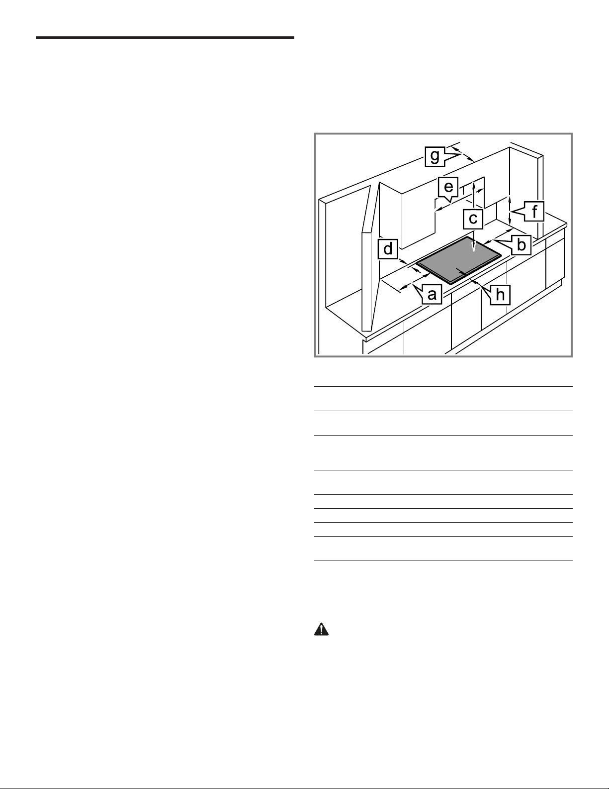
The minimum spaces that must be maintained when installing the gas cooktop shall be the following:
a min. 13" (330mm)
for installation next to oven min. 13" (330mm)
b min. 13" (330mm)
for installation next to oven min. 13" (330mm)
c min. 30" (762mm) clearance between the top of
the cooking surface and the bottom of combustible
constructions
d min 3" (76mm);
for installation in kitchen islands, min. 4" (100mm)
e min. 30" (760mm) centered over cooktop
f min. 18" (458mm)
g max. 13" (330mm)
h min. 1¾" (48mm);
for installation in kitchen islands, min. 4" (100mm)
Ensure that the following requirements are met when planning the installation of your appliance.
¡ Plan the installation of the unit so that the power cord,
gas shut-off valve and gas pressure regulator are accessible from the front of the cabinet.
¡ Make sure the gas supply line does not interfere with
the back of the appliance.
¡ The cabinet in which the cooktop is installed must be
properly secured, level and stable.
¡ Any laminated coverings and glue on cabinets next to
the cooktop must be made of non-flammable and heat
resistant materials. Refer to local building codes for acceptable materials.
¡ This appliance cannot be installed above refrigerators,
washing machines, dishwashers or similar.
2.5 Countertop requirements
Ensure that the countertop into which the cooktop is to be
installed meets these requirements for a safe installation.
WARNING
To reduce the risk of ignition of surrounding combustible
materials, install at least 13" (330mm) from both sidewalls
and at least 3" (76mm) from the rear wall.
¡ The countertop must be level.
¡ The stability of the countertop must be maintained after
the cut-out has been made.
7
Page 8
en-us Prepare installation space
¡ Solid surface or laminate countertops often require spe-
cial installations. For example, heat-reflective tape and
rounded corners may be necessary. Contact the countertop manufacturer for instructions specific to your
countertop.
2.6 Gas requirements
Ensure that the requirements for the gas supply are met.
The cooktop is shipped from the factory for use with natural gas. For use with LP conversion, a certified technician
or installer must do the conversion.
Supply pressure:
¡ Natural Gas: 7 inches water column (17.4 Millibars)
¡ Propane Gas: 11 inches water column (27.4 Millibars)
¡ The propane gas tank must be equipped with its own
high pressure regulator in addition to the pressure regulator supplied with this unit.
2.7 Electrical requirements
Ensure that the following electrical requirements are met.
CAUTION
Do not use an extension cord with this appliance.
¡ This appliance requires a 60Hz, 15Amp, 120V/AC
connection.
¡ The appliance is equipped with a 40" (1000mm) power
cord.
¡ The power connection must remain accessible from the
front of the cabinet after the installation is complete.
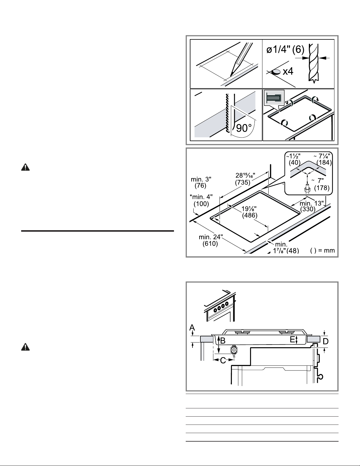
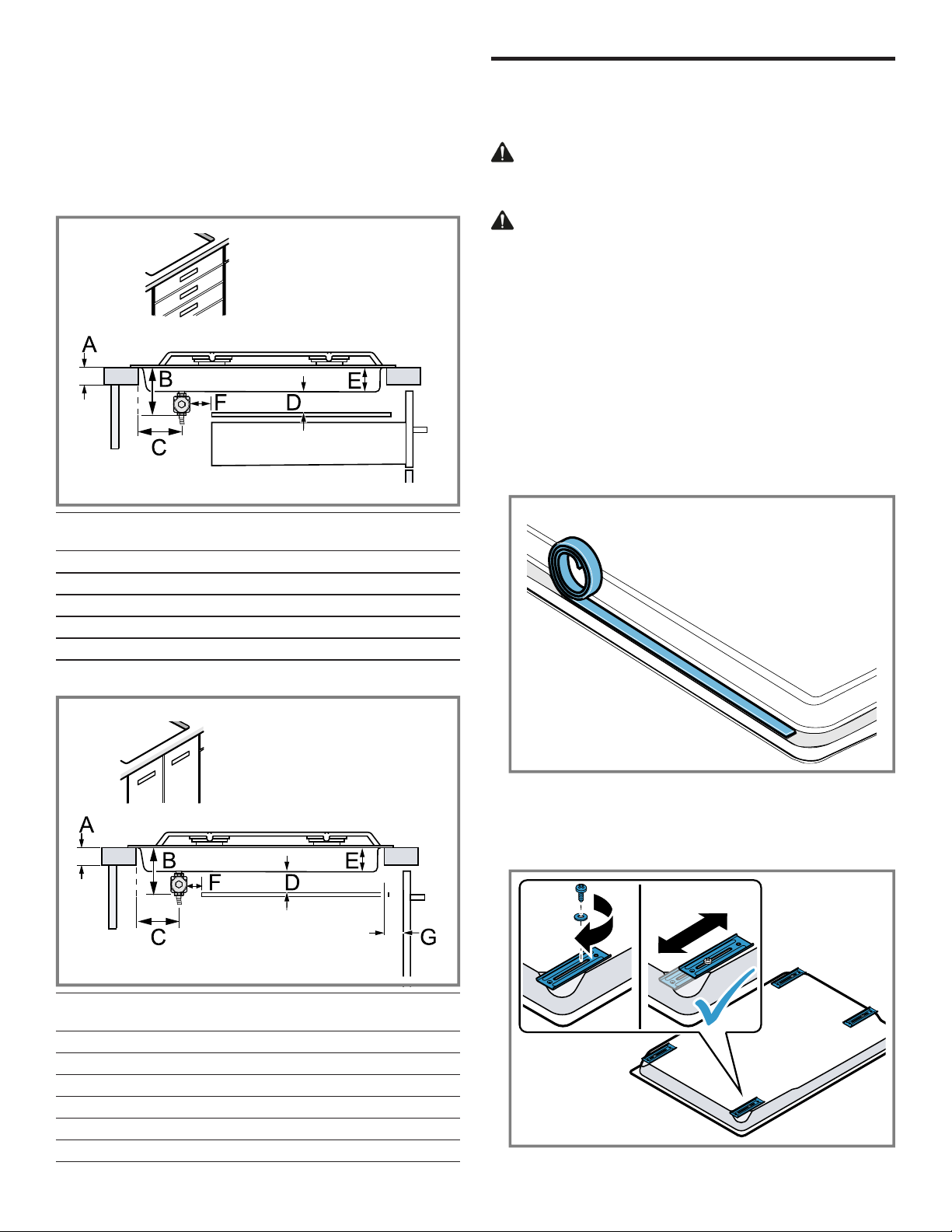
3.1 Installation dimensions
Prepare installation space
3 Prepare installation space
Prepare installation space
Create the cutout in the countertop according to the instructions.
General countertop requirements:
¡ The angle of the cut surface to the countertop surface
must be 90°.
¡ With multi-layered countertops, secure strips laterally in
the cutout if necessary.
¡ After creating the cutout, remove all debris.
¡ Follow the countertop manufacturer's recommendations
for protecting the cut edges, e.g. apply heat resistant foil
tape.
¡ If the cooktop will be installed in combination with an
oven, refer to the Approved Combination Matrix included with the product for cutout and clearance dimensions.
WARNING
The bottom of the cooktop can become hot.
▶ If the cooktop is not installed in combination with an
oven, install a horizontal panel below the cooktop to
prevent accidental contact. Refer to the section on installing a horizontal panel. →
Page9
*For installation in a kitchen island.
Installation over oven
A min. ¾" (19 mm)
max. 2" (50 mm)
B 5⅞" (150 mm)
C 2¾" (70 mm)
D Refer to Approved Combination Matrix
E 2⅜" (60)
8
Page 9
Installation procedure en-us
Installation with horizontal panel
If there is no oven beneath the cooktop, install a horizontal
panel. To allow access to the power supply connection
and regulator maintain a minimum clearance of
⅜" (10mm) from the edges of the panel(F).
IMPORTANT: Complete the installation of the cooktop before installing the horizontal panel.
Installation above a drawer
Installation procedure
4 Installation procedure
Installation procedure
Follow these instructions to install the cooktop into the
countertop.
CAUTION
Sharp edges.
▶ Use protective gloves when installing the appliance.
CAUTION
The appliance is heavy.
▶ It is recommended that two people install this appliance.
4.1 Preparing the cooktop
Note:ONLY FOR MODEL NGM8648UC: If the appliance
is to be used with LP gas, carry out the LP gas conversion
BEFORE installing the appliance in the countertop.
→
"Conversion to LP gas", Page13
1. Place the cooktop face down on a soft and stable sur-
face. Use the foam sheet from the packaging to protect
surfaces from scratching.
2. Apply the included foam sealing tape around the edges
of the underside of the appliance along the rough-in box
flange.
A min. ¾" (19 mm)
max. 2" (50 mm)
B 5⅞" (150 mm)
C 2¾" (70 mm)
D min. 0" (0 mm)
E 2⅜" (60)
F min. ⅜" (10 mm)
Installation above a cabinet door
3. Attach the hold-down brackets to the underside of the
cooktop with the provided short screws and washers.
Loosely tighten the screws so the clamps do not move
freely. Rotate the hold-down brackets so that the appliance can be placed in the cutout.
A min. ¾" (19 mm)
max. 2" (50 mm)
B 5⅞" (150 mm)
C 2¾" (70 mm)
D min. 0" (0 mm)
E 2⅜" (60)
F min. ⅜" (10 mm)
G min. 1" (25)
9
Page 10
en-us Installation procedure
Note:The rating plate will not be accessible after installation. Make a note of your appliance's details or refer to the
enclosed appliance certificate.
→
"Rating plate location", Page17
4.2 Installing the pressure regulator
WARNING
Do not attempt any adjustment of the pressure regulator,
except when converting to propane. Adjustments could
lead to leaks or cause incorrect gas pressure to the appliance.
Make sure the used gas connection line is not connected
to the gas supply, before carrying out the following steps.
Note:All pipe connections must be sealed in accordance
with local codes.
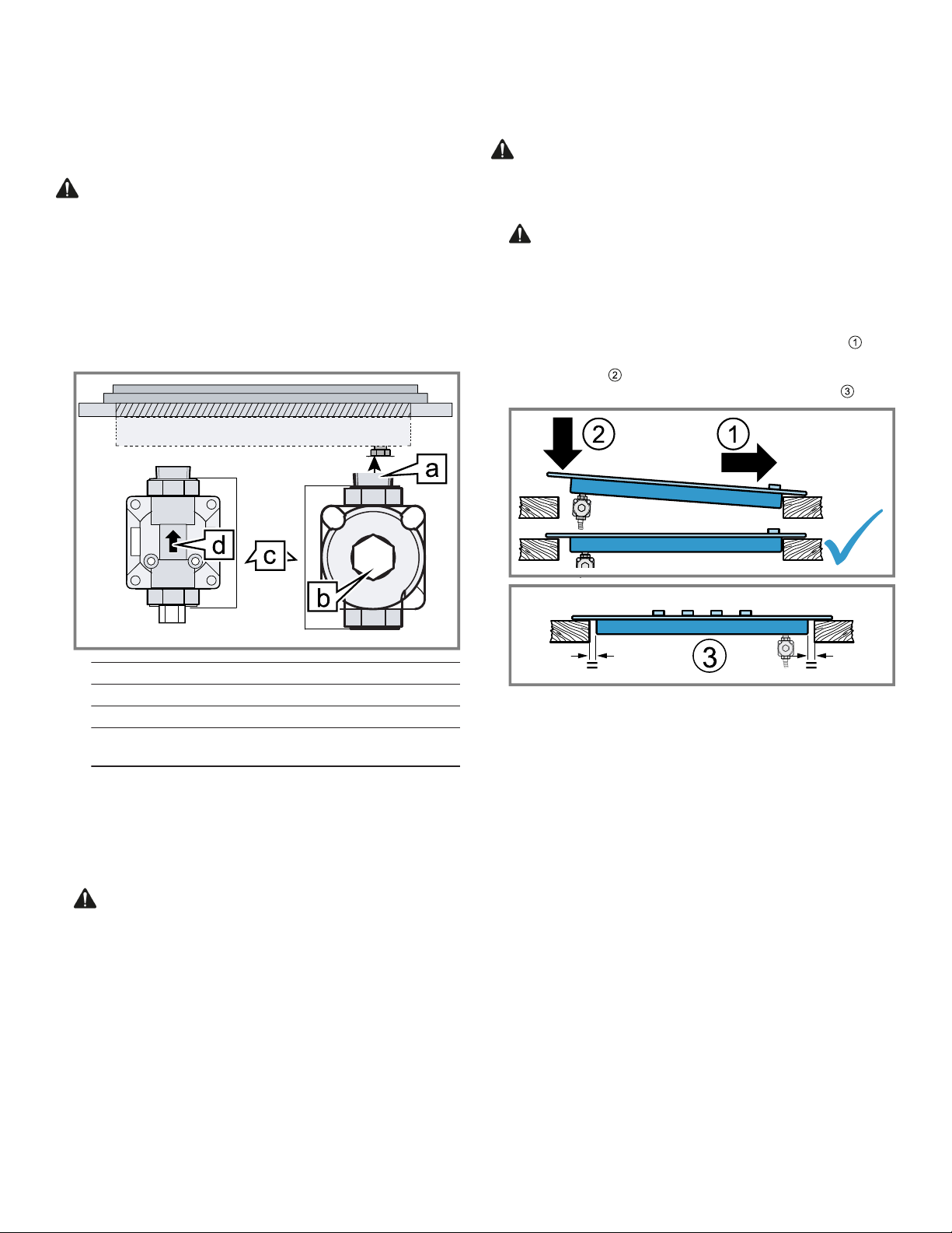
1. Identify the parts of the pressure regulator.
4.3 Securing the cooktop to the countertop
The cooktop must be secured from below using the holddown brackets provided.
WARNING
Before installing, turn power OFF at the service panel.
▶ Lock service panel to prevent power from being turned
ON accidentally.
1.
CAUTION Do not let the cooktop drop into place.
▶ Make sure that the cooktop is supported along the
edges when carefully placing it into the cutout.
Turn the cooktop over carefully making sure not to damage the pressure regulator and gas line.
‒ Place the cooktop carefully into the countertop
cutout, pulling it towards the front of the cutout .
‒ Lower the rear of the cooktop so that is rests flat on
the counter .
‒ Center the cooktop left and right in the cutout .
a Appliance manifold connection
b Conversion cap
c Pressure regulator
d Arrow on pressure regulator, shows the direc-
tion of gas flow
2. Apply Teflon® tape on the threads of the manifold pipe.
Install the pressure regulator (supplied with cooktop) to
the gas inlet with the gas flow arrow facing the manifold
inlet.
3. Firmly hand tighten the regulator, then further tighten ¼
turn to a maximum of one complete turn. Align the regulator so that the conversion cap is easily accessible.
4.
WARNING Never reuse a gas connector. Repeated bending, flexing, or extreme vibration will cause
metal fatigue and must be avoided.
Apply Teflon® tape to the male threads, then connect a
new ½" metal flex line or fixed metal pipe connection to
the pressure regulator.
Note:For installations with little space, use a 90° street
elbow (not supplied) to orient the regulator horizontally.
10
Page 11

Installation procedure en-us
2. Insert the 2½" clamping screws into the threaded holes
of the hold-down brackets, slide or rotate the brackets
so that the clamping screws will contact the underside
of the countertop.
‒ Protect delicate countertops by placing a wooden
disk underneath.
‒ Hand-tighten the first screw and check the cooktop
position, then secure the cooktop by tightening all
clamping screws .
‒ Tighten the screws to the cooktop .
Note:Do not use silicone to glue the cooktop to the
countertop surface.
4.4 Connection overview
Refer to this illustration for the location of the gas and
electric connection of the appliance.
Note:Your appliance is equipped for use with natural gas
on delivery. If you want to use your appliance with LP gas
refer to the section on LP gas conversion before continuing with the installation. →
Page13
g 120V receptacle
h Gas cut-off valve
i Gas supply line connection fitting
j Floor
4.5 Connecting the gas supply line
The appliance is shipped from the factory for use with natural gas. If you want to use propane gas it must be converted. A qualified technician or installer must do the conversion.
Note
Ensure the following requirements are met before you try
to connect the appliance to the gas supply:
¡ Before connecting the appliance, check whether the lo-
cal connection conditions such as gas type and gas
pressure match the appliance settings.
¡ Make sure the gas supply is turned off at the manual
shutoff valve before connecting the appliance.
¡ The gas connection must be in a location that permits
access to the manual shut-off valve and which, if applicable, is visible after opening the door or drawers of the
cabinet.
¡ The metal flex gas line must not come into contact with
moving parts of the fitted unit (e.g. drawers) or be laid in
areas where it could become trapped or damaged.
¡ The metal flex gas line must not come into contact with
a cooktop, oven, dishwasher, refrigerator, washing machine, hot water pipe, radiator or any other appliance installed in the vicinity of the gas cooktop.
¡ The metal flex gas line must not be subject to rubbing,
vibrations, kinking or any other kind of deformation. It
should be checked along its entire length with the cooktop in the installation position.
¡ All pipe connections must be sealed in accordance with
local codes.
▶ Connect the metal flex gas line or fixed metal pipe con-
nection from the cooktop pressure regulator to the manual shut-off valve.
a Cooktop rough-in box
b Arrow on pressure regulator, shows the direction of
gas flow
c Pressure regulator
d ½" female pipe threads
e Metal flex gas line
f Power cord (40"/1m)
Checking the gas line for leaks
Check the gas supply line connections for leaks using a
soap solution or non-corrosive leak detection fluid. Do not
use a flame of any sort.
Note
Important notes for gas connection:
¡ The appliance and its individual shutoff valve must be
disconnected from the gas supply piping system during
any pressure testing at pressures in excess of ½psi
(3.5kPa).
¡ The appliance must be isolated from the gas supply pip-
ing system by closing its individual manual shutoff valve
during any pressure testing of the gas supply piping
system at test pressures equal to or less than ½psi
(3.5kPa).
1. Turn on gas.
2. Apply a soap solution or non-corrosive leak detection
fluid to all joints and fittings in the gas connection between the shut-off valve and the cooktop. Also check
gas fittings and joints in the cooktop if the connections
may have been disturbed during installation.
a Bubbles appearing around fittings and connections indi-
cate a leak.
11
Page 12
en-us Installation procedure
1
2
3
4
4
3
2
1
1
2
3
4
3. If a leak appears, turn off the supply line gas shut-off
valve and tighten the connections.
4. Retest for leaks by turning on the supply line gas shutoff
valve.
a When the leak check is complete and no bubbles ap-
pear, the test is complete.
5. Wipe off all soap solution or detection fluid residue.
4.6 Connecting the electrical supply
CAUTION
Before you plug in the electrical cord, make sure that the
gas shut-off valve and all burner controls are in the OFF
position.
▶ Connect the plug of the electrical cord to a grounded
power outlet. The outlet must be accessible after the installation of the appliance is complete.
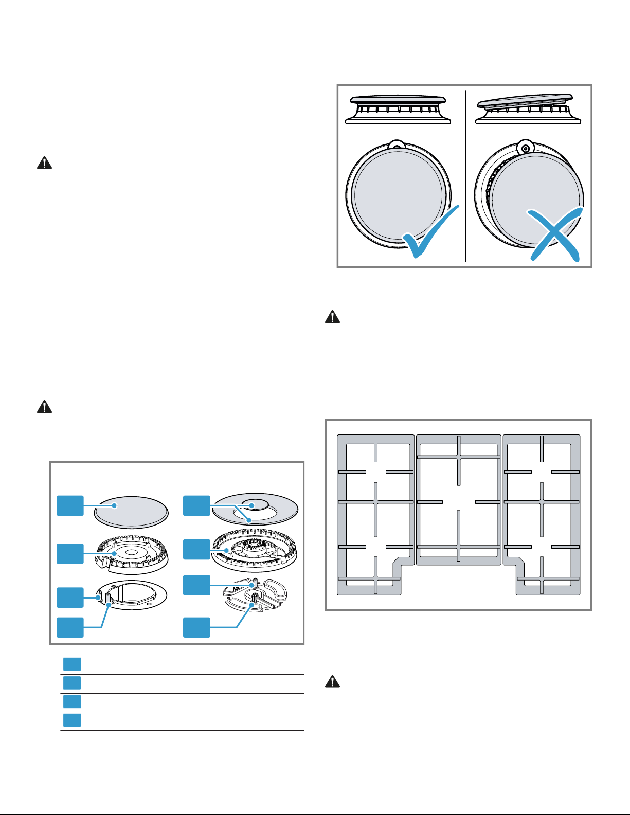
4.7 Assembling the burner parts
The burner parts must be properly placed for the cooktop
to function properly.
Note
If the burner parts are not properly placed, one or more of
the following problems may occur:
¡ The burner flames are too high.
¡ Flames shoot out of the burners.
¡ The burners do not ignite.
¡ The burner flames light unevenly.
¡ The burners emit gas odor.
WARNING
Remove all tape from the burner parts and the cooktop
surface before using the appliance.
2. Check to make sure that there is no gap between the
burner parts. You may gently try to move the burner
parts from side to side to check if they are properly
seated.
4.8 Installing the burner grates
WARNING
Improperly positioned grates can cause flare-ups.
▶ Position all grates properly on the cooktop whenever
the cooktop is in use to properly support pots and avoid
spills.
▶ Make sure each of the four feet of the grates is placed
into the corresponding dimples on the cooktop surface.
▶ Do not use a grate if the rubber feet are missing or
damaged.
1. Assemble the burner parts according to the illustration.
Burner cap
Burner base
Thermocouple
Igniter
Make sure that the prongs of the burner cap fit snugly
into the groove of the burner base.
4.9 Checking the installation
Check if your unit is working properly after you have completed the installation steps.
WARNING
Before you turn on power supply, make sure all controls
are in the OFF position.
1. Ensure that the burner caps are properly positioned.
2. Turn each burner on in turn and verify that the electric
igniters are working.
12
Page 13
Conversion to LP gas en-us
3. Turn the control knob between the highest and lowest
setting. Make sure the flame does not go out and there
are no flashbacks.
4. If you have carried out an LP gas conversion, check the
lowest setting to confirm the flames are stable on the
ports and the set screws do not need to be readjusted.
5. Check the flame characteristics.
6. After completing all checks, complete the installation of
the horizontal panel or oven. →
Page9
Note:The appliance is shipped from the factory for use
with natural gas. If you want to use propane gas, it must
be converted. A qualified technician or installer must do
the conversion. Refer to Conversion to LP gas.
→
Page13
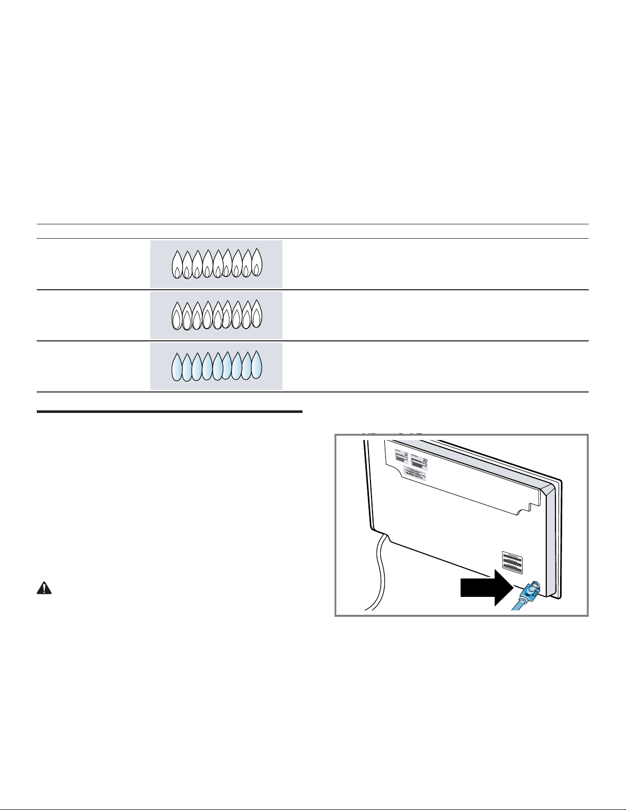
The flame should be blue with a minimal yellow tip on
the outer cone.
Flame characteristics
The color of the flame tells you if the gas supply is properly adjusted.
Note:Allow the appliance to operate for 4 to 5minutes before evaluating the flame. Some yellow streaking is normal dur-
ing the initial startup.
Flame Image Measure
Completely or mostly
yellow
Yellow tips on outer
Verify that the regulator is set for the correct fuel. Retest after adjustment.
Normal for LP gas
cone
Soft blue Normal for natural gas
Conversion to LP gas
5 Conversion to LP gas
Conversion to LP gas
Your appliance is equipped for use with natural gas on de-
1. Locate the pressure regulator on the bottom right end of
the appliance.
livery. It can be converted to LP gas supply.
The components required for conversion to LP gas are
contained in the LP conversion kit included with this appliance, or are available from Customer Service.
→
"Customer Service", Page17
Only a qualified technician or installer is authorized to convert the appliance to another gas type.
Before carrying out the conversion, turn off the electricity
and gas supply.
5.1 Converting the pressure regulator
WARNING
Turn off the electricity and gas supply before carrying out
the conversion.
Requirement:Complete the installation instructions in this
manual up to and including section
→
"Securing the cooktop to the countertop", Page10
fore starting the LP conversion.
be-
13
Page 14

en-us Conversion to LP gas
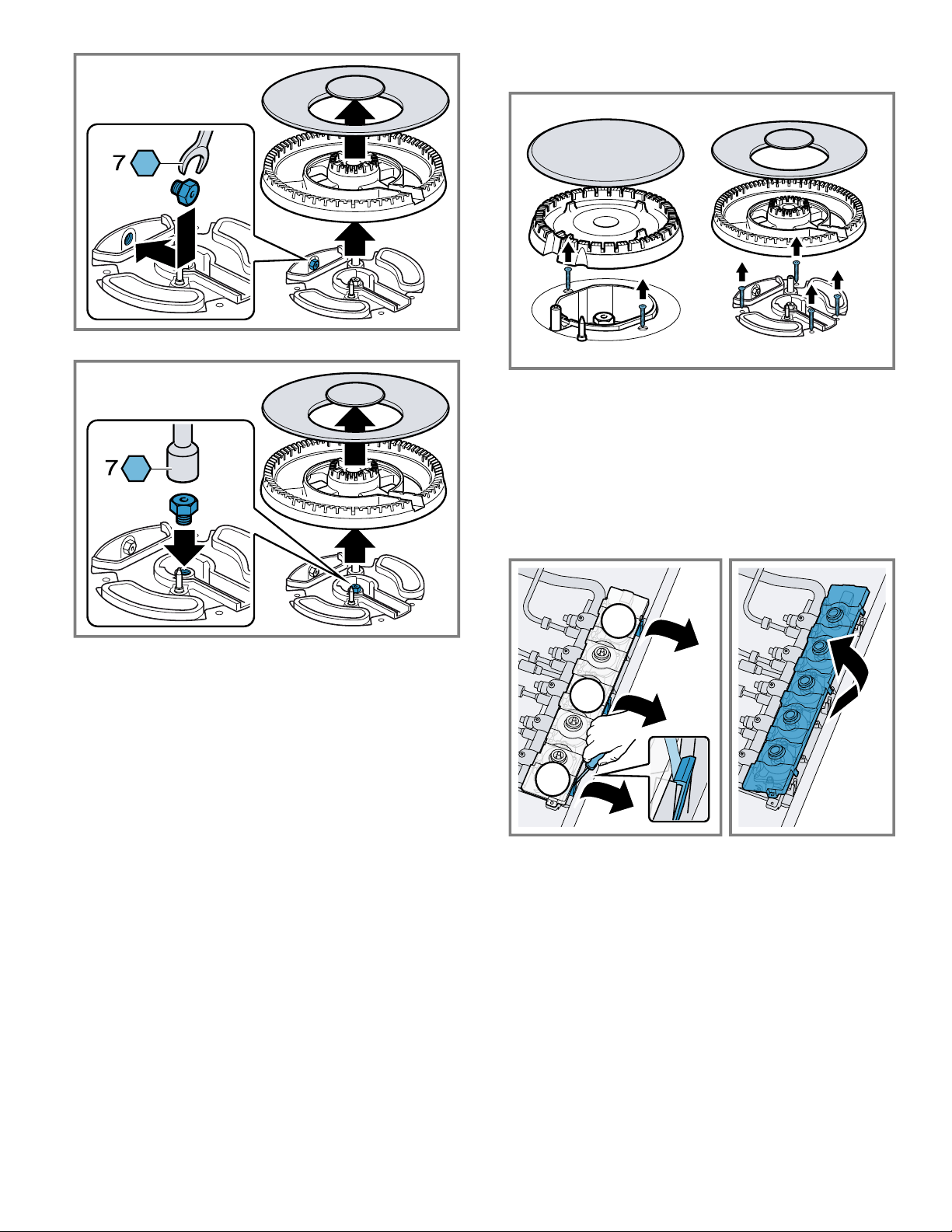
2. Remove the hexagon shaped conversion cap from the
regulator. Make sure not to dislodge the gasket on
the cap or the spring inside the regulator.
3. Grasp the plastic orifice stem firmly and pull it force-
fully from the conversion cap . The stem snaps snugly
into an indent in the cap and may require a strong pull
to remove. It may be helpful to gently “rock” the plastic
stem while pulling it from the metal cap.
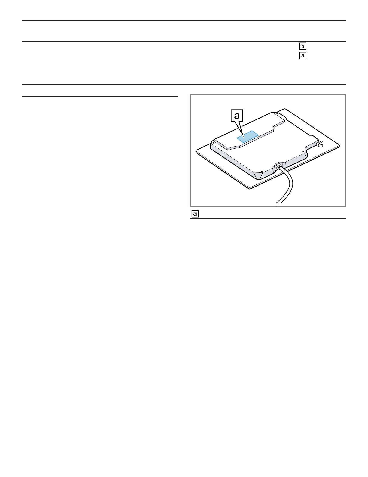
7. IMPORTANT: Attach the metallic sticker included with
the LP conversion kit to the bottom of the appliance as
shown. This sticker provides notice that the appliance
has been converted for use with LP gas. It should be located near the appliance rating plate.
→
"Rating plate location", Page17
Note:If you change the type of gas back to natural gas
at a later point, remove the sticker.
4. Rotate the stem 180° .
a Confirm that the button end of the orifice stem is away
from the conversion cap.
a Confirm that the letters “LP” on the orifice stem are up-
side down when the conversion cap is set flat on its
head.
5. Snap the orifice stem back in place in this position in-
serting it into the indent in the conversion cap .
6. Insert the hexagon cap back into the regulator and
tighten, do not over-tighten.
5.2 Replacing the orifices
1. Remove all burner grates, burner caps and burner
bases.
2. Remove the natural gas orifices and replace them with
LP orifices using a 7mm socket wrench. See burner
chart →
‒ For ease of installation use a small piece of tape and
‒ It is important to make sure that the orifices do not
Page16
.
insert it in the socket wrench to prevent the orifice
from falling out.
become detached during removal or fastening. They
must be properly tightened to ensure that there are
no leaks.
14
Normal burner with one orifice
Page 15
Double burner, first orifice
1
2
3
Conversion to LP gas en-us
3. Remove the screws at each burner and lift off the main
top from the cooktop.
Note:Do not remove the illuminated rings under any
circumstances. You will require Customer Service to refit them.
4. Remove the electronics pack from the control panel:
‒ With a flat head screwdriver carefully pry the black
tabs at the front away from the panel one by one,
while lifting up the transparent cover of the electronics pack to disengage the tabs.
‒ When all tabs are unlocked you can lift off the elec-
tronics pack.
Double burner, second orifice
3. Fasten the orifices.
4. Save the orifices removed from the appliance for future
use.
5.3 Adjusting the gas valves
1. Turn the control knobs to position 0.
2. Pull off the control knobs.
5. Remove the black disks from the valve stems. Make
sure the springs underneath the black disks do not
come off.
15
Page 16

en-us Conversion to LP gas
6. Adjust the black T10 star head setting screw with a T10
star head screwdriver. Refer to the burner chart for the
correct setting of the setting screws(M).
→
"Burner chart", Page16
‒ Use setting for LP Gas. The setting screws must
be tightened properly.
‒ Use setting for natural gas. The setting screws
must finish flush with the fitting.
The dual-flame burner has 2setting screws.
7. Replace the black disks.
8. Replace the electronics pack applying light pressure so
the tabs engage. Make sure not pinch any connecting
cables.
9. Ensure that the gaskets around the burner bases are in
place.
5.4 Burner chart
Refer to this overview for specifications of the individual burners.
Burner
cap
Small
burner
Gas type Pressure
in inch
wc
Natural gas
Propane gas
6
10
Orifice BTU/h kW M (valve ad-
77
54
10.Reinstall the main top and the control knobs.
11.Replace all burner bases, burner caps and burner
grates.
12.Continue the installation procedure from
→
"Connection overview", Page11
13.When the installation is complete, verify that the appli-
ance works properly.
→
"Checking the installation", Page12
.
Note:In the event of damage, the valve must be completely replaced.
justment screw
setting)
3,400
3,400
1.00
1.00
Large
burner
Medium
burner
16
Natural gas
Propane gas
Natural gas
Propane gas
6
10
6
10
133
93
102
71
10,300
10,300
6,000
6,000
3.00
3.00
1.75
1.75
Page 17
Customer Service en-us
Burner
cap
Gas type Pressure
in inch
Orifice BTU/h kW M (valve ad-
wc
Dual
burner
Natural gas
Propane gas
6
10
NG:
¡ outer: 161
¡ inner: 74
PG:
¡ outer: 105
¡ inner: 39
Customer Service
6 Customer Service
Customer Service
If you have any questions on use, are unable to eliminate
an issue in the appliance yourself, or the appliance needs
to be repaired, please contact our Customer Service.
With any warranty repair, we will make sure your appliance is repaired by an authorized service provider using
genuine replacement parts. We use only genuine replacement parts for all repairs.
Detailed information on the warranty period and terms of
warranty can be found in the Statement of Limited Product
Warranty, from your retailer, or on our website.
If you contact the Customer Service, you will need the
model number (E-Nr.) and the production number (FD) of
your appliance.
USA:
1-877-442-4436
www.gaggenau.com
www.gaggenau.com/us/appliances/eshop
CA:
1-877-442-4436
www.gaggenau.com
www.gaggenau.ca
17,000
14,500
Rating plate
justment screw
setting)
5.00
4.30
6.1 Model number (E-Nr.) and production number (FD)
You can find the model number (E-Nr.) and the production
number (FD) on the appliance's rating plate.
Making a note of your appliance's details and the Customer Service telephone number will enable you to find
them again quickly.
6.2 Rating plate location
You can find the rating plate of your appliance:
¡ On the appliance certificate.
¡ On the underside of the appliance.
17
Page 18

fr-ca
Table des matières
1 IMPORTANTES CONSIGNES DE SÉCURITÉ .........19
1.1 Définitions des termes de sécurité ...........................20
1.2 Indications générales ...............................................20
1.3 Consignes générales de sécurité .............................20
1.4 Manipulation sécuritaire des appareils .....................21
1.5 Codes et normes de sécurité ...................................21
1.6 Sécurité électrique ...................................................21
1.7 Sécurité des gaz ......................................................22
1.8 Installation au gaz propane ......................................22
1.9 Recommandations de ventilation .............................22
1.10 Installation à haute altitude.....................................22
1.11 Mises en garde conformément à la proposition
65 de l'État de Californie ........................................23
2 Avant de commencer...............................................24
2.1 Pièces incluses ........................................................24
2.2 Outils et pièces nécessaires.....................................24
2.3 Conditions générales ...............................................24
2.4 Exigences concernant les armoires..........................24
2.5 Exigences du comptoir.............................................25
2.6 Exigences en matière de gaz ...................................25
2.7 Exigences électriques ..............................................25
3 Préparation préalable au montage .........................25
3.1 Dimensions de l’installation......................................25
4 Procédure d’installation ..........................................26
4.1 Préparation de la table de cuisson ...........................26
4.2 Installation du régulateur de pression.......................27
4.3 Fixation de la table de cuisson au comptoir..............27
4.4 Aperçu de la connexion............................................28
4.5 Raccordement de la conduite d’alimentation en
gaz...........................................................................28
4.6 Connexion de l'alimentation électrique .....................29
4.7 Assemblage des pièces du brûleur ..........................29
4.8 Installation des grilles de brûleur..............................30
4.9 Inspecter l’installation...............................................30
5 Conversion au gaz LP..............................................31
5.1 Conversion du régulateur de pression......................31
5.2 Remplacement des orifices......................................32
5.3 Ajustement des soupapes de gaz ............................32
5.4 Tableau des brûleurs ...............................................34
6 Service à la clientèle................................................34
6.1 Numéro de modèle (E-Nr.) et numéro de
fabrication (FD) ........................................................34
6.2 Emplacement de la plaque signalétique...................34
18
Page 19

fr-ca
IMPORTANTES CONSIGNES DE SÉCURITÉ
LIRE ET CONSERVER CES INSTRUCTIONS
Lisez toutes les instructions attentivement avant l’utilisation. Ces précautions réduiront le risque d’électrocution,
d’incendie et de blessure pour les personnes utilisant l’appareil. Lorsque vous utilisez des appareils électroménagers,
il importe de suivre les précautions de sécurité de base, y compris celles indiquées dans les pages suivantes.
19
Page 20

fr-ca
IMPORTANTES CONSIGNES DE SÉCURITÉ
LIRE ET CONSERVER CES INSTRUCTIONS
1.1 Définitions des termes de sécurité
Vous trouverez ici des explications sur les mots de
signalisation de sécurité utilisés dans ce manuel.
AVERTISSEMENT
Signale un risque de mort ou de blessure grave si
l’avertissement n’est pas respecté.
MISE EN GARDE
Signale un risque de blessures mineures ou modérées si
l’avertissement n’est pas respecté.
AVIS :
Ceci indique que la non-conformité à cet avis de sécurité
peut entraîner des dégâts matériels ou endommager
l'appareil.
Remarque:Ceci vous signale des informations et/ou
indications importantes.
1.2 Indications générales
¡ Lisez attentivement cette notice.
¡ Veuillez conserver la notice et les renseignements sur
le produit en vue d’une réutilisation ultérieure ou pour
un futur nouveau propriétaire.
¡ Ne branchez pas l’appareil si ce dernier a été
endommagé durant le transport.
1.3 Consignes générales de sécurité
IMPORTANT: L'APPAREIL DOIT ÊTRE INSTALLÉ PAR
UN INSTALLATEUR QUALIFIÉ.
IMPORTANT: CONSERVEZ CES INSTRUCTIONS
POUR L’UTILISATION DE L’INSPECTEUR
ÉLECTRIQUE LOCAL.
PROPRIÉTAIRE: VEUILLEZ CONSERVER CES
INSTRUCTIONS POUR RÉFÉRENCE FUTURE.
INSTALLATEUR: LAISSEZ CES INSTRUCTIONS AVEC
L'APPAREIL UNE FOIS L'INSTALLATION COMPLÈTE.
Examinez l'appareil après l'avoir déballé. En cas de
dommage en cours de transport, ne branchez pas
l'appareil.
AVERTISSEMENT
Si les consignes du présent manuel ne sont pas suivies à
la lettre, il y a un risque d’incendie ou d’électrocution
pouvant entraîner des dommages matériels ou des
blessures.
Ne pas réparer, remplacer ni retirer toute pièce de
l’électroménager à moins que cela ne soit spécifiquement
recommandé par les manuels. L’installation, les
réparations ou l’entretien inadéquats pourraient causer
des blessures ou des dégâts matériels.
▶ Consulter ce manuel pour les directives d’utilisation.
▶ Toutes les autres réparations doivent être effectuées
par un prestataire de services agréé.
Couper l’alimentation électrique et de gaz avant toute
réparation.
Lorsque vous installez une table de cuisson sur un seul
four, veillez à suivre les instructions des manuels
d'installation du four et de la table de cuisson.
Ne jamais modifier ni altérer la structure de l’appareil
électroménager.
Utilisez uniquement l’appareil électroménager s’il a été
installé par un technicien qualifié conformément aux
présentes instructions d’installation. Le fabricant ne peut
pas être tenu responsable de tous dommages causés par
une installation inadéquate.
Pour éliminer le risque de brûlure ou d'incendie lorsque
vous vous étirez au-dessus des surfaces chauffantes de
l'électroménager, il faut éviter d'installer des armoires de
rangement au-dessus de la surface de l'électroménager.
▶ Si une armoire de rangement est installé, il est possible
de réduire le risque en installant une hotte qui dépasse
(horizontalement) d'au moins 5po (127mm) le bord du
fond de l'armoire.
▶ Vérifier que la profondeur des armoires au-dessus de la
table de cuisson est au maximum de 13po (330mm).
AVERTISSEMENT
Le dessous de la table de cuisson peut devenir chaud.
▶ Si la table de cuisson n'est pas installée en
combinaison avec un four, installez un panneau
horizontal sous la table de cuisson pour éviter tout
contact accidentel. Reportez-vous à la section sur
l'installation d'un panneau horizontal. →
AVERTISSEMENT
Retirer tout le ruban adhésif et l'emballage avant d'utiliser
l'électroménager.
Page26
▶ Jetez l'emballage après avoir déballé l'électroménager.
▶ Éliminez l'emballage d'une manière respectueuse de
l'environnement.
▶ Ne laissez jamais les enfants jouer avec le matériel
d’emballage.
20
Page 21

IMPORTANTES CONSIGNES DE SÉCURITÉ
LIRE ET CONSERVER CES INSTRUCTIONS
fr-ca
▶ Conservez les pièces de petite taille dans un endroit
sûr, car elles peuvent être avalées facilement.
1.4 Manipulation sécuritaire des appareils
AVERTISSEMENT
Certaines surfaces cachées peuvent avoir des
rebords tranchants.
▶ Redoubler de vigilance quand vous passez la main
derrière ou sous l'appareil électroménager.
1.5 Codes et normes de sécurité
Cet appareil est conforme aux plus récentes versions de
l'une ou plus des normes suivantes:
¡ ANSIZ21.1/CSA1.1, Appareils électroménagers pour
la cuisson à gaz
¡ L’installation doit être conforme aux codes locaux ou,
en l’absence de tels codes, au National Fuel Gas Code
ANSIZ223.1/NFPA54 ou, au Canada, au code
national CSAB149.1 d’installation du gaz naturel et du
propane.
Il est de la responsabilité du propriétaire et de l'installateur
de déterminer si des exigences et/ou des normes
supplémentaires s'appliquent à des installations
spécifiques.
1.6 Sécurité électrique
¡ Installateur - indiquez au propriétaire l’emplacement
du disjoncteur ou du fusible. Identifiez sa position pour
pouvoir le retrouver facilement.
¡ S’il y a lieu, conformément au Code national de
l’électricit (ou au Code canadien de l’électricité), cet
appareil doit être installé sur un circuit de dérivation
séparé.
¡ Les codes locaux peuvent varier. L'installateur est
responsable de s'assurer que l'installation, les
connexions et la mise à la terre sont conformes à tous
les codes applicables. Le fabricant n'est pas
responsable des problèmes associés à une mauvaise
installation de ce produit.
¡ L’appareil doit être mise à la terre en conformité aux
codes locaux, ou en l’absence de tels codes, à la
dernière version du National Electric CodeNFPA70
ou, au Canada, au code canadien de
l’électricitéCSAC22.1-02.
¡ Assurez-vous que l’appareil est correctement installé et
mis à la terre par un technicien qualifié. L’installation,
les raccordements électriques et la mise à la terre
doivent être conformes avec tous les codes en vigueur.
¡ N'utilisez pas de rallonge.
¡ N'utilise pas un adaptateur.
¡ Voir la fiche signalétique pour plus d'information.
→
"Emplacement de la plaque signalétique", Page34
AVERTISSEMENT
Avant l'installation, couper l'alimentation au panneau de
service.
▶ Verrouiller le panneau de service pour empêcher que
l'alimentation ne soit rétablie par accident.
Pour les électroménagers dotés d'un cordon
d'alimentation avec fiche, ne pas couper ni enlever la
broche de mise à la terre.
▶ Pour éviter toute électrocution, brancher le cordon dans
une prise de courant correspondante avec mise à la
terre.
▶ En cas de doute concernant la mise à la terre
appropriée de la prise murale, le client doit faire vérifier
celle-ci par un électricien qualifié.
INSTRUCTIONS DE MISE À LA TERRE
▶ Cet appareil doit être mis à la terre.
▶ La mise à la terre réduit le risque de choc électrique en
fournissant une voie sûre pour le courant électrique en
cas de court-circuit.
▶ Assurez-vous que l’appareil est correctement installé et
mis à la terre par un technicien qualifié.
▶ L’installation, les raccordements électriques et la mise
à la terre doivent être conformes avec tous les codes
en vigueur.
N'utilisez pas de rallonge. Si lecordon d'alimentation est
trop court, demandez à unélectricienouun technicien
qualifié d'installerune prise à proximité de l'appareil.
Avant de brancher le cordon électrique, vérifie que toutes
les commandes sont à la position OFF (Arrêt).
Avant de mettre sous tension la source d'alimentation,
vérifiez que toutes les commandes sont à la position OFF
(Arrêt).
21
Page 22

fr-ca
IMPORTANTES CONSIGNES DE SÉCURITÉ
LIRE ET CONSERVER CES INSTRUCTIONS
1.7 Sécurité des gaz
Exigences pour l'alimentation en gaz:
¡ Installer un robinet d'arrêt près de l'électroménager. Il
doit être facilement accessible en cas d'urgence.
¡ L'installateur doit procéder au test de fuites selon les
consignes fournies dans le présent manuel.
¡ L'appareil et son propre robinet d'arrêt doivent être
déconnectés de la canalisation du système
d'alimentation en gaz au cours de test aux pressions
qui dépassent ½PSI (3,5kPa).
¡ L’électroménager doit être isolé de la canalisation du
système d'alimentation en gaz en fermant son propre
robinet d'arrêt manuel pour tout test de pression à des
pressions égales ou inférieures à ½PSI (3,5kPa).
¡ La pression d'alimentation minimale doit être de 1po
de colonne d'eau au-dessus de la pression d'admission
imprimée sur l'étiquette signalétique. La pression
d'admission maximum ne doit pas excéder 14po de
colonne d'eau (34,5millibars).
¡ Une ligne de production métallique souple ou un tuyau
métallique fixe doit être utilisé pour raccorder le gaz à
l'appareil. Si une conduite de gaz en métal ne peut pas
être utilisée, veuillez vous adresser à un électricien
agréé local ou aux codes électriques locaux pour
obtenir une mise à la terre appropriée.
AVIS DE SÉCURITÉ IMPORTANT: La combustion du
combustible de cuisson au gaz génère certains sousproduits qui figurent sur la liste des substances reconnues
par l'État de Californie comme cancérigènes ou pour la
reproduction. Pour minimiser l'exposition à ces
substances, faites toujours fonctionner cet appareil
conformément aux instructions contenues dans ce livret et
assurez une bonne ventilation.
1.8 Installation au gaz propane
¡ Le réservoir de gaz propane doit être doté de son
propre régulateur de pression élevée. De plus, le
régulateur de pression livré avec cet appareil doit aussi
être utilisé.
¡ L'électroménager est livré de l'usine prêt à utiliser avec
du gaz naturel. Il doit être converti pour usage avec gaz
propane. Un technicien qualifié ou un installateur
certifié doit procéder à la conversion.
¡ Pour une utilisation avec du propane, l'appareil doit être
converti selon les instructions de conversion LP.
→
"Conversion au gaz LP", Page31
Pour les installations au Massachusetts
¡ L'installation doit être exécutée par un entrepreneur, un
plombier ou un ajusteur d'appareils à gaz qualifié ou
autorisé par l'État, la province ou la région d'installation
de cet électroménager.
¡ Le robinet d'arrêt doit être robinet à gaz avec poignées
en T.
¡ Le connecteur à gaz souple ne doit pas dépasser
36pouces.
Installateur: prière d'indiquer au propriétaire,
l'emplacement du robinet d'arrêt.
1.9 Recommandations de ventilation
Nous recommandons fortement l'installation d'une hotte
de ventilation au-dessus de cet appareil.
La hotte doit être installée conformément aux instructions
fournies avec la hotte.
AVERTISSEMENT
L'électroménager ne doit pas être installé avec un
système de ventilation qui souffle l'air vers le bas en
direction des brûleurs. Ce type de système de ventilation
peut entraîner des problèmes d'allumage et de
combustion avec l'appareil de cuisson au gaz pouvant
causer des blessures corporelles ou un fonctionnement
indésirable.
1.10 Installation à haute altitude
Cet appareil a été testé pour fonctionner à une altitude
allant jusqu'à 10100pi (3078m) au-dessus du niveau de
la mer.
Pour des altitudes supérieures à 2000pi (610m) audessus du niveau de la mer, des ajustements de flamme
du brûleur peuvent être nécessaires.
Veuillez vérifier les brûleurs au réglage le plus bas. Si la
flamme est instable, haussez la flamme de mijotage
jusqu'à ce qu'elle soit stable. Vous pouvez le faire en
réglant la vis de dérivation de la soupape. Si la flamme
réagit de manière satisfaisante, aucun ajustement n'est
requis. Lors de l'installation, il est obligatoire de faire
appel à un professionnel certifié pour procéder aux
réglages d'utilisation à altitude élevée.
22
Page 23

IMPORTANTES CONSIGNES DE SÉCURITÉ
LIRE ET CONSERVER CES INSTRUCTIONS
1.11 Mises en garde conformément à la proposition 65 de l'État de Californie
Ce produit pourrait contenir un produit chimique reconnu
par l'État de la Californie comme cancérigène ou ayant
des effets nocifs sur la reproduction. Par conséquent,
vous pourriez devoir apposer l'étiquette suivante sur
l'emballage du produit comme requis par la Californie:
fr-ca
23
Page 24

fr-ca Avant de commencer
Avant de commencer
2 Avant de commencer
Avant de commencer
Lisez ces instructions avant de commencer l'installation de
votre appareil.
2.1 Pièces incluses
Après avoir déballé le produit, inspectez toutes les pièces
pour détecter d’éventuels dégâts dus au transport et pour
vous assurer de l'intégralité de la livraison.
¡ Table de cuisson
¡ Ruban de mousse
¡ Supports de fixation (4)
¡ Vis, no10-32 x21/2po (63,8mm), (4)
¡ Vis à tôle, no8x3/8po (9,5mm), (4)
¡ Rondelles(4)
¡ Grilles de brûleur (3)
¡ Brûleurs (5)
¡ Chapeaux de brûleur (6)
¡ Régulateur de pression
¡ Trousse de conversion au gaz de PL
2.2 Outils et pièces nécessaires
Préparez ces outils et accessoires avant de commencer à
installer votre électroménager.
¡ Crayon
¡ Ruban à mesurer
¡ Tournevis cruciforme
¡ Perceuse avec mèche de 1/4po (6mm)
¡ Scie sauteuse
¡ Clé réglable
¡ Ruban Teflon® - évalué pour le gaz
¡ Tournevis à tête plate, 1/8po
¡ Tous les revêtements stratifiés et la colle sur les
armoires à côté de la table de cuisson doivent être faits
de matériaux ininflammables et résistants à la chaleur.
Reportez-vous aux codes du bâtiment locaux pour les
matériaux acceptables.
¡ Cet appareil électroménager ne peut pas être installé
au-dessus d’un réfrigérateur, d’une laveuse, d’un lavevaisselle ou d’appareils semblables.
¡ Si la table de cuisson doit être installée en combinaison
avec un four, reportez-vous à la matrice de
combinaisons approuvées incluse avec le produit pour
les dimensions de découpe et de dégagement.
2.4 Exigences concernant les armoires
Assurez-vous que les armoires du site d'installation
répondent aux exigences d'une installation sécuritaire.
Outils supplémentaires nécessaires pour la conversion
au GPL
¡ Clé à douille de 7mm
¡ Clé à fourche de 7mm
¡ Tournevis à embout étoile T10
¡ Tournevis à embout étoile T20
¡ Petit morceau de ruban adhésif
Remarques
¡ Pour une installation autonome, un panneau horizontal
sous la table de cuisson peut être nécessaire.
→
"Installation avec panneau horizontal", Page26
¡ Des matériaux supplémentaires peuvent être
nécessaires pour l'installation de comptoirs à surface
solide. Contactez le fabricant du comptoir.
2.3 Conditions générales
Assurez-vous que les conditions suivantes sont remplies
lors de la planification de l'installation de votre appareil.
¡ Planifier l’installation de l’appareil de sorte que le
cordon d’alimentation, le robinet d’arrêt et le régulateur
de pression du gaz sont accessibles de l’avant de
l’armoire.
¡ Assurez-vous que la conduite d'alimentation en gaz
n'interfère pas avec l'arrière de l'appareil.
¡ Les armoires qui recevront la table de cuisson doivent
être solides, de niveau et stables.
Les espaces minimaux qui doivent être maintenus lors de
l'installation de la table de cuisson à gaz doivent être les
suivants:
a min. 13po (330mm)
pour l'installation à côté du four min. 13po
(330mm)
b min. 13po (330mm)
pour l'installation à côté du four min. 13po
(330mm)
c dégagement 30po (762mm) min. entre le haut de
la surface de cuisson et le bas des constructions
combustibles
d min. 3po (76mm);
pour installation dans un îlot de cuisine, min. 4po
(100mm)
e min. 30po (760mm) centrée au-dessus de la table
de cuisson
f min. 18po (458mm)
g max. 13po (330mm)
h min. 1¾po (48mm);
pour installation dans un îlot de cuisine, min. 4po
(100mm)
24
Page 25

Préparation préalable au montage fr-ca
2.5 Exigences du comptoir
Assurez-vous que le comptoir dans lequel la table de
cuisson doit être installée répond à ces exigences pour
une installation sécuritaire.
AVERTISSEMENT
Pour réduire le risque d'allumage dans un environnement
combustible, installer à au moins 13po (330mm) des
parois et à au moins 3po (76mm) du mur arrière.
¡ Le comptoir doit être de niveau.
¡ La stabilité du comptoir doit être maintenue une fois la
découpe effectuée.
¡ Les comptoirs en surface solide ou en stratifié
nécessitent souvent des installations spéciales. Par
exemple, il peut être nécessaire d’appliquer du ruban
réflecteur de chaleur et de découper des coins ronds.
Communiquez avec le fabricant du plan de travail pour
connaître les directives spécifiques à ce dernier.
2.6 Exigences en matière de gaz
Assurez-vous que les exigences relatives à l'alimentation
en gaz sont respectées.
La table de cuisson est livrée de l’usine prête à
fonctionner au gaz naturel. Pour une conversion au gaz de
PL, un technicien ou un installateur qualifié doit y
procéder.
Pression d’admission:
¡ Gaz naturel: 7po de colonne d’eau (17,4millibars)
¡ Gaz propane: 11po de colonne d’eau (27,4millibars)
¡ Le réservoir de gaz propane doit être doté de son
propre régulateur de pression élevée en plus du
régulateur de pression fourni avec cet appareil.
AVERTISSEMENT
Le dessous de la table de cuisson peut devenir chaud.
▶ Si la table de cuisson n'est pas installée en
combinaison avec un four, installez un panneau
horizontal sous la table de cuisson pour éviter tout
contact accidentel. Reportez-vous à la section sur
l'installation d'un panneau horizontal. →
Page26
3.1 Dimensions de l’installation
2.7 Exigences électriques
Assurez-vous que les exigences électriques suivantes
sont respectées.
MISE EN GARDE
N'utilisez pas de rallonge avec cet appareil.
¡ Cet appareil nécessite une connexion de 60Hz, 15A,
120V/AC.
¡ Votre appareil est équipé d'un cordon d'alimentation.
40po (1000mm).
¡ La connexion électrique doit rester accessible depuis
l'avant de l'armoire une fois l'installation terminée.
Préparation préalable au montage
3 Préparation préalable au montage
Préparation préalable au montage
Créez la découpe dans le comptoir selon les instructions.
Exigences générales du comptoir:
¡ Maintenez un angle de de coupe de 90degrés par
rapport au plan de travail.
¡ Avec les comptoirs multi-couches, fixez les bandes
latéralement dans la découpe si nécessaire.
¡ Après avoir créé la découpe, retirez tous les débris.
¡ Suivez les recommandations du fabricant du plan de
travail pour protéger les bords coupés, par ex. appliquer
du ruban adhésif résistant à la chaleur.
¡ Si la table de cuisson doit être installée en combinaison
avec un four, reportez-vous à la matrice de
combinaisons approuvées incluse avec le produit pour
les dimensions de découpe et de dégagement.
*Pour installation dans un îlot de cuisine.
Installation au-dessus du four
25
Page 26

fr-ca Procédure d’installation
A min. ¾po (19mm)
max. 2po (50mm)
B 5⅞(150mm)
C 2¾po (70mm)
D Reportez-vous à la matrice de combinaison
approuvée
E 2⅜po (60)
Installation avec panneau horizontal
S'il n'y a pas de four sous la table de cuisson, installez un
panneau horizontal. Pour permettre l'accès à la connexion
d'alimentation et au régulateur, maintenez un dégagement
minimum de ⅜po (10mm) des bords du panneau(F).
IMPORTANT: Terminez l'installation de la table de
cuisson avant d'installer le panneau horizontal.
Installation au-dessus d'un tiroir
max. 2po (50mm)
B 5⅞po (150mm)
C 2¾po (70mm)
D min. 0po (0mm)
E 2⅜" (60)
F min. ⅜po (10mm)
G min. 1po (25)
Procédure d’installation
4 Procédure d’installation
Procédure d’installation
Suivez ces instructions pour installer la table de cuisson
dans le comptoir.
MISE EN GARDE
Bords tranchants.
▶ Utilisez des gants de protection lors de l'installation de
l'appareil.
MISE EN GARDE
Cet appareil est lourd.
▶ Il est recommandé que deux personnes installent cet
appareil.
4.1 Préparation de la table de cuisson
A min. ¾po (19mm)
max. 2po (50mm)
B 5⅞po (150mm)
C 2¾po (70mm)
D min. 0po (0mm)
E 2⅜" (60)
F min. ⅜po (10mm)
Installation au-dessus d'une porte d'armoire
Remarque:UNIQUEMENT POUR LE MODÈLE
NGM8648UC: Si l'appareil doit être utilisé avec du GPL,
effectuez la conversion au GPL AVANT d'installer
l'appareil dans le comptoir.
→
"Conversion au gaz LP", Page31
1. Placez la table de cuisson face vers le bas sur une
surface douce et stable. Utilisez la feuille de mousse de
l'emballage pour protéger les surfaces contre les
rayures.
2. Appliquez le ruban d'étanchéité en mousse inclus
autour des bords du dessous de l'appareil le long de la
bride brute de la boîte.
A min. ¾po (19mm)
26
Page 27

Procédure d’installation fr-ca
3. Fixez les supports de fixation au dessous de la table de
cuisson à l'aide des vis courtes et des rondelles
fournies. Serrez légèrement les vis afin que les pinces
ne bougent pas librement. Faites pivoter les supports
de fixation pour que l'appareil puisse être placé dans la
découpe.
Remarque:La plaque signalétique ne sera pas
accessible après l'installation. Notez les détails de votre
appareil ou reportez-vous au certificat d'appareil ci-joint.
→
"Emplacement de la plaque signalétique", Page34
4.2 Installation du régulateur de pression
AVERTISSEMENT
N'essayez pas de régler le régulateur de pression, sauf
lors de la conversion au propane. Les réglages peuvent
entraîner des fuites ou une mauvaise pression en direction
de l'appareil électroménager.
Assurez-vous que la conduite de raccordement de gaz
usagée n'est pas connectée à l'alimentation en gaz avant
d'effectuer les étapes suivantes.
Remarque:Tous les raccords de tuyauterie doivent être
scellés conformément aux codes locaux.
1. Identifiez les pièces du régulateur de pression.
a Raccord du tuyau collecteur de l'appareil
b Couvercle de conversion
c Régulateur de pression
d La flèche sur le régulateur de pression
indique la direction du débit de gaz
2. Appliquez du ruban Teflon® sur les filets du tuyau du
collecteur. Installez le régulateur de pression (fourni
avec la table de cuisson) sur l'entrée de gaz avec la
flèche de débit de gaz face à l'entrée du collecteur.
3. Serrez fermement le régulateur à la main, puis serrez
davantage d'un quart de tour jusqu'à un maximum d'un
tour complet. Alignez le régulateur de manière à ce que
le capuchon de conversion soit facilement accessible.
4.
AVERTISSEMENT Ne jamais réutiliser un
connecteur de gaz. Des flexions ou des vibrations
extrêmes répétées provoquent une fatigue du métal et
doivent être évitées.
Appliquez du ruban Teflon® sur les filetages mâles,
puis connectez une nouvelle conduite flexible
métallique de ½po ou un raccord de tuyau métallique
fixe au régulateur de pression.
Remarque:Pour les installations avec peu d'espace,
utilisez un coude de rue à 90 degré (non fourni) pour
orienter le régulateur horizontalement.
4.3 Fixation de la table de cuisson au comptoir
La table de cuisson doit être fixée par le bas à l'aide des
supports de fixation fournis.
AVERTISSEMENT
Avant l'installation, couper l'alimentation au panneau de
service.
▶ Verrouiller le panneau de service pour empêcher que
l'alimentation ne soit rétablie par accident.
27
Page 28

fr-ca Procédure d’installation
1.
MISE EN GARDE Ne laissez pas la table de
cuisson tomber en place.
▶ Assurez-vous que la table de cuisson est soutenue le
long des bords lorsque vous la placez
soigneusement dans la découpe.
Retournez la table de cuisson avec précaution en vous
assurant de ne pas endommager le régulateur de
pression et la conduite de gaz.
‒ Placez délicatement la table de cuisson dans la
découpe du plan de travail, en la tirant vers l'avant de
la découpe .
‒ Abaissez l'arrière de la table de cuisson pour qu'elle
repose à plat sur le comptoir .
‒ Centrez la table de cuisson à gauche et à droite dans
la découpe .
4.4 Aperçu de la connexion
Reportez-vous à cette illustration pour l'emplacement du
raccordement au gaz et électrique de l'appareil.
Remarque:Votre appareil est équipé pour une utilisation
avec du gaz naturel à la livraison. Si vous souhaitez
utiliser votre appareil avec du GPL, reportez-vous à la
section sur la conversion au GPL avant de poursuivre
l'installation. →
Page31
2. Insérez les vis de serrage de 2½po dans les trous
filetés des supports de maintien, faites glisser ou faites
pivoter les supports de sorte que les vis de serrage
entrent en contact avec le dessous du comptoir.
‒ Protégez les comptoirs délicats en plaçant un disque
en bois en dessous.
‒ Serrez à la main la première vis et vérifiez la position
de la table de cuisson, puis fixez la table de cuisson
en serrant toutes les vis de serrage .
‒ Serrez les vis à la table de cuisson .
Remarque:Ne pas utiliser de silicone pour coller la
table de cuisson à la surface du plan de travail.
a Boîtier de la robinetterie brute de la table de cuisson
b La flèche sur le régulateur de pression indique la
direction du débit de gaz
c Régulateur de pression
d Tuyau de ½po à filets femelles
e Conduite de gaz flexible en métal
f Cordon d'alimentation (40po/1m)
g Réceptacle de 120V
h Robinet d'arrêt du gaz
i Raccord de raccordement de la conduite
d'alimentation en gaz
j Plancher
4.5 Raccordement de la conduite d’alimentation en gaz
L'électroménager est livré de l'usine prêt à utiliser avec du
gaz naturel. Si vous souhaitez utiliser du gaz propane, il
doit être converti. Un technicien ou un installateur qualifié
doit procéder à la conversion.
Remarque
Assurez-vous que les conditions suivantes sont remplies
avant d'essayer de connecter l'appareil à l'alimentation en
gaz:
¡ Avant de connecter l'appareil, vérifiez si les conditions
de connexion locales telles que le type de gaz et la
pression de gaz correspondent aux réglages de
l'appareil.
¡ S'assurer que le robinet d'arrêt manuel est fermée pour
couper l'alimentation en gaz avant de raccorder
l'appareil électroménager.
¡ Le raccordement au gaz doit se trouver dans un endroit
permettant l'accès au robinet d'arrêt manuel et qui, le
cas échéant, est visible après l'ouverture de la porte ou
les tiroirs de l'armoire.
28
Page 29

Procédure d’installation fr-ca
1
2
3
4
4
3
2
1
1
2
3
4
¡ La conduite de gaz flexible métallique ne doit pas entrer
en contact avec les pièces mobiles de l'unité montée
(par ex. Tiroirs) ou être posée dans des zones où elle
pourrait être coincée ou endommagée.
¡ La conduite de gaz métallique flexible ne doit pas entrer
en contact avec une table de cuisson, un four, un lavevaisselle, un réfrigérateur, une machine à laver, une
conduite d'eau chaude, un radiateur ou tout autre
appareil installé à proximité de la table de cuisson à
gaz.
¡ La conduite de gaz flexible métallique ne doit pas être
soumise à des frottements, des vibrations, des vrilles ou
tout autre type de déformation. Il doit être vérifié sur
toute sa longueur avec la table de cuisson en position
d'installation.
¡ Tous les raccords de tuyauterie doivent être scellés
conformément aux codes locaux.
▶ Connectez la conduite de gaz flexible en métal ou le
raccord de tuyau métallique fixe du régulateur de
pression de la table de cuisson à la valve d'arrêt
manuel.
Vérification de la conduite de gaz pour les fuites
Vérifiez l'étanchéité des raccords de la conduite
d'alimentation de gaz à l'aide d'une solution savonneuse
ou d'un liquide de détection de fuites non corrosif. Ne
jamais utiliser une flamme sans égard au type de flamme.
Remarque
Remarques importantes pour les raccords de gaz:
¡ L'appareil et son propre robinet d'arrêt doivent être
déconnectés de la canalisation du système
d'alimentation en gaz au cours de test aux pressions qui
dépassent ½PSI (3,5kPa).
¡ L’électroménager doit être isolé de la canalisation du
système d'alimentation en gaz en fermant son propre
robinet d'arrêt manuel pour tout test de pression à des
pressions égales ou inférieures à ½PSI (3,5kPa).
1. Ouvrez le gaz.
2. Appliquez une solution savonneuse ou un liquide de
détection de fuites non corrosif à toutes les jonctions et
tous les raccords des conduites de gaz entre le robinet
d’arrêt et la table de cuisson. Vérifiez également les
raccords de gaz et les joints de la table de cuisson si
les connexions peuvent avoir été perturbées pendant
l'installation.
a Les bulles qui apparaissent autour des raccords
indiquent une fuite.
3. En présence d’une fuite, coupez l’alimentation en gaz
en fermant le robinet d’arrêt et serrez le ou les raccords
qui fuient.
4. Tester de nouveau la présence de fuites en ouvrant le
robinet d'arrêt de l'alimentation de gaz.
a Lorsque la vérification des fuites est terminée et
qu'aucune bulle n'apparaît, le test est terminé.
5. Essuyez toute solution savonneuse ou résidu de liquide
de détection.
4.6 Connexion de l'alimentation électrique
▶ Branchez la fiche du cordon électrique sur une prise
électrique reliée à la terre. La prise doit être accessible
une fois l'installation de l'appareil terminée.
4.7 Assemblage des pièces du brûleur
Il faut que les pièces de brûleurs soient correctement
positionnées pour le bon fonctionnement de la table de
cuisson.
Remarque
Un ou plusieurs problèmes peuvent survenir si une pièce
de brûleur n’est pas bien positionnée:
¡ Les flammes du brûleur sont trop élevées.
¡ Des flammes jaillissent des brûleurs.
¡ Les brûleurs ne s’allument pas.
¡ Les flammes du brûleur ne sont pas uniformes.
¡ Les brûleurs dégagent une odeur de gaz.
AVERTISSEMENT
Retirez tout le ruban adhésif des pièces du brûleur et de la
surface de cuisson avant d'utiliser l'appareil.
1. Assemblez les pièces du brûleur conformément à
l'illustration.
Chapeau du brûleur
Base du brûleur
Thermocouple
Allumeur
Assurez-vous que les broches du chapeau du brûleur
s'insèrent parfaitement dans la rainure de la base du
brûleur.
MISE EN GARDE
Avant de brancher le cordon électrique, assurez-vous que
le robinet d'arrêt de gaz et toutes les commandes du
brûleur sont en position OFF (ARRÊT).
29
Page 30

fr-ca Procédure d’installation
2. Vérifiez qu'il n'y ait aucun espace entre les parties du
brûleur. Vous pouvez essayer de bouger délicatement
les pièces du brûleur pour vérifier si elles sont
correctement positionnées.
4.8 Installation des grilles de brûleur
AVERTISSEMENT
Des grilles mal positionnées peuvent provoquer des
poussées de flammes.
▶ Positionnez correctement toutes les grilles sur la table
de cuisson chaque fois que la table de cuisson est
utilisée pour soutenir correctement les casseroles et
éviter les déversements.
▶ Assurez-vous que chacun des quatre pattes des grilles
est placé dans les fossettes correspondantes sur la
surface de cuisson.
▶ Ne pas utiliser une grille si les pieds de caoutchouc sont
manquants ou endommagés.
4.9 Inspecter l’installation
Vérifiez si votre appareil fonctionne correctement après
avoir terminé les étapes d'installation.
AVERTISSEMENT
Avant de mettre sous tension la source d'alimentation,
vérifiez que toutes les commandes sont à la position OFF
(Arrêt).
1. Assurez-vous que les chapeaux des brûleurs sont
correctement positionnés.
2. Allumez chaque brûleur à tour de rôle et vérifiez que les
allumeurs électriques fonctionnent.
3. Tournez le bouton de commande entre le réglage le
plus élevé et le plus bas. S'assurer que la flamme ne
s’éteint pas et qu’il y a aucun retour de flamme.
4. Si vous avez effectué une conversion au GPL, vérifiez
le réglage le plus bas pour confirmer que les flammes
sont stables sur les orifices et que les vis de réglage
n'ont pas besoin d'être réajustées.
5. Vérifiez les caractéristiques de la flamme.
La flamme doit être bleue avec une pointe jaune
minimale sur le cône extérieur.
6. Après avoir effectué toutes les vérifications, terminez
l'installation du panneau horizontal ou du four.
→
Page26
Remarque:L'électroménager est livré de l'usine prêt à
utiliser avec du gaz naturel. Si vous souhaitez utiliser du
gaz propane, il doit être converti. Un technicien ou un
installateur qualifié doit procéder à la conversion.
Reportez-vous à Conversion au GPL. →
Page31
Caractéristiques de la flamme
La couleur de la flamme vous indique si l'alimentation en gaz est correctement réglée.
Remarque:Laisser l'appareil fonctionner pendant 4 à 5 minutes avant d'évaluer la flamme. Des stries jaunes sont
normales lors de la première mise en service.
Flamme Image Mesure
Complètement ou
principalement jaune
30
Vérifiez que le régulateur est réglé pour le bon carburant.
Recommencez le test après le réglage.
Page 31

Flamme Image Mesure
Pointes jaunes sur les
Normales pour un gaz de pétrole liquéfié
cônes extérieurs :
Bleu doux Normales pour le gaz naturel
Conversion au gaz LP fr-ca
Conversion au gaz LP
5 Conversion au gaz LP
Conversion au gaz LP
Votre appareil est équipé pour une utilisation avec du gaz
naturel à la livraison. Il peut être converti en alimentation
en GPL.
Les composants requis pour la conversion au GPL sont
contenus dans la trousse de conversion au GPL inclus
avec cet appareil ou sont disponibles auprès du Service à
la clientèle.
→
"Service à la clientèle", Page34
Seul un technicien ou un installateur qualifié est autorisé à
convertir l'appareil à un autre type de gaz.
Avant d'effectuer la conversion, coupez l'alimentation en
électricité et en gaz.
5.1 Conversion du régulateur de pression
AVERTISSEMENT
Coupez l'alimentation en électricité et en gaz avant
d'effectuer la conversion.
Exigence:Suivez les instructions d'installation de ce
manuel jusqu'à la section incluse
→
"Fixation de la table de cuisson au comptoir", Page27
avant de commencer la conversion au GLP.
1. Localisez le régulateur de pression sur l'extrémité
inférieure droite de l'appareil.
2. Retirez le capuchon de conversion en forme
d'hexagone du régulateur. Assurez-vous de ne pas
déloger le joint du capuchon ou le ressort à
l'intérieur du régulateur.
3. Saisissez la tige d'orifice en plastique fermement et
tirez-le avec force du capuchon de conversion . La
tige s'enclenche et est bien serrée dans une rainure du
capuchon et peut demander beaucoup de force pour la
retirer. Il peut être utile de balancer délicatement la tige
de plastique tout en tirant dessus pour le retirer du
capuchon de métal.
4. Faites pivoter la tige de 180°.
a Confirmez que l'extrémité du bouton de la tige de
l'orifice est éloignée du capuchon de conversion.
a Vérifiez que les lettres «LP» sur la tige de l'orifice sont
à l'envers lorsque le capuchon de conversion est placé
à plat sur sa tête.
31
Page 32

fr-ca Conversion au gaz LP
5. Remettez la tige de l'orifice en place dans cette position
en l'insérant dans l'encoche du capuchon de conversion
.
6. Insérez le capuchon hexagonal dans le régulateur et
serrez, ne serrez pas trop fort.
7. IMPORTANT: Fixez l'autocollant métallique inclus avec
la trousse de conversion au GLP au bas de l'appareil
comme illustré. Cet autocollant indique que
l'électroménager a été converti à une utilisation de gaz
de GPL. Il doit être situé près de la plaque signalétique
de l'appareil.
→
"Emplacement de la plaque signalétique", Page34
Double brûleur, premier orifice
Remarque:Si vous reconvertissez au gaz naturel plus
tard, retirer l'adhésif.
5.2 Remplacement des orifices
1. Retirez toutes les grilles de brûleur, les chapeaux de
brûleur et les bases de brûleur.
2. Retirez les orifices de gaz naturel et remplacez-les par
des orifices de GPL à l'aide d'une clé à douille de 7mm.
Consultez le tableau des brûleurs →
‒ Pour faciliter l'installation, utilisez un petit morceau de
ruban adhésif et insérez-le dans la clé à douille pour
empêcher l'orifice de tomber.
‒ Il est important de s’assurer que les orifices ne se
détachent pas lors du retrait ou de la fixation. Elles
doivent être bien serrées pour éviter les fuites.
Page34
.
Double brûleur, deuxième orifice
3. Fixez les orifices.
4. Conservez les ports retirés de l’appareil électroménager
pour un usage ultérieur.
5.3 Ajustement des soupapes de gaz
1. Tournez les boutons de commande en position 0.
2. Retirez les boutons de commande.
Brûleur normal avec un orifice
32
Page 33

Conversion au gaz LP fr-ca
1
2
3
3. Retirez les vis de chaque brûleur et soulevez le dessus
principal de la table de cuisson.
Remarque:Ne retirez en aucun cas les anneaux
lumineux. Vous aurez besoin du service à la clientèle
pour les remonter.
4. Retirez l'ensemble électronique du panneau de
commande:
‒ À l'aide d'un tournevis à tête plate, soulevez
soigneusement les languettes noires à l'avant du
panneau une par une, tout en soulevant le couvercle
transparent de l'ensemble électronique pour dégager
les languettes.
‒ Lorsque tous les onglets sont déverrouillés, vous
pouvez retirer l'ensemble électronique.
6. Ajustez la vis de réglage à tête étoile T10 noire avec un
tournevis à tête étoile T10. Reportez-vous au tableau
du brûleur pour le réglage correct des vis de réglage
(M).
→
"Tableau des brûleurs", Page34
‒ Utiliser le réglage pour le gaz GPL. Les vis de
réglage doivent être correctement serrées.
‒ Utiliser le réglage pour le gaz naturel. Les vis de
réglage doivent finir au ras du raccord.
Le brûleur à flamme double comporte deux vis de
réglage.
7. Remplacez les disques noirs.
8. Remplacez l'ensemble électronique en exerçant une
légère pression afin que les languettes s'enclenchent.
Assurez-vous de ne pas pincer les câbles de
connexion.
9. Assurez-vous que les joints autour des bases des
brûleurs sont en place.
5. Retirez les disques noirs des tiges de valve. Assurez-
vous que les ressorts sous les disques noirs ne se
détachent pas.
33
Page 34

fr-ca Service à la clientèle
10.Réinstallez le dessus principal et les boutons de
commande.
11.Remplacez toutes les bases de brûleur, les chapeaux
de brûleur et les grilles de brûleur.
12.Continuer la procédure d'installation à partir de
→
"Aperçu de la connexion", Page28
13.Une fois l'installation terminée, vérifiez que l'appareil
fonctionne correctement.
→
"Inspecter l’installation", Page30
Remarque:En cas de dommage, il faut remplacer au
complet la soupape à gaz.
5.4 Tableau des brûleurs
Reportez-vous à cette présentation pour les spécifications des différents brûleurs.
.
Chapeau
du
brûleur
Type de gaz Pression
en
pouces
Orifice BTU/h kW M (réglage de
wc
Petit
brûleur
Grand
brûleur
Brûleur
moyen
Brûleur
double
Gaz naturel
Gaz au propane
Gaz naturel
Gaz au propane
Gaz naturel
Gaz au propane
Gaz naturel
Gaz au propane
6
10
6
10
6
10
6
10
77
54
133
93
102
71
NG :
¡ extérieur:
161
¡ intérieur: 74
PG:
¡ extérieur:
105
¡ intérieur: 39
Service à la clientèle
6 Service à la clientèle
Service à la clientèle
Contactez notre service à la clientèle si vous avez des
questions, si vous n'arriver pas à corriger un défaut de
l'appareil ou si ce dernier doit être réparé.
Lors de toute réparation réalisée dans le cadre de la
garantie, nous nous assurons que votre appareil est
réparé avec des pièces de rechange d’origine par un
technicien dûment formé et agréé. Nous utilisons
exclusivement des pièces de rechange d’origine lors des
réparations.
Pour plus d’informations sur ladurée etles conditions de
la garantie dans votre pays, consultez nos modalités de
garantie auprès de votre détaillant ou sur notre site Web.
Si vous contactez le service à la clientèle, indiquez le
numéro de modèle (E-Nr.) et le numéro de fabrication
(FD) de l’appareil.
USA:
1-877-442-4436
www.gaggenau.com
www.gaggenau.com/us/appliances/eshop
CA:
la vis de
réglage de la
soupape)
3,400
3,400
10,300
10,300
6,000
6,000
17,000
14,500
1.00
1.00
3.00
3.00
1.75
1.75
5.00
4.30
1-877-442-4436
www.gaggenau.com
www.gaggenau.ca
6.1 Numéro de modèle (E-Nr.) et numéro de fabrication (FD)
Le numéro de modèle (E-Nr.) et le numéro de fabrication
(FD) sont indiqués sur la plaque signalétique de l’appareil.
Pour retrouver rapidement les données de votre appareil
et le numéro de téléphone du service à la clientèle,
n'hésitez pas à les recopier ailleurs.
6.2 Emplacement de la plaque signalétique
Vous trouverez la plaque signalétique de votre appareil:
¡ Sur le certificat de l'appareil.
¡ Sur la face inférieure de l’appareil.
34
Page 35

Plaque signalétique
Service à la clientèle fr-ca
35
Page 36

es-mx
Tabla de contenidos
1 INSTRUCCIONES DE SEGURIDAD
IMPORTANTES.........................................................37
1.1 Definiciones de seguridad........................................38
1.2 Indicaciones generales ............................................38
1.3 Instrucciones generales de seguridad......................38
1.4 Seguridad de manejo del aparato ............................39
1.5 Códigos y normas de seguridad...............................39
1.6 Seguridad eléctrica ..................................................39
1.7 Seguridad de los aparatos de gas............................40
1.8 Instalación con gas propano ....................................40
1.9 Recomendaciones de ventilación.............................40
1.10 Instalación a gran altitud ........................................40
1.11 Advertencias en virtud de la Proposición65 del
estado de California ...............................................41
2 Antes de empezar ....................................................42
2.1 Partes incluidas........................................................42
2.2 Herramientas y partes necesarias............................42
2.3 Requisitos generales................................................42
2.4 Requisitos del gabinete............................................42
2.5 Requisitos de la superficie de trabajo.......................43
2.6 Requisitos de gas ....................................................43
2.7 Requisitos eléctricos ................................................43
3 Preparar el lugar de instalación..............................43
3.1 Dimensiones de montaje..........................................43
4 Procedimiento de instalación .................................44
4.1 Preparación de la placa de cocción..........................44
4.2 Instalar el regulador de presión................................45
4.3 Asegurar la parrilla a la superficie de trabajo ...........45
4.4 Descripción general de la conexión..........................46
4.5 Conectar el conducto de suministro de gas..............46
4.6 Conectar el suministro eléctrico ...............................47
4.7 Colocar los componentes de los quemadores..........47
4.8 Instalar las rejillas de los quemadores .....................48
4.9 Comprobar la instalación .........................................48
5 Conversión a gas LP................................................49
5.1 Convertir el regulador de presión .............................49
5.2 Sustituir las espreas.................................................50
5.3 Ajustar las válvulas de gas.......................................50
5.4 Tabla de los quemadores.........................................52
6 Servicio de atención al cliente................................52
6.1 Número de modelo (E-Nr.) y número de
fabricación (FD) .......................................................52
6.2 Ubicación de la placa de características del
aparato.....................................................................52
36
Page 37

INSTRUCCIONES DE SEGURIDAD IMPORTANTES
LEA Y CONSERVE ESTAS INSTRUCCIONES
Leer atentamente todas las instrucciones antes de proceder con el uso. Si se toman estas precauciones, se
reducirán los riesgos de descargas eléctricas, incendios y lesiones personales. Al utilizar aparatos de cocina, se
deben tomar precauciones de seguridad básicas, incluidas las que se detallan en las páginas siguientes.
es-mx
37
Page 38

es-mx
INSTRUCCIONES DE SEGURIDAD IMPORTANTES
LEA Y CONSERVE ESTAS INSTRUCCIONES
1.1 Definiciones de seguridad
Aquí puede encontrar explicaciones de las palabras de
señal de seguridad utilizadas en este manual.
ADVERTENCIA
Esto indica que pueden producirse la muerte o heridas
graves si no se cumple con esta advertencia.
PRECAUCIÓN
Esto indica que pueden producirse heridas leves o
moderadas si no se cumple con esta advertencia.
AVISO:
Esto indica que pueden producirse daños en el aparato o
en los bienes si no se cumple con este aviso.
Nota:Esto alerta sobre información o sugerencias
importantes.
1.2 Indicaciones generales
¡ Lea atentamente estas instrucciones.
¡ Guarde las instrucciones y la información del producto
para consultas posteriores o para el próximo
propietario.
¡ El aparato no debe conectarse en caso de haber
sufrido daños durante el transporte.
1.3 Instrucciones generales de
seguridad
IMPORTANTE: EL MONTAJE DEL
ELECTRODOMÉSTICO DEBE REALIZARLO UN
INSTALADOR CALIFICADO.
IMPORTANTE: CONSERVAR ESTAS INSTRUCCIONES
PARA QUE PUEDA USARLAS EL INSPECTOR DE
ELECTRICIDAD LOCAL.
PROPIETARIO: CONSERVAR ESTAS
INSTRUCCIONES PARA FUTURAS REFERENCIAS.
INDICACIÓN PARA EL INSTALADOR: ESTAS
INSTRUCCIONES DEBEN PERMANECER CON EL
APARATO UNA VEZ FINALIZADA LA INSTALACIÓN.
Examinar el aparato después de desembalarlo. En el
caso de que se hayan producido daños en el transporte,
no enchufarlo.
ADVERTENCIA
Si no se sigue con exactitud la información de este
manual, se puede producir un incendio o una descarga
eléctrica que podrían causar daños materiales o lesiones
personales.
No reparar, reemplazar ni retirar ninguna parte del
aparato a menos que se recomiende específicamente en
los manuales. La instalación, el servicio técnico o el
mantenimiento incorrectos pueden causar lesiones o
daños materiales.
▶ Consultar este manual como guía.
▶ Cualquier otra labor de mantenimiento debe de ser
efectuada por un proveedor de servicios de
mantenimiento autorizado.
Desconectar el suministro eléctrico y el gas antes de
proceder al mantenimiento.
Al instalar una placa de cocción sobre un horno individual,
es preciso asegurarse de seguir las instrucciones de los
manuales de instalación tanto del horno como de la placa
de cocción.
No modificar ni alterar la construcción del aparato.
El aparato solamente deberá usarse si lo ha instalado un
técnico calificado, de acuerdo con estas instrucciones de
instalación. El fabricante no es responsable de ningún
daño causado por una instalación incorrecta.
Para eliminar el riesgo de sufrir quemaduras o que se
produzca un incendio al alcanzar las unidades cuya
superficie esté caliente, se deberá evitar colocar
gabinetes de almacenamiento encima de las unidades de
la superficie.
▶ Si va a haber gabinetes de almacenamiento, el riesgo
puede reducirse colocando una campana que se
proyecte horizontalmente como mínimo 5" (127mm)
más allá de la base del gabinete.
▶ Verificar que los gabinetes que se encuentren encima
de la placa de cocción tengan, como máximo,
13" (330mm) de profundidad.
ADVERTENCIA
La base de la placa de cocción puede calentarse.
▶ Si la placa de cocción no se instala en combinación
con un horno, montar un panel horizontal debajo de la
placa de cocción para evitar el contacto accidental.
Consultar la sección sobre el montaje de un panel
horizontal. →
Página44
38
Page 39

es-mx
INSTRUCCIONES DE SEGURIDAD IMPORTANTES
LEA Y CONSERVE ESTAS INSTRUCCIONES
ADVERTENCIA
Retirar toda la cinta y el embalaje antes de usar el
aparato.
▶ Destruir el embalaje después de desembalar el
aparato.
▶ Desechar el embalaje de manera respetuosa con el
medio ambiente.
▶ No dejar nunca que los niños jueguen con el material
de embalaje.
▶ Almacenar las partes pequeñas con seguridad, ya que
estas pueden ser tragadas fácilmente.
1.4 Seguridad de manejo del aparato
ADVERTENCIA
Las superficies ocultas pueden tener bordes
afilados.
▶ Proceder con cuidado al intentar sujetar el aparato por
la parte trasera o desde abajo.
1.5 Códigos y normas de seguridad
Este aparato cumple con la última versión de una o varias
de las siguientes normas:
¡ ANSI Z21.1/CSA 1.1: Electrodomésticos de cocción
con gas
¡ La instalación debe realizarse cumpliendo las normas
locales o, en ausencia de estas, conforme al Código
Nacional de Combustibles Gaseosos (ANSI Z223.1/
NFPA 54) o, si se lleva a cabo en Canadá, al Código
de Instalación de Gas Natural y Propano (CSA
B149.1).
Es responsabilidad del propietario y del instalador
determinar si son aplicables otros requisitos y/o normas
en instalaciones específicas.
1.6 Seguridad eléctrica
¡ Instalador: es preciso mostrar al propietario la
ubicación del breaker del circuito o del fusible. Marcarla
para recordarla más fácilmente.
¡ Si el Código Nacional Eléctrico (o el Código Eléctrico
Canadiense) así lo exige, este aparato debe instalarse
con un circuito derivado dedicado por separado.
¡ Las normativas locales varían. El instalador es
responsable de asegurarse de que la instalación, las
conexiones y la toma de tierra cumplan con todas las
normativas aplicables. El fabricante no se hace
responsable de los problemas asociados a un montaje
incorrecto de este producto.
¡ El aparato debe conectarse a tierra conforme a la
normativa local o, en ausencia de esta, conforme a la
Código Eléctrico Nacional (última versión de la NFPA
70) o, si se lleva a cabo en Canadá, al Código Eléctrico
de Canadá (CSA C22.1-02).
¡ Asegurarse de que el aparato esté correctamente
instalado y conectado a tierra por un técnico calificado.
La instalación, las conexiones eléctricas y la puesta a
tierra deben cumplir con todas las normas aplicables.
¡ No utilizar un cable de extensión.
¡ No utilizar un adaptador.
¡ Para obtener más información, consultar la placa de
características.
→
"Ubicación de la placa de características del
aparato", Página52
ADVERTENCIA
Antes de realizar la instalación, desconectar la
alimentación eléctrica en el panel de servicio.
▶ Bloquear el panel de servicio para impedir que se
conecte accidentalmente la alimentación eléctrica.
Para los aparatos provistos de cable y enchufe, no cortar
ni retirar la terminal de conexión a tierra;
▶ se requiere para enchufarla en un receptáculo
adecuado con conexión a tierra para evitar descargas
eléctricas.
▶ Si se tienen dudas acerca de si el enchufe de la pared
tiene una conexión a tierra adecuada, el cliente debería
pedirle a un electricista calificado que lo compruebe.
INSTRUCCIONES PARA LA CONEXIÓN A TIERRA
▶ Este aparato debe estar conectado a tierra.
▶ La conexión a tierra reduce el riesgo de descargas
eléctricas, ya que proporciona una vía de escape de la
corriente eléctrica en caso de cortocircuito.
▶ Asegurarse de que el aparato esté correctamente
instalado y conectado a tierra por un técnico calificado.
▶ La instalación, las conexiones eléctricas y la conexión
a tierra deben cumplir con todas las normas aplicables.
No usar un cable de extensión. Si el cable de suministro
de alimentación es demasiado corto, se deberá solicitar a
un electricista calificado que instale una toma de corriente
cerca del aparato.
39
Page 40

es-mx
INSTRUCCIONES DE SEGURIDAD IMPORTANTES
LEA Y CONSERVE ESTAS INSTRUCCIONES
Antes de enchufar un cable eléctrico, asegurarse de que
todos los controles se encuentren en la posición OFF
(apagado).
Antes de conectar o encender la fuente de alimentación
eléctrica, asegurarse de que todos los controles se
encuentren en la posición OFF (Apagado).
1.7 Seguridad de los aparatos de gas
Requisitos para el suministro de gas:
¡ Instalar una llave de cierre de gas cerca del aparato.
Tiene que de ser de fácil acceso a ella en caso de
emergencia.
¡ El instalador debe realizar una prueba de fugas
conforme a las instrucciones de este manual.
¡ El aparato y su llave de cierre individual deben estar
desconectados del sistema de tuberías de suministro
de gas durante cualquier prueba de presión con
presiones superiores a ½psi (3.5 kPa).
¡ El aparato debe aislarse del sistema de tuberías de
suministro de gas cerrando su llave de cierre individual
manual durante cualquier prueba de presión del
sistema de tuberías de suministro de gas con
presiones iguales o inferiores a ½psi (3.5 kPa).
¡ La presión de suministro mínima debe ser 1 pulgada de
columna de agua superior a la presión del colector,
impresa en la placa de características. La presión de
suministro máxima no debe ser superior a 14.0
pulgadas de columna de agua (34.9 milibares).
¡ Se debe usar un conducto flexible metálico o una
tubería de metal fija para conectar el gas al aparato. Si
no se puede utilizar tubería de metal para el gas, se
debe consultar a un electricista certificado local o los
códigos eléctricos locales para realizar una conexión a
tierra correcta.
ADVERTENCIA DE SEGURIDAD IMPORTANTE: La
combustión del gas combustible para cocinar genera
algunos subproductos que figuran en la lista de
sustancias catalogadas en el estado de California como
cancerígenas o que causan daños reproductivos. Para
minimizar la exposición a dichas sustancias, utilizar
siempre este aparato de acuerdo con las instrucciones
que contiene este folleto y procurar una buena
ventilación.
1.8 Instalación con gas propano
¡ El tanque de gas propano debe estar equipado con su
propio regulador de alta presión. Además, también se
debe utilizar el regulador suministrado con esta unidad.
¡ El aparato se envía desde la fábrica para usarlo con
gas natural. Tiene que adaptarse para poder utilizarse
con gas propano. Esta conversión tiene que realizarla
un técnico calificado o un instalador certificado.
¡ Para su uso con gas propano, el aparato deberá
convertirse de acuerdo con las instrucciones de
conversión de LP.
→
"Conversión a gas LP", Página49
Para instalaciones en Massachusetts
¡ La instalación debe hacerla un contratista, plomero o
instalador de gas calificado o con licencia del estado,
provincia o región donde se vaya a instalar este
aparato.
¡ La llave de cierre tiene que ser una llave de gas en T.
¡ El conector de gas flexible debe tener una longitud no
superior a 36 pulgadas.
Instalador: mostrar al propietario dónde está situada la
llave para cerrar el gas.
1.9 Recomendaciones de ventilación
Recomendamos encarecidamente instalar una campana
extractora de ventilación encima de este aparato.
La campana extractora debe instalarse de acuerdo con
las instrucciones suministradas con ella.
ADVERTENCIA
El aparato no debe instalarse con un sistema de
ventilación que expulse aire hacia abajo, en dirección a
los quemadores. Este tipo de ventilación podría causar
problemas de ignición y combustión en el aparato de
cocción de gas, con lo que se podrían producir lesiones u
operación indeseada.
1.10 Instalación a gran altitud
Este aparato se ha probado para que funcione a una
altitud de hasta 3,080m (10,100ft) sobre el nivel del mar.
Puede ser necesario realizar ajustes a la llama del
quemador para altitudes superiores a 610m (2,000ft)
sobre el nivel del mar.
Se deben comprobar los quemadores en su ajuste más
bajo; si la llama no es estable, hay que aumentar la llama
de cocción a fuego lento hasta que se estabilice la llama.
40
Page 41

INSTRUCCIONES DE SEGURIDAD IMPORTANTES
LEA Y CONSERVE ESTAS INSTRUCCIONES
Esto se puede hacer ajustando el tornillo de derivación de
la válvula. Si el rendimiento de la llama es satisfactorio,
no será necesario realizar ningún ajuste. Se requiere que
un profesional certificado realice los ajustes de la
instalación para gran altitud.
1.11 Advertencias en virtud de la
Proposición65 del estado de
California
Este producto puede contener un químico que el Estado
de California reconoce como potencialmente cancerígeno
o causante de daños reproductivos. Por tanto, su
producto debe llevar en su embalaje la siguiente etiqueta
de conformidad con la legislación de California:
es-mx
41
Page 42

es-mx Antes de empezar
Antes de empezar
2 Antes de empezar
Antes de empezar
Leer estas instrucciones antes de comenzar la instalación
del aparato.
2.1 Partes incluidas
Después de desembalar el aparato, verifique que todas
las piezas no presenten daños ocasionados durante el
transporte, así como que el volumen de suministro esté
completo.
¡ Parrilla
¡ Cinta de espuma
¡ Soportes de sujeción (4)
¡ Tornillos, #10-32 x 2½" (63.8mm), (4)
¡ Tornillos para placa metálica, #8 x 3/8" (9.5mm), (4)
¡ Rondanas (4)
¡ Rejillas de los quemadores (3)
¡ Quemadores (5)
¡ Tapas de los quemadores (6)
¡ Regulador de presión
¡ Kit de conversión de gas LP
2.2 Herramientas y partes necesarias
Preparar los siguientes accesorios y herramientas antes
de comenzar la instalación del aparato.
¡ Lápiz
¡ Cinta métrica
¡ Desarmador Phillips
¡ Taladro con broca de 1/4" (6mm)
¡ Sierra caladora
¡ Llave ajustable (perico)
¡ Cinta Teflon® - clasificada para gases
¡ Desarmador de punta plana, 1/8"
¡ Cualquier cubierta laminada y pegamento de los
gabinetes adyacentes a la placa de cocción deben
estar fabricados con materiales no inflamables y
resistentes al calor. Consultar las normas locales de
construcción para conocer los materiales aceptables.
¡ Este aparato no se puede instalar encima de
refrigeradores, lavadoras, lavavajillas o aparatos
similares.
¡ Si se va a instalar la placa de cocción en combinación
con un horno, consultar la matriz de combinaciones
aprobadas que se incluye con el producto para conocer
las dimensiones de los recortes y los espacios libres.
2.4 Requisitos del gabinete
Asegurarse de que el gabinete en el que se va a hacer la
instalación cumpla los requisitos para una instalación
segura.
Herramientas adicionales necesarias para la conversión
a gas LP
¡ Llave de vaso de 7mm
¡ Llave fija de boca abierta de 7mm
¡ Desarmador de estrella T10
¡ Desarmador de estrella T20
¡ Trozo pequeño de cinta
Notas
¡ Para el montaje independiente, es posible que sea
necesario instalar un panel horizontal debajo de la
placa de cocción.
→
"Montaje con panel horizontal", Página44
¡ En superficies de trabajo sólidas, pueden ser
necesarios materiales adicionales para la instalación.
Contactar con el fabricante de la superficie de trabajo.
2.3 Requisitos generales
Asegurarse de que se cumplen los siguientes requisitos
cuando se planifique la instalación del aparato.
¡ Planificar la instalación de la unidad de tal manera que
el cable de alimentación, la llave de cierre de gas y el
regulador de presión sean accesibles desde la parte
frontal del gabinete.
¡ Asegurarse de que el conducto de suministro de gas no
interfiera con la parte trasera del aparato.
¡ El gabinete sobre el cual se va a instalar la placa de
cocción debe ser estable y estar fijado y nivelado
correctamente.
Los espacios mínimos que deben mantenerse al instalar
la parrilla de gas deben ser:
a mín. 13" (330mm)
para instalarla junto a un horno: mín. 13" (330mm)
b mín. 13" (330mm)
para instalarla junto a un horno: mín. 13" (330mm)
c distancia mínima de 30" (762mm) entre la parte
superior de la superficie de cocción y la parte
inferior de superficies inflamables
d mín. 3" (76mm);
para instalarla en cocinas en isla, mín. 4" (100mm)
e mín. 30" (760mm) centrado sobre la parrilla
f mín. 18" (458mm)
g máx. 13" (330mm)
h mín. 1¾" (48mm);
para instalarla en cocinas en isla, mín. 4" (100mm)
42
Page 43

Preparar el lugar de instalación es-mx
2.5 Requisitos de la superficie de trabajo
Asegurarse de que la cubierta en la que se va a instalar la
placa de cocción cumple los requisitos para una
instalación segura.
ADVERTENCIA
Para reducir el riesgo de ignición de materiales
inflamables cercanos, es preciso instalar el aparato a
13" (330mm), como mínimo, de ambas paredes laterales,
y por lo menos a 3" (76mm) del panel trasero.
¡ La cubierta debe estar nivelada.
¡ La estabilidad de la cubierta debe estar garantizada
incluso después de haber cortado el hueco.
¡ Por norma general, las superficies de trabajo sólidas o
laminadas requieren instalaciones especiales. Por
ejemplo, puede ser necesario utilizar cinta reflectora del
calor y esquinas redondeadas. Contactar con el
fabricante de su cubierta para recibir instrucciones
especificas.
2.6 Requisitos de gas
Asegurarse de que se cumplen los requisitos sobre el
suministro de gas.
La placa de cocción se envía desde la fábrica para su uso
con gas natural. Para utilizarla con gas LP, la conversión
tiene que realizarla un técnico o instalador calificado.
Presión de suministro:
¡ Gas natural: 7 pulgadas de columna de agua (17.4
milibares)
¡ Gas propano: 11 pulgadas de columna de agua (27.4
milibares)
¡ El tanque de gas propano debe estar equipado con su
propio regulador de alta presión, además del regulador
de presión incluido con esta unidad.
¡ Seguir las recomendaciones del fabricante de la
cubierta para proteger los bordes cortados, p.ej.,
aplicar cinta de aluminio resistente al calor.
¡ Si se va a instalar la placa de cocción en combinación
con un horno, consultar la matriz de combinaciones
aprobadas que se incluye con el producto para conocer
las dimensiones de los recortes y los espacios libres.
ADVERTENCIA
La base de la placa de cocción puede calentarse.
▶ Si la placa de cocción no se instala en combinación con
un horno, montar un panel horizontal debajo de la placa
de cocción para evitar el contacto accidental. Consultar
la sección sobre el montaje de un panel horizontal.
→
Página44
3.1 Dimensiones de montaje
2.7 Requisitos eléctricos
Asegurarse de que se cumplen los siguientes requisitos
eléctricos.
PRECAUCIÓN
No usar un cable de extensión con este aparato.
¡ Este aparato requiere de una conexión de 120 V CA, 60
Hz, 15 A.
¡ Este aparato está equipado con un cable de
alimentación 40" (1000mm).
¡ La toma de corriente debe permanecer accesible desde
la parte frontal del gabinete después de que se
complete la instalación.
Preparar el lugar de instalación
3 Preparar el lugar de instalación
Preparar el lugar de instalación
Realizar el recorte en la superficie de trabajo de acuerdo
con las instrucciones.
Requisitos generales de la superficie de trabajo:
¡ El ángulo de la superficie cortada con respecto a la
superficie de la cubierta debe ser de 90°.
¡ En las superficies de trabajo de varias capas, fijar
regletas laterales en el recorte según sea necesario.
¡ Eliminar todos los restos después de los trabajos de
recorte.
*Para instalar en una isla de cocina.
43
Page 44

es-mx Procedimiento de instalación
Montaje sobre horno
A mín. ¾" (19mm)
máx. 2" (50mm)
B 5⅞" (150mm)
C 2¾" (70mm)
D Consultar la matriz de combinaciones aprobadas
E 2⅜" (60)
Montaje con panel horizontal
Si no hay ningún horno debajo de la placa de cocción,
instalar un panel horizontal. Para permitir el acceso a la
conexión de la fuente de alimentación y al regulador,
mantener un espacio libre mínimo de ⅜" (10mm) desde
los bordes del panel(F).
IMPORTANTE: completar el montaje de la placa de
cocción antes de instalar el panel horizontal.
Montaje sobre un cajón
Montaje sobre una puerta de gabinete
A mín. ¾" (19mm)
máx. 2" (50mm)
B 5⅞" (150mm)
C 2¾" (70mm)
D mín. 0" (0mm)
E 2⅜" (60)
F mín. ⅜" (10mm)
G mín. 1" (25)
Procedimiento de instalación
4 Procedimiento de instalación
Procedimiento de instalación
Es preciso seguir estas instrucciones para instalar la placa
de cocción en la superficie de trabajo.
PRECAUCIÓN
Bordes afilados.
▶ Usar guantes de protección al instalar el aparato.
A mín. ¾" (19mm)
máx. 2" (50mm)
B 5⅞" (150mm)
C 2¾" (70mm)
D mín. 0" (0mm)
E 2⅜" (60)
F mín. ⅜" (10mm)
PRECAUCIÓN
El aparato es muy pesado.
▶ Se recomienda que este aparato sea instalado por dos
personas.
4.1 Preparación de la placa de cocción
Nota:SOLO PARA EL MODELO NGM8648UC: si se va a
utilizar el aparato con gas LP, realizar la conversión a gas
LP ANTES de instalar el aparato en la cubierta.
→
"Conversión a gas LP", Página49
1. Colocar la placa de cocción boca abajo sobre una
superficie suave y estable. Usar la plancha de espuma
del embalaje para proteger las superficies contra los
arañazos.
44
Page 45

Procedimiento de instalación es-mx
2. Aplicar la cinta de sellado suministrada en los bordes
de la parte inferior del aparato a lo largo del reborde de
la caja oculta.
3. Fijar las placas de fijación a la parte inferior de la placa
de cocción con los tornillos cortos y las arandelas
inferiores suministradas. Apretar ligeramente los
tornillos para que las abrazaderas no se muevan
libremente. Girar las placas de fijación de forma que el
aparato pueda colocarse en el recorte.
Nota:La placa de características no será accesible
después del montaje. Anotar la información del aparato o
consultar el certificado del aparato adjunto.
→
"Ubicación de la placa de características del aparato",
Página52
4.2 Instalar el regulador de presión
1. Identificar las partes del regulador de presión.
a Conexión del colector del aparato
b Tapa de conversión
c Regulador de presión
d La flecha del regulador de presión muestra la
dirección del flujo de gas
2. Colocar cinta Teflon® en las roscas del tubo colector.
Instalar el regulador de presión (suministrado con la
placa de cocción) en la entrada de gas con la flecha de
flujo de gas mirando hacia la entrada del colector.
3. Apretar firmemente con la mano el regulador, luego
apretar ¼ de vuelta más hasta un máximo de una
vuelta completa. Alinear el regulador de modo que se
pueda acceder fácilmente a la tapa de conversión.
4.
ADVERTENCIA No reutilizar nunca un conector
de gas. Los dobleces repetidos, la flexión o las
vibraciones extremas provocarán fatiga del metal y
debe evitarse.
Aplicar cinta Teflon® a las roscas macho y, luego,
conectar un nuevo conducto flexible de metal para el
gas de ½" o una tubería de metal fija al regulador de
presión.
Nota:Para instalaciones con poco espacio, utilizar un
codo macho-hembra de 90° (no incluido) para orientar el
regulador horizontalmente.
4.3 Asegurar la parrilla a la superficie de trabajo
La placa de cocción debe asegurarse por la parte inferior
usando las placas de fijación suministradas.
ADVERTENCIA
No intentar realizar ningún ajuste en el regulador de
presión, excepto al realizar la conversión para gas
propano. Los ajustes podrían causar fugas o presión del
gas incorrecta en el aparato.
Asegurarse de que el conducto de gas utilizado no esté
conectado al suministro de gas antes de llevar a cabo los
siguientes pasos.
Nota:Todas las conexiones de tuberías deben sellarse de
acuerdo con las normas locales.
ADVERTENCIA
Antes de realizar la instalación, desconectar la
alimentación eléctrica en el panel de servicio.
▶ Bloquear el panel de servicio para impedir que se
conecte accidentalmente la alimentación eléctrica.
45
Page 46

es-mx Procedimiento de instalación
1.
PRECAUCIÓN No dejar caer la placa de cocción
en su sitio.
▶ Asegurarse de que la placa de cocción esté bien
apoyada sobre una superficie amplia de los bordes al
colocarla cuidadosamente en el hueco.
Dar la vuelta a la placa de cocción con cuidado,
procurando no dañar el regulador de presión y la
tubería de gas.
‒ Colocar la placa de cocción con cuidado en el recorte
de la cubierta, jalando de ella hacia la parte frontal
del recorte .
‒ Bajar la parte trasera de la placa de cocción para que
descanse plana sobre la cubierta .
‒ Centrar la placa de cocción a izquierda y derecha en
el recorte .
2. Insertar los tornillos de sujeción de 2½" en los orificios
roscados de las placas de fijación, deslizar o girar las
placas para que los tornillos de sujeción entren en
contacto con la parte inferior de la cubierta.
‒ Proteger las cubiertas delicadas colocando un disco
de madera por debajo.
‒ Apretar con la mano el primer tornillo y comprobar la
posición de la placa de cocción; luego, fijar la placa
de cocción apretando todos los tornillos de sujeción
.
‒ Apretar los tornillos de la placa de cocción .
4.4 Descripción general de la conexión
Consultar esta ilustración para localizar las conexiones
eléctricas y de gas del aparato.
Nota:El aparato está configurado para usarlo con gas
natural de forma predeterminada. Si se desea utilizar el
aparato con gas LP, consultar la sección de conversión a
gas LP antes de continuar con el montaje. →
Página49
a Caja oculta de la placa de cocción
b La flecha del regulador de presión muestra la
dirección del flujo de gas
c Regulador de presión
d Roscas hembra de ½"
e Conducto metálico flexible de gas
f Cable de alimentación (40"/1m)
g Tomacorriente de 120V
h Llave de cierre de gas
i Casquillo de conexión de la línea de suministro de
gas
j Piso
4.5 Conectar el conducto de suministro de gas
Nota:No utilizar silicón para pegar la placa a la
superficie de trabajo.
46
El aparato se envía desde la fábrica para usarlo con gas
natural. Tiene que adaptarse para poder utilizarse con gas
propano. Esta conversión tiene que realizarla un técnico o
instalador calificado.
Nota
Asegurarse de que se cumplen los siguientes requisitos
antes de intentar conectar el aparato al suministro de gas:
¡ Antes de conectar el aparato, comprobar si las
condiciones de conexión del lugar, como el tipo y la
presión del gas, coinciden con la configuración del
equipo.
¡ Asegurarse de que el suministro de gas esté cerrado
mediante la llave de cierre manual antes de conectar el
aparato.
¡ La conexión de gas debe hallarse en una ubicación que
permita el acceso a la llave de cierre manual y que, si
es el caso, sea visible tras la apertura de la puerta o los
cajones del gabinete.
Page 47

Procedimiento de instalación es-mx
1
2
3
4
4
3
2
1
1
2
3
4
¡ El conducto flexible de metal para el gas no debe entrar
en contacto con partes móviles del mueble donde está
instalado el aparato (por ejemplo, un cajón) o colocarse
en un lugar donde podría aplastarse o deteriorarse.
¡ El conducto flexible de metal para el gas no debe entrar
en contacto con la parrilla, un horno, un lavavajillas, un
refrigerador, una lavadora, las tuberías del agua
caliente, un radiador o cualquier otro aparato instalado
cerca de una parrilla de gas.
¡ El conducto flexible de metal para el gas no debe estar
expuesto a roces, vibraciones, dobleces o
deformaciones de cualquier otro tipo. Debe
comprobarse en toda su longitud con la parrilla en la
posición de instalación.
¡ Todas las conexiones de tuberías deben sellarse de
acuerdo con las normas locales.
▶ Conectar el conducto flexible de metal para el gas o la
tubería de metal fija del regulador de presión de la
placa de cocción a la llave de cierre manual.
Comprobar si hay fugas en el conducto de gas
Comprobar que no haya fugas en las conexiones de los
conductos de suministro de gas mediante una solución
jabonosa o un fluido de detección de fugas que no sea
corrosivo. No utilizar ningún tipo de llama.
Nota
Notas importantes acerca del suministro de gas:
¡ El aparato y su llave de cierre individual deben estar
desconectados del sistema de tuberías de suministro
de gas durante cualquier prueba de presión con
presiones superiores a ½psi (3.5 kPa).
¡ El aparato debe aislarse del sistema de tuberías de
suministro de gas cerrando su llave de cierre individual
manual durante cualquier prueba de presión del
sistema de tuberías de suministro de gas con presiones
iguales o inferiores a ½psi (3.5 kPa).
1. Abrir el gas.
2. Aplicar una solución jabonosa o un fluido de detección
de fugas que no sea corrosivo en todas las juntas y
acoplamientos en el suministro de gas entre la llave de
cierre y la placa de cocción. Comprobar también los
acoplamientos y las juntas de gas de la placa de
cocción si existe la posibilidad de que las conexiones
se hayan visto alteradas durante la instalación.
a Si aparecen burbujas en los acoplamientos y
conexiones, hay una fuga.
3. Si se detecta una fuga, cerrar la llave de cierre del
suministro de gas y apretar las conexiones.
4. Volver a comprobar si hay fugas abriendo la llave.
a Cuando se finaliza la comprobación de fugas (no
aparecen burbujas), la prueba ha terminado.
5. Limpiar con un trapo todos los restos de fluido de
detección o solución jabonosa.
4.7 Colocar los componentes de los quemadores
Los componentes de los quemadores deben estar
colocados correctamente para que la placa de cocción de
gas funcione bien.
Nota
Si los componentes del quemador no están bien
colocados, podrían darse uno o varios de los siguientes
problemas:
¡ Las llamas de los quemadores son demasiado altas.
¡ Las llamas salen disparadas de los quemadores.
¡ Los quemadores no se prenden.
¡ Las llamas del quemador no son uniformes.
¡ Los quemadores emiten olor a gas.
ADVERTENCIA
Retirar toda la cinta de los componentes del quemador y
de la superficie de la placa de cocción antes de usar el
aparato.
1. Colocar los componentes de los quemadores de
acuerdo con la ilustración.
Tapa del quemador
Base del quemador
Termopar
Encendedor
Asegurarse de que los dientes de la tapa del quemador
encajen cómodamente en las ranuras de las tapas.
4.6 Conectar el suministro eléctrico
PRECAUCIÓN
Antes de enchufar un cable eléctrico, asegurarse de que
la llave de cierre de gas y todos los controles de los
quemadores se encuentren en la posición OFF (apagado).
▶ Conectar el enchufe del cable eléctrico a una toma de
corriente conectada a tierra. La toma de corriente debe
ser accesible después de la instalación del aparato.
47
Page 48

es-mx Procedimiento de instalación
2. Comprobar que no haya ninguna separación entre los
componentes del quemador. Puede comprobarse
moviendo con suavidad los componentes del quemador
hacia los lados para comprobar que estén colocados
correctamente.
4.9 Comprobar la instalación
Una vez completados los pasos de instalación, comprobar
si la unidad funciona correctamente.
4.8 Instalar las rejillas de los quemadores
ADVERTENCIA
Las rejillas colocadas de forma incorrecta pueden
provocar llamaradas.
▶ Para apoyar bien los recipientes y evitar derramar
alimentos, las rejillas deben estar correctamente
colocadas en la placa de cocción siempre que esta se
utilice.
▶ Asegurarse de que todas las patas de las rejillas estén
colocadas en las marcas correspondientes de la placa
de cocción.
▶ No utilizar una rejilla si no tiene las patas de hule o
están dañadas.
ADVERTENCIA
Antes de conectar o encender la fuente de alimentación
eléctrica, asegurarse de que todos los controles se
encuentren en la posición OFF (Apagado).
1. Asegurarse de que las tapas de los quemadores estén
colocadas correctamente.
2. Encender cada quemador por turno y comprobar que
los encendedores eléctricos estén funcionando.
3. Girar las perillas de control entre los ajustes más alto y
más bajo. Asegurarse de que la llama no se apague y
de que no se produzcan retrocesos de llama.
4. Si ha realizado una conversión a gas LP, comprobar la
configuración más baja para confirmar que las llamas
estén estables en los puertos y que no sea necesario
reajustar los tornillos de sujeción.
5. Comprobar las características de la llama.
La llama debe ser azul con una mínima punta amarilla
en su parte exterior.
6. Después de completar todas las comprobaciones,
completar el montaje del panel horizontal o del horno.
→
Página44
Nota:El aparato se envía desde la fábrica para usarlo con
gas natural. Tiene que adaptarse para poder utilizarse con
gas propano. Esta conversión tiene que realizarla un
técnico o instalador calificado. Consultar: Conversión a
gas LP. →
Página49
Características de la llama
El color de la llama indica si el suministro de gas está ajustado correctamente.
Nota:Dejar que el aparato funcione durante 4 o 5 minutos antes de evaluar la llama. Es normal que haya algunas vetas
amarillas al inicio.
Llama Imagen Medida
Completamente
amarilla o casi
48
Comprobar que el regulador esté configurado para el
combustible correcto. Volver a comprobar tras el ajuste.
Page 49

Llama Imagen Medida
Puntas amarillas en la
Normal en gas LP
parte exterior
Azul claro Normal en gas natural
Conversión a gas LP es-mx
Conversión a gas LP
5 Conversión a gas LP
Conversión a gas LP
El aparato está configurado para usarlo con gas natural
de forma predeterminada. Se puede convertir el aparato
para usarlo con gas LP.
Los componentes requeridos para convertirlo a gas LP se
encuentran en el kit de conversión a LP que viene incluido
con este aparato, o se pueden obtener en el servicio
técnico.
→
"Servicio de atención al cliente", Página52
Solo un técnico o instalador calificado está autorizado
para convertir el aparato a otro tipo de gas.
Antes de llevar a cabo la conversión, desconectar el
suministro eléctrico y de gas.
5.1 Convertir el regulador de presión
ADVERTENCIA
Desconectar el suministro eléctrico y de gas antes de
llevar a cabo la conversión.
Requisito:Completar las instrucciones de montaje en
este manual hasta la sección
→
"Asegurar la parrilla a la superficie de trabajo",
Página45
1. Localizar el regulador de presión en el extremo inferior
derecho del aparato.
incluida antes de comenzar la conversión a LP.
2. Retirar la tapa de conversión de forma hexagonal del
regulador. Asegurarse de no quitar la junta de la tapa
ni el muelle del interior del regulador.
3. Agarrar firmemente el vástago de plástico de la esprea
y jalarlo con fuerza para separarlo de la tapa de
conversión . El vástago está perfectamente encajado
en una ranura de la tapa y puede necesitarse un fuerte
jalón para extraerlo. Puede ser útil «balancear»
suavemente el vástago de plástico mientras se jala
para retirarlo de la tapa de metal.
4. Girar el vástago 180° .
a Confirmar que el extremo del botón del vástago de la
esprea esté alejado de la tapa de conversión.
a Confirmar que las letras «LP» del vástago de la esprea
queden al revés cuando la tapa de conversión se apoye
sobre su cabeza.
5. Volver a introducir el vástago de la esprea en su sitio
insertándolo en la ranura de la tapa de conversión .
49
Page 50

es-mx Conversión a gas LP
6. Insertar de nuevo la tapa hexagonal en el regulador y
apretarla, no apretar demasiado.
7. IMPORTANTE: Pegar la etiqueta adhesiva metálica
que se incluye con el kit de conversión LP en la parte
inferior del aparato, tal y como se muestra. Esta
etiqueta adhesiva notifica que el aparato se ha
convertido para su uso con gas LP. Se debe colocar
junto a la placa de características del aparato.
→
"Ubicación de la placa de características del
aparato", Página52
Quemador doble, primera esprea
Nota:Si posteriormente se revierte el tipo de gas a gas
natural, retirar la etiqueta adhesiva.
5.2 Sustituir las espreas
1. Retirar todas las rejillas, las tapas y las bases de los
quemadores.
2. Retirar las espreas de gas natural y sustituirlas por
espreas de LP utilizando una llave de vaso de 7mm.
Ver la tabla de quemadores →
‒ Para facilitar el montaje, usar un pequeño trozo de
cinta e insertarlo en la llave de vaso para evitar que
la esprea se caiga.
‒ Es importante asegurarse de que las espreas no se
suelten durante la extracción o la fijación. Tienen que
estar apretadas correctamente para garantizar que
no haya fugas.
Página52
.
Quemador doble, segunda esprea
3. Ajustar las espreas.
4. Guardar las espreas extraídas del aparato para uso
futuro.
5.3 Ajustar las válvulas de gas
1. Ajustar las perillas de control a la posición 0.
2. Extraer las perillas de control.
Quemador normal con una esprea
50
Page 51

Conversión a gas LP es-mx
1
2
3
3. Retirar los tornillos de cada quemador y levantar la
parte superior principal de la placa de cocción.
Nota:No quitar los anillos luminosos bajo ninguna
circunstancia. De lo contrario, tendrá que reinstalarlos
el Servicio técnico.
4. Retirar el conjunto electrónico del panel de control:
‒ Con un desarmador plano hacer palanca con
cuidado en las pestañas negras de la parte delantera
para separarlas del panel una por una, mientras se
levanta la cubierta transparente del conjunto
electrónico para soltar las pestañas.
‒ Cuando todas las pestañas estén desbloqueadas, se
puede levantar el conjunto electrónico.
6. Ajustar el tornillo de ajuste negro de cabeza de estrella
T10 con un desarmador Torx T10. Consultar el ajuste
correcto de estos tornillos(M) en la tabla de los
quemadores.
→
"Tabla de los quemadores", Página52
‒ Utilizar el ajuste para gas LP. Estos tornillos de
ajuste deben estar correctamente apretados.
‒ Utilizar el ajuste para gas natural. Los tornillos de
ajuste deben quedar a ras del casquillo.
El quemador de doble llama tiene dostornillos de
ajuste.
7. Sustituir los discos negros.
8. Colocar de nuevo el conjunto electrónico aplicando una
ligera presión para que las pestañas encajen.
Asegurarse de no pellizcar ningún cable de conexión.
9. Asegurarse de que las juntas alrededor de las bases de
los quemadores estén en su lugar.
5. Retirar los discos negros de los vástagos de las
válvulas. Asegurarse de que los resortes debajo de los
discos negros no se salgan.
51
Page 52

es-mx Servicio de atención al cliente
5.4 Tabla de los quemadores
Consultar en esta tabla las especificaciones de cada quemador.
10.Reinstalar la parte superior principal y las perillas de
control.
11.Sustituir todas las bases, tapas y rejillas de los
quemadores.
12.Continuar con el proceso de montaje desde
→
"Descripción general de la conexión", Página46
13.Cuando se haya completado el montaje, comprobar
que el aparato funcione correctamente.
→
"Comprobar la instalación", Página48
.
Nota:Si se daña, la válvula debe sustituirse
completamente.
Tapa del
quemado
r
Tipo de gas Presión
en
pulgadas
Esprea BTU/h kW M (ajuste de
de
columna
de agua
Quemador
pequeño
Quemador
grande
Quemador
mediano
Quemador
doble
Gas natural
Gas propano
Gas natural
Gas propano
Gas natural
Gas propano
Gas natural
Gas propano
6
10
6
10
6
10
6
10
77
54
133
93
102
71
GN:
¡ exterior: 161
¡ interior: 74
GP:
¡ exterior: 105
¡ interior: 39
Servicio de atención al cliente
6 Servicio de atención al cliente
Servicio de atención al cliente
Si tiene preguntas relativas al funcionamiento, si no puede
subsanar una avería o si el aparato debe ser reparado,
diríjase a nuestro servicio de atención al cliente.
En cada reparación cubierta por la garantía, nos
aseguramos de que su aparato sea reparado con
repuestos originales por un proveedor de servicio
capacitado y autorizado. Solo utilizamos repuestos
originales para todos los tipos de reparaciones.
Las informaciones detalladas sobre el periodo de validez
de la garantía y las condiciones de garantía las podrá
encontrar en nuestras condiciones de garantía, con su
distribuido o en nuestra página web.
Cuando se ponga en contacto con el servicio de atención
al cliente, no olvide indicar el número de modelo (E-Nr.) y
el número de fabricación (FD) se su aparato.
USA:
1-877-442-4436
www.gaggenau.com
www.gaggenau.com/us/appliances/eshop
tornillo para el
ajuste de la
válvula)
3,400
3,400
10,300
10,300
6,000
6,000
17,000
14,500
1.00
1.00
3.00
3.00
1.75
1.75
5.00
4.30
CA:
1-877-442-4436
www.gaggenau.com
www.gaggenau.ca
6.1 Número de modelo (E-Nr.) y número de fabricación (FD)
El número de modelo (E-Nr.) y el número de fabricación
(FD) se encuentran en la placa de características del
aparato.
Para volver a encontrar rápidamente los datos del aparato
o el número de teléfono del servicio de atención al cliente,
puede anotar dichos datos.
6.2 Ubicación de la placa de características del aparato
La placa de características del aparato se encuentra:
¡ En el certificado del aparato.
¡ En la parte inferior del aparato.
52
Page 53

Placa de características
Servicio de atención al cliente es-mx
53
Page 54

Page 55

Page 56

BSH Home Appliances Corporation
1901 Main Street, Suite 600
Irvine, CA 92614
USA
www.gaggenau.com
1-877-442-4436
© 2021 BSH Home Appliances Corporation
*8001215972*
8001215972 en-us, fr-ca, es-mx (020405)
 Loading...