

Page 1
Usage condition on "High Speed mode"
CAUTION
When using the high-speed mode, use a Futaba
digital servo (including brushless servo) or S.BUS
ser vo at conventional system use channels 1 to 6.
Analog servos cannot be used.
• The use of analog servos may cause servo trouble.
• When using analog servos, select the normal mode, and
use channel outputs 7 and 8.
Applicable systems:
T8FG 2.4GHz
(on 8ch mode)
, TM8
(on 8ch mode)
, T10CG 2.4GHz
(on
10ch mode)
, TM10
(on 10ch mode)
, TM14
(on multi-ch mode)
R6108SB
S.BUS compatible/FASST-2.4GHz (Multi-ch) system
8 channels/high-speed receiver
Compliance Information Statement
(for U.S.A.)
This device, trade name Futaba Corporation of America, model
nu mber R6108SB , compl ies wit h part15 of th e FCC Rul es.
Operation is subject to the following two conditions:
(1) This device may not cause harmful interference, and
(2) This device must accept any interference received, including
interference that may cause undesiredoperation.
The responsible party of this device compliance is:
Futaba Service Center
3002 N Apollo Drive Suite 1, Champaign, IL 61822 U.S.A.
TEL (217)398-8970 or E-mail: support@futaba-rc.com (Support)
R6108SB Specications
S.BUS compatible/FASST-2.4GHz (Multi-ch) system/8 channels/
high-speed receiver
• Dual antenna diversity
• Power requirement: 4.8V or 6.0V battery or regulated output from ESC, etc. (*1)
• Size: 0.98 x 1.86 x 0.56 in. (24.9 x 47.3 x 14.3 mm)
• Weight: 0.49 oz. (13.8g)
(*1) Be sure that when using ESC's regulated output the capacity of
the ESC must meet your usage condition.
Tha nk y ou f or p urc has ing a Fu tab a
R61 08S B S.B US
compatible receiver.
Th e
R6 108 SB
has an
S. BUS
sys te m output po rt an d a
conventional system channel output. It can also be used with
conventional system servos, etc. in addition to
S.BUS
system
compatible servos and gyros, etc.
In addition, the operating mode (high-speed mode/normal
mode) can be selected.
* However, channel outputs 7 and 8 for conventional system oper-
ate in the normal mode even if set to the high-speed mode.
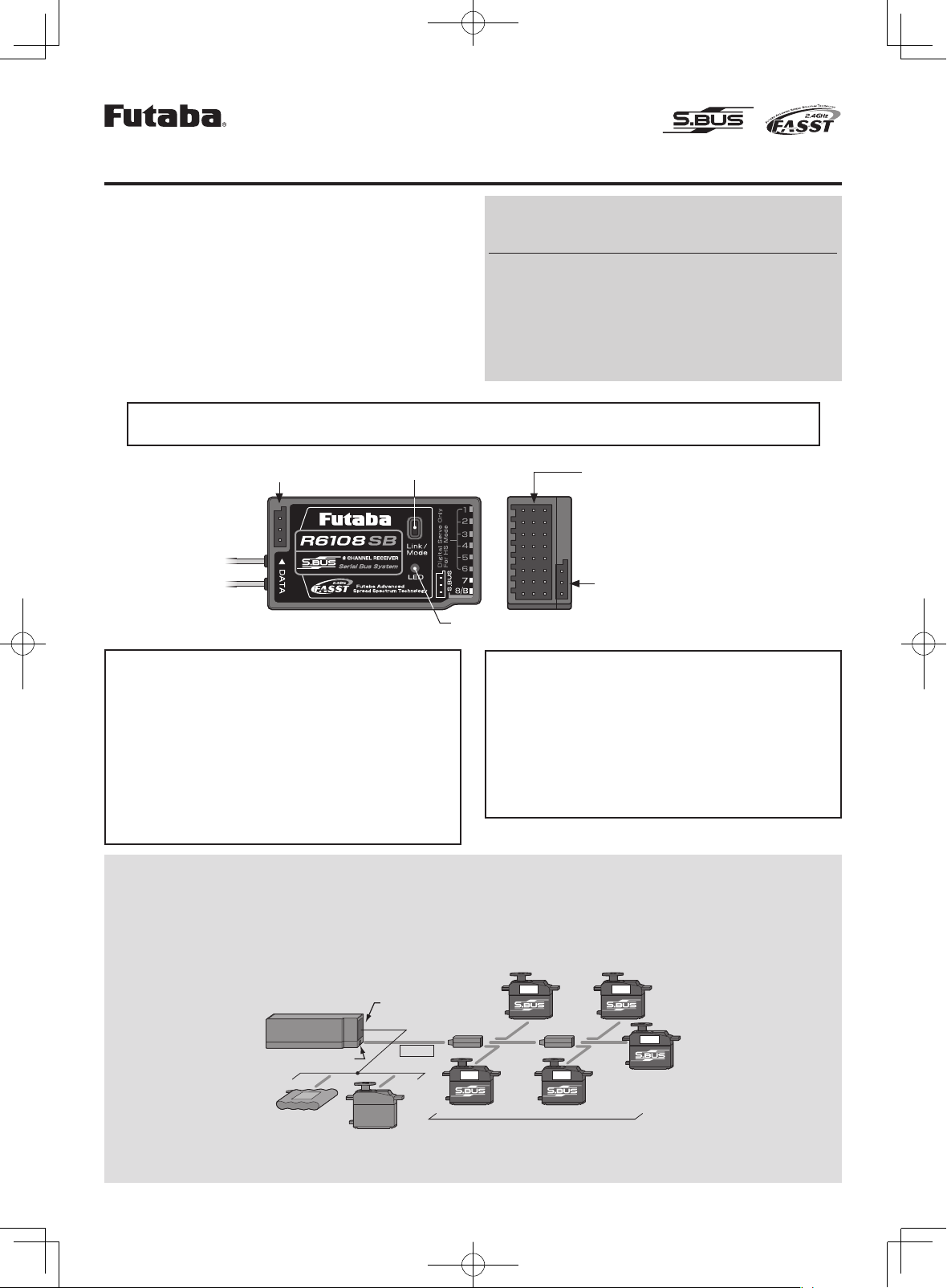
Link/Mode
switch
LED
R6108SB
DATA
port
• Channel outputs for conventional
system (1 to 8)
• Battery terminal (B)
•
S.BUS
Port (
S.BUS
)
What is S.BUS?
Different from conventional radio control systems the
S.BUS
system uses data communication to transmit control signals
from a receiver to a servo, gyro, or other
S.BUS
compatible
device. This data includes commands such as “move the
channel 3 servo to 15 degrees, move the channel 5 servo to
30 degrees” to multiple devices. The
S.BUS
devices execute
only those commands for their own set channel. For this
reason, it can be used by connecting multiple servos to the
same signal line.
[Connection by S.BUS system]
S.BUS hub S.BUS hub
S.BUS output
S.BUS
Ch output/
Battery terminal
R6108SB
Battery
S.BUS servo
Conventional
servo
2ch 4ch
3ch 5ch
6ch
*
Can also be used together with conventional servos.
Page 2
S.BUS Servo Channel Setting Method
S.BUS
servo channel setting can be performed at the
R6108SB
receiver.
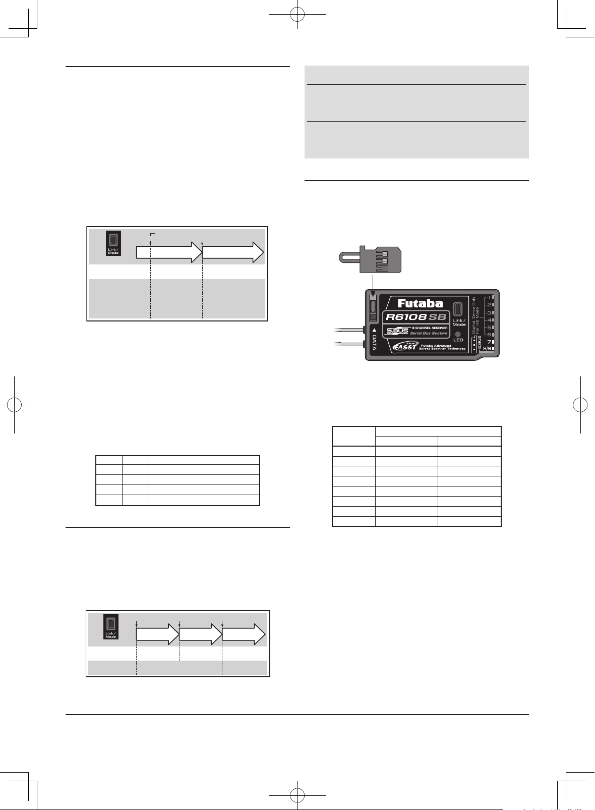
1
Connect the accessory short-plug to the
DATA
port of
the receiver.
Short-plug
(accessory)
* Connect the short-plug to the DATA port only when an S.BUS servo
channel is set. Normally do not connect the plug.
2
Connect an
S.BUS
servo to the conventional system
output connector(1 to 8) corresponding to the channel
you want to set.
Output
connector
Channel setting
Mode A Mode B
1 1 9
2 2 10
3 3 11
4 4 12
5 5 13
6 6 14
7
7 15
8 8
16
* Channel setting mode A (ch1 to 8 setting mode) or channel setting
mode B (ch9 to 16 setting mode) can be set.
3
Turn on the receiver.
* At once when turning on the receiver, the channel setting is com-
pleted in mode A.
(To switch to mode B, press the
Link/Mode
button until
the red and green
LED
starts to blink simultaneously.
The channel setting is completed in mode B.)
* The LED corresponding to the setting mode blinks.
Mode A: Red blinks 3 times
Mode B: Green blinks 3 times
4
Turn off the receiver.
Operation Mode Select
The operation mod e is on "Norma l mode" from factor y
shipping. When to change the mode, please follow the steps
shown below.
1
Turn off the receiver.
2
Press and hold the
Link/Mode
switch and turn on the
receiver. Keep the switch hold more than one(1)
second. The
LED
starts flas hing wi th the current
status.
3
Release the switch.
4
Turn off the receiver.
By doing this step, the mode can switch over between two(2)
modes.
0 to 1 sec. More than 1 sec.
0 sec. 1 sec.
Press and Hold
Turn on the receiver.
No function
Showing the CURRENT
mode with blink.
Red Blink = Normal
Green/Red Blink =
High Speed
Solid as the mode changed.
Red Solid = Normal
Green/Red Solid = High
Speed
(Become Red after one (1)
second)
(Function)
To change the mode between
Normal and High Speed
(LED
Status)
Please check the operation mode by observing the
LED
when
turning on the receiver. If possible there's no
FASST
transmitter
turned on around you in order to make rmer check.
When turn on the receiver, the
LED
will be;
• Red when on "Normal mode"
• Green and Red (makes Orange) when on "High Speed mode".
(After two(2) seconds, change to Red.)
If there are some
FASST
transmitter turned on around the
receiver, the
LED
may show the above status for a brief
moment then changed to the status indication as shown in the
"
LED
indication" table.
LED Indication
Green Red Status
Solid Solid Initializing
Off Solid No signal reception
Solid Off Receiving signals
Blink Off Receiving signals but ID is unmatched
Link to the transmitter
1
Press and hold the
Link/Mode
switch more than two(2)
seconds.
Re-adjust the F/S position (only for TM-8)
1
Press and hold the
Link/Mode
switch between one(1)
and two(2) seconds.
0 to 1 sec. 1 to 2 sec. More than 2 sec.
0 sec. 1 sec. 2 sec.
Press and Hold
No function
With TM-8
(not included in this set)
To set the F/S
position(No re-link)
Re-link(ID set) and to
set the F/S position
No function
Other than TM-8
(not included in this set)
Re-link(ID set)
WARNING
Do not pe rfor m the linking procedure with
motor's main wire is connected or the engine is
operating as it may result in serious injury.
While the linking is done, please cycle receiver
power and check if the receiver to be linked is
really under the control by the transmitter to be linked.
FUTABA CORPORATION
1080 Yabutsuka, Chosei-mura, Chosei-gun, Chiba-ken, 299-4395, Japan
Phone: +81 475 32 6982, Facsimile: +81 475 32 6983
1M23N17424 ©FUTABA CORPORATION 2010, 1 (1)
 Loading...