

Page 1
1M23N34102
T-FHSS Air 2.4GHz System
S.BUS2 port and 4 channels for conventional system
R3004SB
Thank you for purchasing a Futaba R3004SB T-FHSS Air-2.4GHz compatible receiver. The R3004SB receiver features bidirectional communication with a T-FHSS Air-2.4GHz Futaba transmitter using the S.BUS2 port. Using the S.BUS2 port an
impressive array of telemetry sensors may be utilized.
Small size, Light weight Receiver
Applicable systems: Futaba T-FHSS Air 2.4GHz system
Usage precaution
• Futaba T-FHSS Air system does not work with current Futaba
FASST/FASSTest/S-FHSS/T-FHSS Car system. Futaba FASST/
FASSTest/S-FHSS/T-FHSS Car system and T-FHSS Air system
are not compatible to each other.
WARNING
Wrap the receiver with something soft, such as foam
rubber, to avoid vibration. Moreover, the receiver must
not get wet.
Do not short-circuit the connectors.
Do not expose the receiver to high temperatures.
• The shrink cover could become distorted.
Do not break the tube.
• Could cause a short circuit.
When inserting and removing a connector, hold the
receiver tightly.
• Be careful so that a tube doesn't come off.
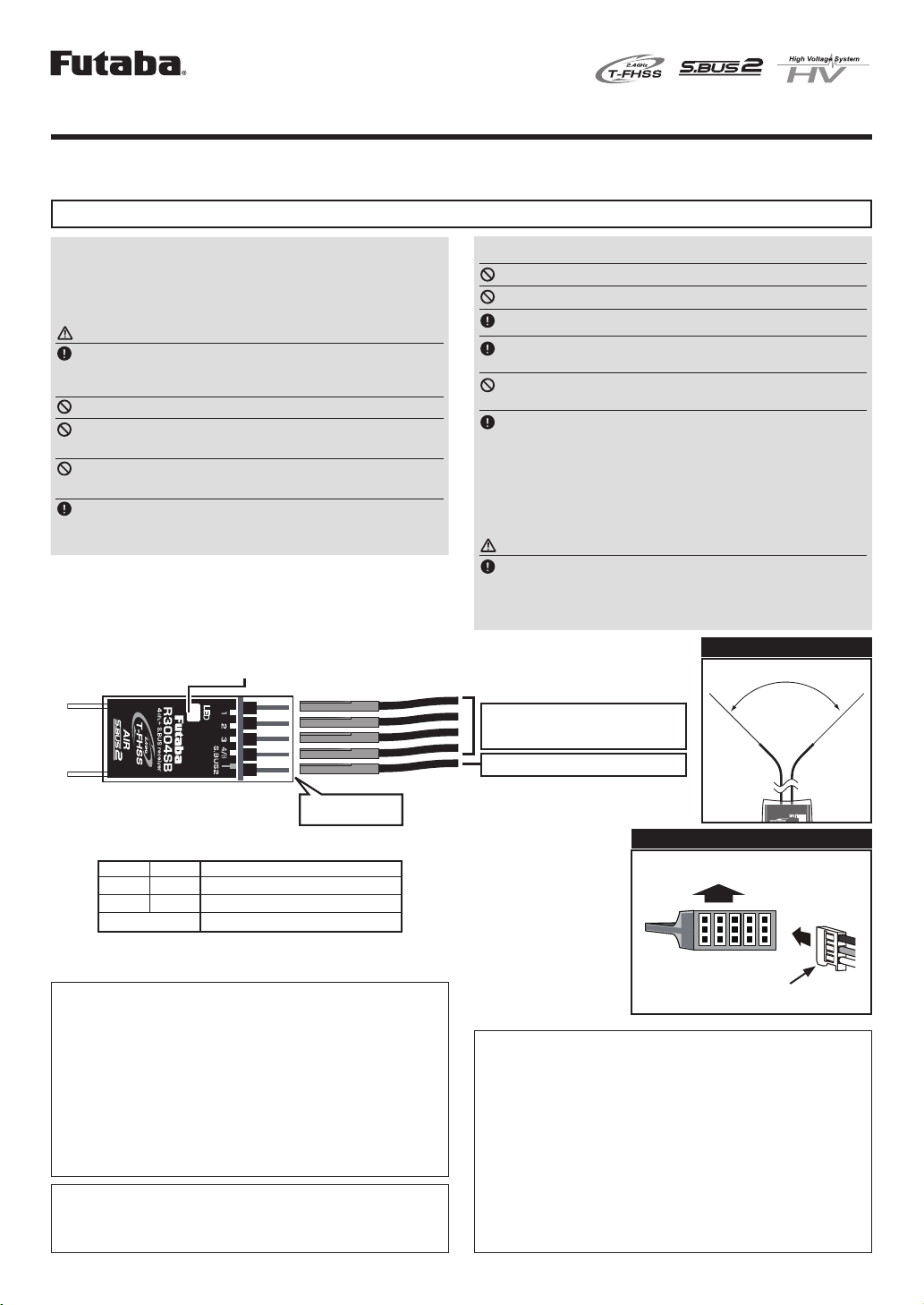
The receiver power
supply can be
connected to any port.
Antenna
R3004SB
LED
Antenna installation precaution
Do not cut or bundle the receiver antenna wire.
Do not bend the coaxial cable. It causes damage.
The antenna should not be pulled.
Keep the antenna as far away from the motor, ESC
and other noise sources as you possibly can.
Do not touch the antenna to metal, carbon, or other
conductive material.
Be sure that the two antennas are placed at 90 de-
grees to each other.
• The R3004SB has two antennas. In order to maximize signal reception and promote safe modeling Futaba has adopted a diversity antenna system. This allows the receiver to obtain RF signals on both
antennas and fly problem-free.
Antenna installation for carbon fuse
WARNING
The antenna portion of 30mm tip must be fully ex-
posed.
• Please make sure that the exposed portion won't slide back in the
fuse due to wind pressure or other force during the flight session.
Antenna installation
90˚
CH1-CH4 output
conventional system Port
S.BUS2 equipment
Please refer the table below for
LED status vs receiver's condition.
S.BUS2 Port
LED Indication
Green Red Status
Off Solid No signal reception
Solid Off Receiving signals
Alternate blink Unrecoverable error (Memory, etc.)
Compliance Information Statement (for U.S.A.)
This device, trade name Futaba Corporation, model number R3004SB, complies with
part15 of the FCC Rules. Operation is subject to the following two conditions:
(1) This device may not cause harmful interference, and
(2) This device must accept any interference received, including interference that may
cause undesired operation.
CAUTION: To assure continued FCC compliance
1. Any changes or modications not expressly approved by the grantee of this device
could void the user's authority to operate the equipment.
2. This equipment complies with FCC radiation exposure limits set forth for an
uncontrolled environment.
This equipment should be installed and operated with minimum distance 20cm between
the radiator & your body.
The responsible party of this device compliance is:
Futaba Service Center
3002 N Apollo Drive Suite 1, Champaign, IL 61822 U.S.A.
TEL (217)398-8970 or E-mail: support@futaba-rc.com (Support)
Declaration of Conformity (for EU)
Hereby, Futaba Corpor ation decla res that th e radio equipment typ e is R3004SB i n compliance wi th Direct ive 2014/53/E U. The full te xt of the EU decla ration of con formity is available at the fol lowing int ernet add ress:
http://www.rc.futaba.co.jp/english/dl/declarations.html
Direction of the connectors
Upper Side (Label)
Receiver
Tags are downwards
Compliance Information Statement (for Canada)
This d evice complie s with Indu stry Ca nada license-exemp t RSS stand ard(s). Operat ion is
subject to the followi ng two condit ions: (1) this device m ay not cause in terferen ce, and (2)
this de vice must ac cept any int erferenc e, includi ng interfe rence that m ay cause und esired
oper ation of the d evice. Th is equipm ent complie s with IC ra diation exposure limits s et
forth fo r an uncont rolled envi ronment. T his equip ment should be i nstalle d and opera ted
with minimum d istance 20 cm betwee n the radiat or & your body.
Fren ch: Cet ap parei l radio e st conf orme au C NR-210 d’Indus trie C anad a. L’utilis ation
de ce d isp osit ifes t auto ris ée seu leme nt au x deux c ond itio ns sui vant es : (1) il ne do it
pas pro duire de br ouillage, e t (2) l’uti lisateu r du dispositif doit êtr e prêt à acce pter tout
broui llage radio électriq ue reçu, même sice brouil lage est susc eptible de co mpromett re le
fonctio nnement du d ispositi f. Cet équipe ment est con forme aux li mites d’exposit ion aux
rayonn ements IC établies pour u n environ nement non cont rôlé.
Cet équ ipement est c onforme au x limite s d’expo sition aux rayo nnement s IC établies po ur
un envi ronneme nt non contrôl é. Cet équipe ment doit êtr e install é et utilisé ave c un mini
mum de 20 c m de distance entre la sou rce de rayonnement et votre co rps.
-
Page 2
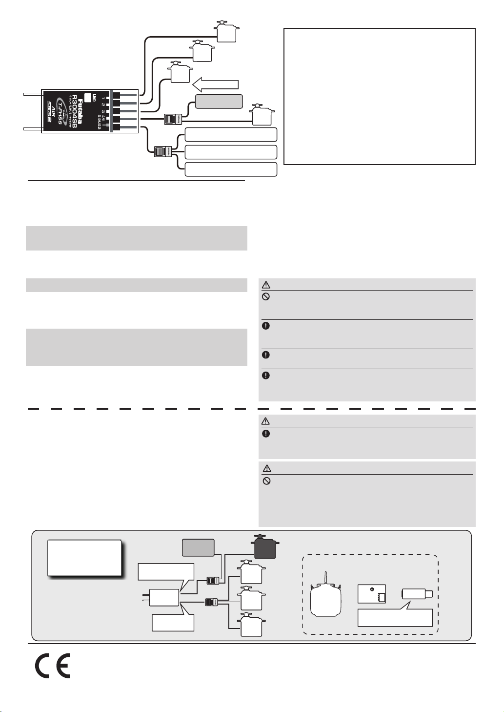
CH1
e.g. Telemetry system
HUB
HUB
CH2
CH3
Power supply
Battery
Futaba Telemetry Sensor
Futaba Telemetry Sensor
Futaba Telemetry Sensor
Link to the transmitter
Easy Link ID allows T-FHSS Air receivers to link to
compatible transmitter without pressing the link button on the
receiver.
Bring the transmitter and the receiver close to each
1
other, within 20 inches (half meter).
Turn on the transmitter. Place the transmitter into the
2
receiver linking mode.
Turn on the receiver.
3
The receiver will wait for the linking process to begin
4
for 3 seconds. Following that it will return to the
normal operation mode.
When the LED of the receiver changes from blinking
5
red to solid green, linking is completed.
(A link waiting state is ended in 3 second.)
* Refer to the transmitters operation manual for complete details on how
to place the transmitter into the linking mode.
R3004SB Specications
T-FHSS Air 2.4GHz system/S.BUS2 port and 4 channels for
conventional system receiver
• Dual antenna diversity
• Size: 0.71 x 1.63 x 0.39 in. (18.0 x 41.4 x 9.9 mm)
• Weight: 0.17 oz. (4.8g)
• Power requirement: 4.8V to 7.4V
• Battery F/S Voltage: It sets up with a transmitter
• Frequency band: 2.4GHz band
CH4
* If there are many T-FHSS Air systems turned on in close proximity,
* If the System Type of the transmitter is changed, the receiver will need
* Link is required when a new model is made from a model selection.
• RF power output: 25mW EIRP
* Be sure that when using ESC's regulated output the current capac-
ity of the ESC meets your usage condition.
* S.BUS2 port: R3004SB can be used with up to 18 channels. How-
ever, it differs according to the transmitter. An unused channel is
a neutral signal. The F/S setting channel at F/S is F/S position
Another, it is Hold signal.
your receiver might have difficulty establishing a link to your transmitter. This is a rare occurrence. However, should another T-FHSS Air
transmitter/receiver be linking at the same time, your receiver could
link to the wrong transmitter. This is very dangerous if you do not notice this situation. In order to avoid the problem,we strongly recommend you to double check whether your receiver is really under control by your transmitter.
to be re-linked to the transmitter.
.
WARNING
Do not perform the linking procedure while the mo-
tor's main wire connected or the engine is operating as it
may result in serious injury.
When the linking is complete, please cycle the receiver power and ensure the receiver is properly linked to the
transmitter.
Please power up your system in this order. Transmitter first, followed by the receiver.
If the R3004SB receiver was previously linked to another transmitter, make sure that transmitter is not operating while linking the receiver to the new transmitter.
What is S.BUS2?
Different from conventional radio control systems, the
S.BUS2 system uses data communication to transmit control
signals from a receiver to a servo, gyro, or other S.BUS2
compatible devices. This data includes commands such as
“move the channel 3 servo to 15 degrees, move the channel 5
servo to 30 degrees” to multiple devices. The S.BUS2 devices
execute only those commands for their own set channel. For
this reason, it can be used by connecting multiple servos to
the same signal line. S.BUS devices can not be connected to
S.BUS2 port.
Connection
by S.BUS2
system
CH1-4:
Conventional Ports
R3004SB
Receiver
S.BUS2 Port
oak kandakajicho 8F 3-4 Kandakajicho, Chiyoda-ku, Tokyo 101-0045, Japan
Battery
Hub
Hub
FUTABA CORPORATION
TEL: +81-3-4316-4820, FAX: +81-3-4316-4823
WARNING
Turn on the power on transmitter → receiver in order.
In addition, always check the operation of all the functions before flight.
WARNING
Do not insert or remove the S.BUS2 connector while
the receiver power is ON.
Since the S.BUS2 servo switches the operation mode automatically
according to the type of signal (S.BUS2 signal/PWM signal) from the receiver, if the connector is inserted or removed while the power is ON, an
S.BUS2 connected servo will be erroneously recognized and may stop.
●Can also be used together with conventional servo.
S.BUS servo CH setting device
Transmitter
with S.BUS
setting
or or
SBC-1
Drivers and Link programs
"S-Link" must be installed.
©FUTABA CORPORATION 2017, 12 (1)
(1-4 channels)
CIU-2/3
S.BUS2
Servo
S.BUS2
Servo
S.BUS2
Servo
Conventional
Servo
 Loading...