

Page 1

Applicable systems: Futaba T-FHSS Air 2.4GHz system
LED Indication
LED Status
Solid Receiving signals
1 time blink Waiting for link
2 times blink No signal reception
2 times blink
(Every 4 seconds)
Unrecoverable error (Memory, etc.)
Antenna installation precaution
Do not cut or bundle the receiver antenna wire.
Do not bend the coaxial cable. It causes damage.
The antenna should not be pulled.
Keep the antenna as far away from the motor, ESC
and other noise sources as you possibly can.
Do not touch the antenna to metal, carbon, or other
conductive material.
Be sure that the two antennas are placed at 90 de-
grees to each other.
• The R3004SB has two antennas. In order to maximize signal reception and promote safe modeling Futaba has adopted a diversity antenna system. This allows the receiver to obtain RF signals on both
antennas and fly problem-free.
Antenna installation for carbon fuse
WARNING
The antenna portion of 30mm tip must be fully ex-
posed.
• Please make sure that the exposed portion won't slide back in the
fuse due to wind pressure or other force during the flight session.
Usage precaution
• Futaba T-FHSS Air system does not work with current Futaba
FASST/FASSTest/S-FHSS/T-FHSS Car system. Futaba FASST/
FASSTest/S-FHSS/T-FHSS Car system and T-FHSS Air system
are not compatible to each other.
WARNING
Wrap the receiver with something soft, such as foam
rubber, to avoid vibration. Moreover, the receiver must
not get wet.
Do not short-circuit the connectors.
Do not expose the receiver to high temperatures.
• The shrink cover could become distorted.
Do not break the tube.
• Could cause a short circuit.
When inserting and removing a connector, hold the
receiver tightly.
• Be careful so that a tube doesn't come off.
Please refer the table below for
LED status vs receiver's condition.
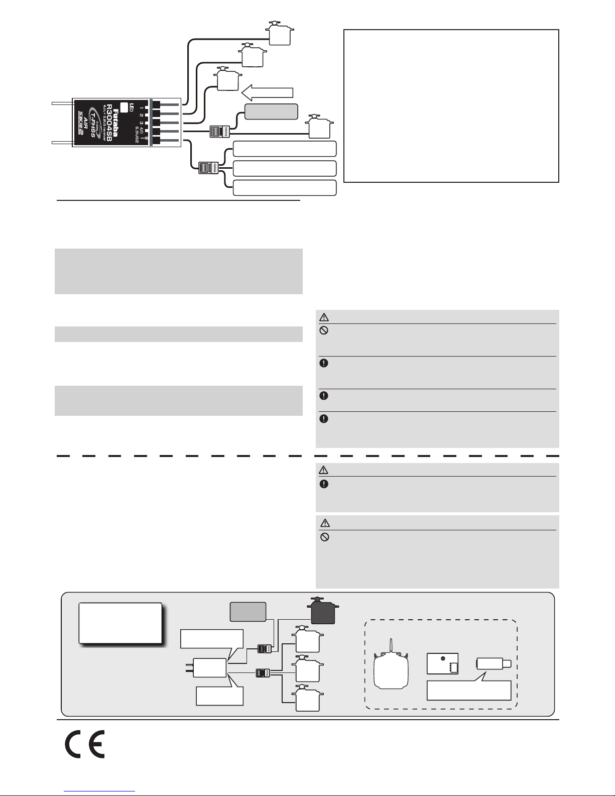
1M23N34104
R3004SB
Antenna
S.BUS2 Port
CH1-CH4 output
conventional system Port
LED
S.BUS2 equipment
Direction of the connectors
90˚
Antenna installation
R3004SB
T-FHSS Air 2.4GHz System
S.BUS2 port and 4 channels for conventional system
Small size, Light weight Receiver
Thank you for purchasing a Futaba R3004SB T-FHSS Air-2.4GHz compatible receiver. The R3004SB receiver features bidirectional communication with a T-FHSS Air-2.4GHz Futaba transmitter using the S.BUS2 port. Using the S.BUS2 port an
impressive array of telemetry sensors may be utilized.
The receiver power
supply can be
connected to any port.
Receiver
Tags are downwards
Upper Side (Label)
Declaration of Conformity (for EU)
Hereby, Futaba Corp oration declares t hat the ra dio equipment type is R3004SB in compliance with Directive 2014/53/EU. The fu ll text of the EU declaration of confo rmity is available at the following internet addres s:
http://www.rc.futaba.co.jp/english/dl/declarations.html
Compliance Information Statement (for Canada)
This d evice compl ies with I ndustr y Canada license-exempt RSS stan dard(s). Oper ation is
subject to the following two conditions: (1) this device may not c ause interference, and (2)
this device must a ccept any interfe rence, including i nterfe rence that may cause u ndesired
oper ation of the device. This eq uipment complies with IC ra diatio n exposu re lim its set
forth for an uncontrolled e nviron ment. Th is equipment should be i nstal led and ope rated
with minimu m distance 20cm between the radiator & your body.
Fren ch: Cet a ppar eil ra dio est confo rme au C NR-210 d’Indu str ie Can ada. L’uti lisa tion
de ce d isposi tif est a utoris ée se ulement a ux deux c onditio ns su iva nte s : (1) il ne doi t
pas pro duire de brouill age, et (2) l’utilisateur du dispositif doit êt re prêt à accepter tout
broui llage rad ioélect rique reçu, même sice brouillage est susceptible de compromet tre le
fonctionnement du dispositif. Cet équipement est conforme aux limites d’exposition aux
rayonnements IC établies po ur un environne ment non contrôlé.
Cet équ ipement est confor me aux limites d’exposit ion aux rayonnement s IC établie s pour
un environne ment non contrôlé. Cet équipement doit être i nstallé et utilisé avec un mi ni
-
mum de 20 c m de dista nce entr e la source d e rayonnement et votre corps.
Compliance Information Statement (for U.S.A.)
This device, trade name Futaba Corporation, model number R3004SB, complies with
part15 of the FCC Rules. Operation is subject to the following two conditions:
(1) This device may not cause harmful interference, and
(2) This device must accept any interference received, including interference that may
cause undesired operation.
CAUTION: To assure continued FCC compliance
1. Any changes or modications not expressly approved by the grantee of this device
could void the user's authority to operate the equipment.
2. This equipment complies with FCC radiation exposure limits set forth for an
uncontrolled environment.
This equipment should be installed and operated with minimum distance 20cm between
the radiator & your body.
The responsible party of this device compliance is:
Futaba Service Center
3002 N Apollo Drive Suite 1, Champaign, IL 61822 U.S.A.
TEL (217)398-8970 or E-mail: support@futaba-rc.com (Support)
Page 2
WARNING
Do not insert or remove the S.BUS2 connector while
the receiver power is ON.
Since the S.BUS2 servo switches the operation mode automatically
according to the type of signal (S.BUS2 signal/PWM signal) from the receiver, if the connector is inserted or removed while the power is ON, an
S.BUS2 connected servo will be erroneously recognized and may stop.
WARNING
Turn on the power on transmitter → receiver in order.
In addition, always check the operation of all the functions before flight.
e.g. Telemetry system
What is S.BUS2?
Different from conventional radio control systems, the
S.BUS2 system uses data communication to transmit control
signals from a receiver to a servo, gyro, or other S.BUS2
compatible devices. This data includes commands such as
“move the channel 3 servo to 15 degrees, move the channel 5
servo to 30 degrees” to multiple devices. The S.BUS2 devices
execute only those commands for their own set channel. For
this reason, it can be used by connecting multiple servos to
the same signal line. S.BUS devices can not be connected to
S.BUS2 port.
Futaba Telemetry Sensor
Futaba Telemetry Sensor
Futaba Telemetry Sensor
HUB
HUB
Power supply
Battery
CH4
CH3
CH1
CH2
R3004SB Specications
T-FHSS Air 2.4GHz system/S.BUS2 port and 4 channels for
conventional system receiver
• Dual antenna diversity
• Size: 0.71 x 1.63 x 0.39 in. (18.0 x 41.4 x 9.9 mm)
• Weight: 0.17 oz. (4.8g)
• Power requirement: 4.8V to 7.4V
• Battery F/S Voltage: It sets up with a transmitter
• Frequency band: 2.4GHz band
• RF power output: 25mW EIRP
* Be sure that when using ESC's regulated output the current capac-
ity of the ESC meets your usage condition.
* S.BUS2 port: R3004SB can be used with up to 18 channels. How-
ever, it differs according to the transmitter. An unused channel is
a neutral signal. The F/S setting channel at F/S is F/S position
.
Another, it is Hold signal.
Link to the transmitter
Easy Link ID allows T-FHSS Air receivers to link to
compatible transmitter without pressing the link button on the
receiver.
1
Bring the transmitter and the receiver close
to each other, within 20 inches (half meter).
2
Turn on the transmitter. Place the transmitter into the receiver linking mode.
3
Turn on the receiver.
4
The receiver will wait for the linking process to begin for 5 seconds. Following that
it will return to the normal operation mode.
5
When the link is completed, the LED on
the receiver changes to solid.
* Refer to the transmitters operation manual for complete details on how
to place the transmitter into the linking mode.
WARNING
Do not perform the linking procedure while the mo-
tor's main wire connected or the engine is operating as it
may result in serious injury.
When the linking is complete, please cycle the receiver power and ensure the receiver is properly linked to the
transmitter.
Please power up your system in this order. Transmitter first, followed by the receiver.
If the R3004SB receiver was previously linked to another transmitter, make sure that transmitter is not operating while linking the receiver to the new transmitter.
* If there are many T-FHSS Air systems turned on in close proximity,
your receiver might have difficulty establishing a link to your transmitter. This is a rare occurrence. However, should another T-FHSS Air
transmitter/receiver be linking at the same time, your receiver could
link to the wrong transmitter. This is very dangerous if you do not notice this situation. In order to avoid the problem,we strongly recommend you to double check whether your receiver is really under control by your transmitter.
* If the System Type of the transmitter is changed, the receiver will need
to be re-linked to the transmitter.
* Link is required when a new model is made from a model selection.
Battery
S.BUS2 Port
CH1-4:
Conventional Ports
R3004SB
Receiver
Hub
Hub
●Can also be used together with conventional servo.
S.BUS2
Servo
S.BUS2
Servo
S.BUS2
Servo
Conventional
Servo
Connection
by S.BUS2
system
Transmitter
with S.BUS
setting
S.BUS servo CH setting device
SBC-1
CIU-2/3
or or
Drivers and Link programs
"S-Link" must be installed.
(1-4 channels)
FUTABA CORPORATION
oak kandakajicho 8F 3-4 Kandakajicho, Chiyoda-ku, Tokyo 101-0045, Japan
TEL: +81-3-4316-4820, FAX: +81-3-4316-4823
©FUTABA CORPORATION 2018, 3 (2)
 Loading...