

Page 1
Futaba
DIGITAL PROPORTIONAL
RADIO CONTROL
FP-7UAP
PCM 1024 SYSTEM
FP-7UAF
FM SYSTEM
D60460
Page 2
a Futaba digital proportional radio control set.
Please open it when reading this manual.
• FEATURES
• High resolution and fast response
Thank you for purchasing
Please read this manual
carefully before using your set
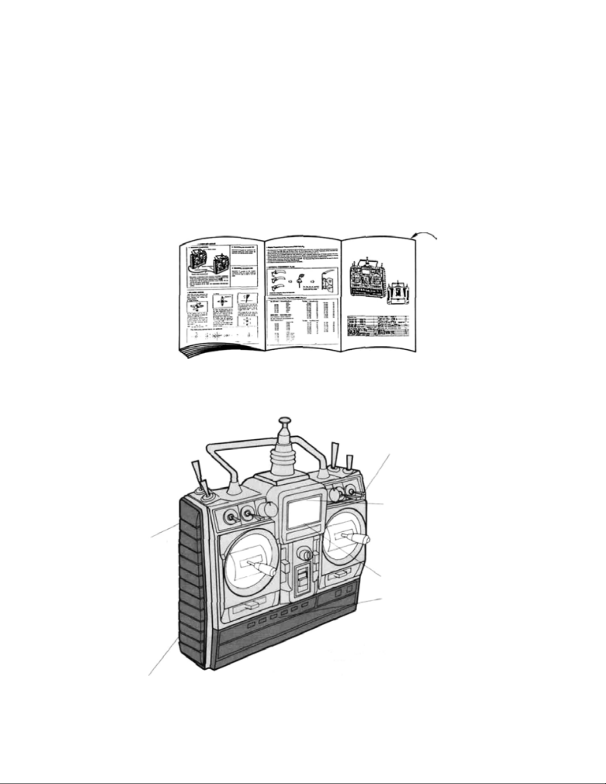
The last page of this manual
is a double foldout showing the name
of each part of the transmitter.
PCM 1024 system (FP-7UAP)
FM system (FP-7UAF)
7 channels system
foldout
• RF module
• Trainer system
(Trainer cable optional)
Dual rate switch
w/combination function
• Normal display mode
• Error display mode
• Edit display mode
Liquid crystal panel
displays all the
information necessary
in each display mode.
Six edit keys provide
fo r easy data setting.
• Set data is not lost
even when the battery is changed.
• Complete mixing functions
—Snap-roll!
4 channels
—Flaperon & aileron differential -Programmable mixing 2 separate systems
—Flap -> elevator mixing
—Elevator
->
flap
mixing
Page 3

• TABLE OF C ONTENTS
SET CONTENTS ...........................................
BEFORE USING ..........................................
DISPLAY FUNCTIONS
NORMAL DISPLAY
ERROR
EDIT
FUNCTIONS AND DATA SETTING
ADJUSTABLE TRAVEL
DUAL
EXPONENTIAL........................................ 9
REVERSE
FAIL
PROGRAMMABLE MIXING 1
PROGRAMMABLE MIXING 2 ............................
ELEVATOR -> FLAP MIXING ............................
FLAP -> ELEVATOR MIXING ............................
SNAP-ROLL
AILERON
FLAPERON ...........................................
FLAP TRIM ...........................................
SUB
COMBINATION SWITCH
MODULATION ........................................
OTHER FUNCTIONS ....................................
USING THE ACCESSORIES ...............................
NOMENCLATURE (DOUBLE FOLDOUT) ......................
SERVO EXPLODED VIEW ...................................
DISPLAY
DISPLAY
RATE
SAFE
TRIM.............................................18
..........................................
............................................
...........................................
..........................................
DIFFERENTIAL
MODE
MODE
MODE
..............................
................................
..................................
VOLUME
................................
........................
............................
..............................
2
3-5
6
7
7
8
8
9
10
11
12
13
14
15
16
17
18
18
19
19-20
20-21
22
23
ABBREVIATIONS
ATV
D/R DUAL RATE STRM SUB TR I M
EXP EXPONENTIAL COMB COMBINATION SWITCH
REV REVERSE MOD MODULATION
F/S FAILSAFE AUX AUXILIARY
PMX PROGRAMMABLE MIXING PCM PULSE CODE MODULATI
2->6 ELEVATOR^ FLAP MIXING PPM PULSE POSITION
6->2 FLAP -> ELEVATOR MIXING MODULATION
SNP SNAP-ROLL B.F/S BATTERY FAIL SAFE
DIFF AILERON DIFFERENTIAL
ADJUSTABLE TRAVEL FLPR FLAPERON
VOLUME FLTR FLAP TRIM
—1
—
Page 4

• SET CONTENTS
FP-7UAP
• FP-T7UAP ( X1 )
• FP-TP-FM (X1 )
*Specifications are subject to change without prior notice.
FP-7UAF
• FP-T7UAF (X1)
2 st ic ks , 7 channels, PCM or FM transmitter
Transmitting frequency: 72MHz, 50MHz,
35/36MHz, 40/41 MHz or 29MHz band
Modulation: FM-PCM/PPM Selectable
Power requirement: 9.6V Nicd battery pack
Current drain: 200mA
Rating
• FP-R129DP (X1)
(Dual Conversion Type)
or FP-R137GP (X1)
• FP-S148 (X4)
or FP-S3001 (X4)
•
NT-8LP(X1)
• FP-R128DF (X1)
(Dual Conversion Type)
Receiving frequency: 72MHz, 50MHz,
35/36MHz, 40/41 MHz or 29MHz band
Intermediate frequency: 1st IF 10.7MHz,
2nd IF 455kHz (R129DP, R128DF), 455kHz
(R137GP)
Power requirement; 4.8V Nicd battery pack
Current drain: 35mA (R129DP),
26mA (R128DF), 25mA (R137GP)
Dimensions: 63.0x37.8x24.1mm (R129DP).
63.8x35.4x20.3mm (R128DF) (excluding
protruding parts), 57x42x24mm (R137GP)
Weight: 45g (R129DP),40g (R128DF ),
45g(R137GP)
Receiving range: 500m on the ground. 1000m
in the air (range differs with the surroundings]
Control system: + pulse widt h control
Operating angle: Rotary system, one side 45
or greater (including trim)
Power requirement: 4.8V or
with receiver)
Current drain: 8mA at 6V (at idle)
Output torque; 3kg/cm
Operating speed; 0.22sec/60°
Dimensions: 40.4x1 9.8x36mm
Weight: 44.4g, 1.56oz. (S148),
45.1q, 1.59oz. (S3001)
Voltage: 9.6V
Capacity: 800mAh
(shared wi th servo)
6.0V (shared
• NR-4J (X1)
• Charger
• FM crystal set (Transmitter and Receiver)
However use the following crystal types for dual conversion receiver (R129DP, R128DF).
The set does not include t he following:
• Trainer cable (6-conductor)
• Receiver switch
• Servo horn
• Servo tray
• Tx hook band
• Frequency flag
or ribbon
- 2
-
Voltage: 4.8V
Capacity: 500mAh
Dimensions: 51x58x1 5mm
Weight: 95g,3.35oz.
Page 5
• BEFORE USING
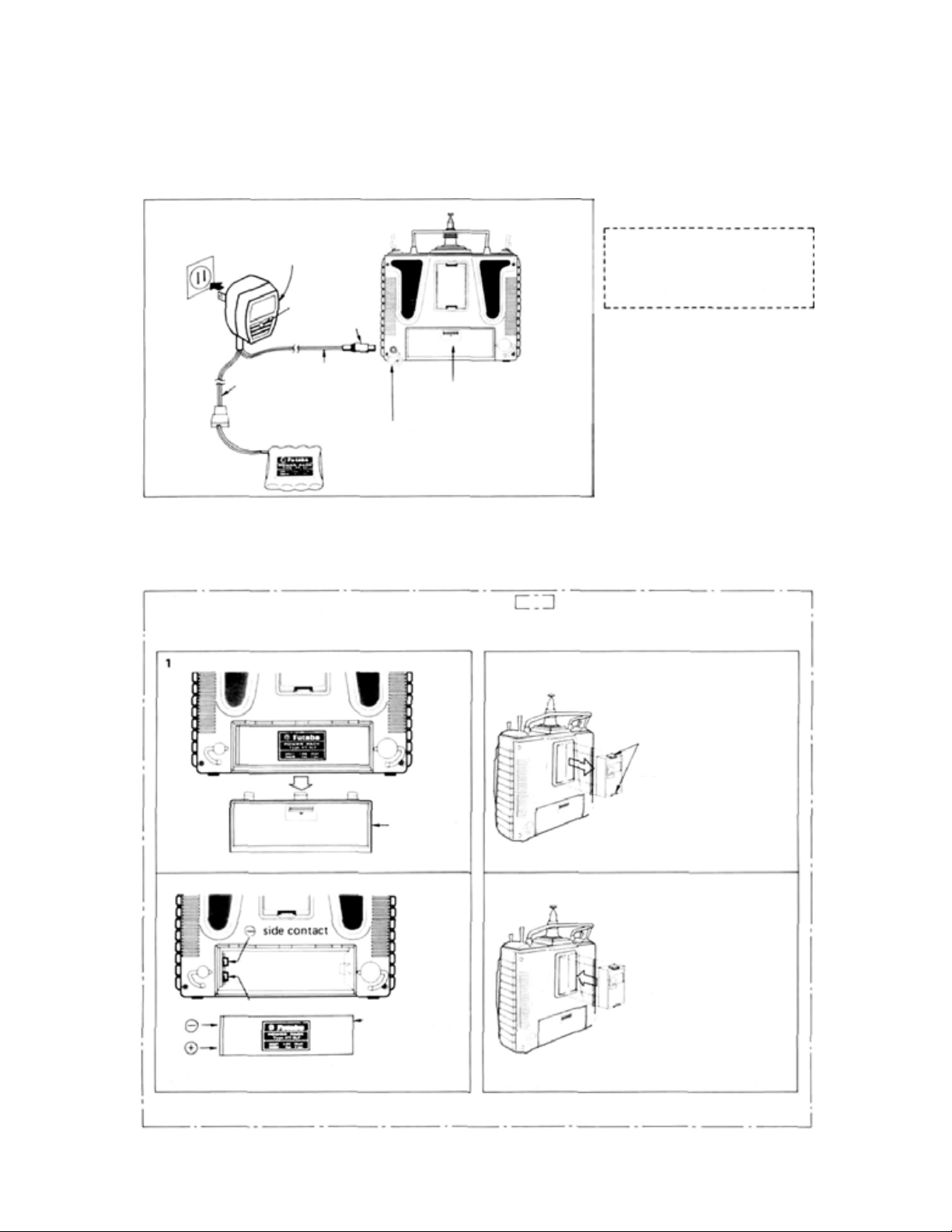
• Charging the transmitter and receiver Nicd battery
FP-7UAPor FP-7UAF
Charger
LED
Power plug
Rx side
Male
Female
• Factory setting of transmitter modulation system
The transmitter modulation system (PCM/PPM mode) is switched by
data setting. (For the setting method, see P19.). However, it is set as
follows at the factory:
FP-T7UAP ..... PCM mode FP-T7UAF ..... PPM mode
Refer to only the necessary items of the items enclosed in
• Changing the transmitter Nicd battery
Remove the battery cover.
Tx side
Receiver
Nicd battery NR-4J
(NT-8LP inside)
Remove the charging cap
and connect the charger.
pack
• Changing the R F module to change the
frequency band
1 Remove the RF module.
*Use the special Futaba charger.
• The charging time is 15 hours.
[However when the battery was
not used fo r some time , charge and
discharge it 2 — 3 times. Otherwise,
the battery will not be charged even
after t h e specified charging time !
A fully-charged transmitter battery
can be used for about 10 flights of
10 minutes each. The airborne NR4J Nicd battery pack can be used
for about 6 flights when 6 servos
are used.
Notes: (PBC-8B)
1) First, connect to
red lamp goes on.
2) Then, connect to RX Nicad after
connecting, L, E, D, changes
color from red to greenish red
(orange) which indicates that
both TX and RX Nicads are
being charged.
3) In case of separate charging, L,
E, D, color wil l be:
RX Nicad - Green
TX Nicad- Red
TX Nicad and
Battery cover
2 Change the Nicd battery.
® side contact
*Load the battery while paying careful attention to
the direction of the contacts.
-Nicd battery
(Only the NT-8LP
can be used.)
—3—
Pull the RF module forward
while pressing these tabs to
the inside
2 Change the RF module.
Push in the new module,
while being careful not to
bend the pins, until the tabs
at
both
sides
lock
into
with a "click".
*Use the special FP-TP-FM RF module for the FP-
7UAP and 7UAF. Other RF modules cannot be used.
•When the transmitter frequency band is changed,
receiver frequency band must be changed also.
place
the
Page 6
• BEFORE USING
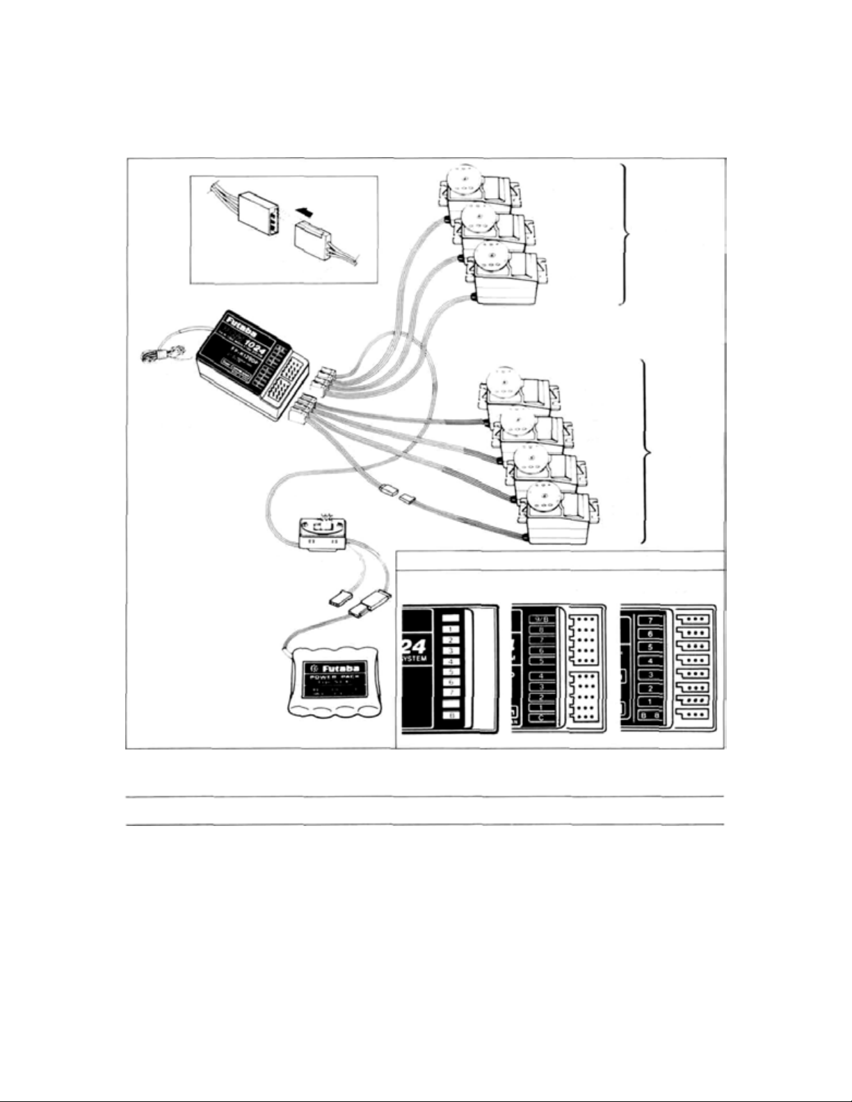
• RECEIVER AND SERVO CONNECTIONS
CH7 (A UX)
Pay careful attention to the
polarity of the connector.
Antenna
wire
PCM receiver
FP-R129DP, FP-R137GPor
FM receiver FP-R-128DF
Charging jack
Extension cord
Receiver switch
FP-R137GP
servo
CH2
Elevator
servo
CH1
Aileron
servo
Option
(sol d separately)
CH6 Flap servo
CH5
Landing gear
servo
CH4
Rudder
CH3
Throttle
servo
Receiver connector arrangement
FP-R129DP
Four servos
are supplied
as standard.
FP-R128DF
Nicd battery pack
NR-4J
PRECAUTIONS
• Connect the receiver, servos, switches, and battery as shown in the figure. Extend the transmitter and receiver antennas to their full
length.
•Turn
on the transmitter power
turn on the receiver power switch.
servos
will
go
to
The
their
Move the transmitter sticks one at a time to
check that each servo follows its control stick
movement.
switch,
neutral
then
position.
• Connect the pushrods to the servos and check
that the direction of travel of each servo
matches the direction of movement of its control
stick. If a servo
does
not
move
er direction, switch its direction with the servo
reversing function.
•
Operate
each
servo
horn
over its
full
check that the pushrod does not bind or is not
too loose. Unreasonable force applied to the
horn
will
servo
adversely
affect the
- 4 -
in the prop-
stroke and
servo
and
Page 7
• BEFORE USING
drain the battery pack very quickly. Make the
travel of each control mechanism somewhat
larger than the full stroke (including trim) of
the servo horn. Adjust the servo horns so that
they move smoothly even when the trim lever
and stick are operated simultaneously in the
same direction.
• Be alert for noise.
This set is noise-resistant, but not completely
immune to noise. The use of noiseless parts is
recommended.
•When installing the switch harness, cut a rectangular hole slightly larger than the full stroke
of the switch and install the switch so that it
moves smoothly from ON to OFF. Also do this
when the switch is installed inside the fuselage
and is turned on and off from the outside with
a piece of wire. Install the switch where it will
not be exposed to engine oil or dust and dirt.
• Although the antenna appears to be too long,
do not cut it or fold it back.
• Install the servos securely. Tighten the mounting screws until the rubber damper is crushed
slightly. If the screws are too tight, the cushioning effect will be adversely effected.
• The crystal can be changed from the outside of
the receiver case. Always use the Futaba transmitter/receiver matched crystal set to change
the band.
• The receiver that is used with the 7UAP and
7UAF is a dual conversion receiver. This receivers requires a special crystal so please order
the correct crystal set.
• Spare servo horns are supplied. Use them as
needed.
• Use extension cords matched to the model.
• Wrap the r eceiver in sponge rubber. Place it
inside a waterproof plastic bag and secure the
end of the bag with a rubber band. Do the
same with the airborne battery pack.
• Use th e rubber bands wrapped around the re-
ceiver to hold the servo and switch leads.
• After installation and checking are complete,
perform a range check by collapsing the transmitter antenna and extending the receiver
antenna to its full length and operating the
transmitter from a distance of 20 to 30 meters
from the receiver. The servos should operate
normally at this distance.
• Differs with the weather and surroundings.
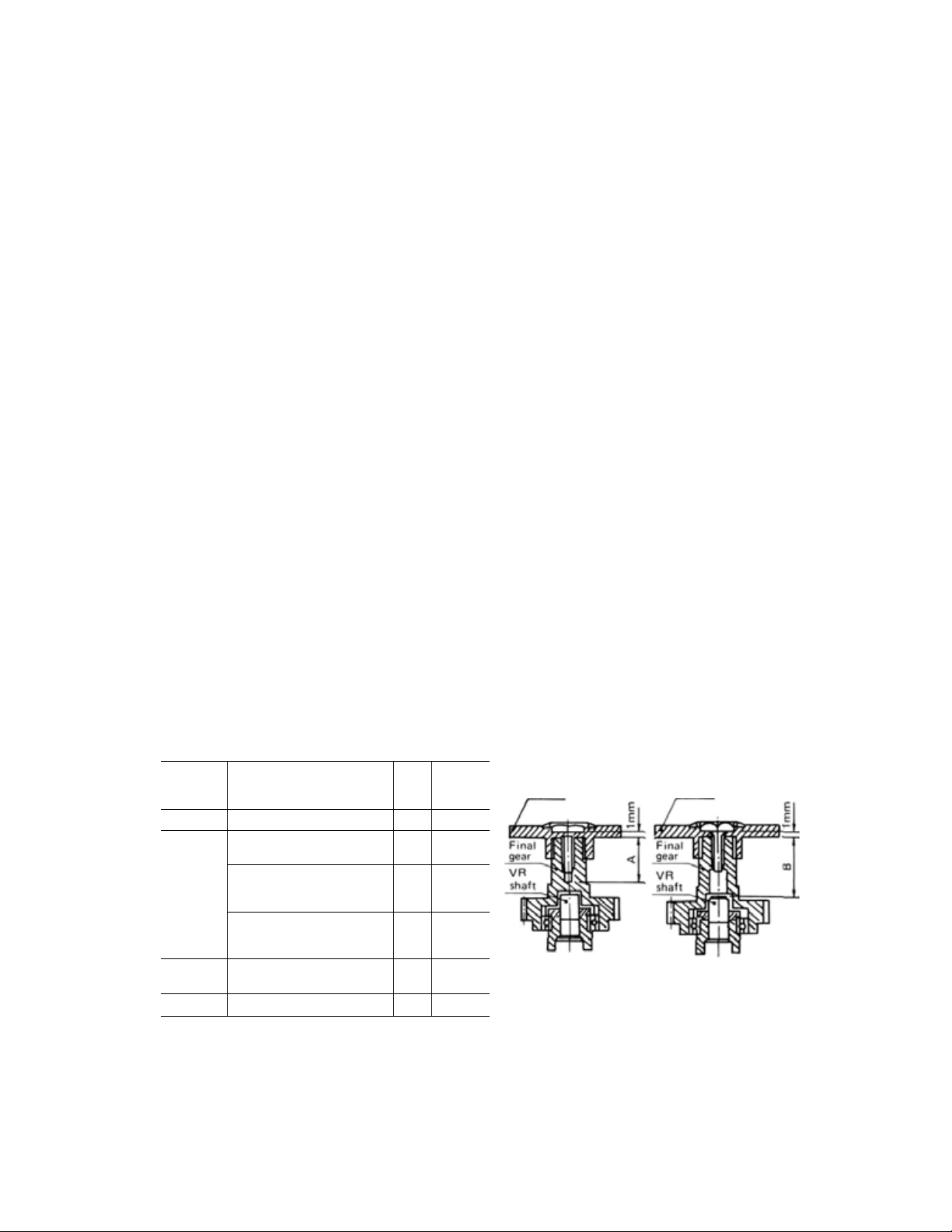
SERVO HORN MOUNTING SCREW PRECAUTIONS
Servo horn screws
Horn
mounting
screw size
2.6x6
2.6x8
2.6x10
2.6x12
Notes
• The screws are 2.6m/m tapping screws.
• If screws longer than necessary are used, the final gear may be broken or the potentiometer may be damaged or
may fall out.
Applicable servo
S133, S143 series
S 129 series
S130 series, S9101, S5101
S128 series
S132 series
S135 series, S9601
S136G
S138 series
S148 series
S131S series, S9201,S9301
89401
8134 series, 83301
Type
B
A
A
B
B
B
A
B
B
A
A
Dimen-
sions
(m/m)
5.7
7.9
7.9
11.9
7.3
8.7
9.0
9.9
10.5
9.0
11.3
Horn
Waterproof type A Non-waterproof type B
Horn
-5-
Page 8
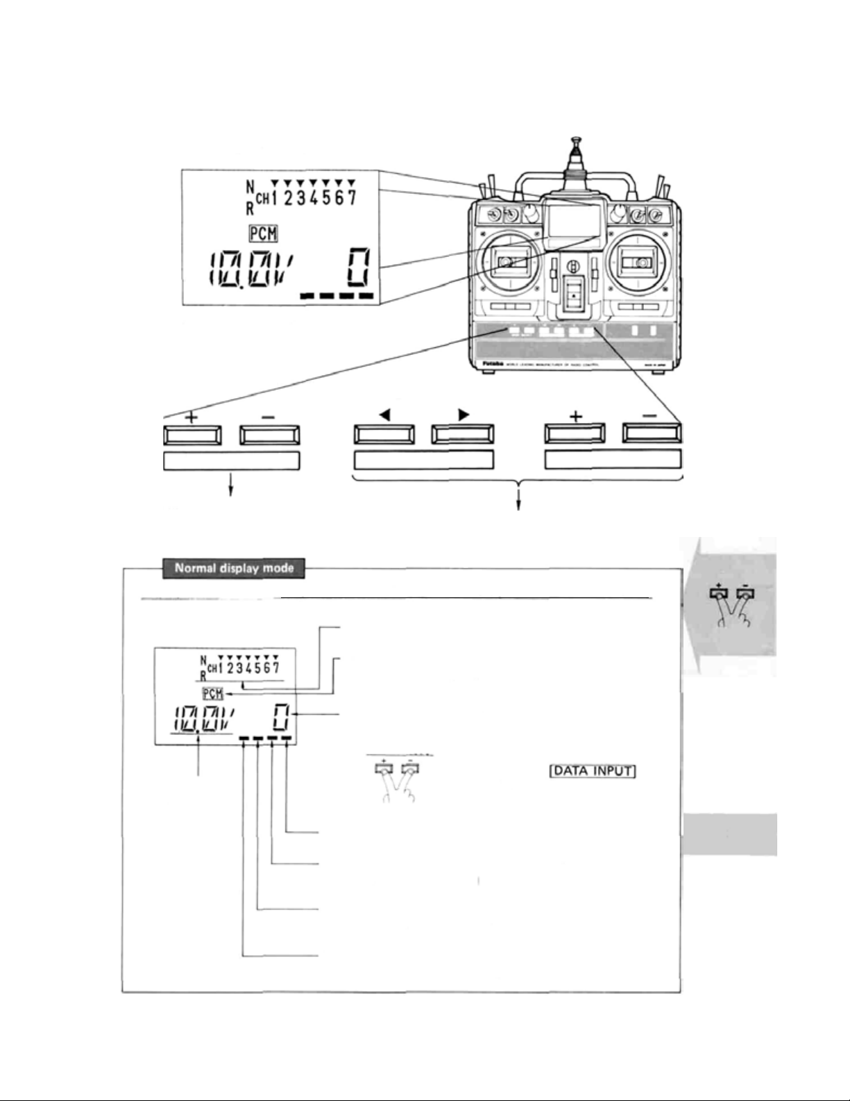
• DISPLAY FUNCTION
Liquid crystal panel
• Operated in three display modes
ED I T KEY
MODE SELECT
• Used in display mode switching.
• Used in setting function selection
Display mode at_normal use (Mode which is displayed when the power switch is turned on.)
(Display)
Battery voltage
display
• Reverse function display
(N: Normal, R: Reverse)
• PCM/PPM mode d isp lay
(PCM: PCM mode, PPM: PPM mode)
• Integrated time display (0—199 minutes)
(Displays the integrated time after reset.)
• Flashes at a 1 second period
CURSOR
• Used at data setting.
Clock reset
Reset by pressing the
simultaneously.
DATA INPUT
Display
keys
Error
• F/S data transfer display (FP-7UAP only)
(Lights momentarily each minute)
• RF indicator
(Lights when radiowaves are transmitted.)
• Mixing indicator
(Flashes when
snap roll mixing or 6 -> 2 mixing is ON.)
—6—
Page 9

Function data setting display mode
(Display)
• DISPLAY FUNCTION
ATV
P.8
MOD
P.19
mode switching
The display mode is
switched by pressinq the
keys simul-
taneously.
Function name
Function setting parameters
(See the individual function
setting items.)
(Set function recall)
• The function is selected by
I MODE SELECT | key.
D/R
EXP
REV
F/S
PMX1
PMX2
2->6
+ direction
P.8
P.9
P.9
P.10
P.11
P.12
P.13
COMB
STRM
FLTR
FLPR
DIFF
SNP
6->2
P.18
P.18
P.18
P.17
P.16
P.15
P.14
Error
generation
Display mode at error generation (Switched automatically from other modes)
(LOW BATTER Y error display)
• The characters flash and a buzzer sounds.
Charge, or change, the battery.
Charqinq method P4
(BACK-UP error display)
• Characters flash and a buzzer sounds.
Turn off the power switch and then turn on.
-7-
Page 10

• FUNCTION AN D DATA SETTING
Function
ATV
ADJUSTABLE TRAVEL
VOLUME
This function adjusts the servo left
and right throws and is used in
linkage correction.
• The rate can be set for each channel.
• The left and right (up, down) rate
can
be
set.
• The rate setting range is 30% to
110%.
Display
R/U: Right or up
L/D: Left or down
Press th e [MODE
CH selection
Direction selection
Rate setting
Set for a different CH and direction by re-
peating steps
SELECT]
Data setting
Select the CH to which ATV is
to be applied with the
keys.
Select the Direction with the
The rat e described below is set
Set the rate with the
— keys are pressed simultaneously,
100%
To normal display mod*
, or
keys. (When the + and
is
set.)
The rate can be switched with the
• D/R can be set for CH1 (aileron),
CH2 (elevator), and CH4 (rudder).
• D/R can be set fo r each direction
of
the
With this feature you can select
which switch position you want
for high rate and low rate.
• The rate setting range is 30% to
110%.
•Related function COMBINATION
SWITCH.
To D /R
D/R switch direction selection
Set for a different CH and
direction by repeating steps
Select the CH f or which D/R is
to be set with the
keys.
Switch to the direction for
which the
be
set.
Set the rate with the
— key s are pressed simultaneously.
keys. (When the + and
100%
is
set.)
to
is
to
8
Page 11

• FUNCTION AN D DATA SETTING
Function
EXP
EXPONENTIAL
This function modifies the operating curve so that operation is easy
when the movement of the servos
becomes sluggish or sensitive near
the neutral position.
•EXP can be set for CH1 (aileron),
CH2 (elevator), CH3 (throttle),
and CH4 (r ud de r) .
• The rat e can be set for each direction of the
(However, there is no
•The
(slow side) to +100% (quick side)
in 4% steps.
for the throttle.)
rate setting range
is
—100%
Display
Press the [MODE SEL ECT]
Data setting
CH selection
Select the CH to which EXP is
to be applied with the
keys.
D/R switch direction selection
Switch to the direction to which
the
Rate setting
Set the rate with the
- keys are pressed simultaneously,
0%
is
Set for a different CH and
direction by repeating steps
(Note) At initial flight, test at EXP 0%. Adju stm ent as desired in accordance with flight
is recommended.
To normal display mode
is
to
be set.
keys. (When th e + and
set.)
Function
REV
REVERSE
Used when modifying servo direc-
tion of operation.
• Can be set fo r each channel.
Display
N: Normal side
R: Reverse side
To
REV
Data setting
CH selection
Select the CH for which REV is
to be set with the
keys. (CH NO. flashes)
Direction of operation setting
Set the direction with the
+ : Normal
—: Reverse
Set for another channel by repeating steps
and
(Note) Be especially careful in the aileron
direction.
keys.
-9-
To F/S
Page 12

• FUNCTION AND DATA SETTING
F/S
FAIL SAFE
F/S and HOLD functions
• F/S and
• The F/S and HOLD functions can
(HOLD function setting)
When interference makes reception
impossible, the servos are stopped
in position just before erroneous
operation is performed.
When the interference ceases, the
HOLD mode is released.
(F/S function setting)
When interference makes reception
impossible, the servos move to the
position set at t h e transmitter.
When the interference ceases, the
F/S function is reset.
HOLD can be set for all
channels.
be selected f or each channel.
Press
the
CH selection
[MODE
SELECT]
Select the CH which is to be
set to F/S or HOLD with the
To normal display mode
keys. (CH NO.
flashes)
Function selection
Select the function with the
+ : HOLD function
—: F/S function
Select the function for another channel by
repeating steps
F/S function selected CH servo operating
position setting
and
Set the flashing display to
"SET" with the
keys.
The channel
or
F/S function was selected is
held in the desired position.
Press the
simultaneously. (The servo operating position is set. At the same
time, data is automatically sent
to the receiver.)
keys.
for which the
keys
*The F/S set data is automatically
sent every minute.
*The PPM mode does not have an
F/S function. (FP-7UAF)
*When using the B.F/S function,
set the throttle channel F/S function.
-10-
To
PMX1
Page 13

• FUNCTION AN D DATA SETTING
PMX1
PROGRAMMABLE MIXING 1
This mixing is useful in correcting
bad tendencies of the aircraft and
in making operation more pleasant.
• Mixing of any two channels is
possible.
• The left and right (up and down)
mixing rate can be set independently.
• Setting range: 0 — 100% (mixing
maximum)
(INH: Inhibit state)
Activate state
ON:
OFF:
ON
OFF
Press the [MODE SE LECT ]
Mixing activate/inhibit mode setting
Set the mode with the
+ : Activate
—:
Inhibit
Master channel selection
Set the flashing display to the
mark with the
keys.
Select the channel to be set wit h
the
Slave channel selection
Set the flashing display to the
mark with the
keys.
Select the channel to be set wi th
the
To normal display mod e
keys.
keys.
keys.
R/U: Right or up
L/D: Left or down
Mixing servo direction of operation setting
Set the flashing display to "+"
(or "—") with the
keys.
Held as long as the master channel stick (VR or switch) is in the
R/U or L/D direction.
Set the direction of operation
with the
+ : Normal direction
—: Reverse direction
Set another direction by repeating steps
Mixing rate setting
Set the flashing display to "%"
with
Set the same as
Set the mixing rate with the
(When the + and — keys are
pressed simultaneously, 50% is
set.)
Set the same as
and
keys.
keys.
keys.
To PMX2
—
11
—
Page 14

• FUNCTION AND DATA SETTING
PMX2
PROGRAMMABLE MIXING 2
This mixing is useful in correcting
bad tendencies of the aircraft and
in making operation more pleasant.
• Mixing of any two channels is
possible.
• The left and right (up and down)
mixing rate can be set independently.
Press the [MODE SELECT]
Mixing activate/inhibit mode setting
Set the mode wi th the
+ : Activate
-: Inhibit
Master channel selection
Set the flashing display to the
mark with the
keys.
Select the channel t o be set with
the
Slave channel selection
Set the flashing display to the
mark with the
keys.
Select the channel to be set with
the
To normal display mode
keys.
keys.
keys.
R/U: Right or up
L/D: Left or down
Mixing servo direction of operation setting
Set the flashing display to "+'
(or "—")
keys.
Held as long as the master channel stick (VR or switch) is in the
R/U or L/D direction.
Set the direction of operation
with the
+ : Normal direction
-:
Set another direction by repeating steps
Mixing rate setting
Set the flashing display to "%"
with
Set the same as
Set the mixing rate with the
(When the + and — keys are
pressed simultaneously, 50% is
set.)
Set the same as
with the
keys.
Reverse direction
and
keys.
keys.
—12—
To
2-6
Page 15

• FUNCTION AND DATA SETTING
2-6
ELEVATOR ->> FLAP MIXING
This is used to apply mixing from
elevator to flap. Mixing is usually
used so that the flaps are lowered
when the elevator is raised. It
makes circular maneuvers with
stunt aircraft smoother.
• The elevator up side and down
side mixing rate can be set independently.
(INH: Inhibit state)
Pressthe [MODE SELECT]
Mixing activate/inhibit mode setting
Set the mode with the
+ : Activate
-: Inhibit
Mixing servo direction of operation setting
Set the flashing display to "+"
(or "—") with the
keys.
Held as long as the elevator
direction.
Set the direction of operation
with t h e
+ : Normal direction
—: Reverse direction
Set for another direction of the
elevator
steps
To normal display mode
keys.
is
in the R/U or
and
keys.
by repeating
L/D
ON side
OF F side
R/U: Right or up
L/D: Left or down
Mixing rate setting
Set the flashing display to "%"
with the
Held as long as the elevator
direction.
Set the mixing rate with the
(When the + and — keys are
pressed simultaneously, 50% is
set.)
Set a different elevator
direction by repeating steps
and
keys.
is
in the R/U or
keys.
L/D
To
6->2
13
-
Page 16
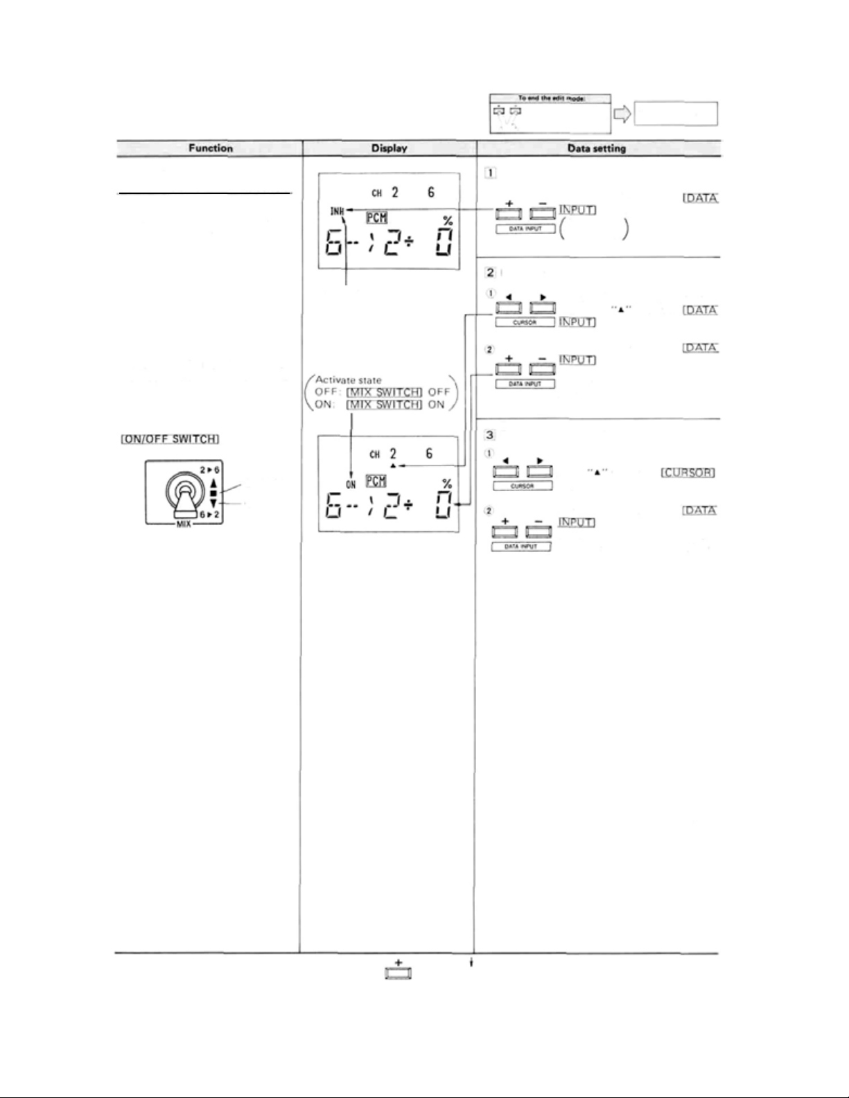
• FUNCTION AN D D AT A SETTING
6-2
FLAP -> ELEVATOR MIXING
Use this mixing when an air brake
is necessary when landing or diving,
etc. during flight.
• The operating position of the
elevator and flap servos can be
set.
OFF side
ON side
(INH: Inhibit state)
Press the [MODE SELECT]
Activate/inhibit mode setting
Set the mode with the
Elevator servo throw setting
Set the flashing display to the
channel 2
Set the rate with the
(When the + and — keys
pressed simultaneously, 0%
set.)
Flap servo throw setting
Set the flashing display to channel
keys.
Set the throw
(When the + and — keys are
pressed simultaneously, 0% is
set.)
keys.
+ : Activate
-: Inhibit
keys.
keys.
6
keys.
with the
To normal display mode
with the
are
is
with the
-14
ToSNP
-
Page 17

• FUNCTION AN D DATA SETTING
SNP
SNAP-ROLL
Avalanche and other snap rolls can
be performed by switch.
• Four snap roll directions can be
set.
R/U: Right up snap
R/D: Right down snap
L/U: Left up snap
L/D: Left down snap
• The throw of the channel 1 (aileron), channel 2 (elevator), and
channel 4 (rudder) servos can be
set.
• The SAFETY mode can be set.
(Mode in which operation is not
performed when the landing gear
is down even if the switch is turn-
ed on by mistake.)
(I NH: Inhibit state)
"1" to "4" is displayed
according to the
position.
1:
R/U
R/D
2:
3:
L/U
4:
L/D
Press
the [MODE SELECT]
Activate/inhibit mode setting
Set the mode with the
keys.
+ : Activate
-: Inhibit
Select the direction
RIGHT
UP
Switch
the
to the combination
DOWN
of directions to be set.
LEFT
Aileron servo throw setting
Set the flashing display
with the
Set the rate with the
keys.
(When the + and — keys are
pressed simultaneously, 100% is
set.)
Elevator servo throw setting
Set the same as
Rudder servo throw setting
Set the same as
Set for each direction of the
by repeating steps
To normal display mode
to CH1
keys.
to
SNAP ROLL
UP
DOWN
RIGHT
LEFT
F: SAFETY mode released
5L: SAFETY mode set and
ON
5F: SAFETY mode set and
OFF
-
15
—
ToDIFF
SAFETY mode setting
Set
the
Set
the
direction for which snap roll is
to be turned off (direction in
which landing gear is down).
Press the — side of the
SAFETY mode release
Set
the
Press the + side of the
to CH5 with
keys.
keys.
to CH5 with the
keys.
keys.
the
to
the
Page 18

• FUNCTION AND DATA SETTING
DIFF
AILERON DIFFERENTIAL
A left and right differential can be
applied to the ailerons. This is effective in roll axis correction. (Left
and right aileron servos are necessary.)
• The operating channels are CH1
and CH7.
•AIL
DIFF
AND
not be on simultaneously. The
FLAPERON
function turned on last has priority.
can-
(INH: Inhibit state)
(ON: Activate state)
Pressthe (MODE SELECT]
keys simultaneously
Activate/inhibit mode setting
Set the mode with the
+ : Activate
-: Inhibit
Set the CH1 servo direction of operation.
Set the flashing display to "+"
or "—" with the
keys.
Held as long as the aileron
(Channel 1 side selected.)
Set the direction of operation
with the
+ : Normal direction
—: Reverse direction
CH7 servo direction of operation setting
Held as long
To normal display mode
keys.
is at the right.
as the aileron
is at the left.
keys.
Set the direction of operation
with the
+ : Normal direction
—: Reverse direction
CH1 servo throw setting
Set the flashing display to "%"
with the
Held as lonq as the aileron
Set the rate with the
keys.
(When the + and — keys are
pressed simultaneously, 100% is
set.)
CH7 servo throw setting
Held as long as the aileron
is at the left.
Set the rate with the
keys.
(When the + and — keys
pressed simultaneously, 100% is
set.)
keys.
keys.
is at the riqht.
are
—
16
To FLPR
-
Page 19

• FUNCTION AND DATA SETTING
FLPR
FLAPERON
This is a mixing function which
gives the ailerons a flap function.
The ailerons can be raised and
lowered simultaneously. Aileron
operation is also performed.
• The operating channels are CH1
and CH6.
Ailerons can be raised and lowered simultaneously.
*AIL DIFF and FLAPERON can-
not be on simultaneously. The
function set last has priority.
(INH: Inhibit state)
(ON: Activate state)
Press
the
[MODE
SELECT]
Activate/inhibit mode setting
Set the mode with the
+ : Activate
-: Inhibit
Set the CH1 servo direction of operation
Set the flashing display to "+"
or "—" with the
keys.
Held as lonq as the aileron
(Channel 1 side selected.)
Set the direction of operation
with the
+ : Normal direction
—: Reverse direction
CH6 servo direction of operation setting
Held as long as the aileron
Set the direction of operation
with the
+ : Normal direction
—: Reverse direction
To normal display mode
keys.
is at the right.
is at the left.
keys.
keys.
To FLTR
CH1 servo throw setting
Set the flashing display to "%"
with the
Held as long as the aileron
Set the rate with the
keys.
(When the + and — keys
pressed simultaneously, 100% is
set.)
CH6 servo throw setting
Held as long as the aileron
Set the rate with the
keys.
(When the + and — keys are
pressed simultaneously, 100% is
set.)
keys.
is at the right.
are
is at the left.
—
17—
Page 20

• FUNCTION AND DATA SETTING
FLTR
FLAP TRIM
FLAP TRIM (CH6) lever operation
<-> normal operation switching is
possible.
*For operation when FLAPERON
is used, see the FLAPERON function item.
STRM
SUB TRIM
The stick channel (CH1 — 4) trim
lever operating position can be
adjusted.
*0ne
notch
of the
trim
lever
responds to a sub trim of about
6%.
cor-
(INH: Normal operation)
(ON: Trim operation)
To STRM
Press the. [MODE SE LECT]
Trim/normal mode setting
Set the mode with the
keys.
+ : Trim mode
—: Normal mode
Trim rate setting
Set the flashing display to "%'
with the
Set the rate with the
keys.
(When the + and — keys are
pressed simultaneously, 30% is
set.)
CH selection
Select the channel with the
Operating position setting
Set the operating position with
the
(When the + and - keys are
pressed simultaneously, 0% is
set.)
To normal display mod e
keys.
keys.
keys.
COMB
COMBINATION SWITCH
Other D/R switch functions can be
combined by aileron D/R switch.
• Three modes can be set.
Mode
1
2
3
D/R switch to be
combined
AIL only
AIL.
ELV
AIL,
ELV, RUD
Displays the channel
No. of the D/R switch
to be combined.
Displays the mode
No.
1: Mode 1
2: Mode 2
3: Mode 3
—
18
To COMB
Mode setting
Set the mode with the
keys.
To MOD
-
Page 21

• FUNCTION AN D D ATA SETTING
• OTHER FUNCTIONS
MOD
MODULATION
The modulation can be switched
PCM
<->
PPM
mode.
* Select the PCM mode for the FP-
7UAP and the PPM mode for the
FP.7UAF.
*When using the trainer function.
select the same mode at the instructor side and student side
transmitters.
• Stick lever tension adjustment
1 Remove the transmitter back cover.
When the mode is changed, the
display flashes.
The actual transmit output at
that time is the mode before the
change.
Press the [MODE SELECT]
Mode selection
Select the mode with
To normal display mode
keys.
*When the mode was switched, the transmit-
ter power sw itch is turned off and transmit
C:PCM
F:PPM
output is obtained the next time the transmitter power switch is turned on.
ToATV
• Non-slip adjustable lever head adjustment
The length of the lever head can be changed.
the
2 Adjust the spring strength.
Set to the desired spring
Elevator
Aileron
Strength by turning the
screw of each stick.
Remove the four
screws and remove
the back cover.
Rudder
Use a small Phillips
screwdriver.
Lever head
Unlock lever heads
opposite directions as shown by the arrows and
adjust the sti ck to the most co m f or table length.
• Receiver B.F/S function
Lever head
and
by turning them in
When the receiver battery voltage drops below a
certain value, the throttle servo moves to a preset
position. (B.F/S mode)
At this time, reset the B.F/S mode and immediately land the aircraft.
1 B.F/S mode position setting
• Set the throttle channel (CH3) to the F/S
function.
Settinq method
•The
set
position should
be
close
to
maxi-
mum slow.
2 B.F/S mode resetting method
Throttle stick
•When the throttle stick
is set to the maximun
slow position, the B.F/S
mode is reset.
—
19—
Page 22
• OTHER FUNCTIONS
• USING THE ACCESSORIES
• Trainer function (Trainer cable optional)
1 Connection to transmitter
Trainer switch
Student transmitter
Instructor transmitter
Trainer cable (6-conductor)
*Operation is impossible if the instructor transmitter modulation
mode and student transmitter modulation mode is different.
to the same mode before using. Setting method
Always turn off the student transmitter power switch. Do not
operate the trainer switch either.
*Use the functions of the other two transmitters with the same
setting.
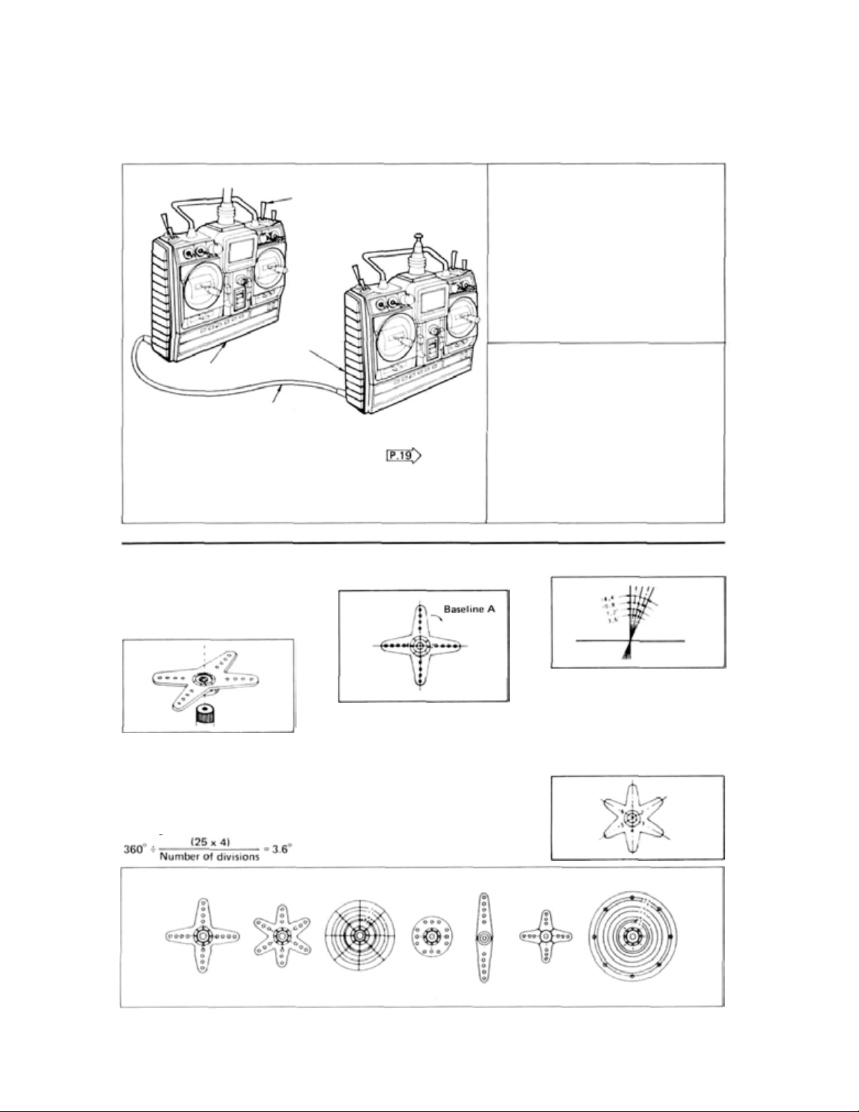
• SPLINED HORNS
This horn permits shifting of the
servo neutral position at the servo
horn. Setting and shifting the
neutral position.
a) Angle divisions
b) Effect
2 Operating at the instructor side
Operation is possible by turning on the
instructor transmitter power switch. At
this time, turn off the trainer switch.
3 Operating at the student side
Operation is possible at the student
transmitter while the trainer switch at
the instructor side is held in the ON
state.
Set
To shift the holes center line to
the right (clockwise) relative to
1) The splined horn has 25 segments. The amount of change per
segment is; 360/25=14.4°.
2) The minimum adjustable angle
is determined by the number of
arms or number of the holes. For
four arms, the minimum adjust-
able angle is:
baseline A, shift arm 2 to the position of arm 1 and set it to the
position closest to baseline A.
[Example] For a four arm horn,
the angular shift per segment is
14.4°. The s hi ft t o the right is 90°
-
(14.4 x 6) = 3.6°.
To shift by the same angle in the
opposite direction, use the opposite arm number.
The following splined horns are optional.
HORN A
(FSH6X)
HORN B
(FSH
6)
HORN C
(FSH
6A)
—
HORN D
(FSH
20—
6W)
HORN E
For a six arm horn, turn the arm
counterclockwise and set arm 2
to the position of arm 1. The ad-
justable angle is 60° - (14.4 x 4)
=2.4°.
Arm 3 shift 4.8° to the right, arm
6 shifts 2.4° to the left, and a rm 4
shifts 7.2° to the right and left.
HORN F
HORN G
Page 23

• USING THE ACCESSORIES
• Digital Proportional Frequencies (FOR U.S.A.)
•
The
frequency
you to choose from (27 MHz and 75 MHz.) Please see chart listed below for specific frequency and its intended use.
Please note there are specific frequencies allocated for aircraft only and surface only use.
•The
frequency can be changed
Futaba recommends that you return your system to our factory service department for frequency changing, as tuning
may be necessary for proper operation. Changing frequency from one band to another is NOT possible.
• Always change frequency flag when frequency is changed. The frequency flag is to be attached to the top of antenna
and th e channel designation to the base. (See Drawing)
•
It
is illegal to change crystals on 75 MHz bands in the
• ANTENNA FREQUENCY FLAG
of
Futaba
digital
proportional
within
the
sets can be
same
BAND
changed
by
U.S.A.
within
using a precisely
their
matched
own
band.
pair
There
are 2 different
of
Futaba crystals.
bands
for
However,
The flag can be attached
to, and removed from, the
antenna with one touch.
Attach the frequency flag to the flag holder
as shown in the figure.
• Frequency Channel No. Flag Color (FOR U.S.A.)
—21
—
Page 24

Liquid crystal panel
Antenna
Carrying
• NOMENCLATURE
bar
Neck strap hook
Aileron trim lever
RF module
Rudder trim
lever
Elevator
Throttle trim lever..... (MODE I)
Power switch
Throttle trim lever..... (MODE II)
Elevator trim lever..... (MODE I)
trim
lever.....
(MODE
II)
Charging jack
(w/dust cap)
Trainer jack
(w/dustcap)
Battery cover
—
22
—
Page 25

• SERVO EXPLODED VIEW
FP-S148 FP-S3001
No.
1
Upper cas e
2
Middle case
Bottom case
3
4
Metal bearin g inner
Metal bearing outer
5
TR133 15
6
7
VR drive plate
Motor
8
Motor pinion
9
10
Motor mounting screw
11
1st gear
2nd gear
12
3rd gear
13
14
Final gear
Intermediate shaft
15
2nd shaft
16
Splined horn 0
17
Horn mounting screw
18
AMP
19
S148 3P8SWRB300C
20
Grommet
21
Case mounting screw
22
Nameplale
23
Part Name
Part No.
S06015
S06005
S06006
S04137
S04136
139668
S02753
S91239
S02461
J50002
S02490
S02491
S03266
S02752
S02495
S02494
SO
1239
J55178
AS1157
AT2453
S90045
S50360
S60099
—23—
No.
Upper case
1
Middle case
2
Bottom case
3
4
Metal bearing inner
Metal bearing outer
5
TR133 15
6
VR drive plate
7
Motor
8
Motor pinion
9
Motor mounting screw
10
11
1st gear
2nd gear
12
3rd gear
13
14
Final gear
Intermediate shaft
15
2nd shaft
16
17
Bearing L 1060
Splined horn D
18
Horn mounting screw
19
AMP
20
3PB-SWRB300C
21
Grommet
22
Case mounting screw
23
24
Nameplate
Part Name
Part No.
S06100
S06005
S06006
S04137
S04136
139668
S02753
S91239
S02461
J50002
S02490
S02491
S03266
S02752
S02495
S02494
S04130
SO
1239
J55178
AS1341
AT2453
S90045
S50085
S60189
Page 26

Printed in Japan/900330CC
 Loading...