

Page 1
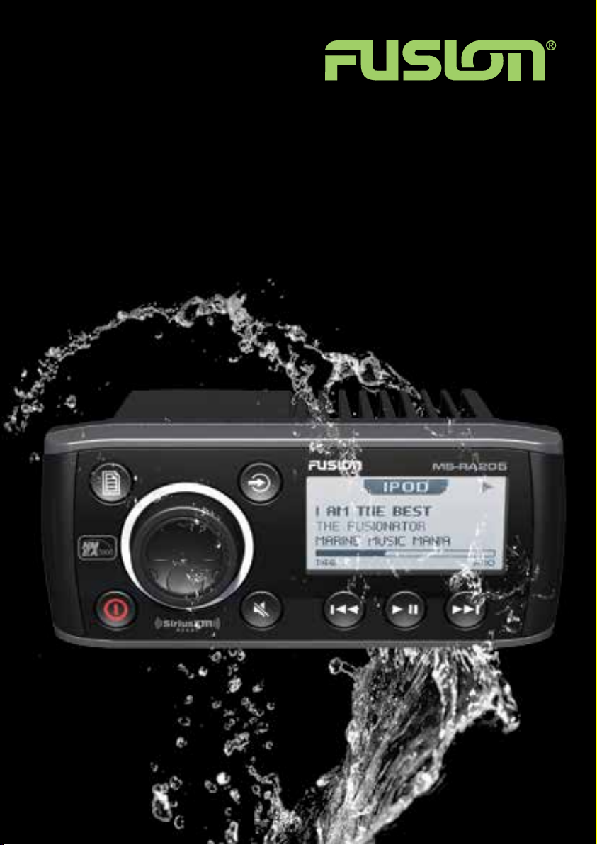
USER / INSTALLATION MANUAL
MS-RA205
TRUE MARINE STER EO
Page 2

PRECAUTIONS
Do not attempt to open the unit. There are no user serviceable parts or
adjustment’s inside.
No responsibility can be taken for use of the unit other than under normally expected
operating conditions.
If exposed to direct sunlight or operated for extended periods metal surfaces may
become hot. Take care when handling.
USI NG iPod/iPhones
This unit has been tested with compatible authentic iPod models under normal expected operating
conditions, free from any pre-existing defects in either the unit or the iPod.
No responsibility can be taken for use of the unit other than under normally expected operating
conditions in conjunction with fully functional and undamaged iPod units which have been
manufactured and authorized by Apple Inc.
USB FLASH DRIVES
• Drive format: All USB flash drives used with this unit must be formatted to either FAT32
or NTFS format. These are the most commonly used format for USB flash drives.
• Audio track format: Audio tracks stored on USB flash drive must be in MP3, M4A or FLAC formats
to play on this unit.
CARE AN D MAI NTENANCE
As with all products exposed to the harsh marine environment, a little care will help preserve the
finish. FUSION recommends that you clean any salt water and/ or salt residue from the stereo with
a damp cloth soaked in fresh water.
Most marine Stereo’s have small vents in their cases to allow a way out for moisture that finds its
way in. In some limited instances it is possible for moist air to be drawn into the vents when the
air inside the Stereo cools down after it is turned off. Direct sunlight on the front can draw this
moisture up against the Window, causing fogging. Turning on the Stereo will speed up moisture
removal. Fogging is not abnormal, nor will it harm your Stereo, which is built to withstand the harsh
marine environment.
REGISTER YOU R PRODUCT ONLINE
For your own peace of mind, register your product purchase online at
www.fusionelectronics.com
We’ll keep you up to date with any news related to your product or new
accessories to help you get the most from your product.
RECORD YOUR PRODUCT D ETAILS HERE:
SERIAL NUMBER DATE OF PURCHASE
AFFIX RECEIPT HERE
2
Page 3

CONTENTS
INSTALLATION ........................................................................................................ 4
WIRING DIAGRAM ...................................................................................................7
CONNECTIONS ........................................................................................................ 8
BUTTON DESCRIPTION ......................................................................................... 10
GENERAL OPERATION .......................................................................................... 12
RADIO OPERATION ................................................................................................ 16
USB OPERATION ................................................................................................... 17
AUX OPERATION ................................................................................................... 17
iPod/iPhone OPERATION ....................................................................................... 18
ANDROID (MTP) DEVICE OPERATION
19
BLUETOOTH OPERATION ...................................................................................... 20
SiriusXM SATELLITE RADIO .....................................................................22
ZONE OPERATION ................................................................................................. 23
ADDITIONAL FEATURES ........................................................................................ 24
MENU STRUCTURE ............................................................................................... 25
TROUBLESHOOTING ............................................................................................. 26
FUSION MARINE ACCESSORIES ............................................................................ 28
SPECIFICATIONS AND LICENSING ........................................................................ 30
3
Page 4
INSTALLATION
If any modification to the vessel is required, such as drilling holes etc FUSION
recommends consultation with your boat dealer or manufacturer beforehand.
Create mounting hole for product and drill Screw Pilot Holes.
Refer to mounting template included with product or download
from www.fusionelectronics.com
• Fit mounting gasket
• Insert the unit into the mounting hole
• Use the supplied 4 x self tapping screws, to affix the unit into position.
• Attach screw covers
Note: Appropriate mounting is very important to ensure correct operation. Select a location
that allows both free/open air flow around rear of chassis, whilst minimizing exposure to
moisture. Allow adequate room at the rear of the unit for the cable looms (approx 2”) and
underneath the unit (approx 2”) if using a SiriusXM tuner (USA Only).
Note: The head unit must not be mounted on more than a 45˚ angle
45˚
from the horizontal plain. Failure to follow mounting restrictions
could void your warranty.
4
Page 5

Mounting Gasket
Screw Covers
Mounting Hole
Screw Pilot Hole
5
Page 6
ELECTRICAL WI R I NG
Caution: The MS-RA205 is designed for vessels with a 12V DC Negative ground electrical system
Rear support holes
SiriusXM REMOTEAERIAL
USB
In some cases a rear support strap (not supplied) may be required. Please use the two holes
indicated above, to attach the strap using two 8 gauge x 8mm self-tapping screws (not supplied).
INSTALL ATION WARNING
• Ensure the marine vessels +12V lead is removed from the battery
before any equipment is connected
• Investigate the marine vessels fuel tanks and electrical wiring
locations before you begin installation
• Ensure all wiring is protected to avoid damage
When wiring the MS-RA205, ensure that the wires are away from sharp objects and
that rubber grommets and insulated bungs are used when routing the wiring. Ensure
that when connecting the wires to the speakers and audio system, the terminals and
connections are protected from shorting to each other.
Note: Ensure the antenna cable is routed away from any power cables, and is the minimal
length, as long cable runs will affect AM reception performance.
For optimum radio reception please ensure you use a dedicated AM/FM ground
independent marine antenna.
The use of a VHF splitter is not recommended as this will degrade your marine VHF
radio performance.
Please refer to the following site for further info: www.pacificaerials.co.nz
Note: The head unit is IPx5 rated on the face when correctly bulkhead mounted. Failure to
mount the head unit correctly may void your warranty.
6
Page 7
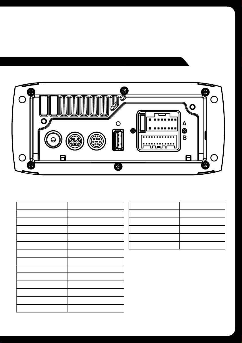
ELECTRICAL ISOLATION OF THE MS-RA205
The MS-RA205 stereo has a metal chassis which is connected to the Ground /
Negative / Black wire (like most other stereos).Extra care should be taken when
installing this type of stereo in an aluminium boat (or boats with a conductive hull) if
you require the electrical system to be isolated from the boat hull).
WIRI NG DIAGRAM
SiriusXM REMOTEAERIAL
USB
A CABLE B CABLE
YELLOW BATTERY (+12 V constant)
RED IGNITION (+12V switched)
BLACK GROUND (-12v)
WHITE SPEAKER ZONE 1 L (+)
WHITE/BLACK STRIPE SPEAKER ZONE 1 L (-)
GREY SPEAKER ZONE 1 R (+)
GREY/BLACK STRIPE SPEAKER ZONE 1 R (-)
GREEN SPEAKER ZONE 2 L (+)
GREEN/BLACK STRIPE SPEAKER ZONE 2 L (-)
PURPLE SPEAKER ZONE 2 R (+)
PURPLE/BLACK STRIPE SPEAKER ZONE 2 R (-)
BROWN DIM (+12V switched)
BLUE/WHITE STRIPE AMPLIFIER ON
BROWN/WHITE STRIPE TEL MUTE/INTERRUPT AUX
WHITE RCA (Grey wire) AUX-IN (L)
RED RCA (Grey wire) AUX-IN (R)
ORANGE RCA (Black wire) SUB-OUT
ORANGE RCA (Black wire) SUB-OUT
WHITE RCA (Black wire) LINE-OUT ZONE 1 ( L)
RED RCA (Black wire) LINE-OUT ZONE 1 (R)
Note: Minimum speaker load impedance 4 Ohm
7
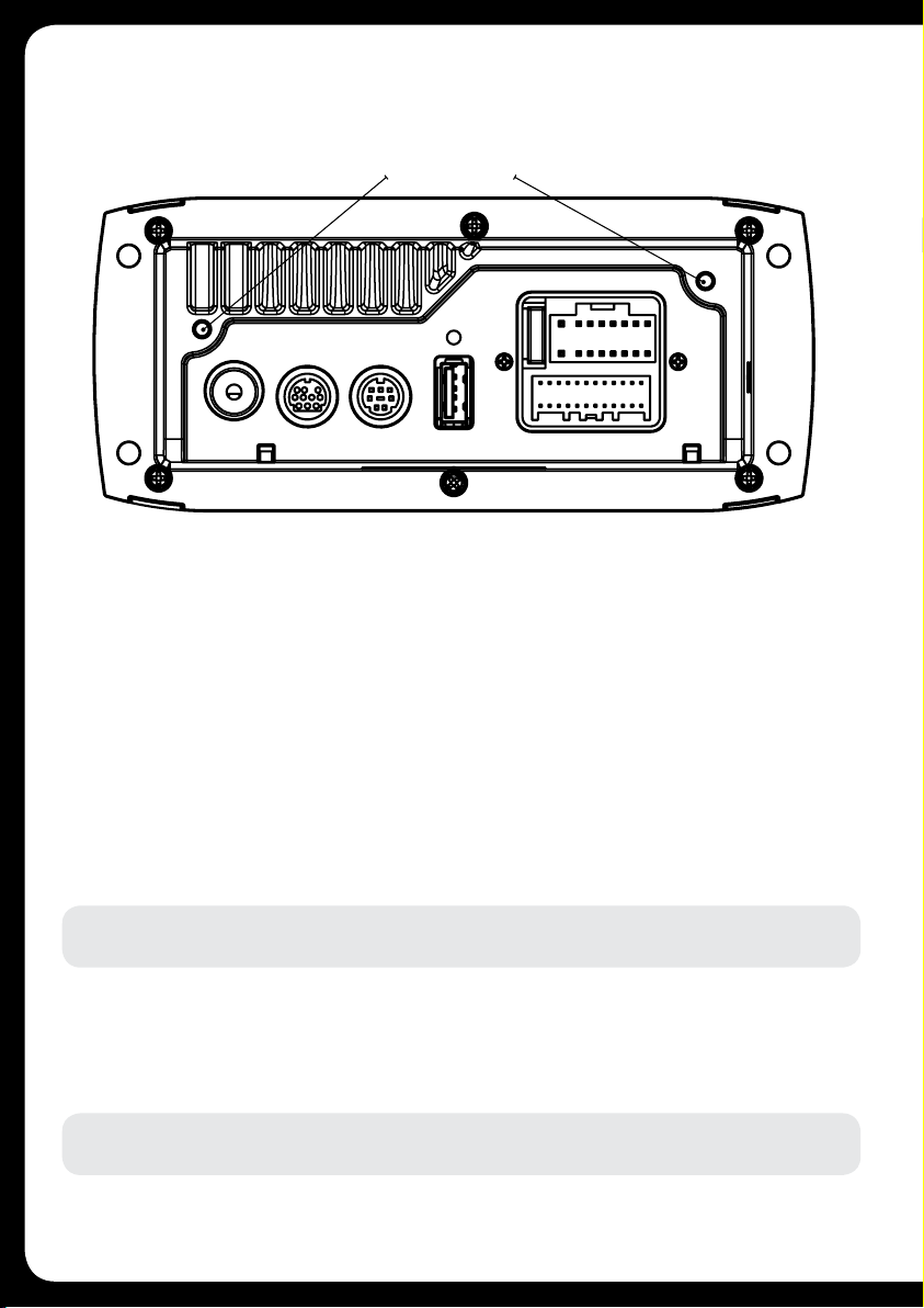
Page 8
CON NECTIONS
CON NECTOR A
BATTERY +12VDC
Connect to the battery positive (+12VDC), or bus bars. A fuse or circuit breaker MUST
be used at the battery end of the cable. Use a minimum wire size of 16AWG for wire
length up to up to 6 meters / 20 feet.
IGNITION +12V switched
Connect to a separate switched +12V wire to control stereo ON/Off operation.
Alternatively connect to the battery positive (+12VDC), or bus bars.
When the red “Accessory +12V switched” wire is not required for ignition on/off
control, it MUST be connected together with the Yellow “Battery +12V” wire at the
MS-RA205 head unit wiring loom.
GROUND WIRE — Recommended minimum wire size for Negative Ground wire:
16AWG for wire length up to up to 6 meters / 20 feet.
DIM — Connect to vessel lighting sytem to dim LCD and button illumination when
vessel lights are turned on. When connecting the DIM input ensure the wire gauge
used is suitable for the fuse supplying the circuit being connected to.
AMPLIFIER ON — When using an external amplifier connect to the “Remote turn
ON” connection on the external amplifier.
TELE MUTE / INTERRUPT AUX — Connect to handsfree kit to either mute the stereo
or switch to AUX to hear call. When this line is taken to ground the stereo is muted.
SiriusXM REMOTEAERIAL
8
USB
Page 9

CONNECTOR B
AUX INPUT — Connect an Auxiliary source to the left and right RCA
(White = L, Red = R).
SUBWOOFER OUT (DUAL MONO) — Connect to a subwoofer amplifier, volume
control linked to Zone 1. (Orange + Orange)
LINEOUT ZONE 1 — Connect to an amplifier, volume control linked to Zone 1.
(White = L, Red = R).
ANTENNA CONNECTION — Connect an AM/FM marine antenna.
Note: Boat installations do not typically offer the best ground plane environment. For optimum
performance a ground plane independent antenna is recommended.
USB/iPod/MTP CONNECTION — Connect a USB key / flash drive (not included),
a FUSION Marine Uni-Dock (not included), a MTP device or a certified Apple iPod
sync cable (not included).
Media Transfer Protocol (MTP): MTP is a standard developed for connecting media (music)
devices over USB. It has been adopted on a number of platforms including Android. FUSION
currently supports a range of smartphones utilising MTP.
Refer to www.fusionelectronics.com for the latest list of support devices.
SiriusXM SATELLITE RADIO (USA only) — (A) Connect to SiriusXM Connect
Vehicle Tuner (not included) (For use in USA only) (B) Connect the MS-BT200
Bluetooth module (not included).
WIRED REMOTE / NMEA 2000 — Connect the MS-RA205 Stereo to a FUSION
remote control network (cable supplied) or connect to an existing NMEA 2000
network with FUSION optional accessories (not supplied with Stereo):
MS-RA205 NMEA 2000 Drop Cable: CAB000863
FUSION NMEA 2000 T-Connector: CAB000581
Important Note: Adaptor cable CAB000862, provided with the MS-RA205 MUST not be used
to connect the MS-RA205 to an existing NMEA 2000 network. Existing networks are normally
powered separately. The non-powered drop cable (CAB000863) is available from FUSION for
connecting to existing NMEA 2000 networks.
Note: FUSION recommends updating all remote(s) software via the MS-RA205 at time of
installation to ensure compatibility. This can be done via the Update menu. Please refer to your
remote manual for more information.
9
Page 10
BUTTON DESCR IPTION
ROTARY ENCODER
Turn
To adjust volume, move up or down a menu structure,
or adjust a specific setting.
Press
To select a highlighted option, confirm a setting. Press
to step through each zone for volume adjustment.
Press and Hold
For quick access to subwoofer level adjustment
POWER
Press to turn the unit ON/OFF.
Press and Hold
Press and hold for 10 seconds to ‘Reset’ the stereo.
MENU
Press to enter Menu System.
Press to return to previous screen.
Press and Hold
To exit the menu system.
10
Page 11

BACK/PREVIOUS
Short Press
iPod/MTP Device/Bluetooth/USB - Select the previous track.
AM/FM/VHF - Start tuning down the frequency spectrum or
channel. In Auto mode (AM/FM) press to seek down the spectrum
to the next available station. In Preset (AM/FM/VHF) mode step to
previous Preset.
Note: Preset mode is only available if two or more Presets are saved.
SiriusXM (USA Only) - Step down the channel list
Press and Hold
iPod/USB - Rewind the current track.
AM/FM - In MANUAL mode fast station stepping.
SiriusXM (USA Only) - Fast browse down the channel list.
Release button to select channel.
FORWARD/NEXT
Short Press
iPod/MTP Device/Bluetooth/USB - Select the next track.
AM/FM/VHF - Start tuning up the frequency spectrum or channel.
In Auto mode (AM/FM) press to seek up spectrum to the next
available station. In Preset (AM/FM/VHF) mode step to next
Preset.
Note: Preset mode is only available if two or more Presets are saved.
SiriusXM (USA Only) - Step down the channel list
Press and Hold
iPod/USB - Fast forward the current track.
AM/FM - In MANUAL mode fast station stepping.
SiriusXM (USA Only) - Fast browse up the channel list. Release
button to select channel.
SOURCE
Press to cycle through sources
AM - FM - VHF - AUX - iPod - MTP Device - USB - Bluetooth SiriusXM (USA only)
note: Disconnected sources may not be displayed.
PLAY/PAUSE
Short Press
iPod/MTP Device/Bluetooth/USB - Pause / resume the current
track.
AM/FM/VHF - Press to cycle through tuning modes (auto, manual,
presets).
SiriusXM (USA Only) – Press to cycle through tuning modes
(channels, presets)
Note: Preset mode is only available if two or more Presets are saved.
Press and Hold
AM/FM/SiriusXM/VHF – Store the current station/channel as a
Preset
MUTE
Mutes sound in all zones.
11
Page 12

GEN ERAL OPERATION
INITIAL SETUP
Important: The Tuner Region must be selected for correct operation. Default - USA.
See section: Tuner Region Selection
ADJUSTING TH E VOLUM E
Turn the ‘Rotary Encoder’ to adjust the volume.
ZON E VOLUM E
Press the ‘Rotary Encoder’ to step through zones.
All zones Zone 1 Zone 2
SET T I N GS
Press the ’Menu’ button and select ‘Settings’. Select the desired setting to adjust.
Note: Whilst in Settings the ‘Menu’ button acts as a back /return to the previous screen.
Any key press exits the menu screen.
TONE — Adjust the Bass/Middle/Treble settings. Press the ‘Rotary Encoder’ to
cycle between Bass/Middle/Treble
ZONE SETUP — The MS-RA205 Marine Stereo features Multi-Zone technology
which enables 2 ‘Zones’ with independent volume/balance control.
Select the Zone you wish to setup.
Select ‘Balance’ to adjust the audio balance from left to right within the selected zone.
Select ‘Volume Limit’ to set the maximum volume limit within the selected zone.
Select ‘Zone Name’ to give the zone a name of your choice. Rotate the rotary
encoder to change the character. Press the rotary encoder to select. Press the
‘Previous’ button to delete characters
- To save changes press the ‘Play’ key
- To exit without saving any changes: press the ‘Menu’ key.
SUBWOOFER — Select ‘Settings’ then ‘Zones’ then ‘Subwoofer’.
Select ‘Sub level’ to set the desired maximum subwoofer output volume.
Select ‘Sub Filter’ to select the desired cut-off frequency.
55Hz - 85Hz - 120Hz - 160Hz
Default: 85Hz
Note: From any source screen press and Hold the `Rotary Encoder’ for quick access to
subwoofer level adjustment
12
Page 13

LCD — Press the Rotary Encoder to cycle between Contrast and Brightness.
Turn to adjust.
KEY SOUND — Press the Rotary Encoder to cycle between ‘On’ and ‘Off’.
LANGUAGE — Select the desired language for the on screen display
English - Deutsch - Nederlands - Espanol - Italiano - Francais
SEARCHING — If your iPod/iPhone or MTP device contains more than 100 artists,
songs or albums, you can use FUSION Alpha Search Technology (FAST) to quickly
navigate by letter or number. Use this option to control when to display the FAST
menu.
• Off. The song/album list is displayed but not the FAST menu.
• 100 -800. Display the FAST menu when your device contains more than the
selected number of items.
POWER SAVE — Press the Rotary Encoder to cycle between ‘On’ and ‘Off’.
OFF LCD/Button backlight on constantly
ON LCD/Button backlight turns off after 30 seconds of non-activity
TEL MUTE — Control the connection to a cell phone hands-free kit.
MUTE — Mutes the audio output from the MS-RA205 Marine Stereo when a call
is received on your cell phone.
AUX — Allows the received call to be broadcast through the Auxiliary input.
Note: This feature may not operate with all available hands-free kits.
Hands free kit must be connected to the TELMUTE input and AUX input.
TUNER REGION — Select the appropriate Region.
USA
Europe Japan Australasia
Important: The correct Tuner Region must be selected. Default - USA.
VHF MARINE REGION — Select the appropriate VHF Marine Region.
USA Canada International
Important: The correct Marine Region must be selected. Default - USA.
Note: The MS-R A205 can be completely disconnected from the constant +12V voltage supply
(Battery switch) with no settings lost.
13
Page 14

DISABLE SOURCES — Use this option to turn on/off the AM and VHF sources.
For example this is useful if you only wish to listen to FM and do not wish to step
through AM and/or VHF when selecting a tuner source.
Note: USB/iPod/MTP Device/Bluetooth source only available if a device is
connected.
Accessory (Shared BT-200 Bluetooth & SiriusXM Source) — If you have installed
the MS-BT200 Bluetooth module or SiriusXM Tuner (USA Only) you will need
to enable the source. This operation will be determined by the Tuner region you
have selected.
Tuner Region - USA — When USA Tuner region is selected, press the menu
button and select Settings > Accessor y then select the source to enable
SiriusXM or Bluetooth.
Tuner Region - Australasia-Europe-Japan — In these Tuner regions once the
MS-BT200 is installed and connected the source will be available.
SET DEVICE NAME — Select `Set Device Name’ to give the MS-RA205 a network
name of your choice. The name is visible to other devices (Marine Wired Remotes
MS-NRX200i) connected to the same FUSION network. Rotate the rotary encoder
to change the character. Press the rotary encoder to select. Press the `Previous’
button to delete characters.
· To save changes press the ‘Play’ key.
· To exit without saving any changes: press the Menu key.
UPDATE – MS-205 — This option is provided for future MS-RA205
software updates.
NRX-200: This option is provided for future software updates to remote controls
(MS-NRX200i) attached to your MS-RA205.
Note: FUSION recommends updating all remote(s) software via the MS-RA205 at time of
installation to ensure compatibility. This can be done via the Update menu. Please refer to your
remote manual for more information.
FACTORY RESET — The factory reset function will return all settings in the
MS-RA205 to the factory default value.
Warning: All AM, FM and VHF station presents are erased. Tuner and VHF tuner
regions are reset to USA. All zones are enabled and zone settings, tone, subwoofer
filter settings, source settings and device name are returned to default values.
14
Page 15

ABOUT — This option displays the MS-RA205 Marine Stereo software version,
remote control version and F-Link software versions.
15
Page 16

RADIO OPERATION
SOURCE SELECTION
Press the ‘Source’ button and cycle to desired source.
FM VHF AUX iPod MTP Device USB Bluetooth SiriusXM (USA only)
AM
Note: Disconnected sources may not be displayed.
STATION SEARCH
Press ‘Play’ to cycle between tuning seek modes. Auto Manual Preset
AUTOMATIC SEEK TUNING
Press ‘Play’ to cycle to Auto tuning mode. Press the ‘Previous’ or ‘Next’ button to scan to the next station.
MANUAL SEEK TUNING
Press ‘Play’ to cycle to Manual tuning mode. Press the ‘Previous’ or ‘Next’ button to step up and down the
spectrum. Press & Hold the ‘Previous’ or ‘Next’ button for fast frequency/channel stepping.
PRESET TUNING MODE
Press ‘Play’ to cycle to Preset tuning mode. Press the ’Previous’ or ‘Next’ button to select
previous or next preset.
Note: Preset function is only available when more than one preset has been saved.
PRESETS
STORING A STATION AS A PRESET
When listening to a station/channel (AM/FM/VHF), press and hold the ‘Play’ button to store
preset. Alternatively: Press the ‘Menu’ button and select ‘Presets’. Select ‘Save Current’.
Note: There are 15 presets available per band.
VIEW PRESETS
Press ‘Menu’ and select ‘Presets’. Select ‘View Presets’. Use the ‘Rotar y Encoder’ to cycle
and select a saved preset.
REMOVE PRESET
Press ‘Menu’ and select ‘Presets’. Select ‘Remove Preset’. Select the desired preset.
REMOVE ALL PRESETS
Press ‘Menu’ and select ‘Presets’. Select ‘Remove All Presets’.
VHF OPERATION
SQUELCH
Press ‘Menu’ and select ‘Squelch’.
Increase Squelch to filter out background noise.
SCAN
Press ‘Menu’ and select ‘Scan’.
The Marine Stereo will scan the VHF preset stations for an active channel.
It remains on the channel until the transmission ends, then resumes scanning.
Press any button to interrupt. This function is disabled if no presets have been stored.
See above for an explanation of saving presets.
Note: If the Squelch control is adjusted so you can constantly hear background noise the unit will
not scan correctly.
16
MAN000002C
Page 17

USB OPERATION
SOURCE SELECTION
Press the ‘Source’ button and cycle to USB (only if USB flash drive is connected).
PLAYING AUDIO TRACKS FROM USB FLASH DRIVES
You can store audio tracks (MP3, M4A and FLAC formats only) on a USB flash drive
for playback. Audio tracks can be stored in folders on the flash drive and selected for
playback, as required. The flash drive must be formatted to FAT32 or NTFS (these are
the most commonly used flash drive format).
Press the `Menu’ button to display the attached devices, then select the folder on your
USB flash drive. Turn the encoder to navigate down the folder list and press to select.
Note: Press the ‘Menu’ button to return to the previous menu screen.
PLAY/PAUSE Play or Pause the track
BACK/PREVIOUS Short Press: Selects previous track
Press and Hold: Rewind track
NEXT/FORWARD Short Press: Selects next track
Press and Hold: Fast-forward track
REPEAT
Press the ‘Menu’ button and select ‘Repeat’, to repeat all playable tracks within the
folder of the current selection. Default: On.
SHUFFLE
Press the ‘Menu’ button and select ‘Shuffle’, to shuffle all playable tracks within the
folder of the current selection. Default: Off.
Important: Ensure the USB Device is formatted as Fat32 or NTFS.
AUX OPERATION
CONNECTING AN AUXILIARY AUDIO DEVICE
The Left & Right AUX RCA plugs are located on accessory cable ‘B’ at the rear of the unit.
Connect your auxiliary audio device.
Note: You may require an adapter cable to connect your device.
ADJUSTING AUX INPUT LEVEL (dB figure)
To allow for the wide range of input levels, the AUX input has adjustable input gain
(dB). The dB value is displayed on the AUX screen.
• Increase gain (volume) by pressing the For ward key (1dB steps up to 9dB)
• Decrease gain by pressing the Rewind key (1dB steps down to -9dB).
LISTENING TO YOUR AUXILIARY AUDIO DEVICE
Press ‘Source’ and cycle to AUX mode.
Start playback on your auxiliar y audio device.
• Use both the volume control on your auxiliar y device (if available) and the volume control
on the FUSION Marine Stereo to set the volume level.
MAN000002C
17
Page 18

iPod/iPhone OPERATION
CON NECTI NG AN iPod/iPhone
Connect a FUSION compatible Marine Dock to gain the benefits of integrated housing
for your iPod or iPhone. Alternatively a certified Apple iPod sync cable can be used to
connect your iPod/iPhone to the MS-RA205.
LISTEN I NG TO AN iPod/iPhone
Press ‘Source’ button and cycle to iPod. Playback of the iPod/iPhone will start automatically.
Only available if a iPod/iPhone is connected.
iPod/iPhone NAVIGATION
Press the ‘Menu’ button to enter the iPod menu. The rotary encoder operates similar to the click
wheel on your iPod. Turn to navigate and press to enter.
Note: Press the ‘Menu’ button to return to the previous menu screen.
PL AY/PAUSE Play or Pause the track
BACK/PREVIOUS Short Press: Press once to jump
back to start of current track.
Press twice to select previous track.
Press and Hold: Rewind track
NE X T/FORWARD Short Press: Selects next track
Press and Hold: Fast-forward track
iPod SETTI NGS
REPEAT
Press the ‘Menu’ button and select ‘iPod Set tin gs’, select ‘Repeat’. OFF ONE ALL
SHUFFLE
Press the ‘Menu’ button and select ‘iPod Set tin gs’, select ‘Shuffle’. OFF TRACKS ALBUMS
F.A.S.T
FUSION ALPHA SEARCH TECHNOLOGY
If your iPod contains more than 100 Artists, Songs or Albums you can use F.A.S.T to
quickly navigate by letter or number.
Example: Press the ‘Menu’ button and select ‘Artists’. Select ‘D’ and the first ‘Artist’ beginning with ‘D’ will
automatically highlight. Using the ‘Rotary Encoder’ you can then scroll up or down from this selection.
NO iPod CONNECTED
If this appears on the display possible causes are:
• Ensure the iPod/iPhone is correctly connected
• Ensure the cable is not excessively bent
• The iPods battery remains low (refer to iPod manual and charge the battery)
• Reset your iPod/iPhone
• Ensure your iPod/iPhone is on the list of supported models.
(refer to www.fusionelectronics.com for a list of supported models)
18
Page 19

ANDROID (MTP) DEVICE OPERATION
Media Transfer Protocol (MTP) is a standard developed for connecting media (music)
devices over USB. It has been adopted on a number of platforms including Android.
FUSION currently supports a range of smartphones utilising MTP.
Refer to www.fusionelectronics.com for the latest list of support devices.
CON NECTI NG A MTP Device
Connect a FUSION UNI-Dock (MS-UNIDOCK) to gain the benefits of integrated housing
and charging for your MTP device. Alternatively your device USB cable can be used to
connect to the MS-RA205.
LISTEN I NG TO A MTP DEVICE
Press ‘Source’ button and cycle to MTP. Playback will start automatically. Only available
if a MTP device is connected.
INITIAL SONG TITLE LOADING FROM MTP DEVICES
Following connection to the USB connector, the MS-RA205 will download the full
list of song names from the device to create a song title index. This process must be
completed before music playback can begin. For devices with large music collections
this may take several minutes. The song count will be displayed during this process.
Other sources can be selected while this process is under way. The file name download
and indexing will continue as a background task.
Note: Your entire music collection may not be available for playback. Only audio tracks
stored in MP3 or M4A format are indexed.
MUSIC FOLDER STRUCTURE
FUSION recommends that folders contain no more than 300 files each. Exceeding this
limitation may cause the phone to become unresponsive and the FUSION Stereo to
reset the USB link to the phone. Music files must be located in a folder using one of the
following names. The folder must be located in the root directory of your device.
My Music
My_Music
mobile
Music
SD cards may be used on devices that support them. Songs may be copied to both the
phone’s internal memory and the external memory. The rules regarding folder naming
apply to both memory types.
MTP DEVICE NAVIGATION
Press the ‘Menu’ button to enter the MTP menu. Songs stored in MP3 and M4A format
(see note below) can be played on the FUSION Stereo. The FUSION Stereo will display
your music collection in groupings of Songs, Albums and Artists allowing you to browse
in these categories. In addition to the above groupings your music collection can be
browsed according to the folder structure on your device. The root folder for each
storage memory on your device memory will be displayed in the Settings menu, for
example; PHONE, CARD, etc. Storage card locations on phones are also supported.
Note: Different operating systems and phones provide varying levels of support for
MTP. Please refer to ww w.fusionelectronics.com for device compatibility information.
19
Page 20

MTP DEVICE CONTROL
PL AY/PAUSE Play or Pause the track
BACK/PREVIOUS Short Press: Press once to jump back to start of current track.
Press twice to select previous track.
NE X T/FORWARD Short Press: Selects next track
F.A.S.T
FUSION ALPHA SEARCH TECHNOLOGY
If your MTP device contains more than 100 Artists, Songs or Albums you can use F.A.S.T
to quickly navigate by letter or number.
Example: Press the ‘Menu’ button and select ‘Artists’. Select ‘D’ and the first ‘Artist’ beginning
with ‘D’ will automatically highlight. Using the ‘Rotary Encoder’ you can then scroll up or down
from this selection.
MTP SETTI NGS
To change a setting in the MTP settings menu:
1. Press the Menu key while the MTP Source screen is displayed.
2. Turn and then press the Rotary Encoder to select one of the following settings to change.
• Repeat On/Off. Repeat mode is turned on/off (not supported on all devices)
• Shuffle On/Off. Random play shuffle is turned on/off (not supported on all devices)
BLUETOOTH OPERATION
The external MS-BT200 Bluetooth module is designed to provide Bluetooth audio
streaming from a compatible smartphone or media player directly to your
MS-RA205. The MS-BT200 is connected to the Satellite Radio (SiriusXM) connector
of your stereo.
Note: The MS-BT200 cannot be operated simultaneously with a Satellite Radio (SiriusXM) receiver.
For installations where the Satellite Radio (SiriusXM) socket is not available the FUSION
MS-BT100 audio only Bluetooth module is recommended.
The MS-BT200 supports control (Play/Pause/Next/Back) of the media device from
the MSRA205. Song information such as song title, artist name and duration are
displayed, depending on the capability of your phone and music application.
The MS-BT200 does NOT provide phone call control. Hands free operation of the
phone is not supported from the FUSION stereo.
SELECTING THE BLUETOOTH SOURCE
ON THE MS-RA205
Once you have installed the MS-BT200 you will need to enable the Bluetooth source.
This operation will be determined by the Tuner region you have selected.
Tuner Region - USA
When USA Tuner region is selected, press the menu button and select
Settings>Accessory then select the source to enable SiriusXM or Bluetooth.
20
Page 21

Tuner Region - Australasia-Europe-Japan
In these Tuner regions once the MS-BT200 is installed and connected the source
will be available.
Please refer the MS-BT200 Installation Instructions for the following:
· Installing the MS-BT200 Bluetooth Module
· Bluetooth Pairing
· Choosing a Device from the paired list
BROWSING MUSIC COLL ECTIONS OVER BLUETOOTH
NOT SUPPORTED
Browsing music collections from the MS-RA205 is not supported over Bluetooth.
Initial song and Playlist selection must be done on the media device. However the
FUSION Stereo does provide basic playback control with the Play / Pause, Next and
Previous keys. For ward and Rewind functions are not supported.
BLUETOOTH DEVICE CONTROL
PL AY/PAUSE Play or Pause the track
BACK/PREVIOUS Short Press: Press once to jump back to start
of current track.
Press twice to select previous track.
NE X T/FORWARD Short Press: Selects next track
Note: The availability of song information such as song title, artist name, track duration and album
cover ar twork is dependent on the capability of your phone and music application. Album cover
artwork and Shuf fle/Repeat Status icons are not suppor ted over Bluetooth.
BLUETOOTH SET TINGS
To change a setting in the Bluetooth settings menu:
1. Press the Menu key while the BT Source screen is displayed.
2. Turn and then press the Rotary Encoder to select one of the following;
• List of Paired Bluetooth media devices.
To connect to an active device on the Paired Devices list rotate the rotary encoder to
select the device. Press the rotary encoder to select the check box.
The device must be turned on, with Bluetooth on and not connected to another
Bluetooth device, otherwise it will not connect.
DISCOVERABLE OFF/ON
Enable this option to make the BT-200 Bluetooth module discoverable to Bluetooth
media devices. Press the encoder to select/deselect the check box.
Note: To prevent interruption to audio streaming over Bluetooth it is recommended that the
Discoverable feature is turned off after pairing your device to the MS-RA 205.
REMOVE DEVICES
Select this option to display the current list of paired devices. Select the device to be
removed by rotating and pressing the rotary encoder.
21
Page 22

SiriusXM SATELLITE RADIO
(USA only) - Requires optional SiriusXM Vehicle Connect Tuner (not included)
Everything worth listening to is on SiriusXM, getting over 130 channels, including the
most commercial-free music, plus the best sports, news, talk and entertainment. A
SiriusXM Connect Tuner (sold separately) and Subscription are required. For more
information, visit www.siriusxm.com.
The MS-RA205 is ready to connect to a SiriusXM Connect Tuner (service only available in
48 states). The SiriusXM tuner is an optional extra that must be purchased separately.
Enabling the SiriusXM Source
If you have installed the SiriusXM Tuner (USA Only) you will need to enable the source.
Firstly, ensure the Tuner Region is set to USA.
Select Settings
When USA Tuner region is selected, press the menu button and select
Settings
Activating your SiriusXM tuner: You must activate the SiriusXM tuner before you can
begin to receive the SiriusXM Radio Service.
In order to activate your radio subscription, you will need the SiriusXM ID (SXID) which
uniquely identifies your tuner. The 8 digit SXID is displayed on the LCD on initialization.
MS-RA205 will display the SXID on Channel 0.
Power on your system and make sure that you are receiving good signal, you are able to
hear audio on the SiriusXM Preview channel (Channel 1)
To listen to SiruisXM Satellite Radio, a subscription is required. Activate the SiriusXM
Vehicle Tuner using one of the two methods below:
Online: Go to www.siriusxm.com/activatenow Phone: Call 1-866-635-2349
To activate SiriusXM Canada service go to www.xmradio.ca and click on “ACTIVATE
RADIO” in the top right corner, or call 1-877-438-9677
Tuner Region USA
Sources Accessory then select the source to enable SiriusXM.
SiriusXM OPERATION
Press ‘Source’ to cycle to the SiriusXM Satellite radio source.
Press the ‘Menu’ button and turn the rotary encoder to select the desired menu option.
CHANNELS
Select the desired channel (listed in channel order) and music preference
CATEGORY
Select the desired genre type. (The unit will only play the selected option)
22
Page 23

PADLOCK ICON
The padlock icon means the channel is locked or considered
mature content. If you select this channel you will be asked to unlock parent mode, if it is
not already unlocked.
PRESET TUNING MODE
Press ‘Play’ to cycle to preset tuning mode. Press the ‘Previous’ or ‘Next’ button to select
previous or next preset.
Note: Preset function is only available when more than one preset has been saved.
PRESETS
Add your channel preset to your favourites list by selecting ‘Add Preset’ (Maximum 15
channels). Remove channels by selecting ‘Remove Preset’. Select ‘All’ or the individual
channel. Exit by pressing the ‘Menu’ button.
Alternatively: Press and hold the ‘Play’ button to store favourite.
PARENTAL MODE
ENABLE ON/OFF
Select to enable channels to be locked/unlocked
PIN #
Turn the ‘Rotary Encoder’ to select number and press to enter, repeat to enter the 4 digit
code. (Factory setting is 0000)
Note: Must be entered before the following items are operational.
LOCK / UNLOCK
Select the channel to be locked or unlocked
CHANGE PIN
Personalise your Pin number. (4 digits max)
PIN RESET
When on SiriusXM source, press & hold mute key for 15 seconds. PIN will be reset to ‘0000’.
ZON E OPERATION
The MS-RA205 Marine Stereo features Multi-Zone technology which enables 2 ‘Zones’
with independent volume control.
ZON E SETUP
Press the ‘Menu’ button and select ‘Settings’. Select ‘Zones’ then the Zone you wish to setup.
BALANCE
Select ‘Balance’ to adjust the balance from left to right.
VOLUME LIMIT
Select ‘Volume Limit’ to set the desired maximum output volume for each individual Zone.
ZON E NAM E
Select ‘Zone Name’ to give the zone a name of your choice. Rotate the rotary encoder to
change the character. Press the rotary encoder to select. Press the ‘Previous’ button to
delete characters — To save changes press the ‘Play’ key — To exit without saving any
changes: press the ‘Menu’ key.
23
Page 24

SUBWOOFER
Adjust the sub limit and filter.
Note: From any source screen press and Hold the `Rotary Encoder’ for quick access to subwoofer
level adjustment
SUB LIMIT
Press the ‘Menu’ button and select ‘Zones’. Select ‘Subwoofer’ then ‘Sub Limit’. Select the
desired maximum subwoofer output volume.
SUB FILTER
Press the ‘Menu’ button and select ‘Zone’. Select ‘Subwoofer’ then ‘Filter’. Select the
desired frequency. 55Hz - 85Hz - 120Hz - 160Hz
Note: Subwoofer and Lineout volume control is linked to Zone 1.
ADDITIONAL FEATURES
FUSION-Link
FUSION-Link has the ability to fully control on-board FUSION Entertainment systems
(Supported models), by utilizing FUSION-Link capable multi-function displays installed
at the helm, flybridge or nav station of the vessel, providing integrated entertainment
control and a less cluttered console.
You can control one or more FUSION-Link capable stereo units from a single location
on the boat with the touch of a button. FUSION-Link operates over existing industry
standard networks including NMEA2000 .
Link Zones or manage the entire audio system from the steering station
on the boat. The partnered multi-purpose display becomes the portal to
which all audio on the vessel is controlled, no matter where on the vessel
the stereo is installed. The FUSION-Link equipped stereo can be installed out of sight if
space is an issue and users need to visit the unit only to replace removable media.
For a list of FUSION-Link capable products from companies that are partnering with
FUSION, please visit www.fusionelectronics.com for further details.
TOTAL AUDIO CONTROL VIA NM EA 2000
NMEA 2000 is the most popular marine standard for data communication within vessels.
It has become the standard for sending navigation and engine management data within
vessels. FUSION introduces an industry-first product by incorporating NMEA 2000
functionality in its audio remote control devices. This will enable the user to monitor a
series of available NMEA sentences. Visit www.fusionelectronics.com for a full list of
supported NMEA sentences
FUSION MS-NRX200I R EMOTE CONTROL
(SOLD SEPARATELY)
The MS-RA205 Marine Stereo can be controlled by MS-NRX200i wired remote controls
installed in the audio Zones throughout the vessel. The remote Control has a fullfeatured user interface. To the user, operating the entertainment system from the
remote control is very similar to operating it from the main unit. It includes a full size
LCD screen and provides full functionality for navigating iPods and iPhones.
24
Page 25

FUSION’s MS-NRX200i wired remote controls are capable of operating over an existing
NMEA 2000 network, removing the need to wire back to the stereo unit. Smaller or older
vessels without NMEA 2000 can still have FUSION MS-NRX200i wired remotes installed
by utilising our standard FUSION remote control network.
The remote control will also serve as an NMEA repeater displaying NMEA navigation data
or vessel performance data from other NMEA devices on an existing NMEA 2000 network.
MENU STRUCTURE
ROOT M ENU
25
Page 26

TROUBLESHOOTI NG
RESET
Should the stereo become unresponsive. Follow the below steps:
1. Press and hold the ‘Power’ button for 10 seconds to reset the stereo.
2. Reset your iPod/iPhone/MTP device
3. Remove all power for 1 minute and then reconnect.
FACTORY RESET
The factory reset function will return all settings in the MS-RA205 to the factory default value.
Warning: All AM, FM and VHF station presents are erased. Tuner and VHF tuner
regions are reset to USA. All zones are enabled and zone settings, tone, subwoofer
filter settings, source settings and device name are returned to default values.
To reset your MS-RA205 to factory default values:
1. Press the Menu Key.
2. Select Settings > Update. Select Factory reset. All settings will be restored
to the factory default. At the completion of the reset process the stereo will
automatically power down and restart.
iPod
Why does my FUSION Head unit keep locking up when connected to my iPod/iPhone?
If you are experiencing software lock-ups or your unit freezes:
• Reset your iPod/iPhone (see Apple website from model-specific information).
This should resume normal operation.
• Make sure you have the latest version of iTunes and the latest operating
software in your iPod/iPhone. It is important to update software when Apple
releases new versions. If you are connected via a dock, ensure you are using
the correct sleeve and the connection to the Head unit is secure.
Note: After any IOS update to your Apple iPhone we recommend resetting the iPhone to ensure
correct operation. Press and hold the Sleep/Wake button and the Home button together for at least
ten seconds, until the Apple logo appears.
Will my iPod/iPhone connect to my FUSION product if the battery is flat?
No. It will take a number of minutes for the Apple product to get a minimum level of
charge before it can connect and become operational. Please connect and wait for the
unit to initialise.
My iPod/iPhone will not connect to the head unit while in a FUSION dock accessory.
If your Head unit displays “Not Connected” while using iPod as input source:
• Check that you are using the correct sleeve combination. If you have the
incorrect sleeve combination this could prevent the iPod connector from
mating correctly. It could also damage the connector in the dock or your
iPod/iPhone itself.
If you are uncertain which iPod model you have, go to http://www.apple.com/support/
to get the correct model information for your iPod.
If you are still unable to connect once you know for certain you have the correct iPod/
iPhone–sleeve combination:
26
Page 27

• Ensure that you have the latest version of operating software installed in your
iPod/iPhone and the latest iTunes version. To do this, connect your iPod/
iPhone to iTunes and it will check and, if necessary, prompt you to download
the latest version.
If you are still unable to connect once you have confirmed that you have the latest
software or you have updated your iPod/iPhone:
• Reset the iPod/iPhone (see the user manual for your Apple product) and also
reset the Head unit (Page 11).
If you are still unable to connect:
• Contact your FUSION dealer or contact FUSION via the tech email on the
FUSION website.
Problem Solution
Bluetooth
Why does my
FUSION Head Unit
not see my
MS-BT200
Bluetooth Module?
Why does my
Bluetooth source
not display all song
information
If you have installed the MS-BT200 Bluetooth module or SiriusXM Tuner (USA
Only) you will need to enable the source. This operation will be determined by
the Tuner region you have selected.
Tuner Region - USA
When USA Tuner region is selected, press the menu button and select
Settings>Sources>Accessory then select the source to enable SiriusXM or
Bluetooth.
Tuner Region - Australasia-Europe-Japan
In these Tuner regions once the MS-BT200 is installed and connected the
source will be available.
The availability of song information such as song title, artist name, track
duration and album cover artwork is dependent on the capability of your
phone and music application. Album cover artwork and Shuffle/Repeat
Status icons are not supported over Bluetooth.
My Bluetooth audio
is interrupted by
short breaks.
Problem Solution
MTP Device
Why has my MTP
device become
unresponsive?
Why can’t the
FUSION stereo find
my music files?
Bluetooth performs best with line-of-sight operation. Ensure the music
device is not covered or obstructed and is located near the Bluetooth module.
To prevent interruption to audio streaming over Bluetooth it is recommended
that the Discoverable feature is turned off after pairing your device to the
FUSION Stereo.
FUSION recommends that folders contain no more than 300 files each.
Exceeding this limitation may cause the phone to become unresponsive
and the FUSION Stereo to reset the USB link to the phone.
Note: Different operating systems and phones provide varying levels of
support for MTP. Please refer to www.fusionelectronics.com for device
compatibility information.
Music files must be located in a folder using one of the following names.
The folder must be located in the root directory of your device.
My Music
My_Music
mobile
Music
27
Page 28

Problem Solution
SiriusXM
When I press
the tuner source
button the
SiriusXM screen is
not displayed.
SiriusXM message:
`Check Tuner’
Ensure you have the MS-RA205 Tuner region set to ‘USA’. Press Menu
> Settings > Tuner region > and select ‘USA’.
Ensure the source is enabled. Select; Settings>Sources>Accessory then
select the source to enable SiriusXM.
• Ensure the SiriusXM module is plugged into the MS-RA205.
• Unplug the SiriusXM module and check the pins in the SiriusXM plug
are not damaged.
• Ensure the SiriusXM module is plugged into the MS-RA205.
• Ensure the SiriusXM cable has not been damaged.
SiriusXM message:
`Check Antenna’
SiriusXM message:
`No Signal’
SiriusXM message:
`Channel xx Not
Available’’
SiriusXM message:
‘Channel xx
Unsubscribed’
SiriusXM message:
`Subscription
Updated’
• Ensure the antenna is plugged into the SiriusXM Tuner module.
• Ensure the antenna is not damaged.
• Ensure the antenna cable has not been damaged
• Ensure the antenna is not damaged.
• Ensure the antenna has a clear view of the sky and is not obscured.
• Ensure the antenna cable has not been damaged
A SiriusXM message informing you that the current channel is unavailable.
Possible causes are SiriusXM has removed the channel or your SiriusXM
subscription has changed.
• Contact SiriusXM to update your subscription.
• Online: Go to www.siriusxm.com/subscriptions
• Phone: Call 1-866-635-2349
• Contact SiriusXM to update your subscription.
• Online: Go to www.siriusxm.com/subscriptions
• Phone: Call 1-866-635-2349
• A SiriusXM message informing you that you have either been granted
access to or unsubscribed from various channels.
For more information about your subscription:
• Online: Go to www.siriusxm.com/subscriptions
• Phone: Call 1-866-635-2349
FUSION MARINE ACCESSORIES
MARINE BLUETOOTH MODULE WITH DATA DISPLAY
MS-BT200
New FUSION MS-BT200 marine grade Bluetooth audio module. Certified IP65
water resistant and tested for the marine environment, the MS-BT200 is designed
to connect to the MS-RA205 via the Satellite radio connector of the unit.
The MS-BT200 module streams audio from any A2DP Bluetooth capable Apple,
Android, Windows, Blackberry or other device directly to the MS-RA205.
Note: The MS-BT200 cannot be operated simultaneously with a Satellite
Radio (SiriusXM) receiver. For installations where the Satellite Radio
(SiriusXM) socket is not available the FUSION MS-BT100 audio only Bluetooth
module is recommended.
28
Page 29

Marine UNI-Dock (MS-UNIDOCK)
The revolutionary UNI-Dock supports the
widest array of smart phones, media players
and USB devices on the market. The UNIDock charges and protects your device form
the harsh marine environment. It allows users
to enjoy on-the-water entertainment from an
extensive range of Apple and supported MTP
(Media Transfer Protocol) enabled Android
smartphones.
CONNECTING TO AN EXISTING
NMEA 2000 NETWORK
Connect the FUSION MS-RA205 Marine
Stereo to an existing NMEA 2000 network
with FUSION optional accessories:
MS-RA205 NMEA 2000 Drop Cable:
CAB000863
FUSION NMEA 2000 T-Connector:
CAB000581
MARINE WIRED REMOTE
MS-NRX200i
The Marine Wired Remote Control extends
the capabilities of our Stereo by enabling
local control of the audio in each zone
of your vessel. Up to three remote’s can
be linked to the Stereo, providing true
system flexibility.
MARINE ZONE AMPLIFIER
MS-AM702
The Marine 2x70 Watt D-Class Zone
Amplifier is designed to support the MultiZone technology of the Marine Stereo. The
Zone Amplifier is small, enabling discrete
installation and when combined with the
Marine Stereo provides the platform for a
True Multi-Zone audio system.
MARINE ACTIVE SUBWOOFER
MS-AB206
Features a down firing bass reflex
enclosure and its own internal Active 210
Watt amplifier allowing easy connection
to the music source delivering crisp
clear low frequency reproduction from
any music selection.
MARINE 5 CHANNEL AMPLIFIER
MS-DA51600
Add more power and increase the bass
level of your music of your FUSION Marine
Audio System by connecting a 5-Channel
Amplifier. Built for the harsh marine
environment with conformal coated PCB.
29
Page 30

SPECIFICATIONS AN D LICENSING
SPECIFICATIONS
CHASSIS DIMENSIONS
Depth 93mm - 3-5/8”
Width 130mm – 5-1/16”
Height 50mm – 2”
FACE PLATE DIMENSIONS
Depth 29mm – 1-1/8”
Width 157mm – 6-3/16”
Height 68mm – 2-11/16”
OPERATING VOLTAGE: 10 – 16VDC Negative ground
FUSE RATING: 15 Amp
OUTPUT POWER: 50 Watts x 4 (Max)
SPEAKER IMPEDANCE: 4 Ohms per channel
PRE – OUTPUT VOLTAGE: 3V
TUN I NG RANGE
EUROPE AND AUSTRALASIA:
FM Radio
Frequency Range:
87.5 – 108 MHz
Frequency step:
50 kHz
USA
FM Radio
Frequency Range:
87.5 – 107.9 MHz
Frequency step:
200 kHz
JAPAN
FM Radio
Frequency Range:
76 – 90 MHz
Frequency step:
50 kHz
AM Radio
Frequency Range:
522 – 1620 kHz
Frequency step:
9 kHz
AM Radio
Frequency Range:
530 – 1710 kHz
Frequency step:
10 kHz
AM Radio
Frequency Range:
522 – 1620 kHz
Frequency step:
9 kHz
FCC COMPLIANCE
STATEMENT
This device complies with part 15 of
the FCC rules. Operation is subject
to the following two conditions:
This device may not cause harmful
interference AND This device must
accept any interference received,
including interference that may
cause undesired operation.
VHF TUNING RANGE
All Regions:
Frequency Range: 156 – 164 MHz
The following additional channels are
available within each specific VHF tuner
region (Please refer to selecting the VHF tuner
region on pg. 12).
LICENSING
Apple, the Apple logo, iPod, iPhone, ‘Made for iPod’ and ‘Made for iPhone’ are Trademarks
of Apple Computer, Inc., registered in the U.S. and other countries.
SiriusXM, XM and all related marks and logos are trademarks of SiriusXM Radio Inc.
All rights reserved.
NMEA 2000 is a registered Trademark of the National Marine Electronics Assosiation, Inc.
PUBLISHED BY FUSION ELECTRONICS LIMITED. © Copyright 2013 by FUSION Electronics Limited. All rights reserved.
Specifications and design are subject to change without notice. YOU CAN HELP PROTECT THE ENVIRONMENT Please remember
to respect the local regulations: Hand in the non-working electrical equipment to an appropriate waste disposal centre. v1.1
30
Page 31

31
Page 32

WWW.FUSION ELECTR ONI CS.COM
FUSION Electronics New Zealand 09 369 2900
FUSION Electronics Australia 1300 736 012
FUSION Electronics Europe +31 76 5723 632
FUSION Electronics USA 623 580 9000
FUSION Electronics Pacific +64 9 369 2900
MAN000002C
 Loading...