

Page 1

1
MARINE STEREO UNIT
MS-CD500G
MS-CD500W
MS-IP500G
MS-IP500W
MANUAL
Page 2

2
3
CONTENTS
• BUTTON DESCRIPTION . . . . . . . . . . . . . . . . . . . . . . . . . . . . . . . . . . . . . . . . . . . . . . . pg 4
• INSTALLATION . . . . . . . . . . . . . . . . . . . . . . . . . . . . . . . . . . . . . . . . . . . . . . . . . . . . . . .pg 6
• POWER CONNECTIONS . . . . . . . . . . . . . . . . . . . . . . . . . . . . . . . . . . . . . . . . . . . . . . pg 7
• WIRING DIAGRAM . . . . . . . . . . . . . . . . . . . . . . . . . . . . . . . . . . . . . . . . . . . . . . . . . . . pg 8
• OPERATION. . . . . . . . . . . . . . . . . . . . . . . . . . . . . . . . . . . . . . . . . . . . . . . . . . . . . . . . . . pg 8
• RADIO OPERATION . . . . . . . . . . . . . . . . . . . . . . . . . . . . . . . . . . . . . . . . . . . . . . . . . . . pg 10
• SIRIUS SATELLITE RADIO. . . . . . . . . . . . . . . . . . . . . . . . . . . . . . . . . . . . . . . . . . . . . . pg 11
• CD/MP3 OPERATION . . . . . . . . . . . . . . . . . . . . . . . . . . . . . . . . . . . . . . . . . . . . . . . . pg 12
• CONNECTING AN iPod . . . . . . . . . . . . . . . . . . . . . . . . . . . . . . . . . . . . . . . . . . . . . . .pg 13
• MS-IP500 . . . . . . . . . . . . . . . . . . . . . . . . . . . . . . . . . . . . . . . . . . . . . . . . . . . . . . . . . . .pg 14
• AUX OPERATION . . . . . . . . . . . . . . . . . . . . . . . . . . . . . . . . . . . . . . . . . . . . . . . . . . . . .pg 15
• ZONE OPERATION . . . . . . . . . . . . . . . . . . . . . . . . . . . . . . . . . . . . . . . . . . . . . . . . . . . . pg 16
• MENU STRUCTURE . . . . . . . . . . . . . . . . . . . . . . . . . . . . . . . . . . . . . . . . . . . . . . . . . .pg 17
RECORD YOUR PRODUCT DETAILS HERE:
MODEL NUMBER DATE OF PURCHASE
AFFIX RECEIPT HERE
Version 4.0
Page 3

4
5
BUTTON DESCRIPTION
Power
Press to turn the unit ON/OFF
Menu
Press to enter menu system and press again to return to previous
screen
Radio
Press to access the Radio source FM - AM - SAT
CD (MS-CD500 only)
Press to access the CD/MP3 source
AUX (MS-IP500 only)
Press to access Auxiliary source
iPod.
Press to access the iPod source
Press again to access AUX (MS-CD500)
Back/Previous.
Short Press: To select the previous track in CD/MP3 or iPod mode.
Start automatic tuning down the frequency spectrum in the Tuner mode.
Press and hold: Rewind in CD/MP3 or iPod mode.
Start manual tuning down the frequency spectrum in the Tuner mode.
BUTTON DESCRIPTION
BUTTON DESCRIPTION
Forward/Next
Short Press: To select the next track in CD/MP3 or iPod mode.
Start automatic tuning up the frequency spectrum in Tuner mode.
Press and hold: Fast-forward in CD/MP3 or iPod mode.
Start manual tuning up the frequency spectrum in the Tuner mode
Play/Pause
Play/Pause track in CD/MP3 and iPod mode.
Mute
Mutes all sound in all zones
Clock
Displays the clock
Display Brightness
Press to enter display brightness setting. Turn the Rotary Encoder to adjust
Rotary Encoder
The rotary encoder operates similar the click wheel on an iPod.
Turn to adjust volume or move up or down a menu structure.
Press the Rotary Encoder to select a highlighted option.
RESET BUTTON
- Press the Reset button to reset the unit to the factory settings
Reset Button
Page 4
6
7
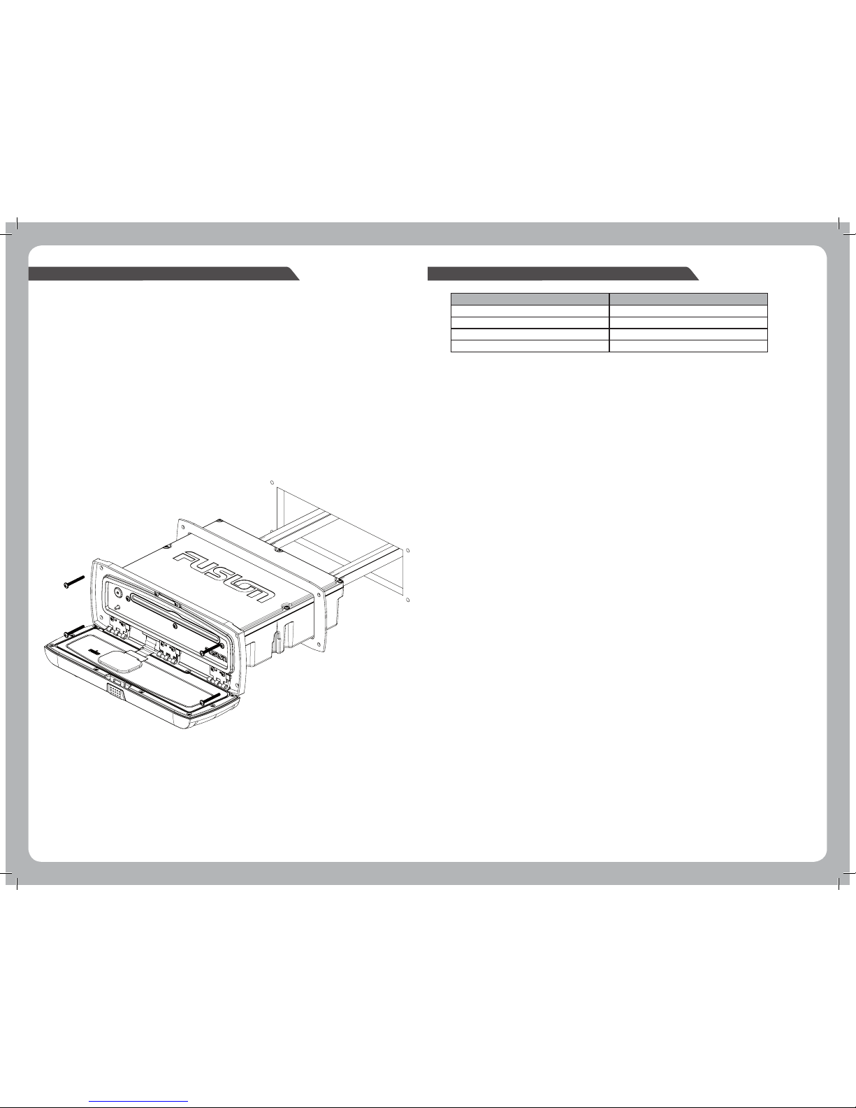
INSTALLATION
If any modification to the vessel is required, such as drilling holes, etc Fusion recommends consultation
with your boat dealer or manufacturer beforehand.
1. Remove the Sun cover from the unit
2. Insert the unit into the mounting hole
3. Pull down the front face to expose the mounting screw locations.
4. Use either the supplied 4 x wood screws, or 4 x machined screws and metal clamps to affix the
unit into position.
5. The unit must be mounted within 30 degrees of the horizontal plane.
Note: in some circumstances a back strap or brace may be required at the rear of the Unit,
(Back Strap / brace is not included)
ELECTRICAL WIRING
Caution: The MS-IP500 and MS-CD500 are designed for vessels with a 12Volt Negative ground electrical
system
POWER CONNECTIONS
ZONE CONNECTIONS
Zone 1 Speaker connection (2 Ohm Stereo minimum)
White = Speaker Left Positive
White / Black = Speaker Left Negative
Grey = Speaker Right Positive
Grey/ Black = Speaker Right Negative
Low level output( Connection to external amplifier required)
White RCA= Left Output
Red RCA = Right Output
Orange RCA= Subwoofer Output
Zone 2 Speaker connection (2 Ohm Stereo minimum)
Green = Speaker Left Positive
Green / Black = Speaker Left Negative
Purple = Speaker Right Positive
Purple / Black = Speaker Right Negative
Low level output (Connection to external amplifier required)
White RCA= Left Output
Red RCA = Right Output
Orange RCA= Subwoofer Output
Zone 3
Low level output (Connection to external amplifier required)
White RCA= Left Output
Red RCA = Right Output
Orange RCA= Subwoofer Output
Zone 4
Low level output (Connection to external amplifier required)
White RCA= Left Output
Red RCA = Right Output
Orange RCA= Subwoofer Output
Antenna Connection
Connect an AM/FM marine antenna.
AUX Input (Optional)
Connect an Auxiliary source to the left and right RCA
iPod Connection (MS-CD500 only)
Connect the 1.5 meter iPod accessories lead (not included - MS-IL500)
Connect the MS-IPDOCK (Not Included)
Sirius Satellite Radio (USA Only)
Connect to SiriusConnect(tm) tuner (not included)
Wired Remote MS-WR100
Connect the marine wired remote to the CANbus system connector cable.
DESCRIPTION COLOUR
Battery +12VDC Yellow
Accessory +12V switched Red
Negative Ground Black
Remote Amplifier Turn On Blue/White
Refer to the wiring diagram for reference
Appropriate mounting is very important to ensure correct operation. Select a location that allows both
free/open airflow around rear of chassis, whilst minimising exposure to moisture
Page 5

8
9
WIRING DIAGRAM
OPERATION
SELECTING A SOURCE
Press the desired source button:
Radio AM/FM/Sat
CD CD/MP3 (MS-CD500)
iPod/AUX Press once for iPod (MS-IP500)
Press twice for AUX (MS-CD500)
AUX Aux direct (MS-IP500)
ADJUSTING THE VOLUME
• Turn the to adjust the volume (Zone 1 Default)
ZONE VOLUME
• Press the to select zone. Press again to step through zones.
Zone 1 – All zones – Zone 2 – Zone 3 – Zone 4
GENERAL SETUP
• Press the and rotate the to select the Setup menu. Press to enter.
• Turn the to select the function and press to enter
• Turn the to adjust and press to return.
SETTINGS
Treble
Adjusts the treble to the speakers
Bass
Adjusts the bass to the speakers
Balance
Adjusts the audio balance from left to right
Contrast
Adjusts the display contrast.
Key Sound
Press to turn ON / OFF
AUX Configuration
AUX ON/OFF - Select OFF if no auxiliary device is connected, this will remove the AUX feature
from the source list.
AUX Name - Select the desired AUX name
AUX – TV – DVD – GAME – PORTABLE - COMPUTER
Clock Adjust
Adjusts the Clock time, 12/24 hour
Turn the to adjust the Hour, Press to confirm, repeat to adjust the minutes, Press to confirm.
The MS-CD500 and MS-IP500 features Clock battery back up and Eprom technology, This allows the unit
to be completely disconnected from the vessels +12volt Voltage supply (Battery switch) with No
settings lost.
Power
Press to turn the unit ON/OFF
Page 6

10
11
RADIO OPERATION
Regions (tuner regions Europe / USA)
Select Europe for the following tuner frequency stepping
FM Radio
Frequency Range: 87.5 – 108 MHz Frequency step: 100 kHz
AM Radio
Frequency Range: 522 – 1620 MHz Frequency step: 9 kHz
Select USA for the following tuner frequency stepping
FM Radio
Frequency Range: 87.5 – 107.9 MHz Frequency step: 200 kHz
AM Radio
Frequency Range: 530 – 1710 MHz Frequency step: 10 kHz
Note: Remember, whilst in the menu system the acts as a back/return to the previous menu screen.
Power save
Off = Backlight on
On = LCD backlight goes off after one minute of non-operation
Region Selection
Press and turn to select setup - Press to enter - turn the to select tuner region
Press to enter and press to select region
Band Selection
Press the to select band
FM – AM – SAT
Tuning
There are 15 presets available per band.
Seek Tuning
1. Press the
or to scan to the next station.
2. The selected station will be auto saved into the station presets menu.
Manual Tuning
1.Press and hold the
or for 3 seconds to enter. The manual tuning icon will flash on screen.
2.The selected station will be Auto saved into the presets menu.
Note: Once the station is selected the station will be stored into the pre-set menu and the manual tuning
icon will be removed.
Auto Tuning
Press the and turn the to navigate to the “Search Station” function. Then press to search and
store.
Note: Automatic tuning mode will erase all other presets already stored for the selected band and will
automatically store the station into the Preset menu in numerical order.
Recalling a Preset Station
1. Select the required band. FM -- AM -- Sat
SIRIUS SATELLITE RADIO - USA only - SIRIUS TUNER NOT INCLUDED
SIRIUS ACTIVATION
Activating Your Sirius Tuner
You must activate the SIRIUS tuner before you can begin to receive the SIRIUS Satellite Radio Service.
In order to activate your radio subscription, you will need the SIRIUS ID (SID) which uniquely identifies your
tuner. The 12 digit SID is displayed on the LCD on initialization. MS-CD500 and MS-IP500 will display the SID
on Channel 0.
Power on your system and make sure that you are receiving good signal you are able to hear audio on the
SIRIUS Preview channel (Ch-184)
Note:
Have your credit card handy and contact SIRIUS on the internet at https://activate.sirius.radio.com/ and follow the prompts to activate your subscription.
You can also call SIRIUS toll-free at 1-888-539-SIRIUS (1-888-539-7474) Once activated, you will be able to begin enjoying SIRIUS Satellite Radio’s digital
entertainment and can tune to other channels.
SIRIUS OPERATION
Press the to select Sat Radio
SIRIUS NAVIGATION
Press the and enter the menu, turn the to navigate the functions and press to select.
• Channels
Select the desired channel (listed in channel order) and music preference
• Category
Select the desired genre type. (The unit will only play the selected option)
• Favourites
Add your favourite channel to your favourites list by selecting “add favourite”.
(Maximum 15 channels)
Remove channels by selecting “Remove Favourite” select “ALL” or the individual channel and
push Enter
Exit MNU by pressing
• Parental Mode
Pin #
Turn
to select number and press to enter, repeat to enter the 4 digit code. (Default is 0 on 1st time use)
NOTE: Must be entered before the following items are operational.
Mode on/off
Turn On to initiate parental locking of selected channels etc, turn Off for full channel access
Lock / Unlock
Select the channel to be locked or unlocked
Skip / Un-skip
Select the channel to be bypassed from the menu
Change Pin
Personalise your Pin number. (4 digits max)
2. Press the and then turn the select the “Presets” option and press to enter.
3. Turn the
to select the desired preset and press to select
Page 7

12
13
CD/MP3 OPERATION
CONNECTING AN iPod (MS-CD500 only)
LOADING / EJECTING A CD OR MP3 (MS-CD500 ONLY)
Notes:
Never insert foreign objects into the CD slot.
If the CD does not insert easily, there may already be another CD in the unit. Some CD-R/CD-RW may not
be readable if the format is not compatible.
LISTENING TO A CD/MP3 ALREADY INSERTED
Press the CD button to select CD / MP3 mode. Playback of the CD will start automatically.
CD / MP3 FUNCTIONS
Catch Release Button Eject Button
BUTTON DESCRIPTION
CD
Press to access the CD/MP3 source
Play/Pause
Pause or Play the track
Back/Previous.
Short Press: Selects previous track
Press and hold: Rewind track
Forward/Next
Short Press: Selects next track
Press and hold: Fast-forward track
CD NAVIGATION
Press and turn the to select tracks ,turn the to select desired track and press
to confirm.
MP3 NAVIGATION
Note: The MP3 disc will take approx 10 seconds to load the disc data (if available) to the unit.
Press the and enter the MP3 root directory, turn the to navigate the functions of your MP3
folders and files.
Press to select the highlighted Folder or file.
Note: Press the to return to the previous menu screen.
REPEAT SONG
Press and turn the to select Repeat/Shuffle
Press the to select ON/OFF - default setting is OFF
SHUFFLE
Press and Turn the to select Repeat/Shuffle
Then press to select ON/OFF
Default setting is OFF
PRECAUTIONS FOR MP3
The format of the disc must be ISO9660 Level 1 or 2 or Joliet in the expansion Format
When naming an MP3 file, ensure the file extension is * .MP3
• Connect the iPod cable from the MS-CD500 to the iPod. (MS-IL500 Cable not included)
• Connect the MS-IPDOCK cable to the iPod connection on the MS-CD500
MS-IPDOCK (Not included)
Page 8

14
15
MS-IP500
Note:
Failure to correctly insert you iPod will result in damage to your iPod and the FUSION Marine Stereo.
Selecting the correct iPod Sleeve
The MS-IP500 has 8 possible iPod solutions.
A different set of sleeves is used for each iPod model. The different sleeve combinations are outlined in the
chart below:
Please note: For the iPod nano (3rd gen), the iPod must be placed inside the adaptor sleeve, and then
placed inside Dock sleeve combination A.
Please note: Place the sleeves inside the Stereo Unit before inserting your iPod.
LOADING / EJECTING AN IPOD (MS-IP500 ONLY)
Catch Release Button iPod Cradle Slot
IPOD NAVIGATION
Press the
to enter the iPod menu, use the to navigate the functions of your iPod. The rotary
encoder operates similar to the click wheel on your iPod. Turn to navigate and press to enter.
Note: Press the to return to the previous menu screen.
BUTTON DESCRIPTION
iPod.
Press to access the iPod source
Play/Pause
Play/Pause track in CD/MP3 and iPod mode.
Forward/Next
Short Press: To select the next track in CD/MP3 or iPod mode.
Press and hold: Fast-forward in CD/MP3 or iPod mode.
Back/Previous.
Short Press: To select the previous track in CD/MP3 or iPod mode
Press and hold: Rewind in CD/MP3 or iPod mode
CONNECTING AN AUXILIARY AUDIO DEVICE
1. The Left & Right AUX RCA plugs are located at the rear of the unit.
2. Connect your auxiliary audio device.
Note: You may require an adapter cable to connect your device.
LISTENING TO YOUR AUXILIARY AUDIO DEVICE
1. Press the on the main unit to select AUX mode (MS-IP500) or press twice (MS-CD500)
2. Start playback on your auxiliary audio device. Use both the volume control on your auxiliary device
(if available) and the volume control on the FUSION Marine Stereo to set the volume level.
AUXILIARY NAMING
See page 9
AUX OPERATION
NO iPod Connected
If this appears on the display possible causes are
1. Ensure the iPod is correctly connected
2. Ensure the cable is not excessively bent
3. The iPods battery remains low ( refer to iPod manual and charge the battery )
4. The iPods software version is not compatible (update software version to be compatible with this unit)
iPod Top sleeve Bottom sleeve
classic, 5th Gen (30gb) A A
classic, 5th Gen (60/80gb) A B
classic, 6th Gen (80gb) B A
classic, 6th Gen (160gb) B B
classic, 7th Gen B A
itouch, 1st Gen, 2nd Gen D D
nano, 2nd Gen C C
nano, 3rd Gen, + Adapter A A
nano, 4th Gen E E
Page 9

16
17
ZONE SET UP
The Marine Stereo can be configured to control specific audio zones on your boat. This zone can then be
turned ON/OFF separately to other zones.
Note: If the Zone is selected as “OFF” The features are not available,
1. Access the Zone Setup Menu by pressing the then turn the and press to select ‘ZONES’
2. Turn the to select the zone you wish to setup –
Zone 1 Zone 2 Zone 3 Zone 4
3. You can adjust the following settings for each zone in the Zone Setup menu, by using the
Zone ON/OFF
Select “On” if zones are present on the vessel (Z - 2, 3, 4)
Note: Zone 1 cannot be turned OFF
Volume Limit
Adjust the “Volume Limit” to the desired maximum Output volume setting to each individual Zone,
Sub Limit
Adjust the level of output for the subwoofer used in the zone
Low Pass (L/P) Filter
Adjust the Low pass Frequency output (Off, 50Hz, 80Hz, 120Hz) to the subwoofer used in the zone
High Pass (H/P) Filter
Adjust the High pass Frequency output (Off, 160Hz, 120Hz, 80Hz) to the Speakers
used in the zone.
ROOT MENU
Presets
0 ... 15
Search Stations
Disc
Track s
Repeat / shuffle
Zone 2
SUB Limit
Low Pass Filter
iPod
Playlists
Artists
Albums
Songs
Podcast s
Composers
Zone
Zone 1
Zone ON/OFF
Volume Limit
[iPOD Listing]
[MP3 Listing]
[iPOD Listing]
[iPOD Listing]
[iPOD Listing]
[iPOD Listing]
[iPOD Listing]
Setup
Trebl e
Bass
Balance
Contrast
Keysound
AUX con fig
Clock Adjust
Tuner Region
Audiobooks
Repeat/Shuffle
[iPOD Listing]
[iPOD Listing]
High Pass Filter
TUNER
CD
Disc
Root Folder
Repeat / shuffle
MP3
iPOD
SUB Limit
Low Pass Filter
Volume Limit
High Pass Filter
Zone 3
Zone ON/OFF
SUB Limit
Low Pass Filter
Volume Limit
High Pass Filter
Zone 4
Zone ON/OFF
SUB Limit
Low Pass Filter
Volume Limit
High Pass Filter
Power Save
LINK Zone 1 + 2
MENU STRUCTURE
LINK ZONE 1 + 2
Allows the volume control to operate zones 1 + 2 as a combined pair. The Zone set up for Zone 1 and 2
can be configured separately when in this mode.
1. Access the Zone Setup Menu by pressing the then turn the and press to select ‘ZONES’
2. Turn the and press to enter ‘zone 1’
3. Rotate and press the to select the “Link zone 1 + 2”
4. Select ON to activate this feature.
ZONE SETUP AND CONTROL
There are 4 configurable zones available on the FUSION Marine Stereo. Each zone has independent
volume control, subwoofer configuration, and balance control. Not all zones have to be configured,
for the unit to run.
Note: Zone one is the default and cannot be switched off
ZONE OPERATION
Page 10

18
19
LICENSING
Apple, the Apple logo, iPod and iTunes are Trademarks of Apple Computer, Inc.,
registered in the U.S. and other countries.
© 2007 SIRIUS Satellite Radio Inc. “SIRIUS” and the SIRIUS dog logo are trademarks of Sirius Satellite
Radio Inc. All rights reserved.
PRECAUTIONS
Handling Compact Discs (CD/CD-R/CD-RW)
• Avoid touching the surface of the disc
• Avoid exposing the disc to direct sunlight
• Ensure the disc is clean
• Ensure the disc is not scratched or damaged
Playback of CD-R/CD-RW
• If your CD-R/CD-RW will not play, Ensure that the last recording session was closed or finalized.
Supported Media
• Only use compact discs with the CD logo’s on the label as listed below.
• If you use compact discs without the above logo’s correct performance cannot be
guaranteed.
• You can play audio discs recorded on CD-R (Recordable) and CD-RW (Re Writable) media
• MP3 formatted audio files can also be played on CD-Rs and CD-RWs containing these files.
SPECIFICATIONS
Chassis Dimensions Depth 160mm - 6-5/16” Width 180mm – 7-1/8” Height 52mm – 2-1/16”
Face Plate Dimensions Depth 36mm – 1-7/16” Width 217mm – 8-9/16” Height 79mm – 3-1/8”
Operating Voltage: 10.2 – 16VDC Negative ground
Fuse rating: 15 Amp
Output power: 70 Watts x 4 (Max)
Speaker Impedance: 2 – 4 Ohms per channel
Pre –output Voltage: 2V
TUNING RANGE
Europe
FM Radio
Frequency Range: 87.5 – 108 MHz Frequency step: 100 kHz
AM Radio
Frequency Range: 522 – 1620 MHz Frequency step: 9 kHz
USA
FM Radio
Frequency Range: 87.5 – 107.9 MHz Frequency step: 200 kHz
AM Radio
Frequency Range: 530 – 1710 MHz Frequency step: 10 kHz
CD Player
Laser power Class 1
NOTES
PUBLISHED BY FUSION ELECTRONICS LIMITED:
© Copyright 2008 by FUSION Electronics Limited.
All rights reserved. Specifications and design are subject to change without notice.
YOU CAN HELP PROTECT THE ENVIRONMENT!
Please remember to respect the local regulations:
Hand in the non-working electrical equipment to an appropriate waste disposal center.
Page 11

 Loading...