

Page 1

OPERATOR'S MANUAL
INTEGRATED
HEADING SENSOR
Model
PG-700
www.furuno.com
Page 2

Page 3
IMPORTANT NOTICES
General
• This manual has been authored with simplified grammar, to meet the needs of the international
users.
• The operator of this equipment must read and follow the descriptions in this manual. Wrong operation or maintenance can cancel the warranty or cause injury.
• Do not copy any part of this manual without written permission from FURUNO.
• If this manual is lost or worn, contact your dealer about replacement.
• The contents of this manual and equipment specifications can change without notice.
• The example screens (or illustrations) shown in this manual can be different from the screens
you see on your display. The screens you see depend on your system configuration and equipment settings.
• Save this manual for future reference.
• Any modification of the equipment (including software) by persons not authorized by FURUNO
will cancel the warranty.
• All brand and product names are trademarks, registered trademarks or service marks of their
respective holders.
How to discard this product
Discard this product according to local regulations for the disposal of industrial waste. For disposal
in the USA, see the homepage of the Electronics Industries Alliance (http://www.eiae.org/) for the
correct method of disposal.
How to discard a used battery
Some FURUNO products have a battery(ies). To see if your product has a battery, see the chapter
on Maintenance. Follow the instructions below if a battery is used. Tape the + and - terminals of
battery before disposal to prevent fire, heat generation caused by short circuit.
In the European union
The crossed-out trash can symbol indicates that all types of batteries
must not be discarded in standard trash, or at a trash site. Take the
used batteries to a battery collection site according to your national
legislation and the Batteries Directive 2006/66/EU.
In the USA
The Mobius loop symbol (three chasing arrows) indicates that Ni-Cd
and lead-acid rechargeable batteries must be recycled. Take the
used batteries to a battery collection site according to local laws.
Cd
Ni-Cd Pb
In the other countries
The Mobius loop symbol (three chasing arrows) indicates that Ni-Cd and lead-acid rechargeable
batteries must be recycled. Take the used batteries to a battery collection site according to local
laws.
i
Page 4
SAFETY INSTRUCTIONS
Read these safety instructions before you operate the equipment.
Indicates a condition that can cause death or serious injury if
WARNING
CAUTION
Warning, Caution
not avoided.
Indicates a condition that can cause minor or moderate injury if
not avoided.
Prohibitive Action
Mandatory Action
Instructions for the installer
WARNING
Turn off the power at the mains switchboard before beginning the installation.
Post a sign near the power switch
indicating it should not be turned while
the equipment is being installed.
Fire, electrical shock or serious injury can
result if the power is left on or is applied
while the equipment is being installed.
Use specified cable to connect the
Junction Box.
Use of the wrong cable can result in
bodily injury and cause fire.
CAUTION
Be sure to connect to the correct
power supply.
Instructions for the user
WARNING
Turn off power at the switchboard if the
equipment is emitting smoke or fire.
Fire or electrical shock can result if the
power remains on
Turn off the power at the switchboard
if you feel the equipment is not
working properly.
If the equipment feels hot or is emitting
odd noises, immediately turn off the power
at the switchboard.
Do not dissassemble or modify the
equipment.
Fire, electrical shock or bodily injury
can result.
Connection to a wrong power supply
can cause fire or bodily injury.
Observer the following compass safe
distances to prevent interference to
a magentic compass.
Std. Compass Steering compass
0.3 m 0.3 m
Before doing deviation correction
and heading adjustment, turn off
the autopilot.
The rudder may jerk violently, which
can result in a dangerous situation.
ii
Page 5

TABLE OF CONTENTS
FOREWORD................................................................................................................... iv
SYSTEM CONFIGURATION ...........................................................................................v
EQUIPMENT LIST .......................................................................................................... vi
1. HOW TO INSTALL THE EQUIPMENT ..................................................................... 1
1.1 Installation Considerations ............................................................................................1
1.2 Wiring ............................................................................................................................6
1.3 Compensation of Deviation ...........................................................................................9
1.4 Heading Adjustment ....................................................................................................11
1.5 Input/Output Data List..................................................................................................13
2. OPERATION ........................................................................................................... 14
2.1 Key and Lamp Explanation..........................................................................................14
2.2 How to Turn on the PG-700 ........................................................................................15
3. MAINTENANCE AND TROUBLESHOOTING........................................................ 16
3.1 General Maintenance ..................................................................................................16
3.2 Lamp status display ....................................................................................................16
3.3 Troubleshooting ..........................................................................................................18
3.4 How to restore default settings....................................................................................18
Specifications...........................................................................................................SP-1
Outline Drawings........................................................................................................ D-1
Interconnection Diagram........................................................................................... S-1
iii
Page 6

FOREWORD
Congratulations on your choice of the PG-700 Integrated Heading Sensor. We are confident you
will see why the FURUNO name has become synonymous with quality and reliability.
Since 1948, FURUNO Electric Company has enjoyed an enviable reputation for innovative and
dependable marine electronics equipment. This dedication to excellence is furthered by our extensive global network of agents and dealers.
Your equipment is designed and constructed to meet the rigorous demands of the marine environment. However, no machine can perform its intended function unless properly operated and
maintained. Please carefully read and follow the operation and maintenance procedures set forth
in this manual.
Features
• Angular velocity sensor and magnetic bearing sensor incorporated.
• Automatic determination of installation site suitability.
• L-shaped mounting base for mounting on bulkhead.
• Output of magnetic bearing data to FURUNO CAN bus device.
iv
Page 7
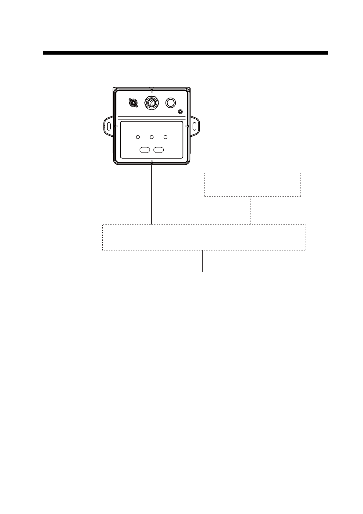
SYSTEM CONFIGURATION
The solid line below shows the basic system configuration.
SENSOR
PG-700
FURUNO CAN bus Device*
JUNCTION BOX
FI-5002
12 VDC**
*: NavNet 3D, FI series instrument, etc.
**: Not necessary if FURUNO CAN bus network supplies power.
v
Page 8
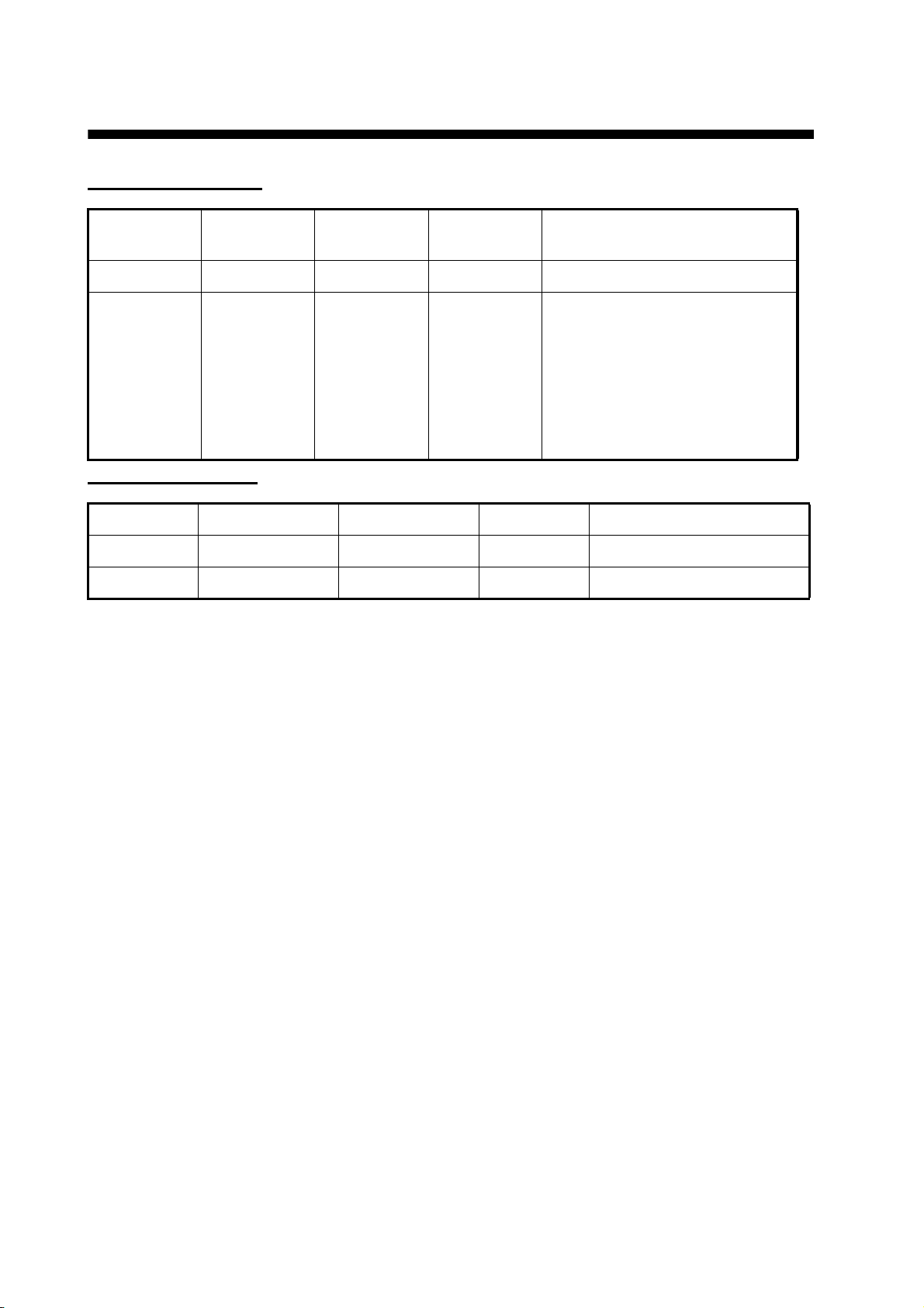
EQUIPMENT LIST
Standard Equipment
Name Model
Sensor PG-700 - 1
Installation
materials
CP64-02800 - 1 set • Cable set
Code
number
Quantity Remark
Type: M12-05BM+05BF-060
Code number: 000-167-964-11
Quantity: 1
• Self-tapping screws
Type: 4x16 SUS304
Code number: 000-162-605-10
Quantity: 3
Optional Equipment
Name Model Code number Quantity Remark
Junction box FI-5002 000-010-765 1 set
Cable set FI-50-DROP-6M 001-105-810-10 1 6m
vi
Page 9

1. HOW TO INSTALL THE EQUIPMENT
1.1 Installation Considerations
Mount the unit with the lamps and keys face up on a horizontal surface. The unit can be mounted
on a desktop or bulkhead. Overhead mounting is not allowed. When selecting a mounting location,
observe the following to ensure optimal performance:
• Do not mount in an area where water can collect.
• Mount the unit in an area with a temperate between -15 and +55 °C (5 -131°F).
• Mount the unit in an area with low shock and vibration (near the center of gravity to the hull as
possible).
• Mount far away from any electromagnetic wave sources (radio antennas, etc.).
• Mount horizontally, and not on the ceiling.
• Mount as far away as possible from any magnetic interference and power cables.
• Mount at least 50cm (20”) away from the following:
• Engines, generators, steel fuel and water tanks
• Bilge pump, anchor, anchor chain
• Radio antenna cables
• Metal mast support and keel
• Mount in a location where it is easy to adjust or perform maintenance.
• Mount close to the ship’s draft (do not mount to the mast or Tuna tower).
1
Page 10
1. HOW TO INSTALL THE EQUIPMENT
Determining the mounting location
After choosing the approximate mounting location to a table or bulkhead, ensure that the location
is suitable to supply power to the unit.
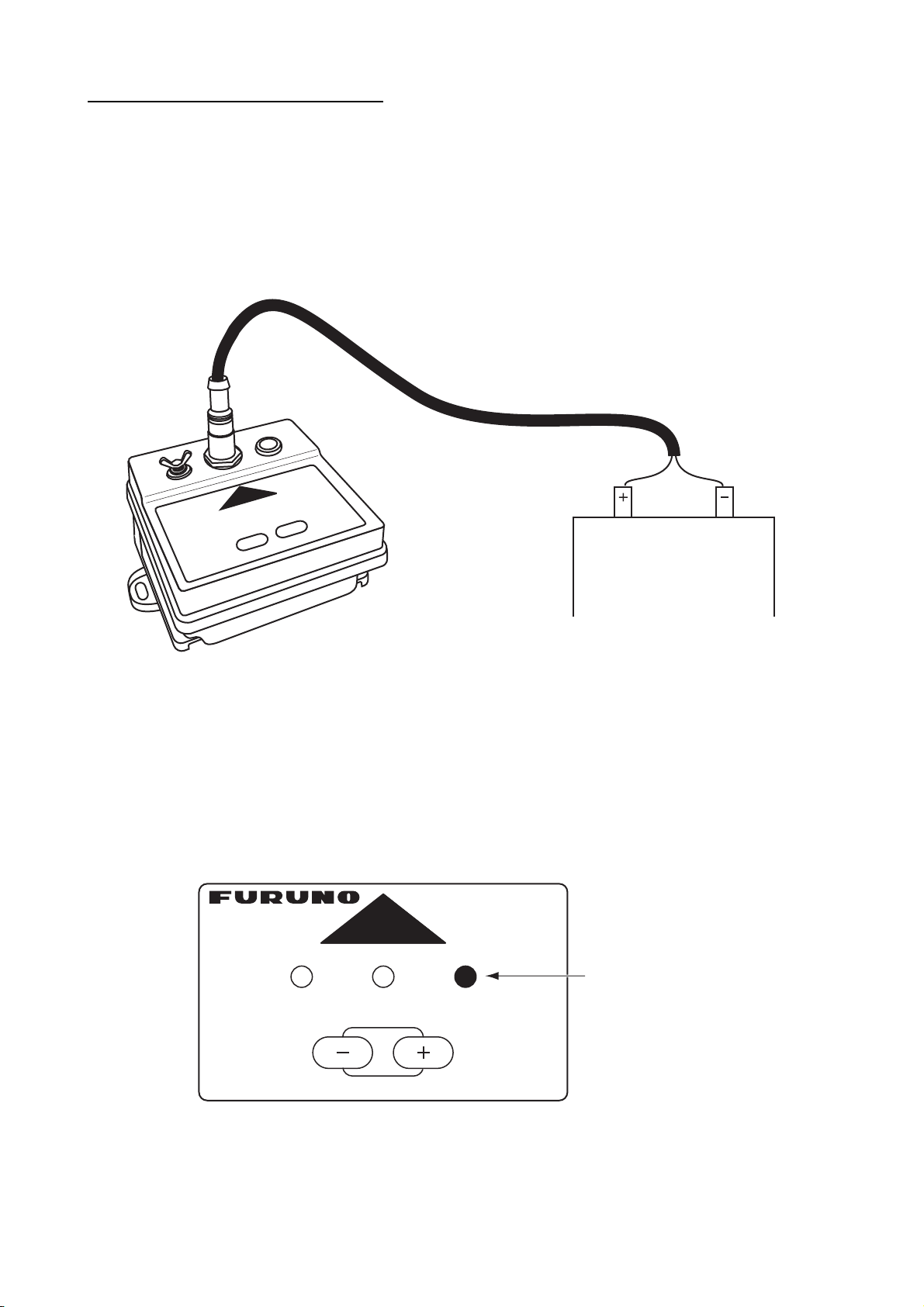
1. Connect the power cable to the unit.
If the sensor unit is connected last to the optional Junction Box FI-5002, cut off the connector
(supplied) of the cable M12-05BM+05BF-060 from the FI-5002 side, and connect the red wire
of the cable to the positive terminal (+) of the battery (12 VDC) and the black wire to the negative terminal (-).
Red Black
Ship's Switchboard
Battery
12 VDC
If you connect PG-700 directly to the instrument, or to a network, each device must be temporarily connected to each other, and a power supply 12 VDC (see page 6).
2. Place the unit at the intended mounting position and supply power. Verify that the STATUS
lamp is not lit red.
If the STATUS lamp illuminates red, there may be a problem with the internal magnetic sensor.
3. Press and hold the [+] and [-] keys simultaneously for seven seconds, and release both keys.
The CHECK lamp blinks, and the CALIB and STATUS lamps turn off.
THIS SIDE UP
PG-700
BOW
CALIB STATUS CHECK
Flashing (green)
2
Page 11
1. HOW TO INSTALL THE EQUIPMENT
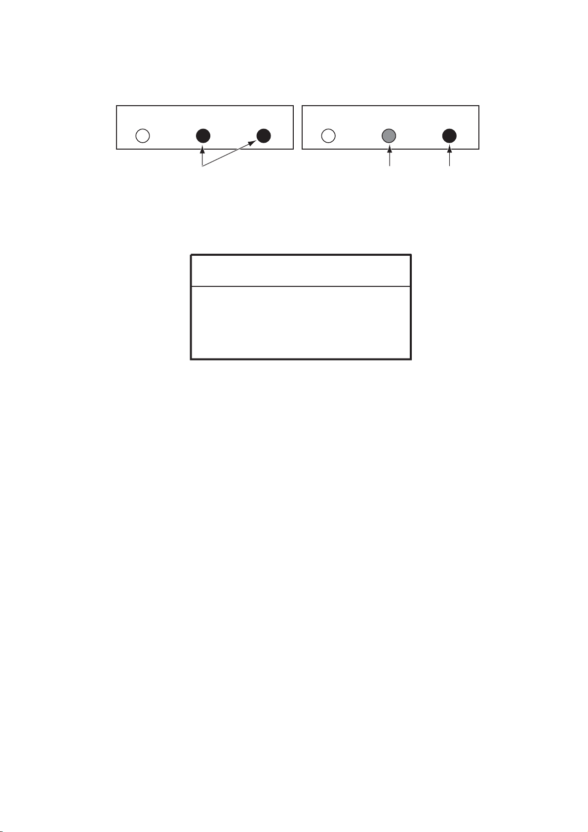
4. Slowly turn the unit (one turn per minute) at the mounting position (turn one - two times to
achieve the results as shown in the left figure below).
If successful, the STATUS and CHECK lamps light green. If fails, the STATUS lamp lights red.
CALIB STATUS CHECK CALIB STATUS CHECK
On (green)
(a) Installation site OK
If you interrupt the unit operation, press and hold the [+] and [-] keys simultaneously for three
seconds.
(b) Installation site no good
On (red)
On (green)
NOTICE
This location check procedure requires
only 90 seconds or less to complete.
If STATUS and CHECK lamps light green, fix
the unit to the acceptable location properly.
5. If fails, press and hold the [+] and [-] keys simultaneously for 3 seconds. Change the location,
and repeat steps 3 - 4 as above.
6. If successful, disconnect the power cable and follow the next steps to mount the unit firmly.
3
Page 12

1. HOW TO INSTALL THE EQUIPMENT
Tabletop mounting
Fix the unit with two self-tapping screws, facing the bow mark on the unit toward the bow (within
±10°) of the vessel. The long and round holes on the unit allow you to fine tune the direction of the
unit. See the outline drawing at the back of the manual for dimensions.
Self-tapping screws (supplied) (4x16)
BOW
BOW mark
4
Page 13

1. HOW TO INSTALL THE EQUIPMENT
Bulkhead mounting
The unit can be mounted to the bulkhead either parallel or vertical to the bow.
1. Remove two screws at the bottom to detach the mounting base.
2. Remount the base upside down using the two screws which were unscrewed in the above
step. It is possible to mount the unit in any horizontal direction in 90° steps. Mount the unit so
that the bow mark faces in the direction of the ship’s bow.
BOW
BOW mark
Mounting base
3. Fix the mounting base to the bulkhead with three self-tapping screws supplied.
Mounting
base
Self-tapping screw (4x16, 3 pcs.)
1
Notched
hole
2
Long round hole
1) Insert one screw in the place for the notched hole, halfway.
2) Set the notched hole in the center of the mounting base to the screw inserted into the bulkhead at step 1. Set a self-tapping screw in the long round hole. Adjust the mounting base
so it is horizontal and then tighten the self-tapping screws in the long round hole, and the
notched hole, in that order.
3) Fasten the remaining left self-tapping screw.
5
Page 14

1. HOW TO INSTALL THE EQUIPMENT
1.2 Wiring
Connect a termination resistor at both ends of the backbone of CAN bus devices. PG-700 incorporates a termination resistor. Turn the switch on/off as applicable.
If using the optional Junction Box FI-5002
Connect the unit and the FI-5002 using cable M12-05BM+05BF-060 (supplied as installation materials). For connection at the FI-5002, cut the cable at the pre-connected connector, fabricate the
cable as shown below, then connect the cable to the MC connector at the FI-5002. Ground the
unit to the hull using the shortest IV-2sq cable possible.
Crimp-on lug
(inner dia. 3mm)
To ground
*2
Ground wire*2
IV-2sq
*1: Turn the Termination switch
OFF to connect CN3 - CN5;
ON to connect CN2.
*2: Prepared locally
M12-05BM+05BF-060 (6m)
Termination switch*1
FI-5002
Power cable (2m)
Red
Sensor
PG-700
Black
–
+
12VDC
Fix cable with
supplied cable ties.
12VDC
Connect to
CN2 - CN5.
CN3 - CN5
DROP
MC connector
JUNCTION BOX
FI-5002 (option)
• How to fabricate cable M12-05BM+05BF-060 and connect MC connector
Side view
CN2
BACKBONE
Top view
Core
6 mm
Cable Fabrication
Twist
MC connector
Drain wire
Sheath
Screw
Wire Conn. Pt.
Drain 1
RED 2
BLK 3
WHT 4
BLU 5
How to insert cores:
1. Twist core.
2. Unfasten screw with flathead screwdriver.
3. Set core to hole.
4. Tighten screw.
5. Pull wire to confirm connection.
6
Page 15

1. HOW TO INSTALL THE EQUIPMENT
If connecting directly to the instrument
When connecting FI-502/FI-504/FI505 instruments, use supplied cable M12-05BM+05BF-060.
Do not cut the cable. Turn on the PG-700 termination switch.
M12-05BM+05BF-060
(Connector at both
ends, 6 m cable)
FI-50-DROP-6M
Ground
wire
SENSOR
PG-700
Termination switch
ON
Lamp ON
Instrument
FI-503/504/505/506/507
(Rear view)
cable (6 m)
Black
–
12 VDC
Red
+
If connecting to NavNet 3D network
• If connecting M12-05BM+05BF-060 as a drop cable to a T-type connector below, turn the termination switch off.
GOTO
S
O
R
U
R
C
Ground
wire
Termination
switch OFF
Lamp OFF
Example: NavNet 3D
M12-05BM+05BF-060
(connector at both ends,
6 m cable)
T-type connector T-type connector
POINTS
ROUTE
CTRL
SAVE
MOB
LIST
CANCEL
DISP
DATA
VOL
GAIN
MENU
TX
OUT
RANGE
IN
L
O
L
R
I
N
C
G
S
SHIP
3D
7
Page 16

1. HOW TO INSTALL THE EQUIPMENT
r
• If connecting M12-05BM+05BF-060 cable to a T-type connector as a backbone, as shown below, turn the termination switch on.
Termination switch ON
Lamp ON
GOTO
S
O
R
U
R
C
Ground
wire
FI-50
UPPER
DIGITAL
MIDDLE
LOWER
CAL
ADJ
SELECT
CLER
BRILL
Example: Instrument Example: NavNet 3D
T-type connectorT-type connector
LIST
POINTS
ROUTE
DATA
CANCEL
VOL
GAIN
DISP
MENU
TX
OUT
RANGE
IN
L
O
L
R
CTRL
I
N
C
G
S
SHIP
3D
SAVE
MOB
Terminator resisto
Termination switch
This switch is set according to the network topology. Generally, turn on the switch at the end of
the backbone cable. When ON, the lamp lights green.
8
Page 17

1. HOW TO INSTALL THE EQUIPMENT
1.3 Compensation of Deviation
The unit’s magnetic sense of direction may be affected by the metal of the vessel (including engines and power cables) as well as metal machinery or equipment on board. This discrepancy between true magnetic north and the indication of the unit is called “deviation”. Deviation may cause
incorrect heading data. The unit has the ability to automatically correct the deviation.
Note: In order to ensure the correct output orientation to a connected device, be sure to correct
the deviation.
CAUTION
Before doing the compensation of
deviation, turn off the autopilot.
The rudder may jerk violently if the
autopilot is powered, creating a
dangerous condition.
After finishing the installation completely, do the compensation of deviation in calm sea conditions
as follows:
1. Turn the PG-700 on and verify that the STATUS lamp is not lit red.
2. Press and hold the [+] and [-] key together for 3 seconds, and release both keys.
Deviation correction starts. The CALIB lamp flashes, and the STATUS and CHECK lamps
turn off.
CALIB STATUS CHECK
3. Turn the ship in as accurate a circle as possible, at a constant speed.
Steer in a controlled circle at approx. three knots, for about two minutes. It does not matter if
you turn in a left or right direction.
Run circle in two minutes
at speed of appox. three knots.
: Flashing (green)
: OFF
Note 1: Turning too fast may cause a large bearing error after the deviation correction.
Note 2: Be sure not to turn off the power to the switchboard when fixing deviation. Damage
of data may occur.
4. Continue turning until deviation correction is completed (about 3 to 5 turns).
When deviation correction is successful, the CALIB and STATUS lamps light for five seconds
and the initialization of the angular velocity sensor starts. After all lamps light, go to step 6.
9
Page 18

1. HOW TO INSTALL THE EQUIPMENT
A
Note: When doing deviation correction, the surrounding environment and ship position will
have an effect on the time it takes to succeed in the correction.
: ON (green)
: OFF
: Flashing (green)
t start of initialization of
angular velocity sensor
CALIB STATUS CHECK
After five sec.
CALIB STATUS CHECK
After two min.
CALIB STATUS CHECK
Initialization completed
(Normal condition)
Successful status for deviation correction
If deviation correction fails, the CALIB lamp lights green and the STATUS lamp lights red. The
deviation correction results remain until you proceed to step 5.
CALIB STATUS CHECK
: ON (green)
: ON (red)
: OFF
Failed status for deviation correction
5. If deviation correction fails, press the [+] and [-] keys simultaneously for 3 seconds to repeat
the process again from the beginning.
6. Anchor the vessel to a quay. Point the vessel toward a stationary object (lighthouse, etc., a
bearing which you can confirm on a nautical map) and confirm the bearing indication is correct. If it is not correct, measure the difference correctly and go to the procedure in section 1.4.
10
Page 19

1. HOW TO INSTALL THE EQUIPMENT
1.4 Heading Adjustment
The amount of adjustment required for the heading depends on the outcome of the previous section [1.3 Compensation of Deviation]. Do the following to correct the discrepancy.
CAUTION
Before doing the heading adjustment, turn off the autopilot.
The rudder may jerk violently if the
autopilot is powered, creating a
dangerous condition.
1. Press the [+] or [-] key. All lamps flash green and the unit enters heading adjustment mode.
CALIB STATUS CHECK
Note: Perform step 2 within five seconds. Heading adjustment mode stays active for 5 seconds after the key is pressed. If you do nothing, the unit returns to normal mode automatically.
2. Use the [+] or [-] key to adjust the difference between the sensor output heading and the actual
heading.
Heading can be adjusted at intervals of 0.1° or 1.0°. (see table below).
Key Set interval Lamp Status
Short press [-] key within 5 seconds
-0.1°
(decreases 0.1°
with every press)
Each time you press the [-] key, the STATUS lamp
will light on and off.
: Flashing (green)
CALIB STATUS CHECK
st time
CALIB STATUS CHECK
nd time
CALIB STATUS CHECK
3rd time
Long press [-] key within 5 seconds
-1.0°
(decreases in 1.0°
increments while
key is pressed)
Repeats
CALIB STATUS CHECK
11
Page 20

1. HOW TO INSTALL THE EQUIPMENT
Key Set interval Lamp Status
Short press [+] key
within 5 seconds
Long press [+] key
within 5 seconds
+0.1°
(increases 0.1°
with every press)
+1.0°
(increases in 1.0°
increments while
key is pressed)
Each time you press the [+] key, the STATUS lamp
will light on and off.
CALIB STATUS CHECK
1st time
CALIB STATUS CHECK
2nd time
CALIB STATUS CHECK
3rd time
Repeat
CALIB STATUS CHECK
: ON (green) : Flashing (green) : OFF
For example, in the case that the bearing displayed on a instrument connected to the unit is
70°, and the actual bearing is 75°, there is a 5° difference. To set to +5°, press and hold the
[+] key.
3. To exit heading adjustment mode, do not press any key for five seconds. The unit automatically returns to normal status.
Note: Press and hold the [+] and [-] keys for approx. one second at the lamp status after step 1 to
reset to 0.
Correction
value
resets to 0
Normal
condition
CALIB STATUS CHECK
Each lamp flashes
several times
CALIB
STATUS CHECK
: Flashing (green)
: Flashing (red)
: ON (green)
12
Page 21

1.5 Input/Output Data List
This unit uses the following input/output data
1. HOW TO INSTALL THE EQUIPMENT
Input/
output
Input
Output
Specification Remark
ISO request (PGN: 059904) PGN send request
Address claim (PGN: 060928) Address request
Self Test Group Function (PGN: 061184) Self test request
Memory Clear Group Function (PGN: 126720) Corresponding to clear all
Reset Group Function (PGN: 126720) Corresponding to reset all
NMEA-Request Group Function (PGN: 126208)
NMEA-Command Group Function (PGN: 126208)
+ (PGN: 130818, #4)
+ (PGN: 065283, #4, #5, #6, #7)
Vessel Heading (PGN: 127250)*1
Magnetic Compass Status (PGN: 065284)*2
ISO Acknowledgement (PGN: 059392)
ISO Request (PGN: 059904)
Address Claim (PGN: 060928)
NMEA Acknowledge (PGN: 126208)
PGN List (PGN: 126464)
Product Information (PGN: 126996)
Self Test Report (PGN: 130816)*2
Heading & Attitude Sensor Control Status (PGN:
130818)*2
Unit Division Code (PGN: 130822)*2
Browser Control Status (PGN: 130823)*2
Magnetic Compass Control Status (PGN: 065283)*2
Rate Gyro Data (PGN: 065285) *1*2
GMM Message (PGN: 126720, #4=4)*2
Input bearing adjustment
Change setting
Specific setting
Regular output.
100 ms (default)
1sec.
Irregular output. (Send only
when there is a request during
startup and changes). Displays each setting
PGN: Parameter Group Number. Equivalent to NMEA0183 sentence.
*1: Data can be output at an interval of 25ms and over (5ms steps) according to the request from
another device.
*2: PGN registered to Furuno Electric Co. Ltd.
13
Page 22

2. OPERATION
Before operating:
• This unit contains magnetic components. Keep away from metals (when the ship inclines, be
sure no metal objects roll towards the PG-700).
• When navigating in the vicinity of large structures (bridges, etc.), an bearing error may occur.
• If the distance between the unit and metal objects or magnets changes, an error may occur. In
that case, the deviation correction may have to be set again (see section 1.3).
• Do not disconnect power when using the automatic steering system.
2.1 Key and Lamp Explanation
THIS SIDE UP
PG-700
CALIB STATUS CHECK
BOW
Lamp Lamp state Color Key Function
CALIB These lamps
turn on, off, or
flash with
STATUS Green, Red • Push together for three seconds to
CHECK Green • Push either key to get to the Head-
Termination switch
The termination switch is turned on or off at installation. DO NOT change the setting.
equipment
state. (See
section 3.2)
Green • Push together for seven seconds to
determine suitability of installation
location.
start deviation correction.
ing adjustment mode.
Termination switch
14
Page 23

2. OPERATION
2.2 How to Turn on the PG-700
The unit has no power switch. Supply the +12 VDC power via the optional junction box FI-5002 or
FURUNO CAN bus device. When power is received by the sensor, the unit will automatically
check ROM and RAM status. After this, the lamps light as shown below:
CALIB STATUS CHECK
CALIB STATUS CHECK
CALIB STATUS CHECK
CALIB STATUS CHECK
: ON (green)
: ON (red/green)
: OFF
: Flashing (green)
CALIB STATUS CHECK
Angular velocity sensor initialization
(Approx. two minutes)
CALIB STATUS CHECK
Normal display
Note: If there is a problem with the ROM and/or RAM, the CALIB and CHECK lamps turn off, and
the STATUS lamp flashes red. Contact your dealer.
15
Page 24

3. MAINTENANCE AND TROUBLE-
SHOOTING
This chapter discusses maintenance and troubleshooting procedures to ensure optimal performance of the equipment.
NOTICE
D
o not apply paint, anti-corrosive
sealant or contact spray to plastic
parts or equipment coating.
Those items contain products that can
damage plastic parts and equipment
coating.
3.1 General Maintenance
To maintain full performance of the equipment, periodic inspection is required. Refer to the following table:
Inspection
item
Cable Check that cable is secure-
ly connected and there is
no rust or corrosion.
Ground Terminal
Sensor Unit Make sure the unit is free of
Ensure the ground terminal
is free of rust and not loose.
dust and dirt.
Checkpoint Action
If necessary, reconnect the cable or replace if damaged.
Tighten the terminal and clean off rust.
Wipe off dust and dirt with a soft, dry cloth. You may
use a cloth moistened with a diluted detergent. Do
not use thinner, acetone, alcohol, benzene, or any
plastic solvent, as they may remove markings from
the panel.
3.2 Lamp status display
Lamp Status Unit operating condition
CALIB STATUS CHECK
Normal state
• Deviation correction: success
• Angular velocity sensor: initialization complete
16
Page 25

Lamp Status Unit operating condition
CALIB STATUS CHECK
CALIB STATUS CHECK
CALIB STATUS CHECK
CALIB STATUS CHECK
3. MAINTENANCE AND TROUBLESHOOTING
• Deviation correction: success
• Angular velocity sensor: initializing
• Deviation correction: not implemented (or failed)
• Angular velocity sensor: initialization complete
• Deviation correction: not implemented (or failed)
• Angular velocity sensor: initializing
• Deviation correction: success
• Angular velocity sensor: failure
• Heading data output of the magnetic sensor only
Light alternately.
CALIB STATUS CHECK
Light alternately.
CALIB STATUS CHECK
• Deviation correction: not implemented (or failure)
• Angular velocity sensor: failure
• Heading data output of the magnetic sensor only
• Magnetic bearing sensor: failure
• No output of magnetic bearing data
: ON (red): ON (green)
: OFF
: Flashing (green)
17
Page 26

3. MAINTENANCE AND TROUBLESHOOTING
3.3 Troubleshooting
If a problem occurs, first do the following inspections. If the problem persists, contact the dealer
or a qualified service technician.
Problem Action
Lamps do not light. • Check to ensure the connector is tightened.
• Check to ensure the cable is not corroded.
• Check to ensure the cable is not damaged.
• Check that the routing of the power supply is functioning properly.
Red lamp is on. Turn the power on and off several times. If the red lamp remains
lit, contact your dealer.
No magnetic bearing data. • Turn the power on and off several times. If the problem persists,
contact your dealer.
• Check the terminal switch.
3.4 How to restore default settings
You can revert the unit to factory settings by doing the following:
1. Disconnect the cable from the unit.
2. Press and hold the [-] key, and reconnect the cable. Continue pressing the [-] key until step 3
is completed. Power is applied to the unit, all lamps flash. When initialization is completed, all
lamps light.
After power
CALIB STATUS CHECK
is applied
Each lamp flashes
several times
Initialization
completed
3. When all lamps light, stop pressing the [-] key.
4. To return to normal state, reconnect the unit cable.
CALIB STATUS CHECK
: Flashing (green)
: Flashing (red/green)
: ON (green)
: ON (red/green)
18
Page 27

FURUNO
SPECIFICATIONS OF INTEGRATED HEADING SENSOR
PG-700
1 GENERAL
1.1 Heading Accuracy ±1.0° (horizontal)
±10.0° (within 30°), ±20.0° (within 45°)
1.2 Display resolution 0.1°
1.3 Follow-up 100°/s rate-of turn
1.4 Interface CAN bus: 1 channel
Output PGN 126720
Input settings Output interval, Bearing offset
1.5 Data Update 25 ms max. (default: 100 ms)
1.6 Delay Within 75 ms
2 POWER SOURCE
PG-700
12 VDC: 0.1 A (LEN: 3)
3 ENVIRONMENTAL CONDITION
3.1 Ambient Temperature -15°C to +55°C
3.2 Relative Humidity 95% at 40°C
3.3 Waterproof IP55 (IEC 60529), CFR-46 (USCG standard)
3.4 Vibration IEC 60945
4 UNIT COLOR
N3.0
SP - 1 E7276S01A
Page 28

This page is intentionally left blank .
Page 29

D-1
4/Sep/09R.Esumi
Page 30

D-2
4/Sep/09R.Esumi
Page 31

PG-700
S-1
ハイブリッドヘディングセンサー
相互結線図
INTEGRATED HEADING SENSOR
43
INTERCONNECTION DIAGRAM
PG-700
SHIELD
NET-S
NET-C
CAN BUS
ハイブリッドヘディングセンサー
INTEGRATED HEADING SENSOR
12345
-SR7000
LTW12-05AFFM
RED
BLK
アカ
クロ
M12-05BM+05BF-060,6m,φ6(*3)
FI-50-DROP,6m,φ6(*2)
NET-H
NET-L
WHT
BLU
シロ
アオ
*1
IV-2sq.
CANバスネットワーク機器
CAN bus DEVICE
同上
DITTO
同上
DITTO
同上
DITTO
同上
DITTO
TITLE
DRAWN
名称
T.YAMASAKI
T.TAKENO
8/Mar/10R.Esumi
28/Jan/10
28/Jan/10
CHECKED
APPROVED
NAME
64-031-5000-0
REF.No.
kg
C7276-C01- B
DWG.No.
SCALE MASS
12345
12345
12345
12345
12345
12345
2
NET-S
NET-C
NET-H
NET-S
NET-C
接続箱
JUNCTION BOX
NET-L
NET-H
NET-L
(BACKBONE)
CAN bus NETWORK
NET-S
NET-C
NET-H
NET-L
SHIELD
CN3 DROP_LCN2 BACKBONE_U
SHIELD
12345
ジャンクションボックス
JUNCTION BOX
SHIELD
CN3 DROP_U
*2
CN1 12VDC
FI-5002
(+)
(-)
123
BLKクロ
シロ WHT
SHIELD
1
(VV-SA0.75x2C)
FI-5002-POWERCABLE,2m
12VDC
A
NET-S
SHIELD
CN4 DROP_U
SHIELD
NET-S
12345
CN2 BACKBONE_L
接続箱
JUNCTION BOX
NET-C
NET-H
NET-C
NET-H
CAN bus NETWORK
NET-L
NET-L
(BACKBONE)
SHIELD
CN4 DROP_L
NET-S
NET-C
NET-H
NET-L
B
SHIELD
CN5 DROP_U
NET-S
NET-C
NET-H
NET-L
SHIELD
CN5 DROP_L
NET-S
NET-C
NET-H
NET-L
NOTE
*1: SHIPYARD SUPPLY.
注記
*1)造船所手配。
*2)オプション。
*3)コネクタを切り離して接続する。
*2: OPTION.
*3: REMOVE THE CONNECTOR FOR FABRICATION.
C
Page 32

FURUNO Worldwide Warranty for Pleasure Boats (Except North America)
This warranty is valid for products manufactured by Furuno
Electric Co. (hereafter FURUNO) and installed on a pleasure
boat. Any web based purchases that are imported into other
countries by anyone other than a FURUNO certified dealer may
not comply with local standards. FURUNO strongly recommends
against importing these products from international websites as
the imported product may not work correctly and may interfere
with other electronic devices. The imported product may also be
in breach of the local laws and mandated technical requirements.
Products imported into other countries as described previously
shall not be eligible for local warranty service.
For products purchased outside of your country please contact
the national distributor of Furuno products in the country where
purchased.
This warranty is in addition to the customer´s statutory legal
rights.
1. Terms and Conditions of Warranty
FURUNO guarantees that each new FURUNO product is the
result of quality materials and workmanship. The warranty is
valid for a period of 2 years (24 months) from the date of the
invoice, or the date of commissioning of the product by the
installing certified dealer.
2. FURUNO Standard Warranty
The FURUNO standard warranty covers spare parts and labour
costs associated with a warranty claim, provided that the product
is returned to a FURUNO national distributor by prepaid carrier.
The FURUNO standard warranty includes:
Repair at a FURUNO national distributor
All spare parts for the repair
Cost for economical shipment to customer
3. FURUNO Onboard Warranty
If the product was installed/commissioned and registered by a
certified FURUNO dealer, the customer has the right to the
onboard warranty.
The FURUNO onboard warranty includes
• Free shipping of the necessary parts
• Labour: Normal working hours only
• Travel time: Up to a maximum of two (2) hours
• Travel distance: Up to a maximum of one hundred
and sixty (160) KM by car for the complete journey
4. Warranty Registration
For the Standard Warranty - presentation of product with serial
number (8 digits serial number, 1234-5678) is sufficient.
Otherwise, the invoice with serial number, name and stamp of
the dealer and date of purchase is shown.
For the Onboard Warranty your FURUNO certified dealer will
take care of all registrations.
5. Warranty Claims
For the Standard Warranty - simply send the defective product
together with the invoice to a FURUNO national distributor.
For the Onboard Warranty – contact a FURUNO national
distributor or a certified dealer. Give the product´s serial number
and describe the problem as accurately as possible.
Warranty repairs carried out by companies/persons other than a
FURUNO national distributor or a certified dealer is not covered
by this warranty.
6. Warranty Limitations
When a claim is made, FURUNO has a right to choose whether
to repair the product or replace it.
The FURUNO warranty is only valid if the product was correctly
installed and used. Therefore, it is necessary for the customer to
comply with the instructions in the handbook. Problems which
result from not complying with the instruction manual are not
covered by the warranty.
FURUNO is not liable for any damage caused to the vessel by
using a FURUNO product.
The following are excluded from this warranty:
a. Second-hand product
b. Underwater unit such as transducer and hull unit
c. Routine maintenance, alignment and calibration
services.
d. Replacement of consumable parts such as fuses,
lamps, recording papers, drive belts, cables, protective
covers and batteries.
d. Magnetron and MIC with more than 1000 transmitting
hours or older than 12 months, whichever comes first.
e. Costs associated with the replacement of a transducer
(e.g. Crane, docking or diver etc.).
f. Sea trial, test and evaluation or other demonstrations.
g. Products repaired or altered by anyone other than the
FURUNO national distributor or an authorized dealer.
h. Products on which the serial number is altered,
defaced or removed.
i. Problems resulting from an accident, negligence,
misuse, improper installation, vandalism or water
penetration.
j. Damage resulting from a force majeure or other natural
k. Damage from shipping or transit.
catastrophe or calamity.
l. Software updates, except when deemed necessary
and warrantable by FURUNO.
m. Overtime, extra labour outside of normal hours such as
weekend/holiday, and travel costs above the 160 KM
allowance
n. Operator familiarization and orientation.
FURUNO Electric Company, March 1, 2011
Page 33

FURUNO Warranty for North America
FURUNO U.S.A., Limited Warranty provides a twenty-four (24) months LABOR and twenty-four (24) months PARTS
warranty on products from the date of installation or purchase by the original owner. Products or components that are
represented as being waterproof are guaranteed to be waterproof only for, and within the limits, of the warranty
period stated above. The warranty start date may not exceed eighteen (18) months from the original date of purchase
by dealer from Furuno USA and applies to new equipment installed and operated in accordance with Furuno USA’s
published instructions.
Magnetrons and Microwave devices will be warranted for a period of 12 months from date of original equipment
installation.
Furuno U.S.A., Inc. warrants each new product to be of sound material and workmanship and through its authorized
dealer will exchange any parts proven to be defective in material or workmanship under normal use at no charge for a
period of 24 months from the date of installation or purchase.
Furuno U.S.A., Inc., through an authorized Furuno dealer will provide labor at no cost to replace defective parts,
exclusive of routine maintenance or normal adjustments, for a period of 24 months from installation date provided the
work is done by Furuno U.S.A., Inc. or an AUTHORIZED Furuno dealer during normal shop hours and within a radius
of 50 miles of the shop location.
A suitable proof of purchase showing date of purchase, or installation certification must be available to Furuno U.S.A.,
Inc., or its authorized dealer at the time of request for warranty service.
This warranty is valid for installation of products manufactured by Furuno Electric Co. (hereafter FURUNO). Any
purchases from brick and mortar or web-based resellers that are imported into other countries by anyone other than a
FURUNO certified dealer, agent or subsidiary may not comply with local standards. FURUNO strongly recommends
against importing these products from international websites or other resellers, as the imported product may not work
correctly and may interfere with other electronic devices. The imported product may also be in breach of the local
laws and mandated technical requirements. Products imported into other countries, as described previously, shall not
be eligible for local warranty service.
For products purchased outside of your country please contact the national distributor of Furuno products in the
country where purchased.
WARRANTY REGISTRATION AND INFORMATION
To register your product for warranty, as well as see the complete warranty guidelines and limitations, please visit
www.furunousa.com
provided through its authorized dealer network. If this is not possible or practical, please contact Furuno U.S.A., Inc.
to arrange warranty service.
and click on “Support”. In order to expedite repairs, warranty service on Furuno equipment is
FURUNO U.S.A., INC.
Attention: Service Coordinator
4400 N.W. Pacific Rim Boulevard
Camas, WA 98607-9408
Telephone: (360) 834-9300
FAX: (360) 834-9400
Furuno U.S.A., Inc. is proud to supply you with the highest quality in Marine Electronics. We know you had several
choices when making your selection of equipment, and from everyone at Furuno we thank you. Furuno takes great
pride in customer service.
Page 34

Page 35

Page 36

9-52 Ashihara-cho,
*
00017182713
**00017182713
*
*
00017182713
**00017182713
*
Nishinomiya, 662-8580, JAPAN
The paper used in this manual
is elemental chlorine free.
・FURUNO Authorized Distributor/Dealer
All rights reserved.
Pub. No. OME-72760-D1
(AKMU ) PG-700
Printed in Japan
A : SEP 2009
D1 : AUG . 03, 2012
* 0 0 0 1 7 1 8 2 7 1 3 *
.
 Loading...