

Page 1

INTEGRATED HEADING SENSOR
MODEL
PG-1000
Page 2

A
(
C
9-52, Ashihara-cho,
Nishinomiya, Japan
Telephone: 0798-65-2111
Telefax: 0798-65-4200
ll rights reserved.
Printed in Japan
Your Local Agent/Dealer
FIRST EDITION : JUL. 1997
H : NOV. 2, 2000
PUB. No. OME-72460
HIMA)
PG-1000
Page 3
SAFETY INSTRUCTIONS
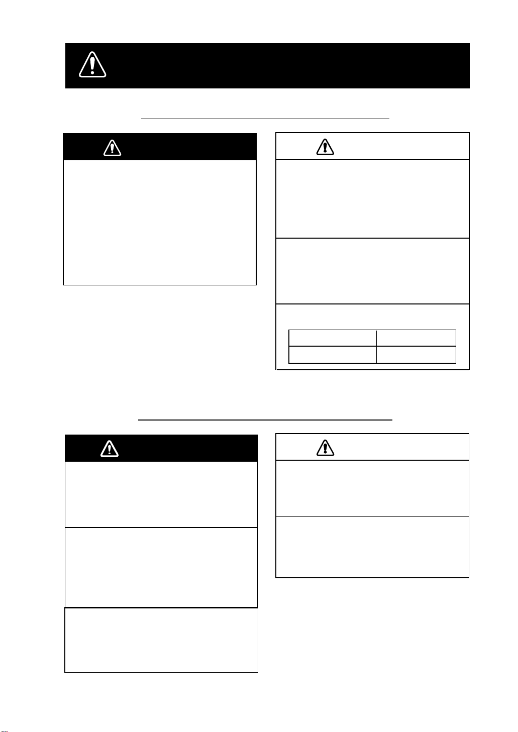
Safety Information for the Installer
WARNING
Turn off the power at the mains
switchboard before beginning the
installation.
Post a sign near the switch to indicate
it should not be turned on while the
equipment is being installed.
Fire or electrical shock can result if the
power is left on or is applied while the
equipment is being installed.
Safety Information for the Operator
CAUTION
Confirm that the power supply voltage
is compatible with the voltage rating
of the equipment.
Connection to the wrong power supply
can cause fire or equipment damage.
Use the supplied power cable.
Use of a wrong power cable can cause
fire or equipment damage.
Maintain the compass safe distance.
Standard compass
0.5 m
Steering compass
0.4 m
WARNING
Do not disassemble or modify the
equipment.
Fire, electrical shock or serious injury can
result.
Turn off the power immediately if water
leaks into the equipment or the
equipment is emitting smoke or fire.
Continued use of the equipment can cause
fire or electrical shock.
Do not place liquid-filled containers on
the top of the equipment.
Fire or electrical shock can result if a liquid
spills into the equipment.
CAUTION
Turns off the autopilot before selecting
output data format.
The autopilot may turn the rudder suddenly.
Turns off the autopilot before aligning
heading.
The autopilot may turn the rudder suddenly.
iiiiiiiiiiiii
i
Page 4

FOREWORD
A Word to PG-1000 Owners
Congratulations on your choice of the FURUNO PG-1000 Integrated Heading Sensor. We are
confident you will see why the FURUNO name has become synonymous with quality and
reliability.
For over 50 years Furuno Electric Company has enjoyed an enviable reputation for innovative
and dependable marine electronics equipment. This dedication to excellence is furthered by our
extensive global network of sales and service.
Your heading sensor is designed and constructed to meet the rigorous demands of the marine
environment. However , no machine can perform its intended function unless operated and maintained properly. Please carefully read and follow the recommended procedures for installation,
operation and maintenance.
We would appreciate hearing from you about whether we are achieving our purposes.
Thank you for choosing FURUNO equipment.
Features
• The PG-1000 uses a flaxgate magnetic sensor in conjunctions with solid-state angular rate
sensor to find heading.
• Automatic correction of magnetic variation
• Can convert magnetic heading to true heading (requires Furuno GPS Navigator).
ii
Page 5

TABLE OF CONTENTS
SYSTEM CONFIGURATION.............................................................. iv
SPECIFICATIONS..........................................................................SP-1
1 INSTALLATION
1.1 Equipment List ....................................................................................................................1
1.2 Selecting Mounting Location ..............................................................................................2
1.3 Mounting .............................................................................................................................3
1.4 Connections .........................................................................................................................4
1.5 Correcting Magnetic Field Distortion (Deviation) ..............................................................5
1.6 Heading Alignment..............................................................................................................6
1.7 Setting Output Data .............................................................................................................6
2 CORRECTING MAGNETIC ANOMALIES
2.1 Controls and Indications...................................................................................................... 8
2.2 Turning the Power On/Off ...................................................................................................8
2.3 Automatic Distortion Compensation ................................................................................... 9
2.4 Selecting Output Data Format .............................................................................................9
3 MAINTENANCE & TROUBLESHOTTING
3.1 Maintenance.......................................................................................................................10
3.2 Troubleshooting................................................................................................................. 10
3.3 Diagnostic Test .................................................................................................................. 11
3.4 Displaying Program Version No........................................................................................12
PARTS LOCATION AND LIST...................................................... AP-1
OUTLINE DRAWING .......................................................................D-1
SCHMATIC DIAGRAM..................................................................... S-1
iii
Page 6
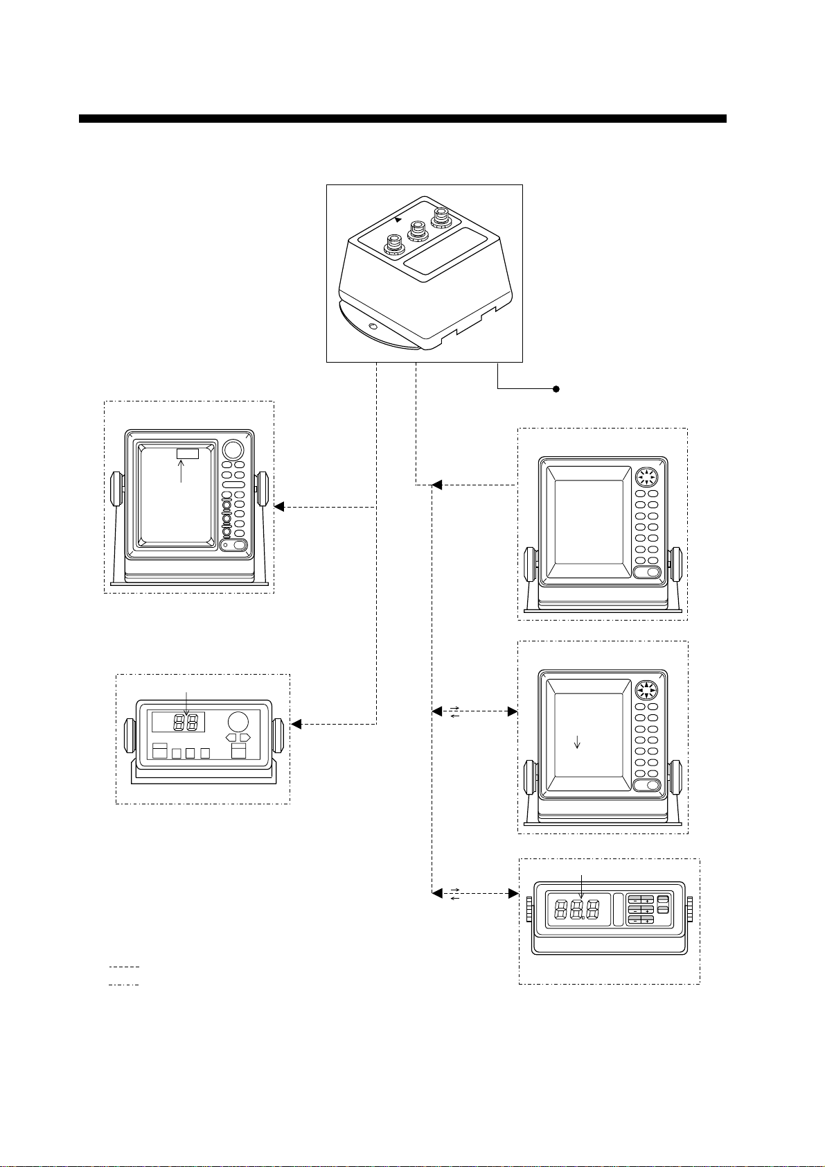
SYSTEM CONFIGURATION
PG-1000
RADAR/ARPA (ex: MODEL1832)
AD-10
NMEA
10.0 - 35.0 VDC
HDG 88.8°
Heading
Heading
AUTOPILOT (ex: FAP-300)
Magnetic or true
heading
Magnetic or true
heading
Magnetic
variation data
Magnetic or true
heading
Magnetic
variation data
GPS NAVIGATOR (ex: GP-1610C)
CURRENT INDICATOR (ex: CI-1000)
Course
CSE 88.8°
iv
Optional equipment
Local Supply
Magnetic or true
heading
Deviation at the
PG-1000 can be
corrected from the
Remote Display
DD-2000.
Heading
ON
OFF
DISPLAY UNIT (ex: DD-2000)
Page 7

SPECIFICATIONS OF INTEGRATED HEADING SENSOR
PG-1000
The PG-1000 is an electromagnetic compass consisting of a fluxgate and a solid-state rate
gyro, supported with advanced software. The heading information is outputted in IEC 61162-1
or NMEA format. For high data speed, AD-10 format (25 ms) is also available. The heading
information is used for radar, AIS, ECDIS, automatic steering system and other navaids.
Heading Accuracy Static ±1.0° (within 30° of tilt) after correcting deviation
Freedom of tilt ±35°
Follow-up 25°/s rate-of turn
Display resolution 0.1°
Useable area 70°N to 70°S
Correction of anomaly Deviation: Automatic correction of coefficients A, B, C, D, E by
turning the ship (manual by optional DD-2000 display unit)
I/O Port Input: 1 port
Output: 2 ports
Interfacing Output
FURUNO AD-10 format, IEC 61162-1 (NMEA 0183 Ver.2.0)
$HCHDG,XXX.X,,,,<CR><LF>
$HCHDT,XXX.X,T<CR><LF>
For old equipment:
$HCHDM,XXX.X,M<CR><LF>
$HCHCC,XXX.X,<CR><LF>
Input
IEC 61162-1 (NMEA 0183 Ver.2.0)
$--RMC or $--VTG,
either is required for correction of variation
Data Update AD-10 formatted: 25 ms
IEC 61162-1 (NMEA 0183): 1 s, 2 s, 100 ms or 200 ms selected
Power supply 12-24 VDC: 0.2-0.08 A
ENVIRONMENTAL CONDITION
Temperature -15°C to +55°C (15°C to 35°C for accuracy ±1.5°)
Waterproofing IP5 (IEC 60529), CFR-46 (USCG standard)
EMC and others Complies with IEC 60945
Coating Housing: Munsell scale N3.0 (Dark gray)
Dimensions and mass refer to the Outline Drawings
SP - 1
Page 8

1 INSTALLATION
1.1 Equipment List
Standard set
.oN emaNepyT.oNedoCytQskrameR
1rosneSE-0001-GP----1
2slairetaMnoitallatsnI00020-46PC334-040-0001 .wolebelbatotrefeR
Installation materials (CP64-02000)
.oN emaNepyT.oNedoCytQskrameR
1wercsgnippaT403SUS61x4080-208-0002
2rehsawtalF403SUS4M621-468-0002
3elbacrewoP9100S22000-901-0001
4.yssaelbaC001-7000FPS6A-JM732-521-0001
Optional units
.oN emaNepyT.oNedoCytQskrameR
1elbaclangiS050-3000FPS6A-JM306-711-0001 )01-DArof(m5,rotcennoc/w
2.yssaelbaC
001-7000FPS6A-JM732-521-0001 )01-DArof(m01,p6-p6
001-2100FPS6A-JM718-331-0001 )AEMNrof(m01,p6-p6
1
Page 9

1.2 Selecting Mounting Location
The PG-1000 must be indoor on the horizontal plane.
When selecting a mounting location, keep in
mind the following points:
• The ambient temperature must be between
-15°C and 55°C.
• Vibration at the mounting location should
be minimal.
• Install the sensor as far as possible from
power cable, ferrous materials.
• Install the sensor ship's center of gravity.
• Align the bow mark with the ship's bow on
the fore-and-aft-line.
1. T entatively select the mounting location. Do
not fix it yet.
Ship's bow
Bow mark
BOW
12-24 VDC
Red
+
12-24 VDC
+
Sensor (top view)
Black
-
NMEA
-
Å~
AD10
Grounding
Figure 2 Battery connections to PG-1000
3. Turn the ship's mains switch on.
This sensor doesn't have power switch.
Figure 1 PG-1000
2. Connect the PG-1000 to the battery as
shown in right.
AUTO TRUE
: On
: Blinking
: Off
: Status depends on settings.
CALIB
About two minutes later
STATUS
Figure 3 LEDs at power on
4. Confirm that the STATUS LED blinks.
Two minutes later it will light. If STATUS
LED doesn't blink and then light, suspect
sensor error . Reset power.
AUTO
TRUE CALIB STATUS
normal
error
: On
: Status depends on settings
: Off
2
Figure 4
Page 10

5. Press the [AUTO] and [+] keys together
Ship's bow
Material: Brass
Bow mark
fixing hole
141
152
5.5
65
130
o All dimensions in mm.
o For added support, use nuts, bolts and
washers.
o Secure sufficient clearance around the
sensor for maintenance and checking.
This line should be at right
angles to the fore and aft line.
more than two seconds.
AUTO TRUE CALIB STATUS
CALIBRATION
AUTO TRUE
1.3 Mounting
1. Fix the sensor by using screws and washers
(supplied). The size of the fixing hole is ø
4.5 mm.
After the TRUE, CALIB and STATUS
LEDs light and AUTO LED blinks, rotate
the equipment 360º slowly, keeping it
uplight. If three LEDs are lighting, the
mounting location is suitable.
If one or more LED is off, the mounting
location is not suitable. Try to change the
location, and do step 5 again.
6. Press the [AUTO] and [TRUE] keys together to return to the normal mode. The
ST ATUS LED blinks while the sensor is being calibrated and lights steady when the
calibration is completed. Do not operate the
sensor while the LED is blinking; calibration will be incomplete.
INTEGRATED HEADING SENSOR
Figure 5 Key and LEDs
AUTO
TRUE CALIB STATUS
Figure 6
PG-1000
: On
: Blinking
Figure 7 Mounting the PG-1000
Note: Do not overtighten the screws or bolts;
the sensor may crack.
3
Page 11

Checking for inclination
CAUTION
Make sure that the PG-1000 is mounted horizontally by the following checks.
1. Press the [TRUE] and [+] keys more than
two seconds.
When the inclination is within ±5°, STATUS
LED lights and TRUE LED blinks.
AUTO TRUE CALIB STATUS
: On
: Blinking
: Off
Figure 8 LED status when
inclination is within ±5
°
If STATUS LED is off, the inclination is
over ±5°. In this case, relocate the sensor
to where inclination becomes within ±5°
or use a levelling brock.
2. Press the [AUTO] and [TRUE] keys more
than two seconds to return to the normal
mode. The STATUS LED blinks while the
sensor is being calibrated and lights when
the calibration is completed (return to normal mode). Do not operate the equipment
while the LED is blinking; calibration will
be incomplete.
BOW
12-24 VDC
12-24 VDC
+
Ground
terminal
NMEA
-
Heading data
AD10
Grounding
External equipment
(Radar, ARPA,
Autopilot, etc.)
Figure 9 Connections of sensor, top view
Grounding
Ground the PG-1000 as follows to prevent interference:
• The ground wire should be as short as pos-
sible.
• The ground wire should be about 1.25 sq
and not contain steel.
• Use only a closed end lug.
CAUTION
Ground the equipment
to prevent loss of sensitivity.
1.4 Connections
Connect cables as shown in the Figure 8.
Leave sufficient slack in cables for mainte-
nance and checking ease. If cables run outside
the bridge run them through conduit to protect
them from corrosion.
4
Connection of external equipment
IEC-61162-1: Digital interface IEC-61162-1
format input/output terminal. Output: HDG,
HDT, Input: RMC or VTG.
NMEA0183 (Ver.1.5): Outputs HDM (Mag-
netic Heading), HCC (Compass Heading).
AD-10: Outputs heading information in AD10 format.
Note: Cover unused connector(s) with the
rubber cap (supplied) to prevent ingress of
water.
Page 12

1.5 Correcting Magnetic Field
Distortion (Deviation)
The magnetic field at the sensor around ship is
subjects to change with the ship structure,
engins, electronic equipment or any ferrous
materials in the vicinity.
The correction result is shown with the
LEDs. When correction is successful, all
LEDs light. Wait 30 seconds for the sensor
to return to normal operation, or press the
[TRUE] key for quick return.
AUTO TRUE CALIB STATUS
The PG-1000 contains an automatic correction
facility against magnetic field distortion aboard
the ship.
1. Do this procedure in a calm water.
2. Steer the boat clockwise or counterclock-
wise in a circular course. Take more than
two minutes to complete the circle (at about
3 kt). While turning the boat, go to step 3.
2 minutes for a circle
(at about3 kt)
Figure 10
Note 1: Take at least 2 minutes to navigate
the circle, otherwise large error may result.
Note 2: For hover craft or simular vessel,
turn the vessel in a circle maintaining fixed
position.
3. Press [AUTO] and [TRUE] keys together
more than two seconds. The CALIB LED
blinks.
AUTO TRUE CALIB STATUS
: Blinking
: Off
Figure 11 Compensatin falt LED status
during compensation
Note: You can return to normal operation
at any time by pressing the [TRUE] key.
4. Continue turning the boat in a circle (three
to five times) until a result appears.
: On
Figure 12 LED status at successful
correction
Note 1: Do not turn off the power supply
during the correction. Data may be
corrupted.
Note 2: You may restart correction at
anytime during correction or while the
correction results are displayed, by pessing
[AUTO] key. After pressing the key the
AUTO LED lights for two seconds.
Note 3: Continue turning the boat even if
the CALIB LED status changes from
blinking to lighting. Keys are inoperative
when the CALIB LED is lighting.
Note 4: The sensor does not output heading
data during the correction (Program Ver. 3
and after).
5. Anchor the boat at the pier to check sensor
heading to a known point (for example,
lighthouse).
If there is a compass error, see "1.6 Heading Alignment".
If some LED does not light, change sensor
location and repeat step 2 through 4.
If automatic correction failed at step 4, the
correction result is shown in LEDs. This
continues until you press any key to clear
the display.(Turning off the power at
switch board will not clear the LED display.)
Note: Bearing output is done with the
status before the automatic correction.
Failure of automatic correction may be
caused by the factors mentioned in the
table below. Try the correction again
referring to the table.
5
Page 13

Causes
CAUTION
Above range of
magnetic sensor
Magnetic field
distortion
Turning error
Results of correction
AUTO TRUE CALIB STATUS
Remedy
Follow the
procedure in
above from step
2 after the
replacement of
unit.
Follow the
procedure in
above from step
2 after the
replacement of
unit.
Follow the
procedure in
above from step
2.
: On
: Blinking
Figure 13
Note: Correction can also be done at Remote
Display DD-2000. See the Operator's Manual
for the DC-2000.
2. Set difference between sensor heading (output) and actual heading with the [+] or [-]
key. For example, the hading output by the
sensor is 70° and the actual heading is 75°.
Therefore, the difference is +5°. Press the
[+] key five times to set +5°. Each time the
[+] key is pressed the LEDs light as shown
in Figure 14.
+1°
+2°
+3°
+4°
+5°
+6°
+7°
AUTO
TRUE CALIB
STATUS
1.6 Heading Alignment
Heading alignment is required when sensor
heading is different from actual heading.
This alignment must be done using magnetic
heading (default setting).
CAUTION
Turn off the autopilot before aligning
heading.
The autopilot may turn the rudder suddenly.
Procedure
1. Press the [-] and [+] keys together more than
two seconds. All LEDs go off.
Repeat
: On
: Off
Figure 15 LED state and pressing of [+] key
1.7 Setting Output Data
Setting output interval
The deffault setting is 100 ms.
1. Disconnect the power connector from the
sensor.
2. Reattach the connector to the sensor while
pressing the [+] key. The PG-1000 is powered on, and the current output interval is
shown by the LEDs.
AUTO TRUE CALIB
STATUS
AUTO
TRUE CALIB STATUS
: Off
Figure 14
Note: Complete the next step within 10 seconds, otherwise normal operation is restored.
6
100ms
200ms
1s
2s
: On
: Off
Figure 16 LED state and output interval
Page 14

3. Press the [+] or [-] key to change interval.
4. Press the [AUTO] and [TRUE] keys together more than two seconds to return to
the normal mode. The ST ATUS LED blinks
while the equipment is being calibrated and
lights when the calibration is completed (return to normal mode). Do not operate the
equipment while the LED is blinking; calibration will be incomplete.
Setting the output sentence(s)
Select which type(s) of heading data to
output. The default setting is HDG.
1. Disconnect the power connector from the
sensor.
2. Reattach the connector to the sensor while
pressing the [-] key. The PG-1000 is powered on, and LED(s) light to show which
output sentence(s) is being output.
4. Press the [AUTO] and [TRUE] keys together more than two seconds to return to
the normal mode. The ST ATUS LED blinks
while the equipment is being calibrated and
lights when the calibration is completed (return to normal mode). Do not operate the
equipment while the LED is blinking; calibration will be incomplete.
AUTO TRUE CALIB STATUS
sentence
HDG HDT HDM
HDG
: Magnetic heading,
Magnetic variation value
HDT
: True heading
HDM
: Magnetic heading
HCC
: Compass heading
HCC
:On (current selection)
:Off
Figure 17 LED and output sentence
3. Press key(s) corresponding to sentence(s)
to output. For example, press the [TRUE]
key to output HDT.
Note 1: Several sentences may be output
simultaneously. However, delay may
result when the output interval is 100 ms
or 200 ms.
Note 2: "HDT" outputs true heading data.
However, if variation data is not input
from the GPS navigator, magnetic bearing
will be output.
7
Page 15

2 CORRECTING MAGNETIC
ANOMALIES
2.1 Controls and Indications
On: Auto correction is on.
Off: Auto correction is off.
On: True heading is output.
Off: Magnetic heading is output.
Off: Normal
Blinking: Correcting
the deviation.
(On installing.)
On: Normal
Off: Error
AUTO TRUE CALIB STATUS
CALIBRATION
AUTO TRUE
INTEGRATED HEADING SENSOR
Corrects the heading.
Selects output data format; magnetic or true
PG-1000
2.2 Turning the Power On/Off
Note: You may leave port after the STATUS
LED begins lighting (not blinking).
Power to the sensor unit may be turned on or
off at the mains switchboard.
1. Turn the mains switch on.
STATUS LED blinks. About two minutes
later it lights. Bearing is now reliable.
AUTO TRUE
AUTO
TRUE CALIB STATUS
: On
: Blinking
: Status depends on settings
: Off
CALIB
About two minutes later
STATUS
normal
error
Turns on and off deviation corrections.
Figure 18 Front panel of PG-1000
8
Figure 19 LED state at power on
Page 16

2.3 Automatic Distortion
CAUTION
Compensation
Magnetic field distortion can be automatically
corrected as follows:
Note: This function is only ef fective after correcting for magnetic field distortion (refer to
page 5).
RMC or VTG data is required which
contains GPS position in RMC, SOG
(speed over ground) and COG (course
over ground) in VTG.
2. Set up magnetic variation (manual or automatic) at the GPS navigator.
3. Press the [TRUE] key more than two seconds.
1. Press the [AUTO] key more than two seconds to light the AUTO LED.
AUTO
TRUE CALIB STATUS
:On
:Off
:State depends on settings
Figure 20
2. T o cancel automatic compensation, press the
[AUTO] key more than two second to turn
off the AUTO LED.
Note 1: Turn of f this function when your boat
is near a steel ship or iron bridge, since they
affect sensor performance.
Note 2: Correct distortion whenever you feel
error is excessive.
2.4 Selecting Output Data
Format
The PG-1000 can output heading true or magnetic. The default setting is magnetic heading
in AD-10 format.
CAUTION
Turn off the autopilot before selecting
output data format.
The TRUE LED blinks. It lights when
receiving data from the navaid.
AUTO TRUE
When receiving magnetic
variation data from the navaid.
: On
: Blinking
: Off
: Status depends on settings.
CALIB
STATUS
Figure 21
Note: If the TRUE LED dose not light within
90 seconds after pressing the [TRUE] key,
check that the GPS navigator is connected and
properly working.
4. To return to magnetic heading output, press
the [TRUE] key more than two seconds to
turn off the TRUE LED.
Note 1: If the PG-1000 stops receiving magnetic variation data while outputting true heading, the TRUE LED stops lighting and blinks.
The last used variation data is used.
Note 2: Magnetic variation cannot be corrected
manually at the PG-1000. Therefore, if you
desire true heading output but do not have a
navigation aid, you may enter appropriate
variation as shown in 1.6 Heading Alignment
on page 6.
The autopilot may turn the rudder suddenly.
1. Connect Furuno GPS Navigator to PG-
1000.
Note 3: HDM and HCC sentence are magnetic
heading output sentences. HDG sentence must
be changed to true heading at the equipment
connected, by using the magnetic heading and
magnetic variation data in the sentence.
9
Page 17

3 MAINTENANCE &
TROUBLESHOOTING
3.1 Maintenance
Regular maintenance is important to maintain intended performance over a long period.
Regularly check the following:
• Clean the component with a soft cloth. Do not use chemical cleaners; they can remove paint
and markings.
• Make sure all connections are tight.
• Check the ground terminal for corrosion. Clean if necessary.
3.2 Troubleshooting
The table below provides simple troubleshooting procedures which the user can follow to restore normal operation. If normal operation cannot be restored do not check inside the equipment; there are no user-serviceable parts inside. Any repair work should be referred to a qualified
technician.
motpmySydemeR
.derewopebtonnactinU.rotcennocrewopkcehC•
.thgiltonodsDEL.rotcennocrewopkcehC•
.rorreatadgnidaeH.tset-flesehtoD•
ottuptuotonsiatadgnidaehehT
.tnempiuqelanretxe
.sniams'pihsehtkcehC•
.tsetcitsongaidehtoD•
).egaptxenehtotrefeR(
).egaptxenehtotrefeR(
.snoitcennockcehC•
.tsetcitsongaidehtoD•
).egaptxenehtotrefeR(
10
Page 18

3.3 Diagnostic test
The PG-1000 has a self-test which checks the
circuit board and keys for proper operation.
LED/KEY/ROM/RAM test
1. Disconnect the power cable from the equip-
ment.
2. While pressing the [AUTO] key, reattach
the power cable.
The test sequence is as below.
AUTO
TRUE CALIB
STATUS
LED lights one by
one from the left-side.
5. Press the [AUTO] and [TRUE] keys together more than two seconds to escape
from the test. The STATUS LED blinks
while the equipment is being calibrated and
lights when the calibration is completed (return to normal mode). Do not operate the
sensor while the LED is blinking; calibration will be incomplete.
EEPROM/Sensor test
This test checks the EEPROM and sensor . All
default settings (navigation setting, output sentence, output interval, etc.) are restored at the
completion of the test. Do this test after dismounting the equipment.
1. Disconnect the power cable off from the
equipment.
2. While pressing the [TRUE] key , reattach the
cable. All LEDs go off.
Blink twice.
All LEDs go off.
: On
: Blinking
: Off
Figure 22 Sequence of LED test
3. Press each key one by one.
LED corresponding to the key lights if the
key is normal.
[AUTO] key: AUTO LED
[TRUE] key: TRUE LED
[-] key: CALIB LED
[+] key: STATUS LED
4. Press the [AUTO] and [TRUE] keys to-
gether more than two seconds after checking all keys. Then, the ROM and RAM are
checked.
3. After AUT O LED lights, turn the equipment
through a circle slowly instead of ship's
movement until TRUE LED lights. The test
proceeds in the sequence shown below.
When the equipment finds error, LEDs do not
light.
Start
EEPROM:
OK
Mag.
sensor: OK
Angle
OK
sensor:
Rate
OK
sensor:
AUTO TRUE CALIB
: On (normal)
: Off (error)
STATUS
Figure 23 EEPROM/Sensortest sequence
AUTO LED lights: RAM is normal.
TRUE LED lights: ROM is normal.
11
Page 19

4. Disconnect the power cable off from the
equipment, and then reattach it.
5. Mount the equipment at the previous position, referring to page 3.
3.4 Displaying Program
Version No.
When the equipment is powered on, the program no., denoted by LEDs in binary notation,
is shown about 1 second.
For example, LED state shown below means
the program no. is 5.
AUTO TRUE CALIB STATUS
8421
: On
: Off
Figure 24 LED state and
program version no.
12
Page 20

PARTS LOCA TION AND LIST
CPU Boa
PG-1000, cover opened
rd
emaNepyT.oNedoCskrameR
draoBUPC5311P46011-514-400
AP-1
Page 21

Page 22

Page 23

 Loading...